EP1426533A2 - Device for fixing fittings to multiple chamber profiles - Google Patents
Device for fixing fittings to multiple chamber profiles Download PDFInfo
- Publication number
- EP1426533A2 EP1426533A2 EP03018882A EP03018882A EP1426533A2 EP 1426533 A2 EP1426533 A2 EP 1426533A2 EP 03018882 A EP03018882 A EP 03018882A EP 03018882 A EP03018882 A EP 03018882A EP 1426533 A2 EP1426533 A2 EP 1426533A2
- Authority
- EP
- European Patent Office
- Prior art keywords
- mounting screw
- thread
- screw
- external thread
- mounting
- Prior art date
- Legal status (The legal status is an assumption and is not a legal conclusion. Google has not performed a legal analysis and makes no representation as to the accuracy of the status listed.)
- Granted
Links
- 238000003780 insertion Methods 0.000 claims description 7
- 230000037431 insertion Effects 0.000 claims description 7
- 230000007423 decrease Effects 0.000 claims description 2
- 238000006073 displacement reaction Methods 0.000 description 4
- 238000010521 absorption reaction Methods 0.000 description 2
- 238000000418 atomic force spectrum Methods 0.000 description 2
- 238000009413 insulation Methods 0.000 description 2
- 238000004873 anchoring Methods 0.000 description 1
- 230000005540 biological transmission Effects 0.000 description 1
- 230000009365 direct transmission Effects 0.000 description 1
- 230000000694 effects Effects 0.000 description 1
- 238000004049 embossing Methods 0.000 description 1
- 230000002349 favourable effect Effects 0.000 description 1
- 239000000835 fiber Substances 0.000 description 1
- 239000000463 material Substances 0.000 description 1
- 238000000034 method Methods 0.000 description 1
- 238000010079 rubber tapping Methods 0.000 description 1
- 238000005482 strain hardening Methods 0.000 description 1
Images
Classifications
-
- E—FIXED CONSTRUCTIONS
- E05—LOCKS; KEYS; WINDOW OR DOOR FITTINGS; SAFES
- E05B—LOCKS; ACCESSORIES THEREFOR; HANDCUFFS
- E05B1/00—Knobs or handles for wings; Knobs, handles, or press buttons for locks or latches on wings
- E05B1/0015—Knobs or handles which do not operate the bolt or lock, e.g. non-movable; Mounting thereof
-
- E—FIXED CONSTRUCTIONS
- E05—LOCKS; KEYS; WINDOW OR DOOR FITTINGS; SAFES
- E05D—HINGES OR SUSPENSION DEVICES FOR DOORS, WINDOWS OR WINGS
- E05D5/00—Construction of single parts, e.g. the parts for attachment
- E05D5/02—Parts for attachment, e.g. flaps
- E05D5/0215—Parts for attachment, e.g. flaps for attachment to profile members or the like
- E05D5/0223—Parts for attachment, e.g. flaps for attachment to profile members or the like with parts, e.g. screws, extending through the profile wall or engaging profile grooves
- E05D5/023—Parts for attachment, e.g. flaps for attachment to profile members or the like with parts, e.g. screws, extending through the profile wall or engaging profile grooves with parts extending through the profile wall
-
- E—FIXED CONSTRUCTIONS
- E05—LOCKS; KEYS; WINDOW OR DOOR FITTINGS; SAFES
- E05D—HINGES OR SUSPENSION DEVICES FOR DOORS, WINDOWS OR WINGS
- E05D7/00—Hinges or pivots of special construction
- E05D7/04—Hinges adjustable relative to the wing or the frame
- E05D7/043—Hinges adjustable relative to the wing or the frame by means of dowel attachments
-
- E—FIXED CONSTRUCTIONS
- E05—LOCKS; KEYS; WINDOW OR DOOR FITTINGS; SAFES
- E05Y—INDEXING SCHEME RELATING TO HINGES OR OTHER SUSPENSION DEVICES FOR DOORS, WINDOWS OR WINGS AND DEVICES FOR MOVING WINGS INTO OPEN OR CLOSED POSITION, CHECKS FOR WINGS AND WING FITTINGS NOT OTHERWISE PROVIDED FOR, CONCERNED WITH THE FUNCTIONING OF THE WING
- E05Y2201/00—Constructional elements; Accessories therefore
- E05Y2201/60—Suspension or transmission members; Accessories therefore
- E05Y2201/622—Suspension or transmission members elements
- E05Y2201/628—Bearings
- E05Y2201/632—Sleeves
-
- E—FIXED CONSTRUCTIONS
- E05—LOCKS; KEYS; WINDOW OR DOOR FITTINGS; SAFES
- E05Y—INDEXING SCHEME RELATING TO HINGES OR OTHER SUSPENSION DEVICES FOR DOORS, WINDOWS OR WINGS AND DEVICES FOR MOVING WINGS INTO OPEN OR CLOSED POSITION, CHECKS FOR WINGS AND WING FITTINGS NOT OTHERWISE PROVIDED FOR, CONCERNED WITH THE FUNCTIONING OF THE WING
- E05Y2600/00—Mounting or coupling arrangements for elements provided for in this subclass
- E05Y2600/60—Mounting or coupling members; Accessories therefore
- E05Y2600/61—Threaded members
-
- F—MECHANICAL ENGINEERING; LIGHTING; HEATING; WEAPONS; BLASTING
- F16—ENGINEERING ELEMENTS AND UNITS; GENERAL MEASURES FOR PRODUCING AND MAINTAINING EFFECTIVE FUNCTIONING OF MACHINES OR INSTALLATIONS; THERMAL INSULATION IN GENERAL
- F16B—DEVICES FOR FASTENING OR SECURING CONSTRUCTIONAL ELEMENTS OR MACHINE PARTS TOGETHER, e.g. NAILS, BOLTS, CIRCLIPS, CLAMPS, CLIPS OR WEDGES; JOINTS OR JOINTING
- F16B35/00—Screw-bolts; Stay-bolts; Screw-threaded studs; Screws; Set screws
- F16B35/04—Screw-bolts; Stay-bolts; Screw-threaded studs; Screws; Set screws with specially-shaped head or shaft in order to fix the bolt on or in an object
-
- F—MECHANICAL ENGINEERING; LIGHTING; HEATING; WEAPONS; BLASTING
- F16—ENGINEERING ELEMENTS AND UNITS; GENERAL MEASURES FOR PRODUCING AND MAINTAINING EFFECTIVE FUNCTIONING OF MACHINES OR INSTALLATIONS; THERMAL INSULATION IN GENERAL
- F16B—DEVICES FOR FASTENING OR SECURING CONSTRUCTIONAL ELEMENTS OR MACHINE PARTS TOGETHER, e.g. NAILS, BOLTS, CIRCLIPS, CLAMPS, CLIPS OR WEDGES; JOINTS OR JOINTING
- F16B37/00—Nuts or like thread-engaging members
-
- F—MECHANICAL ENGINEERING; LIGHTING; HEATING; WEAPONS; BLASTING
- F16—ENGINEERING ELEMENTS AND UNITS; GENERAL MEASURES FOR PRODUCING AND MAINTAINING EFFECTIVE FUNCTIONING OF MACHINES OR INSTALLATIONS; THERMAL INSULATION IN GENERAL
- F16B—DEVICES FOR FASTENING OR SECURING CONSTRUCTIONAL ELEMENTS OR MACHINE PARTS TOGETHER, e.g. NAILS, BOLTS, CIRCLIPS, CLAMPS, CLIPS OR WEDGES; JOINTS OR JOINTING
- F16B5/00—Joining sheets or plates, e.g. panels, to one another or to strips or bars parallel to them
- F16B5/02—Joining sheets or plates, e.g. panels, to one another or to strips or bars parallel to them by means of fastening members using screw-thread
Definitions
- the invention relates to a device for fastening of fittings Multi-chamber profiles with the features of the preamble of claim 1.
- Such devices are known for example from DE 100 00 226.
- the known device which serves for example the attachment of door handles, has a sleeve-shaped mounting screw, which in a borehole by means of a External thread in a multi-chamber profile, such as a door or the like., is attached.
- a positioning element At the insertion end of the mounting screw is a positioning element with a Internal thread provided.
- the positioning element is relative to the mounting screw in radial direction with respect to the longitudinal axis of the mounting screw movable.
- One Threaded bolt is screwed into the internal thread of the positioning and verkontert against the opposite end of the mounting screw. He serves the actual attachment of the fitting.
- the invention proposes a door handle on the threaded bolt by means of a locking pin by a To fix cross bore of the retaining bolt as a holding means. Furthermore, the beats Invention that the external thread of the mounting screw as a self-tapping Thread is performed so that only a hole without a thread are pre-drilled got to. The mounting screw can thus with the insertion into the hole can be used and can then be screwed.
- the Mounting bolt mounting engagement surfaces on, for example, a hexagon socket, and a stop collar that limits the depth of engagement and the mounting screw verkontert against the multi-chamber profile.
- the known device has the disadvantage on that transverse forces on the fitting part on the one hand via frictional forces on the counter surfaces between threaded bolt and mounting screw and on the other hand on the Introduced arranged internal thread of the positioning in the Mounting screw and are introduced from there into the multi-chamber profile. By This unfavorable force curve can easily cause displacements of the fitting come opposite the multi-chamber profile.
- the invention is therefore based on the object, a fastening device create, the high transverse force absorption, a reliable protection against displacement as well as a simple assembly guaranteed.
- the ganbund has an outer circumference centering in a bore of the Fitting part engages. This intervention creates a direct link between Fitting part and mounting screw reached. Transverse forces on the fitting become so directly and positively introduced into the multi-chamber profile.
- the ganbund on its outer periphery a toothing on. This toothing attacks again centering in a bore of the fitting part.
- the Head circle diameter of the teeth on the plant covenant larger and the Root diameter of the toothing smaller than the diameter of the bore of the tooth Fitting part executed.
- the teeth dig into the wall of the Drill hole in fitting part.
- a form-fitting Transmission of torsional moments achieved. Both a shift in radial Direction as well as a twisting of the fitting relative to the mounting screw is therefore excluded even at high shear forces.
- a preferred embodiment of the mounting screw has an external thread whose Core diameter decreases in the direction of insertion, for example, conical.
- The remains Flank height constant.
- the thread so not cut into the walls of the multi-chamber profile, but reshaping imprinted. This causes strain hardening during forming without Fiber interruption and thus significantly higher holding values.
- the external thread is designed as a multi-thread fine thread.
- the execution of a fine thread causes an increase in Holding values compared to a standard thread. Through the multi-course is ensures that it does not become a radial at the beginning of embossing the flanks Displacement of the mounting bolt against the borehole due to Passive forces is coming.
- the external thread of the mounting screw is up trained to stop collar. This ensures that even the Outside wall of the multi-chamber profile bearing effect. This increases opposite to a thread outlet both the holding forces and the ability to Absorption of shear forces without radial displacement.
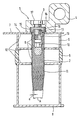
- Figure 1 shows a sectional view of a device according to the invention in the installed state.
- the device 1 consists of a mounting screw 2 and a fastening screw 3. It serves to attach the fitting part 4 to the multi-chamber profile 5.
- the multi-chamber profile 5 has a thermal insulation 6 made of plastic, whereby a heat flow, for example, from the front 7 to the back 8 is reduced ,
- the mounting screw 2 is screwed into this hole 9.
- the mounting screw 2 as a hexagon socket pronounced mounting attack surfaces 10.
- the external thread 11 of the mounting screw 2 is impressed when screwed into the walls 12 of the multi-chamber profile 5 a.
- the external thread 11 has a tapering in the insertion direction conically with the cone angle a core diameter.
- the flank height a is constant over the entire length of the external thread 11. This ensures that the external thread 11 does not cut into the walls 12 of the multi-chamber profile 5 cuts, but it comes only to a forming process. As a result, the material is solidified, which has a favorable effect on the holding values of the device 1.
- the external thread 11 is pronounced up to the abutment collar 13, so that it also stops in the outer wall 14.
- the ganbund 13 After screwing the mounting screw 2, the fitting part 4 with his Drilled hole 15 over the ganbund 13.
- the ganbund 13 has a toothing 16, whose tip diameter is larger and whose root diameter is smaller as the diameter of the bore 15 is. This is the case when slipping over a digging of the teeth 16 in the bore 15. This ensures on the one hand a Centering of the fitting part 4 and on the other hand a positive, direct Transmission of lateral forces and torsional moments of the fitting part 4 on the Mounting screw 2.
- Axial tensile forces are mounted by the final Fixing screw 3 via the screw head 17 as a holding means and the Bolt thread 18 in the internal thread 19 of the mounting screw 2 transmitted.
- a Such arrangement ensures optimal introduction of all forces and Moments in the multi-chamber profile 5.
Abstract
Description
Die Erfindung betrifft eine Vorrichtung zur Befestigung von Beschlagteilen an
Mehrkammerprofilen mit den Merkmalen des Oberbegriffs des Anspruchs 1.The invention relates to a device for fastening of fittings
Multi-chamber profiles with the features of the preamble of
Derartige Vorrichtungen sind beispielsweise aus der DE 100 00 226 bekannt. Die bekannte Vorrichtung, die beispielsweise der Befestigung von Türgriffen dient, weist eine hülsenförmige Montageschraube auf, die in einem Bohrloch mittels eines Außengewindes in einem Mehrkammerprofil, beispielsweise einer Tür oder dgl., befestigt ist. Am Einführende der Montageschraube ist ein Positionierelement mit einem Innengewinde vorgesehen. Das Positionierelement ist relativ zur Montageschraube in radialer Richtung bezüglich der Längsachse der Montageschraube beweglich. Ein Gewindebolzen wird in das Innengewinde des Positionierelements geschraubt und gegen das entgegengesetzte Ende der Montageschraube verkontert. Er dient der eigentlichen Befestigung des Beschlagteils. So schlägt die Erfindung beispielsweise vor, einen Türgriff an dem Gewindebolzen mittels eines Sicherungsstiftes durch eine Querbohrung des Haltebolzens als Haltemittel zu befestigen. Des Weiteren schlägt die Erfindung vor, dass das Außengewinde der Montageschraube als selbstschneidendes Gewinde ausgeführt wird, so dass lediglich ein Loch ohne Gewinde vorgebohrt werden muss. Die Montageschraube kann somit mit dem Einführende in das Bohrloch eingesetzt werden und kann dann eingeschraubt werden. Dazu weist die Montageschraube Montageangriffsflächen auf, beispielsweise einen Innensechskant, sowie einen Anschlagbund, der die Einschraubtiefe begrenzt und die Montageschraube gegen das Mehrkammerprofil verkontert.Such devices are known for example from DE 100 00 226. The known device, which serves for example the attachment of door handles, has a sleeve-shaped mounting screw, which in a borehole by means of a External thread in a multi-chamber profile, such as a door or the like., is attached. At the insertion end of the mounting screw is a positioning element with a Internal thread provided. The positioning element is relative to the mounting screw in radial direction with respect to the longitudinal axis of the mounting screw movable. One Threaded bolt is screwed into the internal thread of the positioning and verkontert against the opposite end of the mounting screw. He serves the actual attachment of the fitting. For example, the invention proposes a door handle on the threaded bolt by means of a locking pin by a To fix cross bore of the retaining bolt as a holding means. Furthermore, the beats Invention that the external thread of the mounting screw as a self-tapping Thread is performed so that only a hole without a thread are pre-drilled got to. The mounting screw can thus with the insertion into the hole can be used and can then be screwed. For this purpose, the Mounting bolt mounting engagement surfaces on, for example, a hexagon socket, and a stop collar that limits the depth of engagement and the mounting screw verkontert against the multi-chamber profile.
Im Gegensatz zu Vorrichtungen, bei denen die Befestigung durch ein Verspreizen der Montageschraube realisiert wird, treten bei der Montage kaum axiale Kräfte auf. Dies ist von Vorteil, wenn zwischen den der Verankerung dienenden Wänden des Mehrkammerprofils eine thermische Isolierung angeordnet ist, die sich im Falle von Axialkräften deformieren würde. Allerdings weist die bekannte Vorrichtung den Nachteil auf, dass Querkräfte am Beschlagteil einerseits über Reibkräfte an den Konterflächen zwischen Gewindebolzen und Montageschraube und andererseits über das am Einführende angeordnete Innengewinde des Positionierelements in die Montageschraube und von dort in das Mehrkammerprofil eingeleitet werden. Durch diesen ungünstigen Kraftverlauf kann es leicht zu Verschiebungen des Beschlagteils gegenüber dem Mehrkammerprofil kommen.In contrast to devices in which the attachment by splaying the Mounting screw is realized, hardly occur during assembly axial forces. This is advantageous if between the anchoring walls of the Multi-chamber profiles a thermal insulation is arranged, which in the case of Would deform axial forces. However, the known device has the disadvantage on that transverse forces on the fitting part on the one hand via frictional forces on the counter surfaces between threaded bolt and mounting screw and on the other hand on the Introduced arranged internal thread of the positioning in the Mounting screw and are introduced from there into the multi-chamber profile. By This unfavorable force curve can easily cause displacements of the fitting come opposite the multi-chamber profile.
Der Erfindung liegt daher die Aufgabe zugrunde, eine Befestigungsvorrichtung zu schaffen, die hohe Querkraftaufnahme, eine zuverlässige Sicherung gegen Verschieben sowie eine einfache Montage gewährleistet.The invention is therefore based on the object, a fastening device create, the high transverse force absorption, a reliable protection against displacement as well as a simple assembly guaranteed.
Diese Aufgabe wird erfindungsgemäß durch die Merkmale des Anspruchs 1 gelöst. Der
Anlagebund weist einen äußeren Umfang auf, der zentrierend in eine Bohrung des
Beschlagteils eingreift. Durch dieses Eingreifen wird eine direkte Verbindung von
Beschlagteil und Montageschraube erreicht. Querkräfte am Beschlagteil werden damit
direkt und formschlüssig in das Mehrkammerprofil eingeleitet. Vorzugsweise weist der
Anlagebund an seinem äußere Umfang eine Zahnung auf. Diese Zahnung greift
wiederum zentrierend in eine Bohrung des Beschlagteils ein. Vorzugsweise sind der
Kopfkreisdurchmesser der Zahnung am Anlagebund größer und der
Fußkreisdurchmesser der Zahnung kleiner als der Durchmesser der Bohrung des
Beschlagteils ausgeführt. Bei der Montage graben sich die Zahne in die Wandung der
Bohrung im Beschlagteil ein. Hierdurch wird neben der Zentrierung eine formschlüssige
Übertragung von Torsionsmomenten erreicht. Sowohl eine Verschiebung in radialer
Richtung als auch ein Verdrehen des Beschlagteils gegenüber der Montageschraube
wird damit auch bei hohen Querkräften ausgeschlossen.This object is achieved by the features of
Im Sinne dieses verbesserten Kraftverlaufs sieht eine bevorzugte Ausführung der Erfindung vor, dass das Innengewinde der Montageschraube zur Aufnahme von Kräften an der Befestigungsschraube im hinteren Ende der Montageschraube in Bezug auf dessen Einbringrichtung angeordnet ist.In the sense of this improved force curve, a preferred embodiment of the Invention before that the internal thread of the mounting screw for receiving forces with respect to the fixing screw in the rear end of the mounting screw whose introduction direction is arranged.
Eine bevorzugte Ausführung der Montageschraube weist ein Außengewinde auf, dessen Kerndurchmesser in Einbringrichtung beispielsweise konisch abnimmt. Dabei bleibt die Flankenhöhe konstant. Im Gegensatz zu der bekannten Vorrichtung wird das Gewinde damit nicht in die Wände des Mehrkammerprofils eingeschnitten, sondern umformend eingeprägt. Dies bewirkt eine Kaltverfestigung beim Umformen ohne Faserunterbrechung und damit deutlich höhere Haltewerte.A preferred embodiment of the mounting screw has an external thread whose Core diameter decreases in the direction of insertion, for example, conical. The remains Flank height constant. In contrast to the known device, the thread so not cut into the walls of the multi-chamber profile, but reshaping imprinted. This causes strain hardening during forming without Fiber interruption and thus significantly higher holding values.
Vorzugsweise ist das Außengewinde als mehrgängiges Feingewinde ausgebildet. Wie Versuche gezeigt haben, bewirkt die Ausführung als Feingewinde eine Steigerung der Haltewerte gegenüber einem Normalgewinde. Durch die Mehrgängigkeit wird gewährleistet, dass es bei beginnender Einprägung der Flanken nicht zu einer radialen Verschiebung der Montageschraube gegenüber dem Bohrloch aufgrund der Passivkräfte kommt.Preferably, the external thread is designed as a multi-thread fine thread. As Experiments have shown, the execution of a fine thread causes an increase in Holding values compared to a standard thread. Through the multi-course is ensures that it does not become a radial at the beginning of embossing the flanks Displacement of the mounting bolt against the borehole due to Passive forces is coming.
In einer bevorzugten Ausführungsform ist das Außengewinde der Montageschraube bis zum Anschlagbund ausgebildet. Hierdurch wird gewährleistet, dass auch der Außenwand des Mehrkammerprofils tragende Wirkung zukommt. Dies erhöht gegenüber einem Gewindeauslauf sowohl die Haltekräfte als auch die Fähigkeit zur Aufnahme von Querkräften ohne radiale Verschiebung.In a preferred embodiment, the external thread of the mounting screw is up trained to stop collar. This ensures that even the Outside wall of the multi-chamber profile bearing effect. This increases opposite to a thread outlet both the holding forces and the ability to Absorption of shear forces without radial displacement.
Die Erfindung wird nachfolgend anhand eines in der Zeichnung dargestellten Ausführungsbeispiels
näher erläutert. Figur 1 zeigt eine Schnittzeichnung einer
erfindungsgemäßen Vorrichtung im eingebauten Zustand. Die Vorrichtung 1 besteht aus
einer Montageschraube 2 und einer Befestigungsschraube 3. Sie dient der Befestigung
des Beschlagteils 4 an dem Mehrkammerprofil 5. Das Mehrkammerprofil 5 weist eine
thermische Isolierung 6 aus Kunststoff auf, wodurch ein Wärmefluss beispielsweise von
der Vorderseite 7 zur Rückseite 8 reduziert wird. Bei der Montage der Vorrichtung 1 wird
zunächst das Bohrloch 9 in das Mehrkammerprofil 5 eingebracht. Die Montageschraube
2 wird in dieses Bohrloch 9 eingeschraubt. Dazu weist die Montageschraube 2 als
Innensechskant ausgeprägte Montageangriffsflächen 10 auf. Das Außengewinde 11 der
Montageschraube 2 prägt sich beim Einschrauben in die Wände 12 des
Mehrkammerprofils 5 ein. Dazu weist das Außengewinde 11 einen in Einbringrichtung
sich konisch mit dem Konuswinkel a verjüngenden Kerndurchmesser auf. Die
Flankenhöhe a ist über die gesamte Länge des Außengewindes 11 konstant. Hierdurch
wird erreicht, dass sich das Außengewinde 11 nicht spanabhebend in die Wände 12 des
Mehrkammerprofils 5 schneidet, sondern es lediglich zu einem Umformvorgang kommt.
Hierdurch wird das Material verfestigt, was sich günstig auf die Haltewerte der
Vorrichtung 1 auswirkt. Das Außengewinde 11 ist bis zum Anlagebund 13 ausgeprägt,
so dass es auch in der Außenwand 14 Halt findet. Durch die Ausprägung des
Außengewindes als dreigängiges Feingewinde werden sowohl hohe Haltewerte als auch
eine gute Zentrierung im Bohrloch 9 erreicht.The invention will be explained in more detail with reference to an embodiment shown in the drawing. Figure 1 shows a sectional view of a device according to the invention in the installed state. The
Nach dem Einschrauben der Montageschraube 2 wird das Beschlagteil 4 mit seiner
Bohrung 15 über den Anlagebund 13 gestülpt. Der Anlagebund 13 weist eine Zahnung
16 auf, dessen Kopfkreisdurchmesser größer und dessen Fußkreisdurchmesser kleiner
als der Durchmesser der Bohrung 15 ist. Hierdurch kommt es beim Überstülpen zu
einem Eingraben der Zahnung 16 in die Bohrung 15. Dies gewährleistet einerseits eine
Zentrierung des Beschlagteils 4 und andererseits eine formschlüssige, direkte
Übertragung von Querkräften und Torsionsmomenten des Beschlagteils 4 auf die
Montageschraube 2. Axiale Zugkräfte werden durch die abschließend montierte
Befestigungsschraube 3 über dessen Schraubenkopf 17 als Haltemittel und das
Bolzengewinde 18 in das Innengewinde 19 der Montageschraube 2 übertragen. Eine
derartige Anordnung gewährleistet eine optimale Einleitung sämtlicher Kräfte und
Momente in das Mehrkammerprofil 5.After screwing the
Claims (8)
Applications Claiming Priority (2)
| Application Number | Priority Date | Filing Date | Title |
|---|---|---|---|
| DE20218699U DE20218699U1 (en) | 2002-12-03 | 2002-12-03 | Device for fastening fittings on multi-chamber profiles |
| DE20218699U | 2002-12-03 |
Publications (3)
| Publication Number | Publication Date |
|---|---|
| EP1426533A2 true EP1426533A2 (en) | 2004-06-09 |
| EP1426533A3 EP1426533A3 (en) | 2004-06-23 |
| EP1426533B1 EP1426533B1 (en) | 2014-11-12 |
Family
ID=32115647
Family Applications (1)
| Application Number | Title | Priority Date | Filing Date |
|---|---|---|---|
| EP20030018882 Expired - Lifetime EP1426533B1 (en) | 2002-12-03 | 2003-08-20 | Device for fixing fittings to multiple chamber profiles |
Country Status (6)
| Country | Link |
|---|---|
| EP (1) | EP1426533B1 (en) |
| CN (1) | CN100424317C (en) |
| DE (1) | DE20218699U1 (en) |
| PL (1) | PL218604B1 (en) |
| RU (1) | RU2291941C2 (en) |
| WO (1) | WO2004051038A1 (en) |
Cited By (2)
| Publication number | Priority date | Publication date | Assignee | Title |
|---|---|---|---|---|
| DE202005012152U1 (en) * | 2005-07-29 | 2006-12-07 | Dr. Hahn Gmbh & Co. Kg | Band arrangement for doors, windows or the like. |
| DE102010000214A1 (en) | 2010-01-27 | 2011-07-28 | fischerwerke GmbH & Co. KG, 72178 | Mounting arrangement for door, has layer arranged between fitting part and hollow-chamber section, where lateral forces are transferable between fitting part and hollow-chamber section by layer |
Families Citing this family (10)
| Publication number | Priority date | Publication date | Assignee | Title |
|---|---|---|---|---|
| DE202005001660U1 (en) | 2005-02-03 | 2006-06-14 | Dr. Hahn Gmbh & Co Kg | Mounting screw for fixing fittings |
| DE202005016547U1 (en) | 2005-10-20 | 2007-03-01 | Dr. Hahn Gmbh & Co. Kg | Mounting element for fastening fittings, in particular v. Band parts on a frame or on a wing |
| DE202005016552U1 (en) * | 2005-10-20 | 2007-03-01 | Dr. Hahn Gmbh & Co. Kg | Mounting arrangement of fitting parts, in particular band parts on a frame or on a wing |
| DE202005017976U1 (en) | 2005-11-15 | 2007-03-29 | Dr. Hahn Gmbh & Co. Kg | Mounting screw for fastening fitting parts, in particular of hinge parts to hollow chamber profiles |
| DE202006010207U1 (en) * | 2006-06-29 | 2007-11-08 | Dr. Hahn Gmbh & Co. Kg | Device for attachment to a profile |
| DE202006010208U1 (en) * | 2006-06-29 | 2007-11-08 | Dr. Hahn Gmbh & Co. Kg | Band assembly for attaching a wing to a frame |
| DE202007003675U1 (en) | 2007-03-09 | 2008-07-24 | Dr. Hahn Gmbh & Co. Kg | Device for fastening fittings to hollow sections |
| DE202012103721U1 (en) | 2012-09-28 | 2014-01-07 | Dr. Hahn Gmbh & Co. Kg | Mounting screw for fastening fittings, in particular band parts of hollow chamber profiles and a hollow chamber profile |
| CN104154091A (en) * | 2014-09-05 | 2014-11-19 | 无锡市翱宇特新科技发展有限公司 | Connection bolt |
| DE202016104904U1 (en) * | 2016-09-06 | 2017-12-07 | Dr. Hahn Gmbh & Co. Kg | System with a fitting and with a profile |
Citations (6)
| Publication number | Priority date | Publication date | Assignee | Title |
|---|---|---|---|---|
| DE3932193A1 (en) * | 1989-09-27 | 1991-04-04 | Bayerische Motoren Werke Ag | Vehicle roof-luggage-rack fixing device - has left-handed external and right-handed internal adjusting-bush threads |
| EP0864767A2 (en) * | 1997-03-11 | 1998-09-16 | Hewi Heinrich Wilke Gmbh | Junction sleeve and device for fastening articles to walls or the like |
| DE10000226A1 (en) * | 2000-01-05 | 2001-07-12 | Wilke Heinrich Hewi Gmbh | Assembly sleeve |
| DE10131340A1 (en) * | 2000-07-04 | 2002-01-17 | Witte Velbert Gmbh & Co Kg | Fixture incorporates fixture piece on second component, screw, spacer-piece, thrust element, and first and third components. |
| DE10033840A1 (en) * | 2000-07-12 | 2002-01-31 | Woelm & Sohn Karl | Door handle mounting uses selfcutting edge to threaded sleeve itself slotted out both ends and at flange collar using threaded pin to spread splay arms within panel. |
| WO2002038897A1 (en) * | 2000-11-07 | 2002-05-16 | Dr. Hahn Gmbh & Co. Kg | Bushing for fixing a fitting to a hollow profile which is provided with a projecting profiled part |
Family Cites Families (2)
| Publication number | Priority date | Publication date | Assignee | Title |
|---|---|---|---|---|
| DE29713594U1 (en) * | 1997-07-30 | 1997-11-13 | Salice Arturo Spa | Fastening plate for a fitting part, preferably for fastening a hinge arm to a supporting wall of a piece of furniture |
| CN2503165Y (en) * | 2001-09-30 | 2002-07-31 | 温州市坚士锁业有限公司 | Door lock handle assembly |
-
2002
- 2002-12-03 DE DE20218699U patent/DE20218699U1/en not_active Expired - Lifetime
-
2003
- 2003-08-20 EP EP20030018882 patent/EP1426533B1/en not_active Expired - Lifetime
- 2003-11-18 PL PL375592A patent/PL218604B1/en unknown
- 2003-11-18 WO PCT/EP2003/012871 patent/WO2004051038A1/en active Application Filing
- 2003-11-18 RU RU2005120744/12A patent/RU2291941C2/en not_active IP Right Cessation
- 2003-11-18 CN CNB2003801049570A patent/CN100424317C/en not_active Expired - Fee Related
Patent Citations (6)
| Publication number | Priority date | Publication date | Assignee | Title |
|---|---|---|---|---|
| DE3932193A1 (en) * | 1989-09-27 | 1991-04-04 | Bayerische Motoren Werke Ag | Vehicle roof-luggage-rack fixing device - has left-handed external and right-handed internal adjusting-bush threads |
| EP0864767A2 (en) * | 1997-03-11 | 1998-09-16 | Hewi Heinrich Wilke Gmbh | Junction sleeve and device for fastening articles to walls or the like |
| DE10000226A1 (en) * | 2000-01-05 | 2001-07-12 | Wilke Heinrich Hewi Gmbh | Assembly sleeve |
| DE10131340A1 (en) * | 2000-07-04 | 2002-01-17 | Witte Velbert Gmbh & Co Kg | Fixture incorporates fixture piece on second component, screw, spacer-piece, thrust element, and first and third components. |
| DE10033840A1 (en) * | 2000-07-12 | 2002-01-31 | Woelm & Sohn Karl | Door handle mounting uses selfcutting edge to threaded sleeve itself slotted out both ends and at flange collar using threaded pin to spread splay arms within panel. |
| WO2002038897A1 (en) * | 2000-11-07 | 2002-05-16 | Dr. Hahn Gmbh & Co. Kg | Bushing for fixing a fitting to a hollow profile which is provided with a projecting profiled part |
Cited By (2)
| Publication number | Priority date | Publication date | Assignee | Title |
|---|---|---|---|---|
| DE202005012152U1 (en) * | 2005-07-29 | 2006-12-07 | Dr. Hahn Gmbh & Co. Kg | Band arrangement for doors, windows or the like. |
| DE102010000214A1 (en) | 2010-01-27 | 2011-07-28 | fischerwerke GmbH & Co. KG, 72178 | Mounting arrangement for door, has layer arranged between fitting part and hollow-chamber section, where lateral forces are transferable between fitting part and hollow-chamber section by layer |
Also Published As
| Publication number | Publication date |
|---|---|
| CN100424317C (en) | 2008-10-08 |
| EP1426533A3 (en) | 2004-06-23 |
| CN1720381A (en) | 2006-01-11 |
| PL375592A1 (en) | 2005-12-12 |
| DE20218699U1 (en) | 2004-04-15 |
| RU2005120744A (en) | 2006-01-20 |
| RU2291941C2 (en) | 2007-01-20 |
| PL218604B1 (en) | 2015-01-30 |
| WO2004051038A1 (en) | 2004-06-17 |
| EP1426533B1 (en) | 2014-11-12 |
Similar Documents
| Publication | Publication Date | Title |
|---|---|---|
| DE102004034246B4 (en) | screw | |
| EP0955476B2 (en) | Fastening device with a self-tapping screw for insertion into construction elements made of concrete. | |
| DE19615191C2 (en) | Screw and method for the torque-limited fastening of metal and / or plastic profiles or plates on a substructure | |
| EP1426533B1 (en) | Device for fixing fittings to multiple chamber profiles | |
| EP1895173B1 (en) | Fastening assembly comprising an expandable dowel sleeve and an expanding screw | |
| EP0841491B1 (en) | Fastening element for a blind hole and method for setting fastening elements | |
| EP0905389A2 (en) | Screw for anchoring in concrete | |
| EP0988427B1 (en) | Connecting element for connecting at least two wooden construction parts and a joint plate | |
| DE19831338A1 (en) | Bone screw | |
| EP1598563B1 (en) | Connector system | |
| EP3587729B1 (en) | Connection of two drill string elements of a drill string for earth drilling | |
| DE19632468A1 (en) | Screw arrangement with screw fixture part | |
| DE102016101519A1 (en) | Screw, fastening arrangement, use of a fastening arrangement and method for producing a screw | |
| EP1948945B1 (en) | Mounting screw for fastening fitting parts, in particular hinge parts to hollow-chamber profiles | |
| EP3374649B1 (en) | Thread-forming screw | |
| CH654884A5 (en) | FASTENING KIT. | |
| EP1589236A1 (en) | A fixing system for connecting profiled bars | |
| DE102016000088A1 (en) | Screw | |
| DE202012103721U1 (en) | Mounting screw for fastening fittings, in particular band parts of hollow chamber profiles and a hollow chamber profile | |
| DE202007007550U1 (en) | Fastening system for assembling stands, stages, scaffolding or racking, shelving and frames has profiled rods with undercut longitudinal slots running parallel to each rod's axis | |
| EP2844884A1 (en) | Screw for lightweight construction materials | |
| WO2023062135A1 (en) | Frame screw | |
| DE4224572C2 (en) | Fastening element for use in concrete or the like material | |
| DE19960387A1 (en) | Plug-in dowel system | |
| DE202017105711U1 (en) | Fixing anchor for plastic frame |
Legal Events
| Date | Code | Title | Description |
|---|---|---|---|
| PUAI | Public reference made under article 153(3) epc to a published international application that has entered the european phase |
Free format text: ORIGINAL CODE: 0009012 |
|
| PUAL | Search report despatched |
Free format text: ORIGINAL CODE: 0009013 |
|
| AK | Designated contracting states |
Kind code of ref document: A2 Designated state(s): AT BE BG CH CY CZ DE DK EE ES FI FR GB GR HU IE IT LI LU MC NL PT RO SE SI SK TR |
|
| AX | Request for extension of the european patent |
Extension state: AL LT LV MK |
|
| AK | Designated contracting states |
Kind code of ref document: A3 Designated state(s): AT BE BG CH CY CZ DE DK EE ES FI FR GB GR HU IE IT LI LU MC NL PT RO SE SI SK TR |
|
| AX | Request for extension of the european patent |
Extension state: AL LT LV MK |
|
| 17P | Request for examination filed |
Effective date: 20041013 |
|
| AKX | Designation fees paid |
Designated state(s): AT BE BG CH CY CZ DE DK EE ES FI FR GB GR HU IE IT LI LU MC NL PT RO SE SI SK TR |
|
| RAP1 | Party data changed (applicant data changed or rights of an application transferred) |
Owner name: FISCHERWERKE GMBH & CO. KG Owner name: DR. HAHN GMBH & CO. KG |
|
| 17Q | First examination report despatched |
Effective date: 20101115 |
|
| GRAP | Despatch of communication of intention to grant a patent |
Free format text: ORIGINAL CODE: EPIDOSNIGR1 |
|
| INTG | Intention to grant announced |
Effective date: 20140414 |
|
| GRAS | Grant fee paid |
Free format text: ORIGINAL CODE: EPIDOSNIGR3 |
|
| GRAP | Despatch of communication of intention to grant a patent |
Free format text: ORIGINAL CODE: EPIDOSNIGR1 |
|
| GRAA | (expected) grant |
Free format text: ORIGINAL CODE: 0009210 |
|
| INTG | Intention to grant announced |
Effective date: 20141001 |
|
| RAP1 | Party data changed (applicant data changed or rights of an application transferred) |
Owner name: DR. HAHN GMBH & CO. KG Owner name: FISCHERWERKE GMBH & CO. KG |
|
| AK | Designated contracting states |
Kind code of ref document: B1 Designated state(s): AT BE BG CH CY CZ DE DK EE ES FI FR GB GR HU IE IT LI LU MC NL PT RO SE SI SK TR |
|
| REG | Reference to a national code |
Ref country code: GB Ref legal event code: FG4D Free format text: NOT ENGLISH |
|
| REG | Reference to a national code |
Ref country code: CH Ref legal event code: EP |
|
| REG | Reference to a national code |
Ref country code: AT Ref legal event code: REF Ref document number: 695892 Country of ref document: AT Kind code of ref document: T Effective date: 20141115 |
|
| REG | Reference to a national code |
Ref country code: IE Ref legal event code: FG4D Free format text: LANGUAGE OF EP DOCUMENT: GERMAN |
|
| REG | Reference to a national code |
Ref country code: DE Ref legal event code: R096 Ref document number: 50315154 Country of ref document: DE Effective date: 20141224 |
|
| REG | Reference to a national code |
Ref country code: SE Ref legal event code: TRGR |
|
| REG | Reference to a national code |
Ref country code: NL Ref legal event code: VDEP Effective date: 20141112 |
|
| PG25 | Lapsed in a contracting state [announced via postgrant information from national office to epo] |
Ref country code: PT Free format text: LAPSE BECAUSE OF FAILURE TO SUBMIT A TRANSLATION OF THE DESCRIPTION OR TO PAY THE FEE WITHIN THE PRESCRIBED TIME-LIMIT Effective date: 20150312 Ref country code: NL Free format text: LAPSE BECAUSE OF FAILURE TO SUBMIT A TRANSLATION OF THE DESCRIPTION OR TO PAY THE FEE WITHIN THE PRESCRIBED TIME-LIMIT Effective date: 20141112 Ref country code: ES Free format text: LAPSE BECAUSE OF FAILURE TO SUBMIT A TRANSLATION OF THE DESCRIPTION OR TO PAY THE FEE WITHIN THE PRESCRIBED TIME-LIMIT Effective date: 20141112 Ref country code: FI Free format text: LAPSE BECAUSE OF FAILURE TO SUBMIT A TRANSLATION OF THE DESCRIPTION OR TO PAY THE FEE WITHIN THE PRESCRIBED TIME-LIMIT Effective date: 20141112 |
|
| PG25 | Lapsed in a contracting state [announced via postgrant information from national office to epo] |
Ref country code: GR Free format text: LAPSE BECAUSE OF FAILURE TO SUBMIT A TRANSLATION OF THE DESCRIPTION OR TO PAY THE FEE WITHIN THE PRESCRIBED TIME-LIMIT Effective date: 20150213 Ref country code: CY Free format text: LAPSE BECAUSE OF FAILURE TO SUBMIT A TRANSLATION OF THE DESCRIPTION OR TO PAY THE FEE WITHIN THE PRESCRIBED TIME-LIMIT Effective date: 20141112 |
|
| PG25 | Lapsed in a contracting state [announced via postgrant information from national office to epo] |
Ref country code: CZ Free format text: LAPSE BECAUSE OF FAILURE TO SUBMIT A TRANSLATION OF THE DESCRIPTION OR TO PAY THE FEE WITHIN THE PRESCRIBED TIME-LIMIT Effective date: 20141112 Ref country code: RO Free format text: LAPSE BECAUSE OF FAILURE TO SUBMIT A TRANSLATION OF THE DESCRIPTION OR TO PAY THE FEE WITHIN THE PRESCRIBED TIME-LIMIT Effective date: 20141112 Ref country code: SK Free format text: LAPSE BECAUSE OF FAILURE TO SUBMIT A TRANSLATION OF THE DESCRIPTION OR TO PAY THE FEE WITHIN THE PRESCRIBED TIME-LIMIT Effective date: 20141112 Ref country code: EE Free format text: LAPSE BECAUSE OF FAILURE TO SUBMIT A TRANSLATION OF THE DESCRIPTION OR TO PAY THE FEE WITHIN THE PRESCRIBED TIME-LIMIT Effective date: 20141112 Ref country code: DK Free format text: LAPSE BECAUSE OF FAILURE TO SUBMIT A TRANSLATION OF THE DESCRIPTION OR TO PAY THE FEE WITHIN THE PRESCRIBED TIME-LIMIT Effective date: 20141112 |
|
| REG | Reference to a national code |
Ref country code: DE Ref legal event code: R097 Ref document number: 50315154 Country of ref document: DE |
|
| PLBE | No opposition filed within time limit |
Free format text: ORIGINAL CODE: 0009261 |
|
| STAA | Information on the status of an ep patent application or granted ep patent |
Free format text: STATUS: NO OPPOSITION FILED WITHIN TIME LIMIT |
|
| 26N | No opposition filed |
Effective date: 20150813 |
|
| PG25 | Lapsed in a contracting state [announced via postgrant information from national office to epo] |
Ref country code: SI Free format text: LAPSE BECAUSE OF FAILURE TO SUBMIT A TRANSLATION OF THE DESCRIPTION OR TO PAY THE FEE WITHIN THE PRESCRIBED TIME-LIMIT Effective date: 20141112 |
|
| PG25 | Lapsed in a contracting state [announced via postgrant information from national office to epo] |
Ref country code: LU Free format text: LAPSE BECAUSE OF FAILURE TO SUBMIT A TRANSLATION OF THE DESCRIPTION OR TO PAY THE FEE WITHIN THE PRESCRIBED TIME-LIMIT Effective date: 20150820 Ref country code: MC Free format text: LAPSE BECAUSE OF FAILURE TO SUBMIT A TRANSLATION OF THE DESCRIPTION OR TO PAY THE FEE WITHIN THE PRESCRIBED TIME-LIMIT Effective date: 20141112 |
|
| REG | Reference to a national code |
Ref country code: CH Ref legal event code: PL |
|
| GBPC | Gb: european patent ceased through non-payment of renewal fee |
Effective date: 20150820 |
|
| PG25 | Lapsed in a contracting state [announced via postgrant information from national office to epo] |
Ref country code: LI Free format text: LAPSE BECAUSE OF NON-PAYMENT OF DUE FEES Effective date: 20150831 Ref country code: CH Free format text: LAPSE BECAUSE OF NON-PAYMENT OF DUE FEES Effective date: 20150831 |
|
| REG | Reference to a national code |
Ref country code: IE Ref legal event code: MM4A |
|
| PG25 | Lapsed in a contracting state [announced via postgrant information from national office to epo] |
Ref country code: GB Free format text: LAPSE BECAUSE OF NON-PAYMENT OF DUE FEES Effective date: 20150820 Ref country code: IE Free format text: LAPSE BECAUSE OF NON-PAYMENT OF DUE FEES Effective date: 20150820 |
|
| REG | Reference to a national code |
Ref country code: FR Ref legal event code: PLFP Year of fee payment: 14 |
|
| REG | Reference to a national code |
Ref country code: AT Ref legal event code: MM01 Ref document number: 695892 Country of ref document: AT Kind code of ref document: T Effective date: 20150820 |
|
| PG25 | Lapsed in a contracting state [announced via postgrant information from national office to epo] |
Ref country code: AT Free format text: LAPSE BECAUSE OF NON-PAYMENT OF DUE FEES Effective date: 20150820 |
|
| PG25 | Lapsed in a contracting state [announced via postgrant information from national office to epo] |
Ref country code: HU Free format text: LAPSE BECAUSE OF FAILURE TO SUBMIT A TRANSLATION OF THE DESCRIPTION OR TO PAY THE FEE WITHIN THE PRESCRIBED TIME-LIMIT; INVALID AB INITIO Effective date: 20030820 Ref country code: BG Free format text: LAPSE BECAUSE OF FAILURE TO SUBMIT A TRANSLATION OF THE DESCRIPTION OR TO PAY THE FEE WITHIN THE PRESCRIBED TIME-LIMIT Effective date: 20141112 |
|
| REG | Reference to a national code |
Ref country code: FR Ref legal event code: PLFP Year of fee payment: 15 |
|
| PG25 | Lapsed in a contracting state [announced via postgrant information from national office to epo] |
Ref country code: TR Free format text: LAPSE BECAUSE OF FAILURE TO SUBMIT A TRANSLATION OF THE DESCRIPTION OR TO PAY THE FEE WITHIN THE PRESCRIBED TIME-LIMIT Effective date: 20141112 |
|
| REG | Reference to a national code |
Ref country code: FR Ref legal event code: PLFP Year of fee payment: 16 |
|
| PGFP | Annual fee paid to national office [announced via postgrant information from national office to epo] |
Ref country code: FR Payment date: 20210819 Year of fee payment: 19 Ref country code: IT Payment date: 20210830 Year of fee payment: 19 |
|
| PGFP | Annual fee paid to national office [announced via postgrant information from national office to epo] |
Ref country code: BE Payment date: 20210819 Year of fee payment: 19 Ref country code: DE Payment date: 20210724 Year of fee payment: 19 Ref country code: SE Payment date: 20210819 Year of fee payment: 19 |
|
| REG | Reference to a national code |
Ref country code: DE Ref legal event code: R231 Ref document number: 50315154 Country of ref document: DE |
|
| PG25 | Lapsed in a contracting state [announced via postgrant information from national office to epo] |
Ref country code: DE Free format text: LAPSE BECAUSE OF THE APPLICANT RENOUNCES Effective date: 20220622 |
|
| REG | Reference to a national code |
Ref country code: SE Ref legal event code: EUG |
|
| PG25 | Lapsed in a contracting state [announced via postgrant information from national office to epo] |
Ref country code: SE Free format text: LAPSE BECAUSE OF NON-PAYMENT OF DUE FEES Effective date: 20220821 |
|
| REG | Reference to a national code |
Ref country code: BE Ref legal event code: MM Effective date: 20220831 |
|
| PG25 | Lapsed in a contracting state [announced via postgrant information from national office to epo] |
Ref country code: IT Free format text: LAPSE BECAUSE OF NON-PAYMENT OF DUE FEES Effective date: 20220820 Ref country code: FR Free format text: LAPSE BECAUSE OF NON-PAYMENT OF DUE FEES Effective date: 20220831 |
|
| PG25 | Lapsed in a contracting state [announced via postgrant information from national office to epo] |
Ref country code: BE Free format text: LAPSE BECAUSE OF NON-PAYMENT OF DUE FEES Effective date: 20220831 |