EP1426321B1 - Mobile crane with two part boom - Google Patents
Mobile crane with two part boom Download PDFInfo
- Publication number
- EP1426321B1 EP1426321B1 EP03022158A EP03022158A EP1426321B1 EP 1426321 B1 EP1426321 B1 EP 1426321B1 EP 03022158 A EP03022158 A EP 03022158A EP 03022158 A EP03022158 A EP 03022158A EP 1426321 B1 EP1426321 B1 EP 1426321B1
- Authority
- EP
- European Patent Office
- Prior art keywords
- mobile crane
- main boom
- boom
- crane according
- winch
- Prior art date
- Legal status (The legal status is an assumption and is not a legal conclusion. Google has not performed a legal analysis and makes no representation as to the accuracy of the status listed.)
- Expired - Lifetime
Links
Images


Classifications
-
- B—PERFORMING OPERATIONS; TRANSPORTING
- B66—HOISTING; LIFTING; HAULING
- B66C—CRANES; LOAD-ENGAGING ELEMENTS OR DEVICES FOR CRANES, CAPSTANS, WINCHES, OR TACKLES
- B66C23/00—Cranes comprising essentially a beam, boom, or triangular structure acting as a cantilever and mounted for translatory of swinging movements in vertical or horizontal planes or a combination of such movements, e.g. jib-cranes, derricks, tower cranes
- B66C23/62—Constructional features or details
- B66C23/64—Jibs
- B66C23/68—Jibs foldable or otherwise adjustable in configuration
-
- B—PERFORMING OPERATIONS; TRANSPORTING
- B66—HOISTING; LIFTING; HAULING
- B66C—CRANES; LOAD-ENGAGING ELEMENTS OR DEVICES FOR CRANES, CAPSTANS, WINCHES, OR TACKLES
- B66C23/00—Cranes comprising essentially a beam, boom, or triangular structure acting as a cantilever and mounted for translatory of swinging movements in vertical or horizontal planes or a combination of such movements, e.g. jib-cranes, derricks, tower cranes
- B66C23/62—Constructional features or details
- B66C23/82—Luffing gear
- B66C23/821—Bracing equipment for booms
- B66C23/823—Bracing equipment acting in vertical direction
Definitions
- the invention relates to a mobile crane with a long main boom according to the preamble of claim 1.
- main boom with luffing grid tips.
- tipping tips retention braces must be provided. Moreover, they are usually after erecting the main boom in a bent relative to the main boom position.
- a mobile crane with a long main boom according to the preamble of claim 1 is already known from DE 101 07 389 A.
- Object of the present invention is now to be able to erect main boom with long boom lengths without derrick boom, whereby the entire erection process is facilitated and in particular long main boom can be erected.
- the two-part main boom is connected at a pivot point such that it is bendable when erecting to be brought into a stretched or almost elongated final assembly position, wherein the main boom at least one pressure arm is pivotally mounted about a pivot point and wherein a Verstellwinde is provided associated adjusting bottle can be pulled over a reeving of the hoist cable to the top of the push rod, where it can be fixed by a hook.
- This erected main boom does not require retention.
- the intermediate piece with the at least one pressure link can be arranged at any point of the boom.
- a fold-out support can be hinged.
- the mobile crane may have an auxiliary winch, over which an auxiliary rope can be unwound or wound up.
- About the adjusting the adjusting bottle can be retractable for erecting the bent front main boom part.
- two pressure arms can be arranged parallel to each other.
- the pivot axes of the two pressure arms may be arranged obliquely to the main boom, wherein a lateral bracing can be achieved by the oblique arrangement of the pivot axes of the two pressure arms, whereby the lateral stability of the boom is further increased.
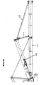
- a mobile crane 10 is shown with a main boom 12, wherein the main boom 12 consists of a lower boom portion 14 and an upper boom portion 16 which are pivotally connected to each other about a pivot point 18.
- the entire boom length of the main boom 12 is constructed on the ground.
- This main boom has a special intermediate piece, which is provided with a knee joint and a pressure link and is installed instead of a standard intermediate piece. The installation of this intermediate piece can be made at any point of the boom.
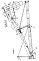
- Figure 5 shows that at the upper part of the main boom 16, a pressure arm 20 is provided which is pivotable about a pivot point 22 relative to the upper arm 16.
- the push rod 20 is a little raised when erecting the main boom with an auxiliary crane 24 from the transport position until there is a lever arm with respect to the pivot point 22.
- a foldout Support 26 By a foldout Support 26, the pressure arm 20 is held in this position.
- two rollers 28 and 30 are arranged.
- an auxiliary winch 32 is provided, via which an auxiliary cable 34 is withdrawn and shown in the backward order, as shown in phantom in Figure 5 partially to a hoist winch 36.
- the auxiliary cable 34 is coupled to the hoist rope wound on the hoist winch.
- the hoist rope is then pulled forward by means of the auxiliary rope 34 to a fixed point 38 near the top of the upper part 16 of the main boom 12.
- the hoisting rope is bolted to the fixed point 38.
- FIG. 6 shows the erection process of the pressure link 20.
- the pressure arm 20 By winding the hoist rope on the hoist winch 36, the pressure arm 20 automatically adjusts itself and tensioned front bracing rods 40.
- a Verstellwinde 42 On the main boom 12, a Verstellwinde 42 is arranged, with an adjusting bottle 44 is connected.
- the upper adjusting cylinder 48 By unwinding an adjusting cable 46 from the adjusting winch 42 and simultaneously winding the hoist winch 36, the upper adjusting cylinder 48 is pulled to the tip of the pressure arm until a bolt 50 provided on the upper adjusting cylinder 48 engages in a hook 52 (see FIG. 7 and in particular detail A) FIG. 7).
- the hook 52 can be lifted with a short auxiliary cable 54 (compare detail A to FIG. 7).
- the short auxiliary cable 54 is connected to the long auxiliary cable 34, so that the necessary force can be applied via the auxiliary winch 32.
Description
Die Erfindung betrifft einen Mobilkran mit einem langen Hauptauslegernach dem Oberbegriff des Anspruchs 1.The invention relates to a mobile crane with a long main boom according to the preamble of claim 1.
Durch spezielle Anwendungsgebiete werden immer längere Ausleger bei Mobilkranen gefordert. So besteht insbesondere beim Errichten von Windkraftanlagen das Problem, dass sehr lange Ausleger aufgerichtet werden müssen. Üblicherweise werden derartige Ausleger mit einem angebauten Derrickausleger mit angehängtem Derrickbalast aufgerichtet. Dies ist jedoch sehr zeitaufwendig und in schwierigem Gelände, in welchem Windkraftanlagen häufig stehen, schwer durchführbar.Due to special fields of application, ever longer booms are required for mobile cranes. Thus, in particular, when erecting wind turbines has the problem that very long boom must be erected. Usually, such booms are erected with a mounted derrick boom with attached derrick balustrade. However, this is very time consuming and hard to perform in difficult terrain where wind turbines are often.
Grundsätzlich ist es bereits bekannt, Hauptausleger mit wippbaren Gitterspitzen zu versehen. Bei derartigen Wippspitzen müssen Rückhaltesicherungen vorgesehen werden. Im übrigen befinden sie sich nach Aufrichten des Hauptauslegers meist in einer gegenüber dem Hauptausleger abgeknickten Lage.Basically, it is already known to provide main boom with luffing grid tips. In such tipping tips retention braces must be provided. Moreover, they are usually after erecting the main boom in a bent relative to the main boom position.
Ein Mobilkran mit einem langen Hauptausleger entsprechend dem Oberbegriff des Anspruchs 1 ist bereits aus der DE 101 07 389 A bekannt.A mobile crane with a long main boom according to the preamble of claim 1 is already known from DE 101 07 389 A.
Aufgabe der vorliegenden Erfindung ist es nun, Hauptausleger mit großen Auslegerlängen ohne Derrickausleger aufrichten zu können, wodurch der gesamte Aufrichtvorgang erleichtert wird und insbesondere lange Hauptausleger aufrichtbar sind.Object of the present invention is now to be able to erect main boom with long boom lengths without derrick boom, whereby the entire erection process is facilitated and in particular long main boom can be erected.
Erfindungsgemäß wird diese Aufgabe durch die Merkmale des Anspruchs 1 gelöst. Der zweigeteilte Hauptausleger ist in einem Schwenkpunkt derart miteinander verbunden, dass er beim Aufrichten abknickbar ist, um in eine gestreckte oder nahezu gestreckte Endmontagelage verbringbar zu sein, wobei am Hauptausleger mindestens ein Drucklenker um einen Schwenkpunkt schwenkbar angeordnet ist und wobei eine Verstellwinde vorgesehen ist, deren zugehörige Verstellflasche über eine Einscherung des Hubseils zur Spitze des Drucklenkers ziehbar ist, wo sie über einen Haken festlegbar ist. Dieser aufgerichtete Hauptausleger benötigt keine Rückhaltesicherung.According to the invention, this object is solved by the features of claim 1. The two-part main boom is connected at a pivot point such that it is bendable when erecting to be brought into a stretched or almost elongated final assembly position, wherein the main boom at least one pressure arm is pivotally mounted about a pivot point and wherein a Verstellwinde is provided associated adjusting bottle can be pulled over a reeving of the hoist cable to the top of the push rod, where it can be fixed by a hook. This erected main boom does not require retention.
Das Zwischenstück mit dem mindestens einen Drucklenker kann an einer beliebigen Stelle des Auslegers angeordnet sein. Am Drucklenker kann eine ausklappbare Stütze angelenkt sein. Der Mobilkran kann über eine Hilfswinde verfügen, über die ein Hilfsseil ab- bzw. aufwickelbar ist.The intermediate piece with the at least one pressure link can be arranged at any point of the boom. At the push handle a fold-out support can be hinged. The mobile crane may have an auxiliary winch, over which an auxiliary rope can be unwound or wound up.
Über die Verstellwinde kann die Verstellflasche zum aufrichten des abgeknickten vorderen Hauptauslegerteils einziehbar sein.About the adjusting the adjusting bottle can be retractable for erecting the bent front main boom part.
Vorzugsweise können zwei Drucklenker parallel zueinander angeordnet sein.Preferably, two pressure arms can be arranged parallel to each other.
Die Schwenkachsen der beiden Drucklenker können schräg zum Hauptausleger angeordnet sein, wobei durch die schräge Anordnung der Schwenkachsen der beiden Drucklenker eine seitliche Abspannung erreicht werden kann, wodurch die Seitenstabilität des Auslegers weiter erhöht wird.The pivot axes of the two pressure arms may be arranged obliquely to the main boom, wherein a lateral bracing can be achieved by the oblique arrangement of the pivot axes of the two pressure arms, whereby the lateral stability of the boom is further increased.
Weitere Einzelheiten und Vorteile der Erfindung werden an Hand eines in der Zeichnung dargestellten Ausführungsbeispieles näher erläutert. Es zeigen:
- Fig. 1:
- eine seitliche Darstellung eines Mobilkrans gemäß der vorliegenden Erfindung mit einem noch auf dem Boden aufliegenden Hauptausleger,
- Fig. 2 bis Fig. 4:
- verschiedene Arbeitsabschnitte während des Aufrichtens des Hauptauslegers in einer Ausführungsform, wie sie in Figur 1 dargestellt ist,
- Fig. 5 bis Fig. 7:
- Details während des Aufstellvorgangs des Mobilkrans.
- Fig. 1:
- a side view of a mobile crane according to the present invention with a still resting on the ground main boom,
- 2 to 4:
- various working sections during erection of the main boom in an embodiment as shown in Figure 1,
- Fig. 5 to Fig. 7:
- Details during the installation process of the mobile crane.
In Figur 1 ist ein Mobilkran 10 mit einem Hauptausleger 12 dargestellt, wobei der Hauptausleger 12 aus einem unteren Auslegerteil 14 und einem oberen Auslegerteil 16 besteht, die um einen Anlenkpunkt 18 schwenkbar miteinander verbunden sind. In der Figur 1 ist die gesamte Auslegerlänge des Hauptauslegers 12 auf dem Boden aufgebaut. Dieser Hauptausleger weist ein spezielles Zwischenstück auf, das mit einem Knie-Gelenk und einem Drucklenker versehen ist und an Stelle eines Standardzwischenstückes eingebaut ist. Der Einbau dieses Zwischenstücks kann an beliebiger Stelle des Auslegers vorgenommen werden.In Figure 1, a
An Hand der Figuren 5 bis 7 wird der Aufbau des Auslegers und der Komponenten des Mobilkrans 10, die zum Aufrichten des Hauptauslegers 12 notwendig sind, in näherem Detail beschrieben.With reference to Figures 5 to 7, the structure of the boom and the components of the
So zeigt Figur 5, dass am oberen Teil des Hauptauslegers 16 ein Drucklenker 20 vorgesehen ist, der um einen Anlenkpunkt 22 gegenüber dem oberen Ausleger 16 verschwenkbar ist. Der Drucklenker 20 wird beim Aufrichten des Hauptauslegers mit einem Hilfskran 24 aus der Transportstellung ein wenig angehoben, bis sich bezüglich des Anlenkpunktes 22 ein Hebelarm ergibt. Durch eine ausklappbare Stütze 26 wird der Drucklenker 20 in dieser Position gehalten. An der Spitze des Drucklenkers 20 sind zwei Rollen 28 und 30 angeordnet.Thus, Figure 5 shows that at the upper part of the
Am Mobilkran 10 ist eine Hilfswinde 32 vorgesehen, über die ein Hilfsseil 34 abgezogen wird und in rückwärtiger Folge, wie in Figur 5 teilweise gestrichelt dargestellt bis hin zu einer Hubwinde 36 geführt wird. Dort wird das Hilfsseil 34 mit dem auf der Hubwinde aufgewickelten Hubseil gekoppelt. Mit der Hilfswinde 32 wird anschließend mittels des Hilfsseils 34 das Hubseil nach vorne gezogen bis zu einem Festpunkt 38 nahe der Spitze des oberen Teils 16 des Hauptauslegers 12. Dort wird das Hubseil mit dem Festpunkt 38 verbolzt.On
In Figur 6 wird der Aufrichtvorgang des Drucklenkers 20 gezeigt. Durch Aufspulen des Hubseils auf der Hubwinde 36 richtet sich der Drucklenker 20 selbsttätig auf und spannt vordere Abspannstangen 40. Am Hauptausleger 12 ist eine Verstellwinde 42 angeordnet, mit der eine Verstellflasche 44 verbunden ist. Durch Abspulen eines Verstellseils 46 von der Verstellwinde 42 und gleichzeitiges Aufspulen der Hubwinde 36 wird die obere Verstellflasche 48 zur Spitze des Drucklenkers gezogen, bis ein an der oberen Verstellflasche 48 vorgesehener Bolzen 50 in einem Haken 52 einrastet (vergleiche Figur 7 und insbesondere Detail A zur Figur 7).FIG. 6 shows the erection process of the
Zur Demontage kann der Haken 52 mit einem kurzen Hilfsseil 54 (vergleiche Detail A zur Figur 7) angehoben werden. Hierzu wird das kurze Hilfsseil 54 mit dem langen Hilfsseil 34 verbunden, so dass die notwendige Kraft über die Hilfswinde 32 aufbringbar ist.For disassembly, the
Beim Aufrichten des Hauptauslegers, wie dies in den Figuren 2 bis 4 gezeigt ist, wird nun zunächst der untere Teil 14 des Hauptauslegers hochgezogen (vergleiche Figur 2). Hierbei rollt die Spitze des oberen Teil des Auslegers 16 auf den Boden ab oder wird mit einem Hilfskran in der Schwebe gehalten. Während des Aufrichtens des unteren Teils 14 des Hauptauslegers 12 wird die Verstellflasche 44 laufend nachgelassen, so dass das Auslegerkopfgewicht auf dem Boden aufliegt und deshalb nicht mitaufgerichtet werden muss. Nachdem der untere Teil des Hauptauslegers einen entsprechenden Winkel zum Boden erreicht hat und demzufolge die Massen näher zum Kran verlagert wurden, wird über das Einziehen der Verstellflasche 44 mittels der Verstellwinde 42 der obere Teil 16 des Hauptauslegers hochgezogen. Der Hauptausleger befindet sich dabei immer noch in einer Neigung nach vorne, so dass der Ausleger in eine Streckposition gebracht werden kann, ohne das eine Rückhaltesicherung erforderlich ist. Der Ausleger wird bis auf einen Anschlag gezogen und die Verstellflasche 44 wird festgesetzt. Durch diese zusätzliche Rückspannung wird die Stabilität des Auslegers 10 noch erhöht.When erecting the main boom, as shown in Figures 2 to 4, the
Claims (6)
- Mobile crane (10) with a long main boom (12) which is in two parts and is connected together at a pivot point (18) in such a manner that it can be bent over as it is erected in order to be able to be placed into an extended or virtually extended final assembly position, characterized in that at least one strut member (20) is arranged on the main boom (12) in a manner such that it can pivot about a pivot point (22), and in that an adjustment winch (42) is provided, the associated adjustment pulley (44) of which can be pulled to the tip of the strut member (20) by a reeving of the hoisting cable, with it being able to be secured via a hook (52).
- Mobile crane according to Claim 1, characterized in that a support (26) which can be opened out is coupled to the strut member (20).
- Mobile crane according to either of Claims 1 and 2, characterized in that an auxiliary winch (32) is provided via which an auxiliary cable (34) can be unwound and wound up.
- Mobile crane according to one of Claims 1-3, characterized in that two strut members (20) are arranged parallel to each other.
- Mobile crane according to Claim 4, characterized in that the pivot axes of the two strut members (20) are arranged obliquely with respect to the main boom.
- Mobile crane according to either of Claims 4 and 5, characterized in that the adjustment pulley (44) can be retracted via the adjustment winch (42) in order to erect the bent-over front main boom part (16).
Applications Claiming Priority (2)
| Application Number | Priority Date | Filing Date | Title |
|---|---|---|---|
| DE20218971U | 2002-12-06 | ||
| DE20218971U DE20218971U1 (en) | 2002-12-06 | 2002-12-06 | Mobile crane with long arms |
Publications (2)
| Publication Number | Publication Date |
|---|---|
| EP1426321A1 EP1426321A1 (en) | 2004-06-09 |
| EP1426321B1 true EP1426321B1 (en) | 2006-05-31 |
Family
ID=32103537
Family Applications (1)
| Application Number | Title | Priority Date | Filing Date |
|---|---|---|---|
| EP03022158A Expired - Lifetime EP1426321B1 (en) | 2002-12-06 | 2003-09-30 | Mobile crane with two part boom |
Country Status (3)
| Country | Link |
|---|---|
| US (1) | US7219810B2 (en) |
| EP (1) | EP1426321B1 (en) |
| DE (2) | DE20218971U1 (en) |
Families Citing this family (10)
| Publication number | Priority date | Publication date | Assignee | Title |
|---|---|---|---|---|
| CA2520847A1 (en) * | 2003-04-02 | 2004-10-14 | Terex-Demag Gmbh & Co. Kg | Two-piece main boom for a latice-boom crane and method for erection thereof |
| DE202005016743U1 (en) * | 2005-10-25 | 2007-03-29 | Liebherr-Werk Ehingen Gmbh | Crane comprises a bracing device having two brace supports hinged on an auxiliary boom and inclined opposite a rocker surface |
| DE102007056289B4 (en) | 2007-10-29 | 2009-06-04 | Liebherr-Werk Ehingen Gmbh | Method for erecting a crane jib |
| US8839966B2 (en) | 2009-03-31 | 2014-09-23 | Manitowoc Crane Companies, Llc | Folding jib main strut and transportable reeved strut caps |
| EP2476642B1 (en) * | 2011-01-12 | 2013-07-24 | Manitowoc Crane Companies, LLC | Method of connecting crane suspension assembly sections together and frame mounted assembly used therefore |
| DE102011014585A1 (en) * | 2011-03-21 | 2012-09-27 | Liebherr-Werk Ehingen Gmbh | Method for erecting beam of crane, particularly for erecting lattice jib, involves erecting beam from laid down position, in which traction force is exerted on beam by traction element, particularly restraint |
| DE102012019248A1 (en) * | 2012-09-28 | 2014-04-03 | Liebherr-Werk Biberach Gmbh | Tower Crane |
| DE102013002415B4 (en) | 2013-02-11 | 2019-04-25 | Liebherr-Werk Ehingen Gmbh | Method for erecting a long boom and crane |
| CN103708362B (en) * | 2013-12-27 | 2015-12-09 | 浙江三一装备有限公司 | Articulated boom and hoisting crane in a kind of crawler crane |
| CN116443745B (en) * | 2023-06-16 | 2023-10-20 | 杭州未名信科科技有限公司 | Tower crane system and control method |
Family Cites Families (20)
| Publication number | Priority date | Publication date | Assignee | Title |
|---|---|---|---|---|
| DE339191C (en) * | 1920-06-01 | 1921-07-16 | Maschf Augsburg Nuernberg Ag | Mobile railway crane |
| US3028018A (en) * | 1959-05-08 | 1962-04-03 | Alfred H Mott | Collapsible boom for mobile cranes |
| US3173549A (en) * | 1962-03-22 | 1965-03-16 | Emil A Bender | Material handling device |
| GB981129A (en) * | 1962-10-05 | 1965-01-20 | John Allen & Sons Oxford Ltd | Improvements relating to crane booms |
| US3209920A (en) * | 1964-02-12 | 1965-10-05 | T S Decuir | Combination crane |
| US3426915A (en) * | 1967-08-28 | 1969-02-11 | Caterpillar Tractor Co | Collapsible weight handling boom |
| FR2152491B1 (en) * | 1971-09-15 | 1977-07-08 | ||
| US3804264A (en) * | 1972-12-08 | 1974-04-16 | Harnischfeger Corp | Tower crane with rockable top sector |
| US4068762A (en) * | 1975-09-11 | 1978-01-17 | Kennard Jr Dwight Clinton | Pickup truck derrick |
| FR2409225A1 (en) * | 1977-11-21 | 1979-06-15 | Creusot Loire | IMPROVEMENT WITH TELESCOPIC CRANES |
| US4194638A (en) * | 1978-06-07 | 1980-03-25 | The Manitowoc Company, Inc. | Ring supported tower crane |
| US4383616A (en) * | 1980-12-24 | 1983-05-17 | Kidde, Inc. | Luffing jib for construction crane |
| US5292016A (en) * | 1992-10-08 | 1994-03-08 | The Manitowoc Company | Luffing jib backstop assembly |
| EP0970914B1 (en) * | 1998-07-07 | 2009-03-18 | Terex Demag GmbH | Mobile crane with telescopic jib |
| DE20023565U1 (en) * | 1999-06-28 | 2004-11-25 | Terex-Demag Gmbh & Co. Kg | telescopic crane |
| DE10022600B4 (en) * | 1999-06-28 | 2007-09-27 | Terex-Demag Gmbh & Co. Kg | telescopic crane |
| DE20107984U1 (en) * | 2000-04-28 | 2001-12-06 | Demag Mobile Cranes Gmbh | Mobile crane with luffing jib |
| JP2002060183A (en) * | 2000-08-10 | 2002-02-26 | Hitachi Constr Mach Co Ltd | Hydraulic crane |
| ITMI20010116A1 (en) * | 2001-01-23 | 2002-07-23 | San Marco Internat S R L | TOWER CRANE WITH SELF-ASSEMBLING STRUCTURE WITH FOLDABLE AND REMOVABLE TOWER AND ARM WITH MULTIPLE PORTIONS |
| DE10107389A1 (en) * | 2001-02-07 | 2002-08-22 | Atecs Mannesmann Ag | Device for erecting a luffing support of a crane |
-
2002
- 2002-12-06 DE DE20218971U patent/DE20218971U1/en not_active Expired - Lifetime
-
2003
- 2003-09-30 EP EP03022158A patent/EP1426321B1/en not_active Expired - Lifetime
- 2003-09-30 DE DE50303557T patent/DE50303557D1/en not_active Expired - Lifetime
- 2003-12-08 US US10/730,402 patent/US7219810B2/en active Active
Also Published As
| Publication number | Publication date |
|---|---|
| DE20218971U1 (en) | 2004-04-08 |
| EP1426321A1 (en) | 2004-06-09 |
| DE50303557D1 (en) | 2006-07-06 |
| US7219810B2 (en) | 2007-05-22 |
| US20040124167A1 (en) | 2004-07-01 |
Similar Documents
| Publication | Publication Date | Title |
|---|---|---|
| EP2055665B1 (en) | Method for erecting a crane boom | |
| DE102005049606B4 (en) | Mobile crane with additional boom and procedure for disassembling the jib | |
| EP1900675B1 (en) | Crane truck | |
| EP1428788B1 (en) | Telescopic jib | |
| EP2067737B1 (en) | Side bracing for a grid extension of a crane | |
| EP1426321B1 (en) | Mobile crane with two part boom | |
| DE2950884A1 (en) | MOBILE CRANE | |
| DE102018115632B3 (en) | Telescopic boom bracing device | |
| DE202007008990U1 (en) | Telescopic boom of a crane | |
| DE202005016743U1 (en) | Crane comprises a bracing device having two brace supports hinged on an auxiliary boom and inclined opposite a rocker surface | |
| DE19730361B4 (en) | mobile crane | |
| DE3633582C2 (en) | ||
| DE2755986A1 (en) | LIFTING SYSTEM FOR A CRANE | |
| DE2908584C2 (en) | Mobile crane | |
| DE1456490A1 (en) | Tower crane vehicle | |
| DE202004013077U1 (en) | Vehicle crane for lifting objects has base arm, which is detachably connected to main arm whereby one or two tightening supports are arranged on base arm | |
| DE102019122071B3 (en) | Telescopic boom with fold-out mast | |
| EP1084983A1 (en) | Tower crane | |
| WO2021170394A1 (en) | Crane comprising counterjib, and method for erecting the counterjib | |
| DE8234374U1 (en) | Tower crane | |
| WO2021104999A1 (en) | Crane comprising a tiltable jib extension, and method for assembling a luffing jib | |
| DE2647535A1 (en) | CRANE CONSTRUCTION | |
| AT526450A2 (en) | Mobile crane with a detachable attached superstructure and setup process for this | |
| EP1847409A1 (en) | Truck with cover system | |
| DE2045112A1 (en) | Mobile crane with telescopic boom |
Legal Events
| Date | Code | Title | Description |
|---|---|---|---|
| PUAI | Public reference made under article 153(3) epc to a published international application that has entered the european phase |
Free format text: ORIGINAL CODE: 0009012 |
|
| AK | Designated contracting states |
Kind code of ref document: A1 Designated state(s): AT BE BG CH CY CZ DE DK EE ES FI FR GB GR HU IE IT LI LU MC NL PT RO SE SI SK TR |
|
| AX | Request for extension of the european patent |
Extension state: AL LT LV MK |
|
| 17P | Request for examination filed |
Effective date: 20040512 |
|
| 17Q | First examination report despatched |
Effective date: 20041014 |
|
| AKX | Designation fees paid |
Designated state(s): DE FR GB |
|
| GRAP | Despatch of communication of intention to grant a patent |
Free format text: ORIGINAL CODE: EPIDOSNIGR1 |
|
| GRAS | Grant fee paid |
Free format text: ORIGINAL CODE: EPIDOSNIGR3 |
|
| GRAA | (expected) grant |
Free format text: ORIGINAL CODE: 0009210 |
|
| AK | Designated contracting states |
Kind code of ref document: B1 Designated state(s): DE FR GB |
|
| REG | Reference to a national code |
Ref country code: GB Ref legal event code: FG4D Free format text: NOT ENGLISH |
|
| REF | Corresponds to: |
Ref document number: 50303557 Country of ref document: DE Date of ref document: 20060706 Kind code of ref document: P |
|
| GBT | Gb: translation of ep patent filed (gb section 77(6)(a)/1977) |
Effective date: 20060824 |
|
| ET | Fr: translation filed | ||
| PLBE | No opposition filed within time limit |
Free format text: ORIGINAL CODE: 0009261 |
|
| STAA | Information on the status of an ep patent application or granted ep patent |
Free format text: STATUS: NO OPPOSITION FILED WITHIN TIME LIMIT |
|
| 26N | No opposition filed |
Effective date: 20070301 |
|
| PGFP | Annual fee paid to national office [announced via postgrant information from national office to epo] |
Ref country code: GB Payment date: 20130925 Year of fee payment: 11 |
|
| GBPC | Gb: european patent ceased through non-payment of renewal fee |
Effective date: 20140930 |
|
| PG25 | Lapsed in a contracting state [announced via postgrant information from national office to epo] |
Ref country code: GB Free format text: LAPSE BECAUSE OF NON-PAYMENT OF DUE FEES Effective date: 20140930 |
|
| REG | Reference to a national code |
Ref country code: FR Ref legal event code: PLFP Year of fee payment: 14 |
|
| PGFP | Annual fee paid to national office [announced via postgrant information from national office to epo] |
Ref country code: FR Payment date: 20160923 Year of fee payment: 14 |
|
| REG | Reference to a national code |
Ref country code: FR Ref legal event code: ST Effective date: 20180531 |
|
| PG25 | Lapsed in a contracting state [announced via postgrant information from national office to epo] |
Ref country code: FR Free format text: LAPSE BECAUSE OF NON-PAYMENT OF DUE FEES Effective date: 20171002 |
|
| PGFP | Annual fee paid to national office [announced via postgrant information from national office to epo] |
Ref country code: DE Payment date: 20220606 Year of fee payment: 20 |
|
| P01 | Opt-out of the competence of the unified patent court (upc) registered |
Effective date: 20230607 |
|
| REG | Reference to a national code |
Ref country code: DE Ref legal event code: R071 Ref document number: 50303557 Country of ref document: DE |