EP1425872B1 - Procédé et système de communication permettant d'établir au moins une liaison de communication à securité integrée - Google Patents
Procédé et système de communication permettant d'établir au moins une liaison de communication à securité integrée Download PDFInfo
- Publication number
- EP1425872B1 EP1425872B1 EP02774363A EP02774363A EP1425872B1 EP 1425872 B1 EP1425872 B1 EP 1425872B1 EP 02774363 A EP02774363 A EP 02774363A EP 02774363 A EP02774363 A EP 02774363A EP 1425872 B1 EP1425872 B1 EP 1425872B1
- Authority
- EP
- European Patent Office
- Prior art keywords
- communication
- functions
- access unit
- access
- communication link
- Prior art date
- Legal status (The legal status is an assumption and is not a legal conclusion. Google has not performed a legal analysis and makes no representation as to the accuracy of the status listed.)
- Expired - Fee Related
Links
- 238000004891 communication Methods 0.000 title claims abstract description 138
- 238000000034 method Methods 0.000 title claims description 21
- 230000005540 biological transmission Effects 0.000 claims abstract description 99
- 230000001360 synchronised effect Effects 0.000 claims description 4
- 238000012544 monitoring process Methods 0.000 claims 3
- 238000003745 diagnosis Methods 0.000 claims 2
- 101100053833 Schizosaccharomyces pombe (strain 972 / ATCC 24843) zfs1 gene Proteins 0.000 claims 1
- 230000010354 integration Effects 0.000 description 7
- 230000000694 effects Effects 0.000 description 5
- 230000002950 deficient Effects 0.000 description 4
- RGNPBRKPHBKNKX-UHFFFAOYSA-N hexaflumuron Chemical compound C1=C(Cl)C(OC(F)(F)C(F)F)=C(Cl)C=C1NC(=O)NC(=O)C1=C(F)C=CC=C1F RGNPBRKPHBKNKX-UHFFFAOYSA-N 0.000 description 4
- 230000000712 assembly Effects 0.000 description 2
- 238000000429 assembly Methods 0.000 description 2
- 230000008901 benefit Effects 0.000 description 2
- 238000010586 diagram Methods 0.000 description 2
- 230000003213 activating effect Effects 0.000 description 1
- 238000010276 construction Methods 0.000 description 1
- 230000009849 deactivation Effects 0.000 description 1
- 230000007547 defect Effects 0.000 description 1
- 238000002955 isolation Methods 0.000 description 1
- 230000007246 mechanism Effects 0.000 description 1
- 230000008569 process Effects 0.000 description 1
- 230000008439 repair process Effects 0.000 description 1
Images


Classifications
-
- H—ELECTRICITY
- H04—ELECTRIC COMMUNICATION TECHNIQUE
- H04L—TRANSMISSION OF DIGITAL INFORMATION, e.g. TELEGRAPHIC COMMUNICATION
- H04L41/00—Arrangements for maintenance, administration or management of data switching networks, e.g. of packet switching networks
- H04L41/06—Management of faults, events, alarms or notifications
- H04L41/0654—Management of faults, events, alarms or notifications using network fault recovery
- H04L41/0663—Performing the actions predefined by failover planning, e.g. switching to standby network elements
-
- H—ELECTRICITY
- H04—ELECTRIC COMMUNICATION TECHNIQUE
- H04J—MULTIPLEX COMMUNICATION
- H04J3/00—Time-division multiplex systems
- H04J3/02—Details
- H04J3/14—Monitoring arrangements
-
- H—ELECTRICITY
- H04—ELECTRIC COMMUNICATION TECHNIQUE
- H04L—TRANSMISSION OF DIGITAL INFORMATION, e.g. TELEGRAPHIC COMMUNICATION
- H04L1/00—Arrangements for detecting or preventing errors in the information received
- H04L1/22—Arrangements for detecting or preventing errors in the information received using redundant apparatus to increase reliability
-
- H—ELECTRICITY
- H04—ELECTRIC COMMUNICATION TECHNIQUE
- H04L—TRANSMISSION OF DIGITAL INFORMATION, e.g. TELEGRAPHIC COMMUNICATION
- H04L41/00—Arrangements for maintenance, administration or management of data switching networks, e.g. of packet switching networks
- H04L41/06—Management of faults, events, alarms or notifications
- H04L41/0677—Localisation of faults
-
- H—ELECTRICITY
- H04—ELECTRIC COMMUNICATION TECHNIQUE
- H04L—TRANSMISSION OF DIGITAL INFORMATION, e.g. TELEGRAPHIC COMMUNICATION
- H04L69/00—Network arrangements, protocols or services independent of the application payload and not provided for in the other groups of this subclass
- H04L69/40—Network arrangements, protocols or services independent of the application payload and not provided for in the other groups of this subclass for recovering from a failure of a protocol instance or entity, e.g. service redundancy protocols, protocol state redundancy or protocol service redirection
-
- H—ELECTRICITY
- H04—ELECTRIC COMMUNICATION TECHNIQUE
- H04L—TRANSMISSION OF DIGITAL INFORMATION, e.g. TELEGRAPHIC COMMUNICATION
- H04L9/00—Cryptographic mechanisms or cryptographic arrangements for secret or secure communications; Network security protocols
- H04L9/40—Network security protocols
-
- H—ELECTRICITY
- H04—ELECTRIC COMMUNICATION TECHNIQUE
- H04J—MULTIPLEX COMMUNICATION
- H04J2203/00—Aspects of optical multiplex systems other than those covered by H04J14/05 and H04J14/07
- H04J2203/0001—Provisions for broadband connections in integrated services digital network using frames of the Optical Transport Network [OTN] or using synchronous transfer mode [STM], e.g. SONET, SDH
- H04J2203/0028—Local loop
- H04J2203/0039—Topology
- H04J2203/0041—Star, e.g. cross-connect, concentrator, subscriber group equipment, remote electronics
-
- H—ELECTRICITY
- H04—ELECTRIC COMMUNICATION TECHNIQUE
- H04J—MULTIPLEX COMMUNICATION
- H04J2203/00—Aspects of optical multiplex systems other than those covered by H04J14/05 and H04J14/07
- H04J2203/0001—Provisions for broadband connections in integrated services digital network using frames of the Optical Transport Network [OTN] or using synchronous transfer mode [STM], e.g. SONET, SDH
- H04J2203/0057—Operations, administration and maintenance [OAM]
- H04J2203/006—Fault tolerance and recovery
-
- H—ELECTRICITY
- H04—ELECTRIC COMMUNICATION TECHNIQUE
- H04L—TRANSMISSION OF DIGITAL INFORMATION, e.g. TELEGRAPHIC COMMUNICATION
- H04L69/00—Network arrangements, protocols or services independent of the application payload and not provided for in the other groups of this subclass
- H04L69/14—Multichannel or multilink protocols
Definitions
- Method and communication device for implementing at least one fail-safe communication relationship by a communication device arranged in a communication network.
- DE 198 31 562 discloses, for example, the principle of line redundancy in accordance with the Synchronous Digital Hierarchy configured communication networks or in Sonet transmission networks, which is to be protected from failure with the help of line redundancy of the data traffic to be transmitted on the lines.
- a redundant transmission path is provided by a second line, which can take over the data traffic of the originally used data line in the event of an error.
- Widely used is the so-called 1 + 1 line redundancy, in which at the transmitting end of the transmission line the traffic to be transmitted via a so-called bridge on both lines can be sent approximately simultaneously and at the receiving end via a so-called “selector" the traffic of one of the two Lines can be selected for further processing.
- the document EP1128546 discloses a device having a plurality of redundant terminal units and a plurality of redundant transmission lines which enable an equivalent circuit in the event of a failure of a terminal unit. A changeover between a terminal unit and a terminal unit redundant to it takes place by the control control of the central control unit.
- a second module is provided and assigned to the first module, which can take over the functions of the originally used module in the event of an error.
- Line and module redundancy can be combined according to the above-mentioned publication.
- the equivalent circuit of the data line and the interface module is coupled together.
- a replacement of the line automatically leads to the replacement of the interface module and vice versa.
- This method is particularly used in large communication devices that are connected to a larger number of transmission lines.
- These communication devices have, in addition to the interface assemblies, subassemblies that perform central functions of the communication device, e.g. Switching functions or central control functions.
- These modules can also be secured against module failure with module redundancy.
- the module redundancy of the central modules is not coupled with the module redundancy of the interface module or the line redundancy.
- FIG. 1 shows a block diagram of a communication device in which line and module redundancy are implemented.
- the line redundancy and the module redundancy of the interface module are coupled with each other.
- the outgoing from the communication device data stream is performed by means of a bridge over both interface modules on both outgoing lines, while from the guided via the interface module incoming data streams by means of the selector in the communication device further to be processed data stream is selected.
- the central control function of this communication device is executed separately from the interface modules and lines, but may also be redundant. In an equivalent circuit of the lines and the interface modules, the central control function is not switched. In an equivalent circuit of the central control function lines and interface modules are not affected. The same applies to other, in each case realized in the communication device central functions, such as the switching function.
- the high level of integration also leads to the integration of central functions of the communication device with central transmission interfaces shared by many subscribers.
- the transmission interface is integrated on a module together with the transmission interface leading to the central communication network and central functions of the communication device.
- the invention has the object to realize a line and module redundancy for a communication device, in which the transmission interface of the transmission line and the central control functions are integrated on a module or terminal unit.
- the object is achieved on the basis of a method and a communication device according to the preambles of claims 1 and 9 by their characterizing features.
- connection units arranged in the communication device, to each of which one of a plurality of redundant transmission lines provided for realizing the at least one communication relationship is connected.
- connection units are control functions for the control of centrally in the communication device realized, communication device-specific functions and / or provided in the respective connection unit connection unit specific functions provided.
- the essential aspect of the method according to the invention is that if at least part of the control functions in one of the connection units fails, at least the failed communication device-specific and / or connection-unit-specific functions are controlled by the control functions of the at least one assigned connection unit.
- the essential advantage of the method according to the invention is that in communication networks or communication devices, which are arranged for example in the subscriber line area - also known as Digital Subscriber Line Access Multiplexer DSLAM - in a cost-effective manner fail-safe transmission interfaces to the central communication network and central functions of the communication devices on a module or Connection unit can be integrated.
- the central functions may include control functions, switching functions, timing and synchronizing devices, management interfaces, etc., or sub-functions of one or more of these functions.
- FIG. 4 shows in a block diagram a communication device KE arranged in a communication network, for example an SDH communication network, in which the inventive independence of line and module redundancy is fulfilled.
- a communication network for example an SDH communication network
- the transmission lines ÜL1, ÜL3 or ÜL2, ÜL4 form a pair with regard to the line redundancy and with regard to the respective communication relationship kb1,2 to be realized.
- first and third transmission lines ÜL1,2 are connected to a first further communication device Z1 and the second and fourth transmission lines ÜL2,4 are connected to a second further communication device Z2 - shown in FIG.
- redundantly executed central control functions zsf1 or zsf2 are implemented in the communication device KE, wherein these redundantly executed control functions zsf1, 2 are likewise arranged on the different central connection units AE1, 2.
- This central Control functions zsf1, zsf2 are executed by a control unit STE or by a processor, which can also execute local control functions on the respective connection unit AE1, 2, such as control functions for the transmission interfaces ÜSS1, 2 or ÜSS3, 4.
- the central control functions zsf1, 2 are connected to each other via a communication link KV, via which the sequence of the equivalent circuit can be coordinated and can be synchronized with each other via the central control functions zsf1, 2.
- the communication link KV contains both hardware-dominant components for time-critical equivalent circuit procedures and for equivalent circuit cases in which software-controlled switching is no longer possible, as well as software-dominated components for less time-critical processes.
- the subscriber-side interfaces of the communication device such as xDSL interfaces or other transmission interfaces used for cascading are essential components of the communication device, which are not shown in FIG.
- the inventive redundancy architecture shown in FIG. 4 does not depend on the realization of the central switching function of the communication device.
- This redundancy architecture can be realized, for example, together with a bus-based switching architecture, a switching network-based or a star-shaped serial interface-based switching architecture.
- the switching architecture itself can also be of redundant construction and it can be parts of this switching architecture be integrated on the central terminal units AE1 and AE2.
- connection of the communication device with a TMN system can take place via a so-called “in-band connection”.
- TTN telecommunication management network
- the connection to the TMN system is conducted together with the remaining traffic as part of an "in-band connection” on the transmission lines.
- It can also be realized according to an "outband connection", wherein the communication device is connected to the TMN system via separate interfaces, for example an Ethernet interface. Both possibilities can be realized with the aid of the method according to the invention or with the redundancy architecture according to the invention.
- the central clock generator function for the communication device can likewise be integrated on the central connection unit AE1, 2.
- An equivalent circuit in the sense of line redundancy can take place in the event of a failure of a transmission line ÜL1.
- An equivalent circuit in the sense of module redundancy can take place in the event of a fault in the hardware or parts of the hardware of a connection unit BG1, 2 or in the case of a non-repairable software error in the central control function zsf1, 2.
- the redundancy of the central control function zsf1, 2 is thus part of the module redundancy.
- a hardware error on a module or connection unit AE1, 2 can also be an error in the hardware of a transmission interface ÜSS1 ... 4.
- the equivalent circuit of the central control function zsf1, 2 without simultaneous replacement circuit of the module or connection unit AE1, 2 in the event of an error which is unambiguously attributable to the central control function.
- the equivalent circuit of the transmission line ÜL1 ... 4 as a result of the equivalent circuit of the central control function of a connection unit AE1, 2 can be advantageously avoided here.
- the error of the central control function zsf1, 2 must not affect the functions required for the replacement of the central control function zsf1, 2 functions. In order to replace the defective module or connection unit AE1, 2, the equivalent circuit of the connection unit AE1, 2 may nevertheless be required later.
- first a first central control function zsf1, 2 is updated or loaded with new software, while the other, the active function of the control of the communication device KE takes over.
- the central control function can be switched over and the second central control function zsf2 can be loaded or updated with new software, while the first central control function zsf1 assumes the active function of controlling the communication device KE.
- a switchover of each of a connection unit AE1, 2 connected transmission lines ÜL1, 2 and ÜL3, 4 is not required.
- the central control function zsf1, 2 may e.g. be switched for test purposes with a manual changeover command.
- a switching of the transmission lines ÜL1, 2 or ÜL3, 4 is also not required.
- the measures to be implemented in the context of the line redundancy have no effects on a respective other transmission line connected to the respective connection unit AE1, 2. Furthermore, the measures to be implemented in the context of line redundancy have no effect on the module redundancy.
- module redundancy measures can include line redundancy measures.
- the central control function zsf1, 2 of a connection unit AE1, 2 can be switched independently of the line redundancy and the module redundancy.
- the equivalent circuit of a transmission line üL1 ... 4 in the case of a line fault and the equivalent circuit of a module or connection unit AE1, 2 in the case of a hardware error on the connection unit AE1, 2 and their effect on the other redundant functions will be illustrated with reference to two embodiments ,
- the state in which the active traffic selected by the selector is transmitted via a transmission line ÜL1... 4 is to be designated as the operating state "active".
- the redundant line ÜL1 ... 4 has in this Case the operating state "standby”.
- the active central control function zsf1, 2 should also be described with the status "active", while the redundant control function zsf1, 2 with the operating status "standby" should be described.
- the transmission lines ÜL1 and ÜL2 and the central connection unit AE1 are in the "active" state.
- the transmission lines ÜL1 ... 4 are, for example, STM-1 transmission lines designed according to the synchronous digital hierarchy (SDH), where ÜL1 and ÜL2 represent "working transmission lines” in the sense of SDH / Sonet line redundancy and the transmission lines ÜL3 and ÜL4 " protection lines ".
- SDH synchronous digital hierarchy
- An error on the transmission line ÜL1 with the operating state "active" is detected by the transmission interface ÜSS1 arranged on the first connection unit AE1.
- the local control function of the connection unit AE1 contained in the central control function zsf1 reports this error via the communication connection KV to the local control function contained in the central control function zsf2 of the second connection unit AE2.
- the equivalent circuit of the transmission lines is agreed and controlled with the device or communication device connected to the other end of the transmission lines ÜL1 and ÜL3 via the control protocol of the SDH / SONET line redundancy.
- the data traffic transmitted between the subscriber-side modules (not shown) and the first transmission line ÜL1 is switched to the transmission line ÜL3 by means of bridge and selector.
- the data traffic transmitted between the second transmission line ÜL2 and the first transmission line ÜL1 is also transmitted by means of bridge and Selector switched to a connection between the second and third transmission line ÜL2 and ÜL3.
- an equivalent circuit of the modules does not take place.
- the transmission lines ÜL3 and ÜL2 and the first connection unit AE1 are in the "active" state. Furthermore, the central control function zsf1 arranged in the first connection unit AE1 is in the "active" state. Furthermore, the conditions stated in Example 1 are also valid in this embodiment.
- the local control function of the first connection unit AE1 contained in the central control function zsf1 recognizes a hardware error on the first connection unit AE1 and reports this to the central control function zsf1.
- the central control function zsf1 transmits corresponding information about the hardware error via the communication connection KV to the central control function zsf2 arranged in the second connection unit AE2.
- the central control function zsf2 arranged in the second connection unit AE2 is informed that an assembly replacement circuit must take place, whereupon the central control function zsf2 carries out the replacement circuit.
- a controlled line replacement circuit for the transmission lines ÜL2 and ÜL4 can still be carried out before the module equivalent circuit.
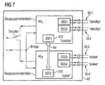
- connection units AE1, AE2 the hardware-dominated components of the communication connection KV mentioned in the exemplary embodiments will be explained in more detail between the first and second connection unit AE1, AE2.
- the following functions are to be provided via hardware-based interfaces between the connection units AE1 and AE2:
- the plugged-in connection unit can detect whether central system resources or system interfaces already exist before activating your communication interface to the active partner module or partner connection unit may be activated on the plugged connection unit.
- the redundant, active partner module or partner connection unit can initiate diagnostic functions for limiting errors in the system. By disabling the external interfaces of a defective module or connection unit, under certain sources of error, an isolation of the error state can be achieved, so that the conditions for an undisturbed or possibly limitedIESschalte legi too.
Landscapes
- Engineering & Computer Science (AREA)
- Computer Networks & Wireless Communication (AREA)
- Signal Processing (AREA)
- Computer Security & Cryptography (AREA)
- Data Exchanges In Wide-Area Networks (AREA)
- Maintenance And Management Of Digital Transmission (AREA)
- Telephonic Communication Services (AREA)
Abstract
Claims (14)
- Procédé pour réaliser au moins une relation de communication (KG1, 2) à sûreté intégrée par un dispositif de communication (KE) disposé dans un réseau de communication (KN), dans lequel plusieurs unités de raccordement (AE1, 2) disposées dans le dispositif de communication (KE) et attribuées les unes aux autres sont prévues, à chacune desquelles est raccordée une de plusieurs lignes de transmission (UL1 ... 4) redondantes, prévues pour la réalisation de l'au moins une relation de communication (KG1, 2), des informations spécifiques à la relation de communication étant transmises par l'une des lignes de transmission (UL1) redondantes, prévues respectivement pour la réalisation de l'au moins une relation de communication (KG1) et par l'unité de raccordement (AE1) reliée à cette ligne, dans lequel, dans chacune des unités de raccordement (AE1, 2), des fonctions de commande (zsf1, 2) sont prévues pour la commande de fonctions réalisées de façon centrale dans le dispositif de communication (KE) et spécifiques au dispositif de communication et de fonctions spécifiques à l'unité de raccordement et réalisées dans l'unité de raccordement respective,
caractérisé en ce que
les fonctions de commande (zsf1, 2) prévues dans les unités de raccordement (AE1, 2) attribuées entre elles sont exécutées de façon redondante les unes par rapport aux autres,
en ce que, en cas de défaillance d'au moins une partie des fonctions de commande (zsf1, 2) dans l'une des unités de raccordement (AE1), au moins les fonctions spécifiques au dispositif de communication et/ou spécifiques à l'unité de raccordement qui sont devenues défaillantes sont commandées par les fonctions de commande (zsf1, 2) de l'au moins une unité de raccordement (AE2) attribuée, les informations spécifiques à la relation de communication étant encore transmises par une ligne de transmission (UL1) et l'unité de raccordement (AE1) reliée à celle-ci. - Procédé selon la revendication 1,
caractérisé en ce que,
en cas de défaillance de la ligne de transmission (UL1...4) transmettant les informations dans le cadre de l'au moins une relation de communication (KG1, 2), les informations spécifiques à la relation de communication sont transmises par au moins une autre ligne de transmission (UL1 ... 4) redondante, prévue dans le cadre de cette relation de communication (KG1, 2) et de l'unité de raccordement (AE1, 2) reliée à l'au moins une autre ligne de transmission. - Procédé selon la revendication 1 ou 2,
caractérisé en ce que
les informations spécifiques à la relation de communication sont transmises par les unités de raccordement (AE1, 2) attribuées les unes aux autres et les lignes de transmission (UL1 ... 4) raccordées à celles-ci, dans le cadre de plusieurs liaisons de communication (KG1,2) réalisées approximativement simultanément. - Procédé selon la revendication 3,
caractérisé en ce que,
en cas de défaillance d'au moins une partie des fonctions spécifiques à l'unité de raccordement dans l'une des unités de raccordement (AE1,2) et/ou en cas de dérangements lors de la transmission d'information par l'une des lignes de transmission (UL1 ... 4) raccordées à cette unité de raccordement (AE1, 2),
seules les informations spécifiques à la relation de communication, transmises jusqu'à présent par cette unité de raccordement (AE1, 2) et par la ligne de transmission (UL1 ... 4) raccordée à celle-ci dans le cadre de la relation de communication (KG1, 2) dérangée sont transmises par une de l'au moins une autre ligne de transmission (UL1 ... 4) redondante, prévue dans le cadre de cette relation de communication (KG1, 2) dérangée et par l'unité de raccordement (AE1, 2) reliée à celle-ci. - Procédé selon l'une quelconque des revendications précédentes,
caractérisé en ce que
le réseau de communication (KN) et les lignes de transmission (UL1 ... 4) sont conçus selon un réseau de communication correspondant à la hiérarchie numérique, synchrone ou plésiochrone ou selon le mode de transfert asynchrone. - Procédé selon l'une quelconque des revendications précédentes,
caractérisé en ce que
dans chacune des unités de raccordement (AE1, 2) sont prévues des fonctions de surveillance par lesquelles, à l'aide d'une liaison de communication (KV) aménagée entre les unités de raccordement (AE1, 2) attribuées, la défaillance de l'au moins une partie des fonctions de commande (zsf1, 2) est détectée dans l'au moins une unité de raccordement. - Procédé selon la revendication 6,
caractérisé en ce que,
la présence de l'au moins une autre unité de raccordement (AE1, 2) attribuée peut être détectée par les fonctions de surveillance réalisées respectivement dans les unités de raccordement (AE1, 2). - Procédé selon l'une quelconque des revendications 6 à 7,
caractérisé en ce que
les fonctions de surveillance comprennent d'autres fonctions de diagnostic, par lesquelles des défauts ou des dérangements peuvent être analysés et, optionnellement limités dans une unité de raccordement (AE1, 2) défaillante et attribuée. - Dispositif de communication (KE) pour la réalisation d'au moins une relation de communication (KG1, 2) à sûreté intégrée par un réseau de communication (KN),
comprenant plusieurs unités de raccordement (AE1, 2) disposées dans le dispositif de communication (KE) et reliées entre elles à chacune desquelles est raccordée une de plusieurs lignes de transmission (UL1...4) redondantes, prévues pour la réalisation de l'au moins une relation de communication (KG1, 2), des informations spécifiques à la relation de communication étant transmises par l'une des lignes de transmission (UL1...4) redondantes, prévues respectivement pour la réalisation de l'au moins une relation de communication (KG1), par des unités de raccordement (AE1, 2) reliées à celle-ci,
comprenant une unité de commande (STE) prévue respectivement dans chaque unité de raccordement (AE1, 2) pour la commande de fonctions spécifiques au dispositif de communication, réalisées de façon centrale dans le dispositif de communication (KE) et de fonctions (zsf1, 2) spécifiques à l'unité de raccordement et réalisées dans l'unité de raccordement (AE1,2) respective, caractérisé en ce que les fonctions (zsf1, 2) prévues dans les unités de raccordement (AE1,2) reliées entre elles sont réalisées de façon redondante entre elles,
en ce que les unités de raccordement et/ou les unités de commande (STE) sont reliées par une liaison de communication (KV) de telle sorte que
en cas de défaillance d'au moins une partie des fonctions de commande (zsf1, 2) dans l'une des unités de raccordement (AE1), au moins les fonctions défaillantes, spécifiques à l'unité de communication et/ou à l'unité de raccordement sont commandées à l'aide de l'au moins une unité de commande (STE) reliée par la liaison de communication (KV), les informations spécifiques à la relation de communication étant encore transmises par la ligne de transmission (UL1) et l'unité de raccordement (AE1) reliée à celle-ci. - Dispositif de communication selon la revendication 9,
caractérisé en ce que les unités de raccordement (AE1, 2) et/ou les unités de commande (STE) sont reliées par la liaison de communication (KV) entre elles de telle sorte que,
en cas de défaillance de la ligne de transmission (UL1...4) transmettant les informations dans le cadre de l'au moins une relation de communication (KG1, 2), les informations spécifiques à la relation de communication sont transmises par l'une des au moins une autre ligne de transmission (UL1...4) redondante, prévue dans le cadre de cette relation de communication (KG1, 2) et par l'unité de raccordement (AE1, 2) reliée. - Dispositif de communication selon la revendication 9 ou 10, caractérisé en ce que
à chacune des unités de raccordement (AE1, 2) sont raccordés respectivement plusieurs lignes de transmission (UL1...4) pour la réalisation de plusieurs liaisons de communication (KG1, 2) menées approximativement de façon simultanée. - Dispositif de communication selon la revendication 11, caractérisé en ce que,
les unités de raccordement (AE1, 2) et les unités de commande (STE) sont conçues de telle sorte que
en cas de défaillance d'au moins une partie des fonctions spécifiques à l'unité de raccordement dans l'une des unités de raccordement (AE1, 2) et/ou en cas de dérangements lors de la transmission d'information par l'une des lignes de transmission (UL1...4) raccordées à cette unité de raccordement (AE1, 2), seules les informations spécifiques à la relation de communication transmises jusqu'à présent par cette unité de raccordement (AE1, 2) et la ligne de transmission (UL1...4) raccordée à celle-ci dans le cadre de la relation de communication (KG1, 2) dérangée sont transmises par une des au moins une autre ligne de transmission (UL1...4) redondante, prévue dans le cadre de cette relation de communication (KG1, 2) dérangée et de l'unité de raccordement (AE1, 2) reliée à celle-ci. - Dispositif de communication selon l'une quelconque des revendications 9 à 12, caractérisé en ce que,
dans chacune des unités de raccordement (AE1, 2), des moyens pour la réalisation des fonctions de surveillance sont prévues, par lesquelles la défaillance de l'au moins une partie des fonctions de commande (zsf1, 2) dans l'au moins une unité de raccordement est détectée à l'aide de la liaison de communication (KV) établie entre les unités de raccordement (AE1, 2) attribuées. - Dispositif de communication selon l'une quelconque des revendications 9 à 13, caractérisée en ce que,
dans chacune des unités de raccordement (AE1, 2) et/ou unités de commande (STE), il est prévu des moyens pour la réalisation de fonctions de diagnostic par lesquelles des défauts ou des dérangements dans une unité de raccordement (AE1, 2) attribuée et défaillante peuvent être analysés et, optionnellement limités.
Applications Claiming Priority (5)
| Application Number | Priority Date | Filing Date | Title |
|---|---|---|---|
| DE10145493 | 2001-09-14 | ||
| DE10145493 | 2001-09-14 | ||
| DE10152339A DE10152339B4 (de) | 2001-09-14 | 2001-10-24 | Verfahren und Kommunikationseinrichtung zur Realisierung zumindest einer ausfallsicheren Kommunikationsbeziehung durch eine in einem Kommunikationsnetz angeordnete Kommunikationseinrichtung |
| DE10152339 | 2001-10-24 | ||
| PCT/DE2002/003442 WO2003026192A1 (fr) | 2001-09-14 | 2002-09-13 | Procede et systeme de communication permettant d'etablir au moins une liaison de communication a securite integree |
Publications (2)
| Publication Number | Publication Date |
|---|---|
| EP1425872A1 EP1425872A1 (fr) | 2004-06-09 |
| EP1425872B1 true EP1425872B1 (fr) | 2007-01-10 |
Family
ID=26010154
Family Applications (1)
| Application Number | Title | Priority Date | Filing Date |
|---|---|---|---|
| EP02774363A Expired - Fee Related EP1425872B1 (fr) | 2001-09-14 | 2002-09-13 | Procédé et système de communication permettant d'établir au moins une liaison de communication à securité integrée |
Country Status (6)
| Country | Link |
|---|---|
| US (1) | US20040257982A1 (fr) |
| EP (1) | EP1425872B1 (fr) |
| CN (1) | CN100449983C (fr) |
| DE (1) | DE50209248D1 (fr) |
| ES (1) | ES2275008T3 (fr) |
| WO (1) | WO2003026192A1 (fr) |
Families Citing this family (8)
| Publication number | Priority date | Publication date | Assignee | Title |
|---|---|---|---|---|
| US20050091394A1 (en) * | 2003-10-27 | 2005-04-28 | Schneider Automation Inc. | Software configurable dual cable redundant Ethernet or bus configuration |
| CN100353680C (zh) * | 2004-02-25 | 2007-12-05 | 华为技术有限公司 | 实现多级通信设备备份的装置及其主备倒换的方法 |
| US7388874B2 (en) | 2004-04-29 | 2008-06-17 | Alcatel Lucent | Protection switching methods and systems for electronic devices |
| US7603480B2 (en) * | 2004-09-16 | 2009-10-13 | Nec Corporation | System using pseudo redundant configurator to switch network devices between operating and standby states |
| US20060209680A1 (en) * | 2005-03-16 | 2006-09-21 | Chun-Liang Lee | Network link backup system |
| US8259712B2 (en) * | 2005-05-19 | 2012-09-04 | Genband Us Llc | Methods and apparatus for interconnection of media gateways |
| CN101251816B (zh) * | 2008-03-13 | 2010-06-09 | 中国科学院计算技术研究所 | 一种用于可编程器件的冗余系统及其冗余实现方法 |
| JP6791538B2 (ja) * | 2018-12-25 | 2020-11-25 | Necプラットフォームズ株式会社 | 通信システム及び通信装置 |
Family Cites Families (14)
| Publication number | Priority date | Publication date | Assignee | Title |
|---|---|---|---|---|
| US5323144A (en) * | 1989-04-19 | 1994-06-21 | Hitachi Cable Limited | Duplexed bus type network with failure changeover |
| US5016244A (en) * | 1989-09-08 | 1991-05-14 | Honeywell Inc. | Method for controlling failover between redundant network interface modules |
| US5229990A (en) * | 1990-10-03 | 1993-07-20 | At&T Bell Laboratories | N+K sparing in a telecommunications switching environment |
| US5341372A (en) * | 1991-04-10 | 1994-08-23 | California Institute Of Technology | Protocol for multiple node network |
| US5321813A (en) * | 1991-05-01 | 1994-06-14 | Teradata Corporation | Reconfigurable, fault tolerant, multistage interconnect network and protocol |
| US5740157A (en) * | 1992-05-21 | 1998-04-14 | Alcatel Network Systems, Inc. | Distributed control methodology and mechanism for implementing automatic protection switching |
| US5379278A (en) * | 1993-07-16 | 1995-01-03 | Honeywell Inc. | Method of automatic communications recovery |
| US5408462A (en) * | 1993-10-07 | 1995-04-18 | Adc Telecommunications, Inc. | Protection switching apparatus and method |
| US5654531A (en) * | 1995-08-07 | 1997-08-05 | Delaware Capital Formation, Inc. | Redundant multidrop communication system for elevators |
| US6343067B1 (en) * | 1997-08-29 | 2002-01-29 | Intel Corporation | Method and apparatus for failure and recovery in a computer network |
| JPH11203157A (ja) * | 1998-01-13 | 1999-07-30 | Fujitsu Ltd | 冗長装置 |
| DE19831562A1 (de) * | 1998-07-14 | 2000-01-20 | Siemens Ag | Verfahren und Vorrichtung zur Effektivierung der Übertragungs- und Ausfallsicherheit in hochbitratigen Datennetzen |
| US6574477B1 (en) * | 1999-10-06 | 2003-06-03 | Lucent Technologies Inc. | Dynamic load balancing during message processing in a wireless communication service network |
| JP3721039B2 (ja) * | 2000-02-21 | 2005-11-30 | 株式会社東芝 | 伝送システムとそのトラフィック制御方式および伝送装置 |
-
2002
- 2002-09-13 CN CNB028178726A patent/CN100449983C/zh not_active Expired - Fee Related
- 2002-09-13 WO PCT/DE2002/003442 patent/WO2003026192A1/fr active IP Right Grant
- 2002-09-13 EP EP02774363A patent/EP1425872B1/fr not_active Expired - Fee Related
- 2002-09-13 US US10/489,684 patent/US20040257982A1/en not_active Abandoned
- 2002-09-13 DE DE50209248T patent/DE50209248D1/de not_active Expired - Fee Related
- 2002-09-13 ES ES02774363T patent/ES2275008T3/es not_active Expired - Lifetime
Also Published As
| Publication number | Publication date |
|---|---|
| US20040257982A1 (en) | 2004-12-23 |
| DE50209248D1 (de) | 2007-02-22 |
| CN1554162A (zh) | 2004-12-08 |
| WO2003026192A1 (fr) | 2003-03-27 |
| EP1425872A1 (fr) | 2004-06-09 |
| ES2275008T3 (es) | 2007-06-01 |
| CN100449983C (zh) | 2009-01-07 |
Similar Documents
| Publication | Publication Date | Title |
|---|---|---|
| DE69733197T2 (de) | Transportschnittstelle für schutzschaltungen von telekommunikationsverkehr | |
| EP1062787B1 (fr) | Reseau local, notamment reseau ethernet, ayant des proprietes de redondance et un gestionnaire de redondance | |
| DE69531594T2 (de) | Kommunikationsnetzwerk mit Ringstruktur über einen optischen Träger und rekonfigurierbarer Knoten für diese Struktur | |
| DE19731494C2 (de) | Verfahren und Anordnung zur Datenübertragung im Wellenlängenmultiplexverfahren in einem optischen Ringnetz | |
| DE60307230T2 (de) | Verfahren zur Verwendung der gesamten Resourcenkapazität in einem SDH-Netzwerk mit einem Verkerrsschutzmechanismus, in Gegenwart von einem paketorientierten Datennetzwerk, und dazugehörender Apparat zur Durchführung des Verfahrens | |
| DE4410972A1 (de) | Verfahren und Vorrichtung zum Benutzen von Schutzzweigen als zusätzliche Arbeitszweige in Schaltring-Netzwerksystemen | |
| DE10118295A1 (de) | Optischer Crossconnect | |
| EP0937370B1 (fr) | Commutation sur circuit equivalent d'unites de transmission aux fins du transfert bidirectionnel de cellules en mode asynchrone | |
| DE19737359C2 (de) | Kommunikationseinrichtung für die Übertragung von Nachrichtensignalen | |
| EP1425872B1 (fr) | Procédé et système de communication permettant d'établir au moins une liaison de communication à securité integrée | |
| EP1260064A2 (fr) | Circuit pour commutation de remplacement de dispositifs de transmission dans des architectures en boucle utilisant les paquets a commutation par etiquette multiprotocole (mpls) | |
| DE69738041T2 (de) | Wiederherstellung eines ISDN D-Kanals ohne Verlust von Signalisierungs- oder Paketdaten | |
| EP1097540B1 (fr) | Procede et dispositif pour optimiser la securite de transmission et la tolerance aux defauts dans des reseaux de donnees a debit binaire eleve | |
| EP0857002A2 (fr) | Dispositif pour réaliser des circuits equivalents des dispositifs de communication dans des architectures d'anneau pour la transmission bidirectionelle des cellules ATM | |
| EP1749375A1 (fr) | Systeme a topologie a double anneau pour la transmission de donnees, et stations de ce systeme | |
| EP1130852A1 (fr) | Procédé de commutation de substitution d' installations de transmission dans des architectures d' anneau avec des paquets de MPLS | |
| DE10152339B4 (de) | Verfahren und Kommunikationseinrichtung zur Realisierung zumindest einer ausfallsicheren Kommunikationsbeziehung durch eine in einem Kommunikationsnetz angeordnete Kommunikationseinrichtung | |
| EP1016238A1 (fr) | Systeme de redondance "1:n" et "1:1" pour systeme asn | |
| DE60120714T2 (de) | Verfahren und gerät zum auswechseln von fernsprechkarten ohne ausfallzeit | |
| DE10239809B4 (de) | Kommunikationseinrichtung zur Realisierung zumindest einer ausfallsicheren Kommunikationsbeziehung über ein Kommunikationsnetz | |
| DE602005002894T2 (de) | Kommunikationssystem, Kommunikationseinrichtung und Verfahren zur Aufnahme einer Teilnehmerleitung | |
| DE19717584C2 (de) | Verfahren zum Ersatzschalten von Übertragungseinrichtungen zur bidirektionalen Übertragung von ATM-Zellen | |
| EP3261276B1 (fr) | Procede de transmission de donnees efficace dans un reseau de telecommunication optique en mode multiplexage en longueur d'onde et un reseau de telecommunication optique, programme d'ordinateur et produit programme d'ordinateur | |
| DE10235646A1 (de) | Fernmeldenetz und Verfahren zu dessen Aufrüstung | |
| EP1133198A2 (fr) | Module de communication pour le fonctionnement d'un bus et systeme à plusieurs modules de communication |
Legal Events
| Date | Code | Title | Description |
|---|---|---|---|
| PUAI | Public reference made under article 153(3) epc to a published international application that has entered the european phase |
Free format text: ORIGINAL CODE: 0009012 |
|
| 17P | Request for examination filed |
Effective date: 20040212 |
|
| AK | Designated contracting states |
Kind code of ref document: A1 Designated state(s): AT BE BG CH CY CZ DE DK EE ES FI FR GB GR IE IT LI LU MC NL PT SE SK TR |
|
| 17Q | First examination report despatched |
Effective date: 20040802 |
|
| GRAP | Despatch of communication of intention to grant a patent |
Free format text: ORIGINAL CODE: EPIDOSNIGR1 |
|
| RTI1 | Title (correction) |
Free format text: METHOD AND COMMUNICATION SYSTEM FOR ESTABLISHING A LEAST ONE FAIL SAFE COMMUNICATION LINK |
|
| GRAS | Grant fee paid |
Free format text: ORIGINAL CODE: EPIDOSNIGR3 |
|
| GRAA | (expected) grant |
Free format text: ORIGINAL CODE: 0009210 |
|
| AK | Designated contracting states |
Kind code of ref document: B1 Designated state(s): DE ES FR GB IT |
|
| REG | Reference to a national code |
Ref country code: GB Ref legal event code: FG4D Free format text: NOT ENGLISH |
|
| GBT | Gb: translation of ep patent filed (gb section 77(6)(a)/1977) |
Effective date: 20070110 |
|
| REF | Corresponds to: |
Ref document number: 50209248 Country of ref document: DE Date of ref document: 20070222 Kind code of ref document: P |
|
| REG | Reference to a national code |
Ref country code: ES Ref legal event code: FG2A Ref document number: 2275008 Country of ref document: ES Kind code of ref document: T3 |
|
| ET | Fr: translation filed | ||
| PLBE | No opposition filed within time limit |
Free format text: ORIGINAL CODE: 0009261 |
|
| STAA | Information on the status of an ep patent application or granted ep patent |
Free format text: STATUS: NO OPPOSITION FILED WITHIN TIME LIMIT |
|
| 26N | No opposition filed |
Effective date: 20071011 |
|
| PG25 | Lapsed in a contracting state [announced via postgrant information from national office to epo] |
Ref country code: DE Free format text: LAPSE BECAUSE OF NON-PAYMENT OF DUE FEES Effective date: 20080401 |
|
| REG | Reference to a national code |
Ref country code: FR Ref legal event code: TP |
|
| REG | Reference to a national code |
Ref country code: GB Ref legal event code: 732E Free format text: REGISTERED BETWEEN 20090205 AND 20090211 |
|
| REG | Reference to a national code |
Ref country code: ES Ref legal event code: PC2A Owner name: "NOKIA SIEMENS NETWORKS GMBH& Effective date: 20110621 Ref country code: ES Ref legal event code: PC2A Owner name: NOKIA SIEMENS NETWORKS GMBH&CO.KG Effective date: 20110621 |
|
| REG | Reference to a national code |
Ref country code: ES Ref legal event code: PC2A Owner name: NOKIA SOLUTIONS AND NETWORKS GMBH & CO.KG Effective date: 20141121 |
|
| REG | Reference to a national code |
Ref country code: FR Ref legal event code: CD Owner name: NOKIA SOLUTIONS AND NETWORKS GMBH & CO.KG, DE Effective date: 20150211 |
|
| REG | Reference to a national code |
Ref country code: FR Ref legal event code: PLFP Year of fee payment: 14 |
|
| REG | Reference to a national code |
Ref country code: FR Ref legal event code: PLFP Year of fee payment: 15 |
|
| REG | Reference to a national code |
Ref country code: FR Ref legal event code: PLFP Year of fee payment: 16 |
|
| PGFP | Annual fee paid to national office [announced via postgrant information from national office to epo] |
Ref country code: IT Payment date: 20170926 Year of fee payment: 16 Ref country code: GB Payment date: 20170921 Year of fee payment: 16 Ref country code: FR Payment date: 20170928 Year of fee payment: 16 |
|
| PGFP | Annual fee paid to national office [announced via postgrant information from national office to epo] |
Ref country code: ES Payment date: 20171025 Year of fee payment: 16 |
|
| REG | Reference to a national code |
Ref country code: GB Ref legal event code: 732E Free format text: REGISTERED BETWEEN 20190207 AND 20190213 |
|
| GBPC | Gb: european patent ceased through non-payment of renewal fee |
Effective date: 20180913 |
|
| PG25 | Lapsed in a contracting state [announced via postgrant information from national office to epo] |
Ref country code: IT Free format text: LAPSE BECAUSE OF NON-PAYMENT OF DUE FEES Effective date: 20180913 |
|
| PG25 | Lapsed in a contracting state [announced via postgrant information from national office to epo] |
Ref country code: FR Free format text: LAPSE BECAUSE OF NON-PAYMENT OF DUE FEES Effective date: 20180930 |
|
| PG25 | Lapsed in a contracting state [announced via postgrant information from national office to epo] |
Ref country code: GB Free format text: LAPSE BECAUSE OF NON-PAYMENT OF DUE FEES Effective date: 20180913 |
|
| REG | Reference to a national code |
Ref country code: ES Ref legal event code: FD2A Effective date: 20191031 |
|
| PG25 | Lapsed in a contracting state [announced via postgrant information from national office to epo] |
Ref country code: ES Free format text: LAPSE BECAUSE OF NON-PAYMENT OF DUE FEES Effective date: 20180914 |