EP0857002A2 - Dispositif pour réaliser des circuits equivalents des dispositifs de communication dans des architectures d'anneau pour la transmission bidirectionelle des cellules ATM - Google Patents
Dispositif pour réaliser des circuits equivalents des dispositifs de communication dans des architectures d'anneau pour la transmission bidirectionelle des cellules ATM Download PDFInfo
- Publication number
- EP0857002A2 EP0857002A2 EP98101829A EP98101829A EP0857002A2 EP 0857002 A2 EP0857002 A2 EP 0857002A2 EP 98101829 A EP98101829 A EP 98101829A EP 98101829 A EP98101829 A EP 98101829A EP 0857002 A2 EP0857002 A2 EP 0857002A2
- Authority
- EP
- European Patent Office
- Prior art keywords
- switching
- switching device
- replacement
- atm cells
- equivalent
- Prior art date
- Legal status (The legal status is an assumption and is not a legal conclusion. Google has not performed a legal analysis and makes no representation as to the accuracy of the status listed.)
- Withdrawn
Links
Images


Classifications
-
- H—ELECTRICITY
- H04—ELECTRIC COMMUNICATION TECHNIQUE
- H04Q—SELECTING
- H04Q11/00—Selecting arrangements for multiplex systems
- H04Q11/04—Selecting arrangements for multiplex systems for time-division multiplexing
- H04Q11/0428—Integrated services digital network, i.e. systems for transmission of different types of digitised signals, e.g. speech, data, telecentral, television signals
- H04Q11/0478—Provisions for broadband connections
-
- H—ELECTRICITY
- H04—ELECTRIC COMMUNICATION TECHNIQUE
- H04L—TRANSMISSION OF DIGITAL INFORMATION, e.g. TELEGRAPHIC COMMUNICATION
- H04L12/00—Data switching networks
- H04L12/54—Store-and-forward switching systems
- H04L12/56—Packet switching systems
- H04L12/5601—Transfer mode dependent, e.g. ATM
- H04L2012/5603—Access techniques
- H04L2012/5609—Topology
- H04L2012/5612—Ring
-
- H—ELECTRICITY
- H04—ELECTRIC COMMUNICATION TECHNIQUE
- H04L—TRANSMISSION OF DIGITAL INFORMATION, e.g. TELEGRAPHIC COMMUNICATION
- H04L12/00—Data switching networks
- H04L12/54—Store-and-forward switching systems
- H04L12/56—Packet switching systems
- H04L12/5601—Transfer mode dependent, e.g. ATM
- H04L2012/5619—Network Node Interface, e.g. tandem connections, transit switching
- H04L2012/562—Routing
-
- H—ELECTRICITY
- H04—ELECTRIC COMMUNICATION TECHNIQUE
- H04L—TRANSMISSION OF DIGITAL INFORMATION, e.g. TELEGRAPHIC COMMUNICATION
- H04L12/00—Data switching networks
- H04L12/54—Store-and-forward switching systems
- H04L12/56—Packet switching systems
- H04L12/5601—Transfer mode dependent, e.g. ATM
- H04L2012/5625—Operations, administration and maintenance [OAM]
- H04L2012/5627—Fault tolerance and recovery
Definitions
- the invention relates to a method according to the preamble of claim 1.
- transmission devices intended for bidirectional transmission of ATM cells, at the two switching centers that act as end points over a number of operating routes (Working Entity) and a replacement route common to the operating routes (Protection Entity) are interconnected.
- the both end stations each contain a monitoring device per operating route to determine transmission interference.
- One by the monitor controllable switching device connects the sending terminal in a first switching state with the operating path and in a second switching state with the replacement route.
- the control devices of the two end points provide control information exchanged.
- the switching device is each depending on the local monitoring device from local and those received from the remote station Tax information contained tax criteria controlled.
- the invention has for its object a method of type mentioned in such a way that cells that be transferred after an asynchronous transfer mode with great security transmitted over a plurality of network nodes can be.
- the invention is based on the in the preamble of the claim 1 specified features by its characteristic Features resolved.
- the advantage of the invention is in particular that a plurality a reserved transmission capacity from alternative routes divide.
- 1 shows two nodes of an ATM network, which are each designed as a switching device W, E. are. In the present exemplary embodiment, it is assumed that that these exchanges are Cross Connect switches. The usage switching facilities trained in this way means however, no limitation of the invention, other switching devices can also be used. 1 is the transmission of ATM cells from the switching device W to Switching device E shown there and back, it acts is a bidirectional connection.
- the ATM cells are after an asynchronous transfer mode transmit and each have a header and an information part on.
- the headboard is used to hold Connection information during the information part of the recording useful information.
- the one contained in the headboard Connection information is as logical information trained and is usually as a virtual path number VPI or virtual channel number VCI trained. Are there a plurality of these virtual channel numbers VCI each a virtual path number VPI summarized.
- the switching devices W, E are connected to one another via working lines (WORKING ENTITY), which according to the present exemplary embodiment are to be designed as a single operating line WE 1 , and a replacement line PE (PROTECTION ENTITY).
- Working lines WORKING ENTITY
- WE 1 working line
- PE PROTECTION ENTITY
- Switch devices S 0 , S 1 BRIDGE are also shown, via which the incoming ATM cells are transmitted either to the switching device E via the operating link WE 1 or the replacement link PE.
- FIG. 1 shows selection devices SN, the task of which is to feed the ATM cells transmitted over the operating path WE 1 to the output of the switching device E.
- the selection devices SN are designed as an ATM switching matrix. Since the connections are bidirectional, the ATM switching network SN is contained both in the switching device W and in the switching device E.
- monitoring devices ÜE 0 , ÜE 1 PROTECTION DOMAIN SINK, PROTECTION DOMAIN SOURCE
- the ATM cells of the connection with the number 1 WT 1 are provided with control information in the monitoring device ÜE 1 of the switching device W before the transmission link WE 1 to the switching device E, which the monitoring device ÜE 1 of the receiving switching device E takes and checks.
- This control information can then be used to determine whether the ATM cell has been transmitted correctly or not.
- a total failure (SIGNAL FAIL FOR WORKING ENTITY) of the operating route WE 1 can be determined here.
- deteriorations in the transmission quality SIGNAL DEGRADE
- the monitoring device ÜE 1 complete the operating route WE 1 on both sides. Further monitoring devices ÜE 0 are arranged on both ends of the replacement route PE. In the event of a fault, this should serve as a transmission link for the decommissioned operating link WE 1 . Furthermore, substitute switching protocols ES are transmitted, so that the integrity of the substitute route has top priority.
- each of the switching devices W, E are also in Fig. 1 not shown central control devices arranged. These contain local and global priority tables. In the former, the status and priority of the local switch stored while at the latter state and priority of both local and the remaining switching device is stored. The introduction of priorities ensures that - in In the case of the existence of several operating lines - at Multiple equivalent switching requests occur simultaneously It is determined which operating route is to be replaced.
- the equivalent switching requirements are also in the priority tables prioritized. For example, there is one high priority requirement from one user. Because of this equivalent switching requirement a high priority is assigned it is therefore preferably controlled. One of one of the Operating route controlled equivalent switching request thus rejected.
- the central control devices of the switching devices W, E exchange information in an equivalent switching protocol ES.
- This protocol is transmitted over the substitute route PE and taken from the assigned monitoring device ÜE 0 of the respective receiving switching device and fed to the relevant central control device. Furthermore, the central control device ensures that the switching devices S 0 , S 1 in a corresponding manner in the event of a fault Controlled way.
- the ES protocol contains information regarding the current States of the switching devices filed. Furthermore are still more information regarding the generated equivalent switching request saved. The protocol is each when generating the equivalent switching request between the exchanged both switching devices. In a special An embodiment of the invention provides the protocol ES cyclically between the two exchanges transferred to.
- the ATM cells are supplied to the switching device E in the intact operating state.
- the ATM cells belong to the connection WT 1 .
- the individual connections are distinguished on the basis of the logical connection number VPI entered in the header of the ATM cells.
- the switching devices S 0 , S 1 of the switching device W are switched in this (still intact) operating case in such a way that the ATM cells are fed directly to the monitoring device UE 1 .
- the ATM cells are loaded with the control information already mentioned and are fed to the receiving switching device E via the operating route WE 1 of the monitoring devices ÜE 1 .
- the control information carried is checked there and, if necessary, an error is determined. If the transmission has been carried out correctly, the ATM cells are fed to the ATM switching network SN.
- the logical connection information VPI is evaluated and, in accordance with this evaluation, the ATM cell is forwarded into the ATM network via the output of the switching network SN in question.
- the replacement route PE can remain unused during this time.
- special data EXTRA TRAFFIC
- the switching device S 0 of the switching device W therefore takes the positions 1 or 3.
- the special data is also transmitted in ATM cells.
- the monitoring device ÜE 0 of the switching device W applies control information to the ATM cells in the same way as has already been described in the case of the operating route WE 1 .
- the route is also monitored.
- General tax data can be used as special data.
- the special data can also be designed as special traffic data. For example, ABR (available bit rate) or UBR (unspecified bit rate) traffic data come into consideration because the services using these data are inexpensive.
- the switching device S 1 of the switching device E is controlled into the remaining operating state, as shown in FIG. 1.
- the equivalent switching protocol Es is supplied to the switching device W via the equivalent route PE.
- the information already mentioned is contained in this equivalent switching protocol. It is essential that the local priority logic defines the configuration of the information relating to the generated equivalent switching request, and the global priority logic defines the position of the switching device S 0 .
- the substitute switching protocol ES is now taken over by the monitoring device ÜE 0 of the switching device E and fed to the central control device of the switching device W. If there are no further higher-priority requirements in the global priority table, the switching device S 1 is also controlled and set here in a corresponding manner. Furthermore, the switching device S 0 of the switching device W is also flipped. The new status of the two switching devices S 0 , S 1 is acknowledged by the switching device E and updated in the global priority table there. The ATM cells of the connection WT 1 are thus fed to the switching device E via the replacement link PE.
- Fig. 2 a configuration is disclosed on which the inventive Procedure to expire are switched so that there is a closed Ring results.
- this ring is made up of linear connecting sections be constructed as shown in FIG. 1 are. As is known, this is the 1: 1 structure.
- FIG. 2 a plurality of switching devices can be seen in FIG. 2.
- These are the switching facilities N A , N B , N C and N D. Two of these switching devices each complete transmission sections. Using the example of the switching facilities N A , N D , these are the operating route WE AD and the replacement routes PE CD , PE CB .
- the two switching devices N A , N B terminate the connecting sections PE AD , PE CD and PE CB .
- the latter are assigned replacement routes.
- FIG. 2 (and also FIG. 3, FIG. 4), the operating lines are highlighted by a thick line, while the replacement lines are only identified by a thin line.
- switching devices S 1 , SN can be removed, which are identical to the switching devices shown in FIG. 1. To make it easier to understand, a more detailed disclosure in the sense of a division into the switching devices S 1 , SN is dispensed with here. Central switching devices with local and global priority tables are arranged in all switching devices, likewise not shown here. The mode of operation has already been explained in more detail in the case of using a linear arrangement according to FIG. 1.
- connection WT AD is to be conducted over the ring between two subscriber terminals.
- the ATM cells associated with this connection are fed to the switching device N A and routed via the respectively active operating link WE AD to the switching device N D , where the ATM cells associated with the connection WT AD leave the ring again.
- connection 2 the direction with which these ATM cells enter and leave the ring is indicated by the specification of an arrow.
- this connection is a bidirectional connection, the ATM cells belonging to the direction in question are routed via the same connection sections. This means that the ATM cells belonging to the reverse direction penetrate the ring via the switching device N D , are routed to the switching device N A via the connection WE AD and leave the ring there again. For better clarity, however, only one direction is shown below.
- the ATM cells belonging to the 3 connections WT AD , WT CB and WT CD shown here are transmitted via the active operating sections WE AD , WE CB and WE CD .
- the associated replacement routes PE AD , PE CB and PE CD are initially unaffected.
- FIG. 3 shows how a fault is to be treated in accordance with the method according to the invention. This is done using the example of the WT AD connection. It is therefore assumed that the transmission section between the switching devices N A and N D is influenced by a disturbance. It is further assumed that this should initially be the only disturbance in the ring.
- the switching device N A is informed of the fault. According to the evaluation of the local and global priorities, the switching device S will now control the switch A N in the remaining operating state.
- the ATM cells associated with the connection WE AD are now fed to the switching device N D via this replacement link PE AD and the switching devices N B and N C , where they leave the ring.
- a common transmission capacity is now reserved for the shared alternative path for connection sections located between two switching devices.
- the connections WT AD , WT CB and WT CD could each be assigned 140 Mbit / sec.
- the transmission section located between the switching devices N A , N B , 140 Mbit / sec would thus be allocated for all 3 replacement routes.
- 140 Mbit / s Similar considerations apply to the transmission sections located between the switching facilities N B , N C. 140 Mbit / s would have to be reserved in the same way, with a transmission capacity of 140 Mbit / s being fully available in the case of an equivalent switching operation on only one operating route on the assigned alternative route.
- Such a procedure has the particular advantage that fewer charges for transmission capacity have to be registered per connection. This would be different in the case of dedicated protection.
- the saving effect is most favorable in the case where a connection is established between two neighboring switching centers. This is the case, for example, for the connection WT AD between the switching devices N A , N D.
- the saving effect is greatest here because the associated replacement routes must be routed to the switching device N D via the two further switching devices N B , N C.
- the switching device N A is designed as a switching level of a higher hierarchical level, the saving effect would be the least compared to dedicated protection. In this case, all traffic of the other switching devices would have to be conducted via this switching device N A located higher up.
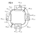
- FIG. 4 Another malfunction is shown as an example according to FIG. 4.
- a simple fault as shown in FIG. 3, there should also be a fault on the link WE CB .
- additional replacement switching protocols are exchanged.
- both the operating route and the replacement route are subject to faults. Due to the joint reservation of transmission capacity for alternative routes, if both operating routes concerned are switched to the respective alternative route, connections that are not influenced by the fault would also be affected. In the present case, these are the WT CD connections. Since switching in this case would be of no advantage, since the alternative route is also faulty, switching is therefore dispensed with in the event of double errors.
Applications Claiming Priority (2)
| Application Number | Priority Date | Filing Date | Title |
|---|---|---|---|
| DE19703992A DE19703992A1 (de) | 1997-02-03 | 1997-02-03 | Verfahren zum Ersatzschalten von Übertragungseinrichtungen in Ringarchitekturen zur bidirektionalen Übertragung von ATM-Zellen |
| DE19703992 | 1997-02-03 |
Publications (2)
| Publication Number | Publication Date |
|---|---|
| EP0857002A2 true EP0857002A2 (fr) | 1998-08-05 |
| EP0857002A3 EP0857002A3 (fr) | 1999-09-08 |
Family
ID=7819162
Family Applications (1)
| Application Number | Title | Priority Date | Filing Date |
|---|---|---|---|
| EP98101829A Withdrawn EP0857002A3 (fr) | 1997-02-03 | 1998-02-03 | Dispositif pour réaliser des circuits equivalents des dispositifs de communication dans des architectures d'anneau pour la transmission bidirectionelle des cellules ATM |
Country Status (5)
| Country | Link |
|---|---|
| US (1) | US6236640B1 (fr) |
| EP (1) | EP0857002A3 (fr) |
| JP (1) | JPH10257083A (fr) |
| CA (1) | CA2228482A1 (fr) |
| DE (1) | DE19703992A1 (fr) |
Cited By (2)
| Publication number | Priority date | Publication date | Assignee | Title |
|---|---|---|---|---|
| EP1130853A1 (fr) * | 2000-02-29 | 2001-09-05 | Siemens Aktiengesellschaft | Dispositif de circuit pour la commutation de substitution d' installations de transmission dans des architectures d' anneau avec des paquets de MPLS |
| EP1130852A1 (fr) * | 2000-02-29 | 2001-09-05 | Siemens Aktiengesellschaft | Procédé de commutation de substitution d' installations de transmission dans des architectures d' anneau avec des paquets de MPLS |
Families Citing this family (10)
| Publication number | Priority date | Publication date | Assignee | Title |
|---|---|---|---|---|
| WO2001020829A1 (fr) * | 1999-09-14 | 2001-03-22 | Megaxess, Inc. | Procede et appareil de prevention d'encombrements dans des reseaux atm au moyen de la commutation de protection atm |
| EP1126741A1 (fr) * | 2000-02-15 | 2001-08-22 | Siemens Aktiengesellschaft | Méthode de commutation de protection des dispositifs de transmission dans des réseaux MPLS |
| US6865149B1 (en) * | 2000-03-03 | 2005-03-08 | Luminous Networks, Inc. | Dynamically allocated ring protection and restoration technique |
| US7545755B2 (en) * | 2000-03-03 | 2009-06-09 | Adtran Inc. | Routing switch detecting change in session identifier before reconfiguring routing table |
| US20030031126A1 (en) * | 2001-03-12 | 2003-02-13 | Mayweather Derek T. | Bandwidth reservation reuse in dynamically allocated ring protection and restoration technique |
| US20030048501A1 (en) * | 2001-09-12 | 2003-03-13 | Michael Guess | Metropolitan area local access service system |
| US8611363B2 (en) * | 2002-05-06 | 2013-12-17 | Adtran, Inc. | Logical port system and method |
| US7421197B2 (en) * | 2003-01-21 | 2008-09-02 | Fujitsu Limited | Optical network protection switching architecture |
| EP1986772B1 (fr) * | 2006-02-14 | 2018-05-30 | Basf Se | Masse d'adsorption et procédé pour éliminer le co présent dans des flux de matière |
| DE102007017835A1 (de) * | 2007-04-16 | 2008-10-23 | Beckhoff Automation Gmbh | Paketvermittlungsvorrichtung und lokales Kommunikationsnetz mit einer solchen Paketvermittlungsvorrichtung |
Citations (2)
| Publication number | Priority date | Publication date | Assignee | Title |
|---|---|---|---|---|
| EP0538853A2 (fr) * | 1991-10-22 | 1993-04-28 | Fujitsu Limited | Commande distribuée d'un réseau de communication pour établir une voie de communication alternative |
| DE19544522A1 (de) * | 1994-12-27 | 1996-07-18 | Mitsubishi Electric Corp | ATM-Ringnetzsystem |
Family Cites Families (7)
| Publication number | Priority date | Publication date | Assignee | Title |
|---|---|---|---|---|
| EP0545932B1 (fr) * | 1990-08-31 | 1998-07-22 | Bell Communications Research, Inc. | Reseau maille autoreparateur utilisant des structures annulaires logiques |
| DE59205923D1 (de) * | 1991-01-23 | 1996-05-15 | Siemens Ag | Verfahren zur Ersatzschaltung eines Datenstroms |
| WO1994028646A1 (fr) * | 1993-05-28 | 1994-12-08 | Siemens Aktiengesellschaft | Procede permettant de realiser un circuit equivalent pour un dispositif de transmission destine a la transmission bidirectionnelle de signaux numeriques et configuration de mise en ×uvre dudit procede |
| DE4332824C1 (de) * | 1993-09-27 | 1995-03-16 | Siemens Ag | Verfahren und Schaltungsanordnung zum Übertragen von Nachrichtenzellen über virtuelle Pfade eines ATM-Kommunikationssystems |
| JPH08195756A (ja) * | 1994-11-15 | 1996-07-30 | Fujitsu Ltd | 二重化伝送装置の回線保護切替えシステム |
| US5621721A (en) * | 1995-01-12 | 1997-04-15 | Stratacom, Inc. | Maintaining database integrity throughout a communication network |
| CA2164071C (fr) * | 1995-09-06 | 2001-08-21 | Thomas P. J. Flanagan | Systeme de communication optique |
-
1997
- 1997-02-03 DE DE19703992A patent/DE19703992A1/de not_active Withdrawn
-
1998
- 1998-02-02 CA CA002228482A patent/CA2228482A1/fr not_active Abandoned
- 1998-02-02 JP JP10020782A patent/JPH10257083A/ja active Pending
- 1998-02-03 EP EP98101829A patent/EP0857002A3/fr not_active Withdrawn
- 1998-02-03 US US09/017,903 patent/US6236640B1/en not_active Expired - Fee Related
Patent Citations (2)
| Publication number | Priority date | Publication date | Assignee | Title |
|---|---|---|---|---|
| EP0538853A2 (fr) * | 1991-10-22 | 1993-04-28 | Fujitsu Limited | Commande distribuée d'un réseau de communication pour établir une voie de communication alternative |
| DE19544522A1 (de) * | 1994-12-27 | 1996-07-18 | Mitsubishi Electric Corp | ATM-Ringnetzsystem |
Non-Patent Citations (2)
| Title |
|---|
| MAY K P ET AL: "A FAST RESTORATION SYSTEM FOR ATM-RING-BASED LANS" IEEE COMMUNICATIONS MAGAZINE, Bd. 33, Nr. 9, 1. September 1995 (1995-09-01), Seiten 90-98, XP000528014 ISSN: 0163-6804 * |
| YOSHIO KAJIYAMA ET AL: "AN ATM VP-BASED SELF-HEALING RING" IEEE JOURNAL ON SELECTED AREAS IN COMMUNICATIONS, Bd. 12, Nr. 1, 1. Januar 1994 (1994-01-01), Seiten 171-177, XP000493898 ISSN: 0733-8716 * |
Cited By (8)
| Publication number | Priority date | Publication date | Assignee | Title |
|---|---|---|---|---|
| EP1130853A1 (fr) * | 2000-02-29 | 2001-09-05 | Siemens Aktiengesellschaft | Dispositif de circuit pour la commutation de substitution d' installations de transmission dans des architectures d' anneau avec des paquets de MPLS |
| EP1130852A1 (fr) * | 2000-02-29 | 2001-09-05 | Siemens Aktiengesellschaft | Procédé de commutation de substitution d' installations de transmission dans des architectures d' anneau avec des paquets de MPLS |
| WO2001065776A2 (fr) * | 2000-02-29 | 2001-09-07 | Siemens Aktiengesellschaft | Circuit pour commutation de remplacement de dispositifs de transmission dans des architectures en boucle utilisant les paquets a commutation par etiquette multiprotocole (mpls) |
| WO2001065775A1 (fr) * | 2000-02-29 | 2001-09-07 | Siemens Aktiengesellschaft | Procede de commutation de remplacement de dispositifs de transmission dans des architectures en boucle utilisant les paquets a commutation par etiquette multiprotocole (mpls) |
| WO2001065776A3 (fr) * | 2000-02-29 | 2002-01-31 | Siemens Ag | Circuit pour commutation de remplacement de dispositifs de transmission dans des architectures en boucle utilisant les paquets a commutation par etiquette multiprotocole (mpls) |
| US6704279B2 (en) * | 2000-02-29 | 2004-03-09 | Siemens Aktiengesellschaft | Circuit arrangement for providing a back-up circuit for transmission devices in ring architectures that route MPLS packets |
| AU2001250297B2 (en) * | 2000-02-29 | 2004-04-29 | Nokia Solutions And Networks Gmbh & Co. Kg | Circuit arrangement for providing a back-up circuit for transmission devices in ring architectures that route MPLS packets |
| CN1331334C (zh) * | 2000-02-29 | 2007-08-08 | 西门子公司 | 在对多协议分组标签交换-分组进行路由的环形结构中为传输设备提供备用电路的电路装置 |
Also Published As
| Publication number | Publication date |
|---|---|
| CA2228482A1 (fr) | 1998-08-03 |
| DE19703992A1 (de) | 1998-08-06 |
| JPH10257083A (ja) | 1998-09-25 |
| EP0857002A3 (fr) | 1999-09-08 |
| US6236640B1 (en) | 2001-05-22 |
Similar Documents
| Publication | Publication Date | Title |
|---|---|---|
| EP0937370B1 (fr) | Commutation sur circuit equivalent d'unites de transmission aux fins du transfert bidirectionnel de cellules en mode asynchrone | |
| EP0857002A2 (fr) | Dispositif pour réaliser des circuits equivalents des dispositifs de communication dans des architectures d'anneau pour la transmission bidirectionelle des cellules ATM | |
| DE3331446C2 (fr) | ||
| EP1130853A1 (fr) | Dispositif de circuit pour la commutation de substitution d' installations de transmission dans des architectures d' anneau avec des paquets de MPLS | |
| DE19737359C2 (de) | Kommunikationseinrichtung für die Übertragung von Nachrichtensignalen | |
| EP0448734B1 (fr) | Disposition de circuit pour tester par routine l'interface entre les groupes de transmission et le réseau de commutation d'un central de télécommunication à MIC | |
| EP1262084B1 (fr) | Procede de commutation de remplacement de dispositifs de transmission dans les reseaux mpls | |
| EP1410576B1 (fr) | Procede de commutation de remplacement de dispositifs de transmission dans des architectures en boucle utilisant les paquets a commutation par etiquette multiprotocole (mpls) | |
| EP1097540B1 (fr) | Procede et dispositif pour optimiser la securite de transmission et la tolerance aux defauts dans des reseaux de donnees a debit binaire eleve | |
| EP1425872B1 (fr) | Procédé et système de communication permettant d'établir au moins une liaison de communication à securité integrée | |
| WO1999014886A1 (fr) | Systeme de redondance '1:n' et '1:1' pour systeme asn | |
| EP0732828B1 (fr) | Réseau de communication optimisé en redondance pour la transmission de signaux de données | |
| DE19717584C2 (de) | Verfahren zum Ersatzschalten von Übertragungseinrichtungen zur bidirektionalen Übertragung von ATM-Zellen | |
| EP0857003A2 (fr) | Dispositif pour réaliser des circutis equivalents des dispositifs de communication dans des architectures d'anneau pour la transmission bidirectionelle des cellules ATM | |
| WO2000030300A1 (fr) | Procede permettant l'extension sans interruption du reseau de connexion d'un systeme de communication | |
| EP1126741A1 (fr) | Méthode de commutation de protection des dispositifs de transmission dans des réseaux MPLS | |
| DE19856835C2 (de) | Verfahren zum Betreiben von Peripheriebaugruppen innerhalb einer ATM-Kommunikationseinrichtung | |
| DE10152339B4 (de) | Verfahren und Kommunikationseinrichtung zur Realisierung zumindest einer ausfallsicheren Kommunikationsbeziehung durch eine in einem Kommunikationsnetz angeordnete Kommunikationseinrichtung | |
| EP0539761B1 (fr) | Procédé et système pour détecter un canal défectueux entre un groupe de canaux | |
| WO2000019766A1 (fr) | Circuit et procede pour interconnecter les canaux d'une connexion a canaux multiples | |
| EP0876068A1 (fr) | Concentrateur pour la connection des abonnés |
Legal Events
| Date | Code | Title | Description |
|---|---|---|---|
| PUAI | Public reference made under article 153(3) epc to a published international application that has entered the european phase |
Free format text: ORIGINAL CODE: 0009012 |
|
| AK | Designated contracting states |
Kind code of ref document: A2 Designated state(s): BE DE ES FR GB IT |
|
| AX | Request for extension of the european patent |
Free format text: AL;LT;LV;MK;RO;SI |
|
| PUAL | Search report despatched |
Free format text: ORIGINAL CODE: 0009013 |
|
| AK | Designated contracting states |
Kind code of ref document: A3 Designated state(s): AT BE CH DE DK ES FI FR GB GR IE IT LI LU MC NL PT SE |
|
| AX | Request for extension of the european patent |
Free format text: AL;LT;LV;MK;RO;SI |
|
| RIC1 | Information provided on ipc code assigned before grant |
Free format text: 6H 04Q 11/04 A, 6H 04L 12/56 B |
|
| 17P | Request for examination filed |
Effective date: 19991005 |
|
| AKX | Designation fees paid |
Free format text: BE DE ES FR GB IT |
|
| STAA | Information on the status of an ep patent application or granted ep patent |
Free format text: STATUS: THE APPLICATION IS DEEMED TO BE WITHDRAWN |
|
| 18D | Application deemed to be withdrawn |
Effective date: 20030902 |