EP1424749A2 - System zur elektrischen Kontaktierung mit einem Leiter, insbesondere für eine Heizungs-oder Klimaanlage für ein Kraftfahrzeug - Google Patents
System zur elektrischen Kontaktierung mit einem Leiter, insbesondere für eine Heizungs-oder Klimaanlage für ein Kraftfahrzeug Download PDFInfo
- Publication number
- EP1424749A2 EP1424749A2 EP03024152A EP03024152A EP1424749A2 EP 1424749 A2 EP1424749 A2 EP 1424749A2 EP 03024152 A EP03024152 A EP 03024152A EP 03024152 A EP03024152 A EP 03024152A EP 1424749 A2 EP1424749 A2 EP 1424749A2
- Authority
- EP
- European Patent Office
- Prior art keywords
- contact
- conductor
- electrical
- component
- housing
- Prior art date
- Legal status (The legal status is an assumption and is not a legal conclusion. Google has not performed a legal analysis and makes no representation as to the accuracy of the status listed.)
- Withdrawn
Links
Images



Classifications
-
- H—ELECTRICITY
- H01—ELECTRIC ELEMENTS
- H01R—ELECTRICALLY-CONDUCTIVE CONNECTIONS; STRUCTURAL ASSOCIATIONS OF A PLURALITY OF MUTUALLY-INSULATED ELECTRICAL CONNECTING ELEMENTS; COUPLING DEVICES; CURRENT COLLECTORS
- H01R12/00—Structural associations of a plurality of mutually-insulated electrical connecting elements, specially adapted for printed circuits, e.g. printed circuit boards [PCB], flat or ribbon cables, or like generally planar structures, e.g. terminal strips, terminal blocks; Coupling devices specially adapted for printed circuits, flat or ribbon cables, or like generally planar structures; Terminals specially adapted for contact with, or insertion into, printed circuits, flat or ribbon cables, or like generally planar structures
- H01R12/50—Fixed connections
- H01R12/59—Fixed connections for flexible printed circuits, flat or ribbon cables or like structures
- H01R12/62—Fixed connections for flexible printed circuits, flat or ribbon cables or like structures connecting to rigid printed circuits or like structures
-
- H—ELECTRICITY
- H01—ELECTRIC ELEMENTS
- H01R—ELECTRICALLY-CONDUCTIVE CONNECTIONS; STRUCTURAL ASSOCIATIONS OF A PLURALITY OF MUTUALLY-INSULATED ELECTRICAL CONNECTING ELEMENTS; COUPLING DEVICES; CURRENT COLLECTORS
- H01R12/00—Structural associations of a plurality of mutually-insulated electrical connecting elements, specially adapted for printed circuits, e.g. printed circuit boards [PCB], flat or ribbon cables, or like generally planar structures, e.g. terminal strips, terminal blocks; Coupling devices specially adapted for printed circuits, flat or ribbon cables, or like generally planar structures; Terminals specially adapted for contact with, or insertion into, printed circuits, flat or ribbon cables, or like generally planar structures
- H01R12/50—Fixed connections
- H01R12/59—Fixed connections for flexible printed circuits, flat or ribbon cables or like structures
- H01R12/65—Fixed connections for flexible printed circuits, flat or ribbon cables or like structures characterised by the terminal
- H01R12/67—Fixed connections for flexible printed circuits, flat or ribbon cables or like structures characterised by the terminal insulation penetrating terminals
- H01R12/68—Fixed connections for flexible printed circuits, flat or ribbon cables or like structures characterised by the terminal insulation penetrating terminals comprising deformable portions
-
- H—ELECTRICITY
- H01—ELECTRIC ELEMENTS
- H01R—ELECTRICALLY-CONDUCTIVE CONNECTIONS; STRUCTURAL ASSOCIATIONS OF A PLURALITY OF MUTUALLY-INSULATED ELECTRICAL CONNECTING ELEMENTS; COUPLING DEVICES; CURRENT COLLECTORS
- H01R12/00—Structural associations of a plurality of mutually-insulated electrical connecting elements, specially adapted for printed circuits, e.g. printed circuit boards [PCB], flat or ribbon cables, or like generally planar structures, e.g. terminal strips, terminal blocks; Coupling devices specially adapted for printed circuits, flat or ribbon cables, or like generally planar structures; Terminals specially adapted for contact with, or insertion into, printed circuits, flat or ribbon cables, or like generally planar structures
- H01R12/70—Coupling devices
- H01R12/7005—Guiding, mounting, polarizing or locking means; Extractors
- H01R12/7011—Locking or fixing a connector to a PCB
-
- H—ELECTRICITY
- H01—ELECTRIC ELEMENTS
- H01R—ELECTRICALLY-CONDUCTIVE CONNECTIONS; STRUCTURAL ASSOCIATIONS OF A PLURALITY OF MUTUALLY-INSULATED ELECTRICAL CONNECTING ELEMENTS; COUPLING DEVICES; CURRENT COLLECTORS
- H01R13/00—Details of coupling devices of the kinds covered by groups H01R12/70 or H01R24/00 - H01R33/00
- H01R13/02—Contact members
- H01R13/22—Contacts for co-operating by abutting
- H01R13/24—Contacts for co-operating by abutting resilient; resiliently-mounted
- H01R13/2407—Contacts for co-operating by abutting resilient; resiliently-mounted characterized by the resilient means
- H01R13/2414—Contacts for co-operating by abutting resilient; resiliently-mounted characterized by the resilient means conductive elastomers
-
- H—ELECTRICITY
- H01—ELECTRIC ELEMENTS
- H01R—ELECTRICALLY-CONDUCTIVE CONNECTIONS; STRUCTURAL ASSOCIATIONS OF A PLURALITY OF MUTUALLY-INSULATED ELECTRICAL CONNECTING ELEMENTS; COUPLING DEVICES; CURRENT COLLECTORS
- H01R13/00—Details of coupling devices of the kinds covered by groups H01R12/70 or H01R24/00 - H01R33/00
- H01R13/02—Contact members
- H01R13/22—Contacts for co-operating by abutting
- H01R13/24—Contacts for co-operating by abutting resilient; resiliently-mounted
- H01R13/2442—Contacts for co-operating by abutting resilient; resiliently-mounted with a single cantilevered beam
-
- H—ELECTRICITY
- H05—ELECTRIC TECHNIQUES NOT OTHERWISE PROVIDED FOR
- H05K—PRINTED CIRCUITS; CASINGS OR CONSTRUCTIONAL DETAILS OF ELECTRIC APPARATUS; MANUFACTURE OF ASSEMBLAGES OF ELECTRICAL COMPONENTS
- H05K3/00—Apparatus or processes for manufacturing printed circuits
- H05K3/30—Assembling printed circuits with electric components, e.g. with resistors
- H05K3/32—Assembling printed circuits with electric components, e.g. with resistors electrically connecting electric components or wires to printed circuits
- H05K3/325—Assembling printed circuits with electric components, e.g. with resistors electrically connecting electric components or wires to printed circuits by abutting or pinching; Mechanical auxiliary parts therefor
Definitions
- the invention relates to a system for electrical contacting with a Ladder, in particular for a heating or air conditioning system for a motor vehicle.
- Today's vehicle air conditioning systems are controlled by a control unit or regulated as a structural unit with a control panel in the center console or is arranged in the dashboard, is formed.
- the operating and control unit has controls, such as switches, buttons, knobs etc., on, over the user settings, such as desired temperature, desired Air distribution, etc., are entered.
- the entered signals be electronically processed in the control unit and via electrical Connections, usually round conductors, the air conditioner, the air duct housing with filters arranged therein, heat exchangers, air flow control elements, Actuators and possibly sensors includes supplied.
- electrical Connections usually round conductors, the air conditioner, the air duct housing with filters arranged therein, heat exchangers, air flow control elements, Actuators and possibly sensors includes supplied.
- Via a wiring harness are the electrical components of the air conditioner, such as sensors and actuators, such as stepper motors for the Air flow control elements and the fan, electrically connected to each other.
- From DE 196 05 999 A1 is a contacting of a planar antenna conductor structure known, which in a vehicle component, in particular a Vehicle window, integrated.
- first contacting means which are arranged on the vehicle body part
- second contacting means which on the body side on at least one Contact foot are arranged provided.
- the contacting of the first Contacting means with the corresponding second contacting means takes place by a relative movement between vehicle component and Contact foot during installation, the relative movement on the one hand already built-contact foot through the vehicle component, for example by Put on, on the other hand with already installed vehicle component by the contact foot, for example by plugging, is executed.
- contacting leaves something to be desired.
- a housing for electrical connection of an electrical component, for example a blower or control electronics, directly during assembly a housing, in particular of a heating or air conditioning for a Motor vehicle, preferably on an air guide housing, are contact surfaces on the electrical component, hereinafter also referred to as Component is referred to, and the corresponding electrical conductor, for example, a round conductor or an FPC (flexible printed circuit), which is connected to the housing, provided, wherein the contacts are defined so that simultaneously with the assembly, i. with the Positioning of the corresponding component and its fixation, the electrical Contact is made without additional handles.
- the direct contact are not three contact points, namely from conductor to connector, from Plug to socket and from socket to the second conductor, required.
- At least one of the two Contact surfaces of the contact point which is closed during assembly, elastic.
- the contacting takes place during assembly, in particular from above, obliquely and / or laterally with respect to the housing surface in the contacting region.
- At least one positioning and / or fastening element is on the housing provided for easy positioning of the component is possible on the housing and the attachment can be done quickly, so that the assembly is simplified and the production costs are reduced.
- the contact surface by a projection, a snap disk, a spring clip, a socket contact or an insulation displacement contact educated.
- the electrical conductor is a partial flattened round conductor or around a flat conductor, e.g. FPC or FFC (flexible flat cable).
- a flat conductor e.g. FPC or FFC (flexible flat cable).
- one of the two conductors runs in the region of the contact surface thereof not really. This can be done, for example, by attaching a elastic material can be effected under the conductor, leaving the conductor the contact point is bent.
- the component has a board on which the contact-forming Element is attached directly.
- the electronics can also work on one MID component, i. a spatially injection-molded circuit carrier with integrated Ladder picture structure, be attached.
- the attachment to a stamped grid in which case preferably the leadframe in a Plastic housing is injected and the contact surfaces on the components are soldered and exposed.
- the use of an FPC as Circuit board possible, especially if the component carrier, i. the FPC and that Contact element to the conductor is made in one piece.
- the component or the housing an elastic material, preferably an elastomer, provided which forms a projection over which one of the conductors to form the corresponding Contact surface is guided.
- a particularly quick and easy attachment of the component to the housing is possible by means of a clip connection, wherein the electrical contact just before or at the latest with closing, i. the snap, the clip connection he follows.
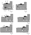
- Fig. 1 shows a housing 1 of an air conditioner for a motor vehicle, on which an electrical conductor 2, according to the first embodiment, a flat conductor 3, in this case an FPC, is fixed.
- the conductor 2 is designed such in that it has an electrical contact area in a predetermined area 4 5, at which an electrical contact with a second conductor 2 ', in the present case also a flat conductor 3 'in the form of an FPC is formed (Contact point).
- the flat conductor 3 ' is part of a component, which is also can act to an assembly which is attached to the housing 1.
- the Component around a Shaverstellmotor with its associated electronics In this case, the flat conductor 3 'is soldered to the board of the electronics.
- electrical component 6 is applied to the unit flat conductor 3 ', electronics and other Component referred to as electrical component 6 reference. Because the flat conductor 3 'is part of the component, there is only one contact point.
- the housing 1 two positioning and fastening elements. 7 provided, shown in Fig. 1 at the top of the housing 1, with the help of the electrical component 6 positioned and at or by means of which the same is fixed.
- the area is 4 arranged on the same side as the fasteners 7.
- the electrical component 6 with the help of the two Fastening elements 7 positioned, whereby shortly before reaching the end position also the two electrical contact surfaces 5 and 5 'together Come in contact.
- a deformation takes place of the elastic material 8 until the end position is reached.
- the deformation is essentially an elastic one Deformation, so that the electrical component 6 later easily can be exchanged.
- the second exemplary embodiment illustrated in FIG. 2 is essentially correct, i.e. In terms of the type of contacting, with the first embodiment match, but the contact is made perpendicular to the assembly direction.
- third embodiment is correct with respect to the contacting direction substantially with the first embodiment
- the contact is made by a directly with the board formed from below connected snap-action disc 30, instead of using the elastic material 8.
- the snap-action disc 30 simultaneously forms the second conductor 32 '.
- the housing 31 is formed such that the first conductor 32 is positioned just below the board, leaving a direct Contacting is possible.
- two contact points exist, namely one between the first conductor 32 and Snap disk 30 and the second between snap disk 30 and board.
- fourth embodiment is essentially true with the third embodiment, but is done accordingly the second embodiment, the contact perpendicular to Assembly direction, to which the board is designed accordingly, i. E. L-shaped.
- the fifth embodiment shown in Fig. 5 is correct with respect to the contacting direction substantially with the third embodiment However, instead of the bottom of the board is arranged Snap-action disc 30 a arranged from the top of the board spring clip 50 provided.
- the sixth embodiment shown in Fig. 6 is correct with respect to the kind of contacting substantially with the fifth embodiment match, but takes place, according to the fourth embodiment, the Contact perpendicular to the assembly direction, including the board accordingly the fourth embodiment is configured.
- the seventh embodiment shown in Fig. 7 is correct in view the contacting direction substantially with that shown in Fig. 5 fifth embodiment, but instead of the spring clip 50th a socket contact 70 is provided. Furthermore, the housing 71 is corresponding formed in the first embodiment, wherein it is in the area 74 a web 74a over which the first conductor 72 is guided, and about the bushing contact 70 by means of two contact surfaces 75 ', through resilient elements are formed, the electrical contact forms.
- the eighth embodiment shown in Fig. 8 is correct in view the type of contacting substantially with the seventh shown in Fig. 7 and with respect to the contacting direction with that shown in Fig. 6 sixth embodiment, but the assembly takes place in the direction of Fig. 8, and not, as in the sixth embodiment from above.
- the ninth embodiment shown in Fig. 9 is correct in view the contacting direction substantially with that shown in Fig. 7 eighth embodiment, but is used as an electrical conductor 92 instead of the flat conductor 3 a round conductor 93a fixed to the housing 91, which contacted by a cutting terminal contact 90. Scraping or the insulation displacement contact 90 presses into the circular conductor 93a.
- the tenth embodiment shown in Fig. 10 is correct in view the type of contacting substantially with the ninth shown in Fig. 9 as well as with respect to the contacting direction substantially the in Fig. 8 illustrated eighth embodiment match.
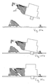
- FIG. 11c shows an eleventh exemplary embodiment, which is essentially corresponds to the fifth embodiment.
- the Contacting with the help of a spring clip 100 on a slope is the component inserted with a projection in a receptacle (Fig. 11 b) and a through this recording extending axis pivots to a clip connection snaps (Fig. 11c) and a secure connection between the component and housing guaranteed.
- the electrical contact takes place shortly before Termination of the pivoting movement, wherein the spring clip 100 slightly elastic is deformed.
- Fig. 14 are various preferred shapes for the contact surfaces
- the elastomer according to the first and second embodiment have a corresponding shape.
Landscapes
- Coupling Device And Connection With Printed Circuit (AREA)
- Air-Conditioning For Vehicles (AREA)
Abstract
Description
- Fig. 1
- einen Schnitt durch ein erstes Ausführungsbeispiel;
- Fig. 2
- einen Schnitt durch ein zweites Ausführungsbeispiel;
- Fig. 3
- einen Schnitt durch ein drittes Ausführungsbeispiel;
- Fig. 4
- einen Schnitt durch ein viertes Ausführungsbeispiel;
- Fig. 5
- einen Schnitt durch ein fünftes Ausführungsbeispiel;
- Fig. 6
- einen Schnitt durch ein sechstes Ausführungsbeispiel;
- Fig. 7
- einen Schnitt durch ein siebtes Ausführungsbeispiel;
- Fig. 8
- einen Schnitt durch ein achtes Ausführungsbeispiel;
- Fig. 9
- einen Schnitt durch ein neuntes Ausführungsbeispiel;
- Fig. 10
- einen Schnitt durch ein zehntes Ausführungsbeispiel;
- Fig. 11a-c
- einen Schnitt durch ein elftes Ausführungsbeispiel in verschiedenen Schritten beim Zusammenbau;
- Fig. 12
- eine Draufsicht auf das elfte Ausführungsbeispiel ohne Bauteil;
- Fig. 13
- eine Draufsicht auf das elfte Ausführungsbeispiel mit Bauteil; und
- Fig. 14
- beispielhaft verschiedene Formen möglicher Kontaktflächen.
Claims (17)
- System zur elektrischen Kontaktierung eines elektrischen Bauteils (6), insbesondere für eine Heizungs- oder Klimaanlage für ein Kraftfahrzeug, mit Kontaktflächen zur Herstellung eines elektrischen Kontaktes zwischen dem elektrischen Bauteil (6) und einem elektrischen Leiter (2; 32; 72; 92), der an einem Gehäuse (1; 71; 91) angeordnet ist, wobei zwischen elektrischem Bauteil (6) und dem Leiter (2; 32; 72; 92) maximal zwei Kontaktstellen vorgesehen sind.
- System nach Anspruch 1, dadurch gekennzeichnet, dass mindestens eine der beiden Kontaktflächen wenigstens einer Kontaktstelle elastisch ausgebildet ist.
- System nach Anspruch 1 oder 2, dadurch gekennzeichnet, dass direkt am elektrischen Bauteil (6) oder über eine einzige elektrische Kontaktstelle verbunden mit dem elektrischen Bauteil (6) ein Bereich (4') mit einer elektrischen Kontaktfläche (5') vorgesehen ist, der direkt den am Gehäuse (1; 71; 91) angeordneten Leiter (2; 32; 72; 92) an einer Kontaktfläche (5) kontaktiert.
- System nach einem der vorstehenden Ansprüche, dadurch gekennzeichnet, dass die Kontaktfläche des am Gehäuse (1; 71; 91) angeordneten Leiters (2; 32; 72; 92) oben, schräg und/oder seitlich bezogen auf die Gehäuseoberfläche im Kontaktierungsbereich vorgesehen ist.
- System nach einem der vorstehenden Ansprüche, dadurch gekennzeichnet, dass am Gehäuse (1; 71; 91) mindestens ein Positionierund/oder Befestigungselement (7) vorgesehen ist.
- System nach einem der vorstehenden Ansprüche, dadurch gekennzeichnet, dass die Kontaktfläche (5'; 75') durch einen Vorsprung (10), eine Schnappscheibe (30), einen Federbügel (50; 100), einen Buchsenkontakt (70) oder einen Schneidklemmkontakt (90) gebildet ist.
- System nach einem der vorstehenden Ansprüche, dadurch gekennzeichnet, dass die Kontaktfläche (5) durch einen Flachleiter (3) oder einen Rundleiter (93a) gebildet ist.
- System nach Anspruch 7, dadurch gekennzeichnet, dass der Leiter im Bereich der Kontaktfläche (5) nicht gerade verläuft.
- System nach einem der vorstehenden Ansprüche, dadurch gekennzeichnet, dass das Bauteil (6) eine Platine, ein MID Bauteil mit hieran angebrachter Elektronik, ein Stanzgitter oder eine FPC aufweist.
- System nach Anspruch 9, dadurch gekennzeichnet, dass an der Platine ein Leiter (2') kontaktiert ist, der mit dem Leiter (2) den elektrischen Kontakt direkt bildet.
- System nach Anspruch 10, dadurch gekennzeichnet, dass ein elastisches Material (8) vorgesehen ist, welches einen Vorsprung (10) bildet, über welchen einer der Leiter (2; 2') zur Bildung der entsprechenden Kontaktfläche (5; 5') geführt ist.
- System nach Anspruch 11, dadurch gekennzeichnet, dass das elastische Material (8) ein Elastomer (9) ist.
- System nach einem der vorstehenden Ansprüche, dadurch gekennzeichnet, dass die kontaktbildenden Elemente (10; 30; 50; 70; 90) direkt an der Platine kontaktiert sind.
- System nach Anspruch 13, dadurch gekennzeichnet, dass die kontaktbildenden Elemente (30; 50; 70; 90; 100) direkt an der Platine befestigt sind.
- System nach einem der vorstehenden Ansprüche, dadurch gekennzeichnet, dass das Bauteil ( 6) auswechselbar ist.
- System nach einem der vorstehenden Ansprüchen, dadurch gekennzeichnet, dass das Bauteil mittels einer Clipsverbindung am Gehäuse befestigt ist.
- System nach Anspruch 16, dadurch gekennzeichnet, dass die Clipsverbindung ein Elastomer ist.
Applications Claiming Priority (2)
| Application Number | Priority Date | Filing Date | Title |
|---|---|---|---|
| DE10256104 | 2002-11-29 | ||
| DE2002156104 DE10256104A1 (de) | 2002-11-29 | 2002-11-29 | System zur elektrischen Kontaktierung mit einem Leiter, insbesondere für eine Heizungs- oder Klimaanlage für ein Kraftfahrzeug |
Publications (2)
| Publication Number | Publication Date |
|---|---|
| EP1424749A2 true EP1424749A2 (de) | 2004-06-02 |
| EP1424749A3 EP1424749A3 (de) | 2007-10-10 |
Family
ID=32240550
Family Applications (1)
| Application Number | Title | Priority Date | Filing Date |
|---|---|---|---|
| EP03024152A Withdrawn EP1424749A3 (de) | 2002-11-29 | 2003-10-20 | System zur elektrischen Kontaktierung mit einem Leiter, insbesondere für eine Heizungs-oder Klimaanlage für ein Kraftfahrzeug |
Country Status (2)
| Country | Link |
|---|---|
| EP (1) | EP1424749A3 (de) |
| DE (1) | DE10256104A1 (de) |
Cited By (3)
| Publication number | Priority date | Publication date | Assignee | Title |
|---|---|---|---|---|
| WO2008049709A1 (de) * | 2006-10-24 | 2008-05-02 | Robert Bosch Gmbh | Verbindung eines bauteils mit einem trägerteil |
| WO2013045222A1 (de) * | 2011-09-26 | 2013-04-04 | Siemens Aktiengesellschaft | Kontaktfederanordnung und verfahren zur herstellung derselben |
| CN116171488A (zh) * | 2020-08-07 | 2023-05-26 | 西门子股份公司 | 具有可靠绝缘的接触系统 |
Families Citing this family (2)
| Publication number | Priority date | Publication date | Assignee | Title |
|---|---|---|---|---|
| DE102006062485A1 (de) * | 2006-12-28 | 2008-07-03 | Robert Bosch Gmbh | Elektrische Kontaktiervorrichtung, insbesondere für elektronische Schaltungen, und elektrische/elektronische Schaltung |
| DE102023208623A1 (de) | 2023-09-06 | 2025-03-06 | Robert Bosch Gesellschaft mit beschränkter Haftung | Kontaktanordnung und Verfahren zur Ausbildung einer Kontaktanordnung |
Family Cites Families (17)
| Publication number | Priority date | Publication date | Assignee | Title |
|---|---|---|---|---|
| JPS59145B2 (ja) * | 1978-06-02 | 1984-01-05 | 日産自動車株式会社 | 自動車用電気機器の通電構造 |
| US4784615A (en) * | 1987-01-07 | 1988-11-15 | Motorola, Inc. | Direct contact flexible circuit interconnect system and method |
| DE4416096A1 (de) * | 1994-04-19 | 1995-10-26 | Deutsche Telephonwerk Kabel | Kontaktierung von Betätigungs- und Anzeigemitteln |
| DE9417135U1 (de) * | 1994-10-25 | 1994-12-15 | Siemens AG, 80333 München | Baugruppe |
| DE29519209U1 (de) * | 1995-12-04 | 1996-03-07 | Siemens AG, 80333 München | Batteriefach zur Aufnahme von Batteriezellen |
| DE19605999C2 (de) * | 1996-02-17 | 1999-10-14 | Daimler Chrysler Ag | Kontaktierung einer flächigen Antennenleiterstruktur |
| JP3144468B2 (ja) * | 1996-05-16 | 2001-03-12 | 矢崎総業株式会社 | インパネ用ワイヤハーネス装置 |
| US5813876A (en) * | 1996-06-13 | 1998-09-29 | Intel Corporation | Pressure actuated zero insertion force circuit board edge connector socket |
| JPH1029475A (ja) * | 1996-07-15 | 1998-02-03 | Yazaki Corp | インストルメントパネルユニット |
| DE29617455U1 (de) * | 1996-09-27 | 1997-08-28 | Siemens AG, 80333 München | Anschlußleitung für eine Endeinrichtung eines mit einer Multiplexsteuerung versehenen Bordnetzes eines Kraftfahrzeuges |
| DE19724664B4 (de) * | 1997-06-11 | 2008-01-03 | Lisa Dräxlmaier GmbH | Einbauteil mit speziellem elektrischen Kontaktierungssystem |
| DE29823576U1 (de) * | 1998-07-16 | 1999-09-02 | Leopold Kostal GmbH & Co KG, 58507 Lüdenscheid | Flexible Leiterfolie mit einem zum lösbaren Verbinden vorgesehenen Anschlußbereich für elektrische Leiterplatten |
| FR2784260B1 (fr) * | 1998-10-01 | 2000-12-22 | Valeo Electronique | Contacts sans soudure entre des pistes decoupees et un circuit imprime |
| US6585538B2 (en) * | 1999-04-22 | 2003-07-01 | Visteon Global Technologies, Inc. | Continuous conductor connector system for printed circuit boards |
| DE10039576A1 (de) * | 2000-08-12 | 2002-02-21 | Behr Gmbh & Co | Heizungs- oder Klimaanlage für ein Kraftfahrzeug |
| DE20113304U1 (de) * | 2001-08-10 | 2001-12-20 | ArvinMeritor GmbH, 63128 Dietzenbach | Fahrzeuginnenraummodul |
| DE10202379A1 (de) * | 2002-01-23 | 2003-08-07 | Conti Temic Microelectronic | Elektronische Baugruppe |
-
2002
- 2002-11-29 DE DE2002156104 patent/DE10256104A1/de not_active Ceased
-
2003
- 2003-10-20 EP EP03024152A patent/EP1424749A3/de not_active Withdrawn
Cited By (3)
| Publication number | Priority date | Publication date | Assignee | Title |
|---|---|---|---|---|
| WO2008049709A1 (de) * | 2006-10-24 | 2008-05-02 | Robert Bosch Gmbh | Verbindung eines bauteils mit einem trägerteil |
| WO2013045222A1 (de) * | 2011-09-26 | 2013-04-04 | Siemens Aktiengesellschaft | Kontaktfederanordnung und verfahren zur herstellung derselben |
| CN116171488A (zh) * | 2020-08-07 | 2023-05-26 | 西门子股份公司 | 具有可靠绝缘的接触系统 |
Also Published As
| Publication number | Publication date |
|---|---|
| EP1424749A3 (de) | 2007-10-10 |
| DE10256104A1 (de) | 2004-06-24 |
Similar Documents
| Publication | Publication Date | Title |
|---|---|---|
| EP2219911B1 (de) | Anschlusselement und zugehörige fluidbaugruppe | |
| DE102016205476B4 (de) | Steckeraufnahme und Stecker für eine elektrische Steckverbindung und elektrische Steckverbindung | |
| DE102010060252B4 (de) | Elektrische Anschlussbaueinheit | |
| DE19654637A1 (de) | Anordnung und Verfahren zur Montage einer Einheit mit einer elektrischen Vorrichtung | |
| DE60312100T2 (de) | Kabelbaum | |
| EP1728414B1 (de) | Anordnung mit einem elektromotor und einer hauptleiterplatte und montageverfahren | |
| DE19832011A1 (de) | Flachbandleitung mit einem zum lösbaren Verbinden vorgesehenen Anschlußbereich | |
| EP3850320A1 (de) | Vorrichtung zum messen der temperatur in dem innenraum eines fahrzeugs | |
| DE10249683B4 (de) | Kontaktklemme zur elektr. Kontaktierung eines Gegenkontaktes, insb. für den Einsatz bei elektrischen Kraftfahrzeugkomponenten, wie bspw. Fensterhebersystemen o. dgl. | |
| EP0699017A2 (de) | Elektrisches oder elektronisches Gerät für ein Kraftfahrzeug | |
| DE10256104A1 (de) | System zur elektrischen Kontaktierung mit einem Leiter, insbesondere für eine Heizungs- oder Klimaanlage für ein Kraftfahrzeug | |
| DE10033088B4 (de) | Aufschnappen des Spiegelantriebes | |
| EP1683238B1 (de) | Steckverbinder zur elektrischen Kontaktierung von Verbrauchern | |
| DE10107630B4 (de) | Stiftleiste und Sensorsystem für Kraftfahrzeuge mit derartiger Stiftleiste | |
| EP3738175A1 (de) | Steckverbinderanordnung | |
| DE102016107898B4 (de) | Laterale Leiterplattenverbindung | |
| DE602004008094T2 (de) | Elektrischer verbinder für einen flexiblen flachleiter und schalteinrichtung | |
| EP3300180A1 (de) | Verbesserte mehrfach-direktkontaktierung von elektrischen bauteilen | |
| DE102015100912B4 (de) | Leiterplatten-Verbinderanordnung und Leiterplattenverbinder hierzu | |
| EP3679629A1 (de) | Kontaktelement, steckeranschlusseinheit und steuergerät | |
| EP3700018B1 (de) | Leiterplattendirektkontaktierungsvorrichtung zum herstellen eines elektrischen kontakts sowie leiterplatte und elektrisches gerät | |
| EP0972682B1 (de) | Zentralelektrik | |
| DE102005005705A1 (de) | Kontaktierungsmittel für flexible elektrische Flachbandkabel | |
| DE102004023189A1 (de) | Lösbare elektrische Kontaktierung dreidimensionaler spritzgegossener Schaltungsträger | |
| DE7614112U1 (de) | Steckvorrichtung zum Anschließen elektrischer Bauteile mit Flachstiften |
Legal Events
| Date | Code | Title | Description |
|---|---|---|---|
| PUAI | Public reference made under article 153(3) epc to a published international application that has entered the european phase |
Free format text: ORIGINAL CODE: 0009012 |
|
| AK | Designated contracting states |
Kind code of ref document: A2 Designated state(s): AT BE BG CH CY CZ DE DK EE ES FI FR GB GR HU IE IT LI LU MC NL PT RO SE SI SK TR |
|
| AX | Request for extension of the european patent |
Extension state: AL LT LV MK |
|
| PUAL | Search report despatched |
Free format text: ORIGINAL CODE: 0009013 |
|
| AK | Designated contracting states |
Kind code of ref document: A3 Designated state(s): AT BE BG CH CY CZ DE DK EE ES FI FR GB GR HU IE IT LI LU MC NL PT RO SE SI SK TR |
|
| AX | Request for extension of the european patent |
Extension state: AL LT LV MK |
|
| AKX | Designation fees paid | ||
| STAA | Information on the status of an ep patent application or granted ep patent |
Free format text: STATUS: THE APPLICATION IS DEEMED TO BE WITHDRAWN |
|
| 18D | Application deemed to be withdrawn |
Effective date: 20080411 |
|
| REG | Reference to a national code |
Ref country code: DE Ref legal event code: 8566 |