EP1424293A2 - Plastic packaging container - Google Patents
Plastic packaging container Download PDFInfo
- Publication number
- EP1424293A2 EP1424293A2 EP03027250A EP03027250A EP1424293A2 EP 1424293 A2 EP1424293 A2 EP 1424293A2 EP 03027250 A EP03027250 A EP 03027250A EP 03027250 A EP03027250 A EP 03027250A EP 1424293 A2 EP1424293 A2 EP 1424293A2
- Authority
- EP
- European Patent Office
- Prior art keywords
- flat
- packaging container
- film
- flat tube
- container according
- Prior art date
- Legal status (The legal status is an assumption and is not a legal conclusion. Google has not performed a legal analysis and makes no representation as to the accuracy of the status listed.)
- Granted
Links
Images

Classifications
-
- B—PERFORMING OPERATIONS; TRANSPORTING
- B65—CONVEYING; PACKING; STORING; HANDLING THIN OR FILAMENTARY MATERIAL
- B65D—CONTAINERS FOR STORAGE OR TRANSPORT OF ARTICLES OR MATERIALS, e.g. BAGS, BARRELS, BOTTLES, BOXES, CANS, CARTONS, CRATES, DRUMS, JARS, TANKS, HOPPERS, FORWARDING CONTAINERS; ACCESSORIES, CLOSURES, OR FITTINGS THEREFOR; PACKAGING ELEMENTS; PACKAGES
- B65D81/00—Containers, packaging elements, or packages, for contents presenting particular transport or storage problems, or adapted to be used for non-packaging purposes after removal of contents
- B65D81/24—Adaptations for preventing deterioration or decay of contents; Applications to the container or packaging material of food preservatives, fungicides, pesticides or animal repellants
- B65D81/26—Adaptations for preventing deterioration or decay of contents; Applications to the container or packaging material of food preservatives, fungicides, pesticides or animal repellants with provision for draining away, or absorbing, or removing by ventilation, fluids, e.g. exuded by contents; Applications of corrosion inhibitors or desiccators
- B65D81/266—Adaptations for preventing deterioration or decay of contents; Applications to the container or packaging material of food preservatives, fungicides, pesticides or animal repellants with provision for draining away, or absorbing, or removing by ventilation, fluids, e.g. exuded by contents; Applications of corrosion inhibitors or desiccators for absorbing gases, e.g. oxygen absorbers or desiccants
-
- B—PERFORMING OPERATIONS; TRANSPORTING
- B31—MAKING ARTICLES OF PAPER, CARDBOARD OR MATERIAL WORKED IN A MANNER ANALOGOUS TO PAPER; WORKING PAPER, CARDBOARD OR MATERIAL WORKED IN A MANNER ANALOGOUS TO PAPER
- B31B—MAKING CONTAINERS OF PAPER, CARDBOARD OR MATERIAL WORKED IN A MANNER ANALOGOUS TO PAPER
- B31B70/00—Making flexible containers, e.g. envelopes or bags
- B31B70/008—Stiffening or reinforcing
-
- B—PERFORMING OPERATIONS; TRANSPORTING
- B65—CONVEYING; PACKING; STORING; HANDLING THIN OR FILAMENTARY MATERIAL
- B65D—CONTAINERS FOR STORAGE OR TRANSPORT OF ARTICLES OR MATERIALS, e.g. BAGS, BARRELS, BOTTLES, BOXES, CANS, CARTONS, CRATES, DRUMS, JARS, TANKS, HOPPERS, FORWARDING CONTAINERS; ACCESSORIES, CLOSURES, OR FITTINGS THEREFOR; PACKAGING ELEMENTS; PACKAGES
- B65D75/00—Packages comprising articles or materials partially or wholly enclosed in strips, sheets, blanks, tubes, or webs of flexible sheet material, e.g. in folded wrappers
- B65D75/38—Articles or materials enclosed in two or more wrappers disposed one inside the other
-
- B—PERFORMING OPERATIONS; TRANSPORTING
- B31—MAKING ARTICLES OF PAPER, CARDBOARD OR MATERIAL WORKED IN A MANNER ANALOGOUS TO PAPER; WORKING PAPER, CARDBOARD OR MATERIAL WORKED IN A MANNER ANALOGOUS TO PAPER
- B31B—MAKING CONTAINERS OF PAPER, CARDBOARD OR MATERIAL WORKED IN A MANNER ANALOGOUS TO PAPER
- B31B2155/00—Flexible containers made from webs
- B31B2155/002—Flexible containers made from webs by joining superimposed webs, e.g. with separate bottom webs
-
- B—PERFORMING OPERATIONS; TRANSPORTING
- B31—MAKING ARTICLES OF PAPER, CARDBOARD OR MATERIAL WORKED IN A MANNER ANALOGOUS TO PAPER; WORKING PAPER, CARDBOARD OR MATERIAL WORKED IN A MANNER ANALOGOUS TO PAPER
- B31B—MAKING CONTAINERS OF PAPER, CARDBOARD OR MATERIAL WORKED IN A MANNER ANALOGOUS TO PAPER
- B31B2160/00—Shape of flexible containers
- B31B2160/10—Shape of flexible containers rectangular and flat, i.e. without structural provision for thickness of contents
-
- B—PERFORMING OPERATIONS; TRANSPORTING
- B31—MAKING ARTICLES OF PAPER, CARDBOARD OR MATERIAL WORKED IN A MANNER ANALOGOUS TO PAPER; WORKING PAPER, CARDBOARD OR MATERIAL WORKED IN A MANNER ANALOGOUS TO PAPER
- B31B—MAKING CONTAINERS OF PAPER, CARDBOARD OR MATERIAL WORKED IN A MANNER ANALOGOUS TO PAPER
- B31B2170/00—Construction of flexible containers
- B31B2170/20—Construction of flexible containers having multi-layered walls, e.g. laminated or lined
- B31B2170/204—Construction of flexible containers having multi-layered walls, e.g. laminated or lined involving folding a web about an already tubular web
Definitions
- the invention relates to a packaging container made of plastic, consisting of a flat tube that is closed at least on one side and one forms bag-shaped container.
- Packaging container made of plastic for example from a one or multilayer flat tubing are used for different types of Substances needed to protect them from contamination or in the case of granular substances in a certain packaging size to be able to deliver.
- chemical or pharmaceutical Products are made from packaging sacks that consist of one Flat tubing can be manufactured. It is common to keep these fabrics dry on the inside surface of the sack one with a desiccant, for example Fix silica gel, calcium sulfate or the like filled bag. This happens for example with the help of a perforated cover film Cover the desiccant bag on the inner surface of the tubular film is welded onto the edge. Due to an existing perforation for example bags made of porous paper, felt or the like or the desiccant with the interior of the packaging bag in conjunction to keep this dry or to a certain degree of dryness to keep.
- the desiccant bag To fix the desiccant bag on the inner surface of the bag various methods are known. In one method, the one on The end of the sealed packaging bag turned upside down and onto the now exposed one Inside is a desiccant bag and a perforated one above it Cover foil placed and welded with its edge on the inner surface. In a second method, a packaging bag is welded at one end only used and a larger circular cutout incorporated and a previously perforated inner film and a second non-perforated one Outer film with the interposition of a drying agent from the outside on the edge of the Cutout welded. In both cases there is a connection between the desiccant bag and the interior of the packaging container. Such cover films, however, only extend over a small one Area of the packaging container without the tightness of the packaging container to increase.
- the inside of the Packaging container is completely sterile and free of foreign particles. Further requirements even require that the Container so that foreign matter can neither penetrate nor escape. It is important to ensure that the packaging container intended for reception is still completely sterile and free of foreign particles. Farther has been shown that in multilayer films at the open ends of the Packaging container creates a rolling effect that leads to deformation leads inside and thus complicates filling.
- the invention is therefore based on the object of a packaging container create, which resists a high internal pressure, is gas and aroma tight and which has high rigidity and is easier to fill.
- the packaging container according to the invention also has the task to provide a packaging container, which according to Manufacturing remains free of foreign particles and germs.
- Another object of the invention is to provide a packaging container for Make available that is not only free of foreign particles and germs can be manufactured and transported, but also reliably re-welded can be.
- Another object of the invention is to provide a packaging material for To provide, which is securely wound up in the closed state can be.
- the packaging container according to the invention is one over the entire width of the inner flat hose equally thick outer layer of film, so that can be achieved the inner flat tube from the outside through the outer film can be welded.
- This weld can cover the entire width with the same temperature and a comparable heat flow, so that there is no uneven welding of the inner flat hose cross-machine direction occurs.
- the lamination of the inner flat tube according to the invention with the outer film and the invention Film arrangement ensures that the packaging container is both high Rigidity, especially at the opening edge, gas and aroma tightness, one high resistance to high internal pressures, as in the Storage of many stacked filled packages can occur, a lack of particles and germs, even during storage, and also a safe one Has windability.
- the lamination ensures that the heat flow through the composite layers when welding the inner tube is high enough that the inner tube is a higher Melting temperature than the outer sheet material is high enough to to securely weld the inner tube without this Outer material flows away.
- the invention Layer arrangement and lamination achieved that the inner flat tube if necessary, during the production by welding through the outer film material can be welded so that the inner flat tube remains largely germ and particle free and when filled in one Filling machine is slit on one side, with the slit edges due to the stiffness of the outer film layer, no rolling effect occurs, so that mechanical filling without special measures to stabilize the opening edge are necessary.
- the inner flat hose can also be used a generic welding machine can be welded again without that cannula formation or insufficient welding can be expected are.
- Another option is the filling of a single pre-assembled flat bag in one To provide packaging system. In both cases this usually occurs Problem on that the composite flat tube or composite flat bag a relatively strong rolling effect on the open side inwards has, which can be an obstacle to the filling process, if not becomes impossible.
- the method according to the invention is more surprising Way the advantage achieved that the roll effect in a pre-assembly in of the type according to the invention does not occur and optimal filling in one Packaging machine becomes possible.
- the connection of the inner flat tube with the outer flat foils can here by gluing with hot melt adhesive or welding be produced due to the action of heat, whereby to fill the inner flat hose in both the inner and the outer Flat films a filling opening is available, which can be closed later are.
- the temperature for closing the interior is preferred Flat hose or for lamination with the outer flat film chosen so that the temperature for lamination is lower than that for Close the flat hose.
- the inner flat tube and the outer flat films are at least partially glued or welded together.
- the inner flat hose is opposite the outer one Flat film is firmly fixed.
- Packaging container is provided that the inner one-sided sealed Flat tube in the form of individual bag-shaped containers in two outer flat films on both sides are received spaced apart, with the flat films in the area between the inner bag-shaped flat tube touch.
- the outer flat films to ensure the inner flat tube and there is also the Possibility of packaging containers designed in this way as roll goods to manufacture, which is pre-assembled and for the use of individual packaging containers after cutting through the outer flat film can.
- the inner tubular film is then closed, welded, for example, and then the outer flat films in Overlap area additionally glued or welded. So none Gas diffusion can take place, the outer films can preferably be made of a laminated foil or an aluminum foil.
- the inner Flat tube and the outer flat films from a multi-layer film exist, the two-layer inner flat tube with an outer layer made of LDPE (Low Density Polyethylene) and an inner layer made of HDPE (High Density Polyethylene) is manufactured and the outer flat films LDPE or a multi-layer film can be made, creating the inner Flat tube with the outer flat foils due to temperature can be welded together if the two LDPE films opposite.
- the melting point is chosen so that the outer Flat foils due to the effects of heat due to a higher melting temperature not be damaged or blocked.
- Plastic is the packaging bag with an additional Protective film, which can be made, for example, gas and airtight, be provided, in the form that an overlapping edge area arises, which is a complete surround of the inner flat hose allows.
- an additional Protective film which can be made, for example, gas and airtight, be provided, in the form that an overlapping edge area arises, which is a complete surround of the inner flat hose allows.
- Another major advantage is that it is pre-assembled the packaging container can be made and this as a roll are delivered so that after cutting the outer flat film Individual packaging bags arise that have the aforementioned properties exhibit.
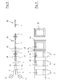
- Figure 1 shows a plan view for better illustration Flat tube 1 with a lower flat film 2, for example, with each other can be glued or welded.
- the lower flat film 2 is like this dimensioned so that it projects beyond the edge area of the flat tube 1 on all sides and thus completely surrounds it.
- the inner flat tube 1 is in the shown embodiment closed on one side by a weld 3, while the opposite side has an opening 4 in which a Teflon slide 5 is inserted to close during manufacture to prevent the opening 4.
- the two-layer inner flat tube 1 with an outer layer of LDPE and an inner layer is made of HDPE, while the outer flat film is made of LDPE or a multilayer film can be produced, the LDPA film opposite to that of the flat tube 1 comes to rest.
- the possibility of both internal and thermal effects Flat tube 1 as well as the outer flat film 2 with each other for fixation connect.
- the melting point is preferably chosen so that the outer flat film 2 due to the heat due to a higher Melting temperature is not damaged or blocked.
- one with an adhesive layer is used so that the inner flat tube 1 and the outer flat films 2 fully or at least partially glued together during production are and thus the inner flat hose in its position in relation to the outer Flat film 2 is set.
- a hot melt adhesive can preferably be used here be used.
- Figure 2 shows the arrangement of Figure 1 with an additional upper Flat film 6, which coincides with the lower flat film 2 and in the However, the illustration shown is slightly shifted to the top right and additionally a folded corner area 7 for improved presentation having.
- Figure 3 shows a finished packaging container 10 with an inner flat tube 1 and outer flat films 2, 6 after filling, the inner flat tube 1 is closed on both sides by a weld 3, 8 and the outer flat films 2, 6 by welds 12, 13, 14 and 15 additionally are closed.
- the inner flat tube 1 is closed on both sides by a weld 3, 8 and the outer flat films 2, 6 by welds 12, 13, 14 and 15 additionally are closed.
- the outer flat films 2, 6, there is the possibility that on the welds at least in the case of the outer flat films 2, 6, and instead either an adhesive coating is used or a laminated one Flat film 2, 6 is used, the a by low heat Connection with each other and with the inner flat tube 1 without any special Allows weld seam.
- FIGS. 4 and 5 show the side view and the top view Manufacturing process of the packaging container 10 according to the invention, wherein a prepared flat hose 1 is fed to a production line and at the same time from supply rolls 16, 17 a lower and upper flat film 2, 6 in is fed such that the flat tube 1 is spaced between the Flat films 2, 6 come to rest.
- pressure rollers 18, 19 can for example, when using an adhesive film, the adherence of the outer Flat films 2, 6 are effected on the flat tube 1.
- Longitudinal welding is preferred by a weld Weld 12 by means of an upper and lower heating element 20, 21 and Production of a transverse weld seam 14 by two further heating rods 22, 23.
- the packaging container is filled later 10 in the existing opening a Teflon slide 5 or Teflon strips inserted, which can be removed after welding.
- a first one The manufacturing variant shown below is based on a severing of the Weld seam 14, so that individual packaging containers 10 are formed be fed to a packaging machine. Alternatively, there is Possibility of cutting through the individual packaging containers 10 is dispensed with and these are wound on a roll that is in a Packaging system is still used. Inside the packaging machine there is the possibility of unwinding individual packaging containers 10 and after cutting the weld 14 to fill.
Landscapes
- Engineering & Computer Science (AREA)
- Mechanical Engineering (AREA)
- Food Science & Technology (AREA)
- Bag Frames (AREA)
- Packages (AREA)
- Containers Having Bodies Formed In One Piece (AREA)
- Wrappers (AREA)
Abstract
Description
Die Erfindung betrifft einen Verpackungsbehälter aus Kunststoff, bestehend aus einem Flachschlauch, der zumindest auf einer Seite verschlossen ist und einen beutelförmigen Behälter bildet.The invention relates to a packaging container made of plastic, consisting of a flat tube that is closed at least on one side and one forms bag-shaped container.
Verpackungsbehälter aus Kunststoff, die beispielsweise aus einem ein- oder mehrschichtigen Flachschlauch bestehen, werden für verschiedene Arten von Stoffen benötigt, um diese vor Verunreinigungen zu schützen oder im Fall von granulatförmigen Stoffen diese in einer bestimmten Verpackungsgröße ausliefern zu können. Insbesondere bei chemischen oder pharmazeutischen Produkten werden hierbei Verpackungssäcke verwendet, die aus einem Flachschlauch gefertigt werden. Um diese Stoffe trocken zu halten ist es üblich auf der Innenfläche des Sacks einen mit einem Trockenmittel, zum Beispiel Kieselgel, Calciumsulfat oder dergleichen gefüllten Beutel zu fixieren. Dies geschieht beispielsweise mit Hilfe einer perforierten Abdeckfolie, die unter Abdeckung des Trockenmittelbeutels auf der Innenfläche der Schlauchfolie randförmig aufgeschweißt wird. Durch eine vorhandene Perforation steht der zum Beispiel aus porösen Papier, Filz oder dergleichen bestehende Beutel beziehungsweise das Trockenmittel mit dem Innenraum des Verpackungsbeutels in Verbindung, um diesen trocken oder auf einen bestimmten Trocknungsgrad zu halten.Packaging container made of plastic, for example from a one or multilayer flat tubing are used for different types of Substances needed to protect them from contamination or in the case of granular substances in a certain packaging size to be able to deliver. Especially with chemical or pharmaceutical Products are made from packaging sacks that consist of one Flat tubing can be manufactured. It is common to keep these fabrics dry on the inside surface of the sack one with a desiccant, for example Fix silica gel, calcium sulfate or the like filled bag. This happens for example with the help of a perforated cover film Cover the desiccant bag on the inner surface of the tubular film is welded onto the edge. Due to an existing perforation for example bags made of porous paper, felt or the like or the desiccant with the interior of the packaging bag in conjunction to keep this dry or to a certain degree of dryness to keep.
Zur Fixierung des Trockenmittelbeutels auf der Innenfläche des Sacks sind hierbei verschiedene Verfahren bekannt. Bei einer Methode wird der an einem Ende verschweißte Verpackungssack umgestülpt und auf die nun freiliegende Innenfläche wird ein Trockenmittelbeutel sowie darüber eine perforierte Abdeckfolie gelegt und mit ihrem Rand auf der Innenfläche verschweißt. In einem zweiten Verfahren wird ein nur an einem Ende verschweißter Verpackungssack verwendet und ein größerer kreisrunder Ausschnitt eingearbeitet und eine zuvor perforierte Innenfolie sowie eine zweite nicht perforierte Außenfolie unter Zwischenlage eines Trockenmittels von außen am Rand des Ausschnitts verschweißt. In beiden Fällen besteht somit eine Verbindung zwischen dem Trockenmittelbeutel und dem Innenraum des Verpackungsbehälters. Derartige Abdeckfolien erstrecken sich aber nur über einen kleinen Bereich des Verpackungsbehälters ohne die Dichtigkeit des Verpackungsbehälters zu erhöhen.To fix the desiccant bag on the inner surface of the bag various methods are known. In one method, the one on The end of the sealed packaging bag turned upside down and onto the now exposed one Inside is a desiccant bag and a perforated one above it Cover foil placed and welded with its edge on the inner surface. In In a second method, a packaging bag is welded at one end only used and a larger circular cutout incorporated and a previously perforated inner film and a second non-perforated one Outer film with the interposition of a drying agent from the outside on the edge of the Cutout welded. In both cases there is a connection between the desiccant bag and the interior of the packaging container. Such cover films, however, only extend over a small one Area of the packaging container without the tightness of the packaging container to increase.
Für viele der zu verpackenden Stoffe wird aber verlangt, dass das Innere des Verpackungsbehälters vollkommen steril und frei von Fremdpartikeln ist. Weitergehende Forderungen verlangen sogar eine Gasdichtigkeit des Behälters, damit Fremdstoffe weder eindringen noch entweichen können. Hierbei ist sicherzustellen, dass der zur Aufnahme vorgesehene Verpackungsbehälter weiterhin vollkommen steril und frei von Fremdpartikeln ist. Weiterhin hat sich gezeigt, dass bei mehrschichtigen Folien an den offenen Enden des Verpackungsbehälters ein Rolleffekt entsteht, der zu einer Verformung nach innen führt und somit eine Befüllung erschwert.For many of the fabrics to be packaged, however, it is required that the inside of the Packaging container is completely sterile and free of foreign particles. Further requirements even require that the Container so that foreign matter can neither penetrate nor escape. It is important to ensure that the packaging container intended for reception is still completely sterile and free of foreign particles. Farther has been shown that in multilayer films at the open ends of the Packaging container creates a rolling effect that leads to deformation leads inside and thus complicates filling.
Der Erfindung liegt daher die Aufgabe zugrunde, einen Verpackungsbehälter zu schaffen, welcher einem hohen Innendruck widersteht, gas- und aromadicht ist und welcher eine hohe Steifigkeit aufweist und leichter zu befüllen ist.The invention is therefore based on the object of a packaging container create, which resists a high internal pressure, is gas and aroma tight and which has high rigidity and is easier to fill.
Des Weiteren liegt dem erfindungsgemäßen Verpackungsbehälter die Aufgabe zu Grunde, einen Verpackungsbehälter zur Verfügung zustellen, welcher nach Herstellung frei von fremden Partikeln und Keimen bleibt.The packaging container according to the invention also has the task to provide a packaging container, which according to Manufacturing remains free of foreign particles and germs.
Eine weitere Aufgabe der Erfindung ist es, einen Verpackungsbehälter zur Verfügung zustellen, der nicht nur frei von fremden Partikeln und Keimen hergestellt und transportiert werden kann, sondern auch verlässlich wiederverschweißt werden kann.Another object of the invention is to provide a packaging container for Make available that is not only free of foreign particles and germs can be manufactured and transported, but also reliably re-welded can be.
Noch eine Aufgabe der Erfindung ist es, ein Verpackungsmaterial zur Verfügung zu stellen, welches im verschlossenen Zustand sicher aufgewickelt werden kann.Another object of the invention is to provide a packaging material for To provide, which is securely wound up in the closed state can be.
Erfindungsgemäß ist zur Lösung der Aufgabe vorgesehen, dass der Flachschlauch außen von zwei weiteren Flachfolien randübergreifend umgeben und mit diesen kaschiert ist, welche an den Längs- und Querkanten des innen liegenden Flachschlauchs eine randseitige Überlappung ausbilden. Weitere vorteilhafte Ausgestaltungen der Erfindung ergeben sich aus den Unteransprüchen. According to the invention it is provided to achieve the object that the flat hose surrounded on the outside by two further flat foils and is laminated with these, which on the longitudinal and transverse edges of the inside form a flat overlap on the edge. Further advantageous embodiments of the invention result from the subclaims.
Durch die Verwendung einer weiteren Flachfolie mit randseitiger Überlappung und unterschiedlichen physikalischen und chemischen Eigenschaften wird sichergestellt, dass der innenliegende Flachschlauch, welcher zur Aufnahme der zu transportierenden Stoffe vorgesehen ist, zusätzlich so verschlossen werden kann, dass die dem Verpackungsmaterial vorgegebenen Randbedingungen, wie luft- und gasdichte sowie Aroma- und UV-Schutz etc. gewährleistet sind. Hierzu ist es notwendig, einen Verpackungsbehälter zur Verfügung zustellen, der gegebenenfalls geschlossen ausgeliefert wird. Durch die gewählte randübergreifende Verschweißung mit Fahnenüberstand wird ferner gewährleistet, dass die Dicke des Flachschlauches bei dem erfindungsgemäßen Verpackungsbehälter über die gesamte Breite der Flachfolie nahe zur gleich hoch ist und somit ist diese Flachfolie auch unter Ausbildung einer stabilen Wicklung aufwickelbar. Im erfindungsgemäßen Verpackungsbehälter ist über die gesamte Breite des innenliegenden Flachschlauches eine gleichstarke äußere Folienschicht gelegt, sodass erreicht werden kann, dass der innenliegende Flachschlauch von außen durch die Außenfolie hindurch verschweißt werden kann. Diese Verschweißung kann auf der gesamten Breite mit der gleichen Temperatur und einem vergleichbaren Wärmefluss erfolgen, sodass keine ungleichmäßige Verschweißung des inneren Flachschlauches quer zu Maschinenrichtung auftritt.By using another flat film with overlap on the edge and different physical and chemical properties ensures that the inner flat hose, which is used for receiving of the substances to be transported is additionally sealed can be that the boundary conditions given to the packaging material, such as air and gas tight as well as aroma and UV protection etc. guaranteed are. For this it is necessary to have a packaging container available to deliver, which may be delivered closed. Through the selected cross-border welding with tab overhang is also ensures that the thickness of the flat tube in the invention Packaging container over the entire width of the flat film close to is the same height and thus this flat film is also under formation of one stable winding can be wound up. In the packaging container according to the invention is one over the entire width of the inner flat hose equally thick outer layer of film, so that can be achieved the inner flat tube from the outside through the outer film can be welded. This weld can cover the entire width with the same temperature and a comparable heat flow, so that there is no uneven welding of the inner flat hose cross-machine direction occurs.
Erst durch die erfindungsgemäße Kaschierung des innenliegenden Flachschlauches mit der außenliegenden Folie und der erfindungsgemäßen Folienanordnung wird erreicht, dass der Verpackungsbehälter sowohl eine hohe Steifigkeit, besonders am Öffnungsrand, eine Gas- und Aromadichtigkeit, eine hohe Widerstandskraft gegenüber hohen Innendrücken, wie er bei der Lagerung vieler übereinanderliegender gefüllter Verpackungen auftreten kann, eine Partikel- und Keimarmut, auch bei Lagerung, und auch eine sichere Aufwickelbarkeit aufweist. Speziell durch die Kaschierung wird erreicht, dass der Wärmefluss durch die Verbundlagen bei der Verschweißung des Innenschlauches hoch genug ist, dass der Innenschlauch, der eine höhere Schmelztemperatur als das äußere Folienmaterial aufweist, hoch genug ist, um den Innenschlauch sicher zu verschweißen ohne, dass bei diesem Vorgang das Außenmaterial zerfließt. In besonderem Maße wird durch die erfindungsgemäße Lagenanordnung und -kaschierung erreicht, dass der innere Flachschlauch bei Bedarf noch während der Herstellung durch eine Verschweißung durch das äußere Folienmaterial verschweißt werden kann, sodass der innere Flachschlauch weitgehend keim- und partikelfrei bleibt und bei Befüllung in einer Befüllungsmaschine an einer Seite aufgeschlitzt wird, wobei an den Schlitzrändern durch die Steifigkeit der äußeren Folienlage kein Rolleffekt auftritt, sodass eine maschinelle Befüllung ohne besondere Maßnahmen zur Öffnungsrandstabilisierung notwendig sind. Des Weiteren kann der innere Flachschlauch mit einer gattungsgemäßen Schweißmaschine wieder verschweißt werden, ohne dass Kanülenbildungen oder unzureichende Verschweißungen zu erwarten sind. Zum Befüllen des oben beschriebenen Verpackungsbeutels kommen hauptsächlich zwei Verfahren zur Anwendung. Zunächst besteht die Möglichkeit eine direkte Befüllung eines Flachschlauchs von einer Vorratsrolle in einem Verpackungsautomaten vorzunehmen. Eine weitere Möglichkeit besteht darin, die Befüllung eines einzelnen vorkonfektionierten Flachbeutels in einer Verpackungsanlage vorzusehen. In beiden Fällen tritt normalerweise die Problematik auf, dass der Verbundflachschlauch beziehungsweise Verbundflachbeutel einen relativ starken Rolleffekt an der offenen Seite nach innen aufweist, der beim Befüllvorgang hinderlich sein kann, wenn dieser nicht sogar unmöglich wird. Durch das erfindungsgemäße Verfahren wird überraschender Weise der Vorteil erreicht, dass der Rolleffekt bei einer Vorkonfektionierung in der erfindungsgemäßen Art nicht eintritt und eine optimale Befüllung in einem Verpackungsautomaten möglich wird.Only through the lamination of the inner flat tube according to the invention with the outer film and the invention Film arrangement ensures that the packaging container is both high Rigidity, especially at the opening edge, gas and aroma tightness, one high resistance to high internal pressures, as in the Storage of many stacked filled packages can occur, a lack of particles and germs, even during storage, and also a safe one Has windability. The lamination ensures that the heat flow through the composite layers when welding the inner tube is high enough that the inner tube is a higher Melting temperature than the outer sheet material is high enough to to securely weld the inner tube without this Outer material flows away. To a particular extent, the invention Layer arrangement and lamination achieved that the inner flat tube if necessary, during the production by welding through the outer film material can be welded so that the inner flat tube remains largely germ and particle free and when filled in one Filling machine is slit on one side, with the slit edges due to the stiffness of the outer film layer, no rolling effect occurs, so that mechanical filling without special measures to stabilize the opening edge are necessary. The inner flat hose can also be used a generic welding machine can be welded again without that cannula formation or insufficient welding can be expected are. Come to fill the packaging bag described above mainly two methods of application. First there is the possibility direct filling of a flat hose from a supply roll in one To make packaging machines. Another option is the filling of a single pre-assembled flat bag in one To provide packaging system. In both cases this usually occurs Problem on that the composite flat tube or composite flat bag a relatively strong rolling effect on the open side inwards has, which can be an obstacle to the filling process, if not becomes impossible. The method according to the invention is more surprising Way the advantage achieved that the roll effect in a pre-assembly in of the type according to the invention does not occur and optimal filling in one Packaging machine becomes possible.
Um sicherzustellen, dass der innere Aufnahmebehälter vollständig von der äußeren Flachfolie umgeben ist, wird eine randseitige Überlappung ausgebildet. Die Verbindung des inneren Flachschlauchs mit den äußeren Flachfolien kann hierbei durch eine Verklebung mittels Schmelzklebers oder Verschweißung aufgrund von Wärmeeinwirkung hergestellt werden, wobei zum Befüllen des inneren Flachschlauchs sowohl in dem inneren als auch den äußeren Flachfolien eine Einfüllöffnung vorhanden ist, die nachträglich verschließbar sind. Vorzugsweise wird hierbei die Temperatur zum Verschließen des inneren Flachschlauchs beziehungsweise zum Kaschieren mit der äußeren Flachfolie so gewählt, dass die Temperatur zum Kaschieren niedriger liegt, als die zum Verschließen des Flachschlauchs. Soweit jedoch besondere Kunststoffmaterialien verwendet werden, die möglicherweise annähernd gleiche Schmelztemperaturbereiche aufweisen, kann auf der Seite wo der Behälter zum Befüllen offen bleiben soll beispielsweise ein Teflonschieber eingeschoben werden, der eine Verbindung des inneren Flachschlauchs beziehungsweise eine Verbindung der äußeren Flachfolien verhindert. In ähnlicher Weise kann bei der Verwendung eines Schmelzklebers vorgegangen werden.To ensure that the inner receptacle is completely off the outer flat film is surrounded, an edge-side overlap is formed. The connection of the inner flat tube with the outer flat foils can here by gluing with hot melt adhesive or welding be produced due to the action of heat, whereby to fill the inner flat hose in both the inner and the outer Flat films a filling opening is available, which can be closed later are. The temperature for closing the interior is preferred Flat hose or for lamination with the outer flat film chosen so that the temperature for lamination is lower than that for Close the flat hose. So much for special plastic materials used, which may have approximately the same melting temperature ranges can have on the side where the container is open for filling For example, a Teflon slide should remain inserted, the one Connection of the inner flat hose or a connection of the outer flat foils prevented. Similarly, when using of a hot melt adhesive.
Damit die randseitige Überlappung gleichmäßig gewährleistet ist und eine unerwünschte Verschiebung des inneren Flachschlauchs nicht eintreten kann ist vorgesehen, dass der innere Flachschlauch und die äußeren Flachfolien zumindest partiell miteinander verklebt oder verschweißt sind. Somit wird sichergestellt, dass der innere Flachschlauch gegenüber dem äußeren Flachfolien fest fixiert ist.So that the edge overlap is evenly guaranteed and one undesirable displacement of the inner flat hose cannot occur it is provided that the inner flat tube and the outer flat films are at least partially glued or welded together. Thus ensures that the inner flat hose is opposite the outer one Flat film is firmly fixed.
Zur kostengünstigen maschinellen Herstellung der erfindungsgemäßen Verpackungsbehälter ist vorgesehen, dass der innere einseitig verschlossene Flachschlauch in Form von einzelnen beutelförmigen Behältern in zwei beidseitigen äußeren Flachfolien beabstandet aufgenommen sind, wobei sich die Flachfolien im Bereich zwischen dem inneren beutelförmigen Flachschlauch berühren. Somit wird eine vollständige Überlappung der äußeren Flachfolien um den inneren Flachschlauch gewährleistet und es besteht darüber hinaus die Möglichkeit derartig ausgebildete Verpackungsbehälter als Rollenware herzustellen, die vorkonfektioniert ist und zum Gebrauch einzelner Verpackungsbehälter nach Durchtrennen der äußeren Flachfolie verwendet werden können. Nach dem Befüllen wird sodann die innere Schlauchfolie verschlossen, beispielsweise verschweißt, und anschließend die äußeren Flachfolien im Überlappungsbereich zusätzlich verklebt oder verschweißt. Damit keine Gasdiffusion stattfinden kann, können die äußeren Folien vorzugsweise aus einer kaschierten Folie oder einer Aluminiumfolie bestehen.For the inexpensive mechanical production of the invention Packaging container is provided that the inner one-sided sealed Flat tube in the form of individual bag-shaped containers in two outer flat films on both sides are received spaced apart, with the flat films in the area between the inner bag-shaped flat tube touch. Thus there is a complete overlap of the outer flat films to ensure the inner flat tube and there is also the Possibility of packaging containers designed in this way as roll goods to manufacture, which is pre-assembled and for the use of individual packaging containers after cutting through the outer flat film can. After filling, the inner tubular film is then closed, welded, for example, and then the outer flat films in Overlap area additionally glued or welded. So none Gas diffusion can take place, the outer films can preferably be made of a laminated foil or an aluminum foil.
In besonderer Ausgestaltung der Erfindung ist vorgesehen, dass der innere Flachschlauch und die äußeren Flachfolien aus einer mehrschichtigen Folie bestehen, wobei der zweischichtige innere Flachschlauch mit einer Außenschicht aus LDPE (Low Density Polyäthylen) und einer Innenschicht aus HDPE (High Density Polyäthylen) hergestellt wird und die äußeren Flachfolien aus LDPE oder einer mehrschichtigen Folie hergestellt werden, wodurch der innere Flachschlauch mit den äußeren Flachfolien durch Temperatureinwirkung miteinander verschweißt werden kann, wenn die beiden LDPE-Folien gegenüber liegen. Hierbei wird der Schmelzpunkt so gewählt, dass die äußeren Flachfolien durch die Wärmeeinwirkung aufgrund einer höheren Schmelztemperatur nicht beschädigt oder verblockt werden. In a special embodiment of the invention it is provided that the inner Flat tube and the outer flat films from a multi-layer film exist, the two-layer inner flat tube with an outer layer made of LDPE (Low Density Polyethylene) and an inner layer made of HDPE (High Density Polyethylene) is manufactured and the outer flat films LDPE or a multi-layer film can be made, creating the inner Flat tube with the outer flat foils due to temperature can be welded together if the two LDPE films opposite. The melting point is chosen so that the outer Flat foils due to the effects of heat due to a higher melting temperature not be damaged or blocked.
Der besondere Vorteil des erfindungsgemäßen Verpackungsbehälters aus Kunststoff besteht darin, dass die Verpackungsbeutel mit einer zusätzlichen Schutzfolie, die beispielsweise gas- und luftdicht ausgebildet sein kann, versehen werden, und zwar in der Form, dass ein überlappender Randbereich entsteht, der eine vollständige Einfassung des innenliegenden Flachschlauchs ermöglicht. Ein weiterer wesentlicher Vorteil besteht darin, dass eine Vorkonfektionierung der Verpackungsbehälter erfolgen kann und diese als Rollenware ausgeliefert werden, sodass nach einem Durchtrennen der äußeren Flachfolie einzelne Verpackungsbeutel entstehen, die die vorgenannten Eigenschaften aufweisen.The particular advantage of the packaging container according to the invention Plastic is the packaging bag with an additional Protective film, which can be made, for example, gas and airtight, be provided, in the form that an overlapping edge area arises, which is a complete surround of the inner flat hose allows. Another major advantage is that it is pre-assembled the packaging container can be made and this as a roll are delivered so that after cutting the outer flat film Individual packaging bags arise that have the aforementioned properties exhibit.
Die Erfindung wird im Weiteren anhand der Figuren näher erläutert.The invention is explained in more detail below with reference to the figures.
Es zeigt
Figur 1- in einer Draufsicht einen Flachschlauch mit unterer Flachfolie und einem eingeschobenen Teflonschieber während des Herstellungsprozesses,
Figur 2- einen erfindungsgemäßen Verpackungsbehälter gemäß
Figur 1, bestehend aus dem Flachschlauch mit beidseitigen Flachfolien, wobei die obere Flachfolie zur besseren Darstellung in einem Eckbereich umgeschlagen und leicht verschoben ist, Figur 3- einen erfindungsgemäßen Verpackungsbehälter, bestehend aus einem Flachschlauch mit zwei außen liegenden Flachfolien, wobei der Flachschlauch beidseitig durch Wärmeeinwirkung verschlossen ist und die äußeren Flachfolien einseitig verschlossen sind,
Figur 4- einen schematischen Ablaufplan für die Herstellung der Verpackungsbehälter und
Figur 5- eine Draufsicht gemäß
Figur 4 während des Herstellungsprozesses.
- Figure 1
- in a plan view a flat tube with a lower flat film and an inserted Teflon slide during the manufacturing process,
- Figure 2
- 2 shows a packaging container according to the invention according to FIG. 1, consisting of the flat tube with flat films on both sides, the upper flat film being folded over and slightly shifted in a corner area for better illustration,
- Figure 3
- a packaging container according to the invention, consisting of a flat tube with two outer flat foils, the flat tube being closed on both sides by the action of heat and the outer flat foils being closed on one side,
- Figure 4
- a schematic flow chart for the manufacture of the packaging container and
- Figure 5
- a plan view of Figure 4 during the manufacturing process.
Figur 1 zeigt in einer Draufsicht zur besseren Veranschaulichung einen
Flachschlauch 1 mit einer unteren Flachfolie 2, die beispielsweise miteinander
verklebt oder aber auch verschweißt sein können. Die untere Flachfolie 2 ist so
bemessen, dass sie den Randbereich des Flachschlauchs 1 allseitig überragt
und diesen somit vollständig umgibt. Der innere Flachschlauch 1 ist im
gezeigten Ausführungsbeispiel einseitig durch eine Schweißnaht 3 verschlossen,
während die gegenüber liegende Seite eine Öffnung 4 aufweist, in der ein
Teflonschieber 5 eingeschoben ist, um während der Fertigung ein Verschließen
der Öffnung 4 zu verhindern. Vorzugsweise werden sowohl als Flachschlauch 1
und Flachfolie 2 mehrschichtige Folien eingesetzt, wobei der zweischichtige
innere Flachschlauch 1 mit einer Außenschicht aus LDPE und einer Innenschicht
aus HDPE hergestellt wird, während die äußere Flachfolie aus LDPE
oder einer mehrschichtigen Folie hergestellt werden kann, deren LDPA-Folie
gegenüber der des Flachschlauchs 1 zu liegen kommt. Hierdurch besteht
beispielsweise die Möglichkeit durch Temperatureinwirkung sowohl den inneren
Flachschlauch 1 als auch die äußere Flachfolie 2 miteinander zur Fixierung zu
verbinden. Vorzugsweise wird der Schmelzpunkt hierbei so gewählt, dass die
äußere Flachfolie 2 durch die Wärmeeinwirkung aufgrund einer höheren
Schmelztemperatur nicht beschädigt oder verblockt wird. Alternativ besteht die
Möglichkeit, dass anstelle einer Mehrschichtfolie eine solche mit Klebeschicht
verwendet wird, sodass der innere Flachschlauch 1 und die äußeren Flachfolien
2 während der Fertigung vollflächig oder zumindest partiell miteinander verklebt
sind und somit der innere Flachschlauch in seiner Lage gegenüber der äußeren
Flachfolie 2 festgelegt ist. Hierbei kann vorzugsweise ein Schmelzkleber
eingesetzt werden.Figure 1 shows a plan view for better illustration
Figur 2 zeigt die Anordnung gemäß Figur 1 mit einer zusätzlichen oberen
Flachfolie 6, die zur Deckung mit der unteren Flachfolie 2 kommt und in der
gezeigten Darstellung jedoch leicht nach rechts oben verschoben ist und
zusätzlich einen umgeklappten Eckbereich 7 zur verbesserten Darstellung
aufweist.Figure 2 shows the arrangement of Figure 1 with an additional upper
Figur 3 zeigt einen fertigen Verpackungsbehälter 10 mit innerem Flachschlauch
1 und äußeren Flachfolien 2, 6 nach dem Befüllen, wobei der innere Flachschlauch
1 beidseitig durch eine Schweißnaht 3, 8 verschlossen ist und die
äußeren Flachfolien 2, 6 durch Schweißnähte 12, 13, 14 und 15 zusätzlich
verschlossen sind. Alternativ besteht die Möglichkeit, dass auf die Schweißnähte
zumindest bei den äußeren Flachfolien 2, 6 verzichtet wird und stattdessen
entweder eine Klebebeschichtung verwendet wird oder aber eine kaschierte
Flachfolie 2, 6 verwendet wird, die durch geringe Wärmeeinwirkung eine
Verbindung miteinander und mit dem inneren Flachschlauch 1 ohne besondere
Schweißnaht ermöglicht. Von den verschiedenen Varianten ist nur die mit
Schweißnähten 12, 13, 14, 15 für die äußeren Flachfolien 2, 6 sowie für den
inneren Flachschlauch 1 mit den Schweißnähten 3, 11 dargestellt.Figure 3 shows a
Figur 4 und 5 zeigt in einer Seitenansicht beziehungsweise Draufsicht den
Fertigungsprozess der erfindungsgemäßen Verpackungsbehälter 10, wobei ein
vorbereiteter Flachschlauch 1 einer Fertigungsstraße zugeführt wird und
gleichzeitig von Vorratsrollen 16, 17 eine untere und obere Flachfolie 2, 6 in
derart zugeführt wird, dass der Flachschlauch 1 beabstandet zwischen den
Flachfolien 2, 6 zu liegen kommt. Mittels Andruckrollen 18, 19 kann hierbei
beispielsweise bei Verwendung einer Klebefolie das Anhaften der äußeren
Flachfolien 2, 6 auf dem Flachschlauch 1 bewirkt werden. Soweit jedoch eine
Schweißnaht vorgezogen wird erfolgt eine Längsverschweißung durch eine
Schweißnaht 12 mittels eines oberen und unteren Heizstabes 20, 21 und die
Herstellung einer querliegenden Schweißnaht 14 durch zwei weitere Heizstäbe
22, 23. Während der Verschweißung wird zum späteren Befüllen der Verpackungsbehälter
10 in die vorhandene Öffnung ein Teflonschieber 5 oder ein
Teflonstreifen eingelegt, der nach dem Verschweißen entfernt werden kann.
Somit entsteht ein einseitig offener Verpackungsbehälter 10, der nach dem
Befüllen durch weitere Schweißvorgänge verschlossen wird. Eine erste
aufgezeigte Herstellungsvariante geht im Weiteren von einer Durchtrennung der
Schweißnaht 14 aus, sodass einzelne Verpackungsbehälter 10 entstehen, die
einer Verpackungsmaschine zugeführt werden. Alternativ besteht die
Möglichkeit, dass auf eine Durchtrennung der einzelnen Verpackungsbehälter
10 verzichtet wird und diese auf eine Rolle aufgewickelt werden, die in eine
Verpackungsanlage weiter verwendet wird. Innerhalb der Verpackungsmaschine
besteht so die Möglichkeit einzelne Verpackungsbehälter 10 abzuwickeln
und nach Durchtrennen der Schweißnaht 14 zu Befüllen.FIGS. 4 and 5 show the side view and the top view
Manufacturing process of the
Alternativ besteht die Möglichkeit anstelle der Schweißvorrichtung die untere
und obere Flachfolie 2, 6 mit einer dem Flachschlauch 1 zugewandten
Klebefolie zu beschichten, sodass die beiden äußeren Flachfolien 2, 6
unmittelbar auf der flachen Oberseite des Flachschlauchs 1 haften und im
Randbereich aufeinander liegen. Alternativ besteht die Möglichkeit einen
Schmelzkleber einzusetzen. Im Falle der Verwendung einer kaschierten Folie
mit Schmelzkleber kann durch eine großflächige Temperatureinwirkung eine
Verbindung des inneren Flachschlauchs 1 mit den äußeren Flachfolien 2
bewirkt werden, wobei bei geeigneter Temperaturwahl die Verbindung
hergestellt wird, ohne dass der innere Flachschlauch 1 allseitig verschlossen
wird. Zu diesem Zweck ist es erforderlich, dass der Flachschlauch 1 zumindest
einseitig vorher verschweißt wird. Nach dem Befüllen des Verpackungsbehälters
1 kann durch erhöhte Temperatureinwirkung im Einfüllbereich des
Verpackungsbehälters 1 ein Verschließen des inneren Flachschlauchs 1 sowie
der äußeren Flachfolien 2, 6 erreicht werden. Alternatively there is the possibility to use the lower one instead of the welding device
and upper
- 11
- Flachschlauchflat hose
- 22
- Flachfolieflat film
- 33
- SchweißnahtWeld
- 44
- Öffnungopening
- 55
- TeflonschieberTeflon slider
- 66
- Flachfolieflat film
- 77
- Eckbereichcorner
- 88th
- SchweißnahtWeld
- 1010
- Verpackungsbehälterpackaging container
- 1111
- SchweißnahtWeld
- 1212
- SchweißnahtWeld
- 1313
- SchweißnahtWeld
- 1414
- SchweißnahtWeld
- 1616
- Vorratsrollesupply roll
- 1717
- Vorratsrollesupply roll
- 1818
- Andruckrollepinch
- 1919
- Andruckrollepinch
- 2020
- Heizstabheater
- 2121
- Heizstabheater
- 2222
- Heizstabheater
- 2323
- Heizstabheater
Claims (8)
dadurch gekennzeichnet, dass der Flachschlauch (1) außen von zwei weiteren Flachfolien (2, 6) randübergreifend umgeben und mit diesen kaschiert ist, welche an den Längs- und Querkanten des innen liegenden Flachschlauchs (1) eine randseitige Überlappung ausbilden.Packaging container (10) made of plastic, consisting of a flat tube (1) which is closed at least on one side and forms a bag-shaped container,
characterized in that the flat tube (1) is surrounded on the outside by two further flat foils (2, 6) and is laminated with these, which form an edge-side overlap on the longitudinal and transverse edges of the inner flat tube (1).
dadurch gekennzeichnet, dass der innere Flachschlauch (1) und die weiteren Flachfolien (2, 6) eine korrespondierende Einfüllöffnung (4) aufweisen und durch zumindest eine, vorzugsweise zwei getrennte Verbindungsnähte, beispielsweise Klebeoder Schweißnähte (13, 18), nach der Befüllung verschließbar sind.Packaging container according to claim 1,
characterized in that the inner flat tube (1) and the further flat foils (2, 6) have a corresponding filling opening (4) and can be closed after filling by at least one, preferably two separate connecting seams, for example adhesive or weld seams (13, 18) ,
dadurch gekennzeichnet, dass der innere Flachschlauch (1) und die äußeren Flachfolien (2, 6) zumindest partiell miteinander verklebt oder verschweißt sind.Packaging container according to claim 1 or 2,
characterized in that the inner flat tube (1) and the outer flat films (2, 6) are at least partially glued or welded to one another.
dadurch gekennzeichnet, dass der innere einseitig verschlossene Flachschlauch (1) in Form von einzelnen beutelförmigen Behältern in zwei beidseitigen äußeren Flachfolie (2, 6) beabstandet aufgenommen sind, wobei sich die Flachfolien (2, 6) im Bereich zwischen den inneren beutelförmigen Behältern berühren.Packaging container according to one or more of claims 1, 2 or 3,
characterized in that the inner flat tube (1), which is closed on one side, is accommodated in the form of individual bag-shaped containers spaced apart in two outer flat films (2, 6) on both sides, the flat films (2, 6) touching in the area between the inner bag-shaped containers.
dadurch gekennzeichnet, dass mehrere Behälter als Rollenware vorkonfektioniert sind und zum Gebrauch einzelnen Behälter nach einem Durchtrennen der äußeren Flachfolie (2, 6) verwendbar sind.Packaging container according to one or more of claims 1 to 4,
characterized in that several containers are pre-assembled as rolls and individual containers can be used after cutting through the outer flat film (2, 6).
dadurch gekennzeichnet, dass die äußere Flachfolie (2, 6) aus einer kaschierten Folie, insbesondere Aluminiumfolie, besteht.Packaging container according to one or more of claims 1 to 5,
characterized in that the outer flat film (2, 6) consists of a laminated film, in particular aluminum film.
dadurch gekennzeichnet, dass der innere Flachschlauch (1) und die äußeren Flachfolien (2, 6) aus einer mehrschichtigen Folie bestehen.Packaging container according to claim 6,
characterized in that the inner flat tube (1) and the outer flat films (2, 6) consist of a multilayer film.
dadurch gekennzeichnet, dass der innere Flachschlauch (1) aus einer zweischichtigen Folie mit einer Außenschicht aus LDPE und einer Innenschicht aus HDPE besteht und die äußere Flachfolie (2, 6) aus LDPE oder einer mehrschichtigen Folie mit einer Innenseite aus LDPE besteht.Packaging container according to one or more of claims 1 to 7,
characterized in that the inner flat tube (1) consists of a two-layer film with an outer layer made of LDPE and an inner layer made of HDPE and the outer flat film (2, 6) consists of LDPE or a multilayer film with an inner side made of LDPE.
Applications Claiming Priority (2)
| Application Number | Priority Date | Filing Date | Title |
|---|---|---|---|
| DE10255521 | 2002-11-28 | ||
| DE10255521A DE10255521A1 (en) | 2002-11-28 | 2002-11-28 | Plastic packaging containers |
Publications (3)
| Publication Number | Publication Date |
|---|---|
| EP1424293A2 true EP1424293A2 (en) | 2004-06-02 |
| EP1424293A3 EP1424293A3 (en) | 2005-01-19 |
| EP1424293B1 EP1424293B1 (en) | 2007-06-06 |
Family
ID=32240494
Family Applications (1)
| Application Number | Title | Priority Date | Filing Date |
|---|---|---|---|
| EP03027250A Expired - Lifetime EP1424293B1 (en) | 2002-11-28 | 2003-11-28 | Plastic packaging container |
Country Status (3)
| Country | Link |
|---|---|
| EP (1) | EP1424293B1 (en) |
| AT (1) | ATE364019T1 (en) |
| DE (2) | DE10255521A1 (en) |
Families Citing this family (1)
| Publication number | Priority date | Publication date | Assignee | Title |
|---|---|---|---|---|
| DE102005051640B4 (en) * | 2005-10-26 | 2010-10-14 | Nordenia Deutschland Gronau Gmbh | Packaging bags, in particular for chocolate goods |
Citations (6)
| Publication number | Priority date | Publication date | Assignee | Title |
|---|---|---|---|---|
| GB515014A (en) * | 1937-08-04 | 1939-11-23 | Leroy Lincoln Salfisberg | Improvements in packages for storing and dispensing powders, pastes, liquids and like fluid substances |
| FR951977A (en) * | 1943-02-13 | 1949-11-07 | Waterproof packaging | |
| US3838794A (en) * | 1972-07-10 | 1974-10-01 | H Markham | Package for storing and dispensing liquids |
| EP0778202A1 (en) * | 1995-12-06 | 1997-06-11 | Tetra Laval Holdings & Finance SA | An aseptic bag for separating off liquid |
| DE19600530A1 (en) * | 1996-01-10 | 1997-07-17 | Nutrichem Diaet & Pharma Gmbh | Disposable bag for storing e.g. blood, blood plasma, etc. |
| EP1247757A1 (en) * | 2001-04-06 | 2002-10-09 | August Töpfer & Co. (GmbH & Co.) | Packaging for bath salt |
Family Cites Families (2)
| Publication number | Priority date | Publication date | Assignee | Title |
|---|---|---|---|---|
| GB932524A (en) * | 1961-12-05 | 1963-07-31 | Spiral Mfg Proprietary Ltd | Tubular moisture-proof packaging material and method of and apparatus for its manufacture |
| GB2074128B (en) * | 1980-04-18 | 1984-02-15 | Pillopak Bv | Mailing-containers and a method of manufacture thereof |
-
2002
- 2002-11-28 DE DE10255521A patent/DE10255521A1/en not_active Withdrawn
-
2003
- 2003-11-28 AT AT03027250T patent/ATE364019T1/en not_active IP Right Cessation
- 2003-11-28 EP EP03027250A patent/EP1424293B1/en not_active Expired - Lifetime
- 2003-11-28 DE DE50307413T patent/DE50307413D1/en not_active Expired - Lifetime
Patent Citations (6)
| Publication number | Priority date | Publication date | Assignee | Title |
|---|---|---|---|---|
| GB515014A (en) * | 1937-08-04 | 1939-11-23 | Leroy Lincoln Salfisberg | Improvements in packages for storing and dispensing powders, pastes, liquids and like fluid substances |
| FR951977A (en) * | 1943-02-13 | 1949-11-07 | Waterproof packaging | |
| US3838794A (en) * | 1972-07-10 | 1974-10-01 | H Markham | Package for storing and dispensing liquids |
| EP0778202A1 (en) * | 1995-12-06 | 1997-06-11 | Tetra Laval Holdings & Finance SA | An aseptic bag for separating off liquid |
| DE19600530A1 (en) * | 1996-01-10 | 1997-07-17 | Nutrichem Diaet & Pharma Gmbh | Disposable bag for storing e.g. blood, blood plasma, etc. |
| EP1247757A1 (en) * | 2001-04-06 | 2002-10-09 | August Töpfer & Co. (GmbH & Co.) | Packaging for bath salt |
Also Published As
| Publication number | Publication date |
|---|---|
| DE10255521A1 (en) | 2004-06-24 |
| EP1424293A3 (en) | 2005-01-19 |
| ATE364019T1 (en) | 2007-06-15 |
| DE50307413D1 (en) | 2007-07-19 |
| EP1424293B1 (en) | 2007-06-06 |
Similar Documents
| Publication | Publication Date | Title |
|---|---|---|
| DE69423199T2 (en) | Wrapping device | |
| EP1607339B1 (en) | Vented plastic bag | |
| EP2464510B1 (en) | Method for producing a sack or a bag having plastic non-woven material | |
| EP1910176B1 (en) | Ventilatable bag | |
| DE4303894A1 (en) | Packaging means fillable with a bulk material and flat in the empty state, as well as method and apparatus for producing the flat packaging means and deaerating and closing the filled packaging means | |
| DE69505106T2 (en) | SEALED CONTAINER, IN PARTICULAR TUBE BAG, METHOD FOR ITS PRODUCTION, METHOD FOR ITS FILLING WITH A LIQUID | |
| DE3413352A1 (en) | PACKAGING AND METHOD FOR THEIR PRODUCTION | |
| DE3810555A1 (en) | TUBULAR CONTAINER MADE OF PLASTIC MATERIAL AND METHOD FOR THE PRODUCTION THEREOF | |
| DE2254640B2 (en) | FLAT FOLDING BAG | |
| CH642923A5 (en) | METHOD FOR THE CONTINUOUS PRODUCTION OF PACKAGE CONTAINERS AND DEVICE FOR CARRYING OUT THIS. | |
| DE2946739A1 (en) | LAYERED LAMINATED PACKAGING MATERIAL AND METHOD FOR THE PRODUCTION THEREOF | |
| EP2752371B1 (en) | Valve bag | |
| EP2792609A1 (en) | Packaging container for bulk materials | |
| WO2012025413A2 (en) | Sack and method and device for producing sacks | |
| EP2991911B1 (en) | Bag made of paper | |
| EP1882637B1 (en) | Packing container | |
| DE2351189C3 (en) | Packaging with a plastic inner container and an envelope surrounding it | |
| DE19720112C2 (en) | Process for fixing a desiccant bag in a tubular plastic packaging bag and packaging bag produced thereafter | |
| EP1424293B1 (en) | Plastic packaging container | |
| EP2186742A1 (en) | Film packaging bag, especially for powdery, dusty filling goods | |
| EP3519312A1 (en) | Valve bag and method and system for producing a valve bag | |
| DE3040418A1 (en) | TOBACCO BAG WITH A BOXED BAG AND METHOD FOR THE PRODUCTION THEREOF | |
| CH661487A5 (en) | METHOD FOR PRODUCING A PACKAGING CONTAINER. | |
| EP3107816B1 (en) | Bag | |
| EP1422155B1 (en) | Transport container |
Legal Events
| Date | Code | Title | Description |
|---|---|---|---|
| PUAI | Public reference made under article 153(3) epc to a published international application that has entered the european phase |
Free format text: ORIGINAL CODE: 0009012 |
|
| AK | Designated contracting states |
Kind code of ref document: A2 Designated state(s): AT BE BG CH CY CZ DE DK EE ES FI FR GB GR HU IE IT LI LU MC NL PT RO SE SI SK TR |
|
| AX | Request for extension of the european patent |
Extension state: AL LT LV MK |
|
| PUAL | Search report despatched |
Free format text: ORIGINAL CODE: 0009013 |
|
| AK | Designated contracting states |
Kind code of ref document: A3 Designated state(s): AT BE BG CH CY CZ DE DK EE ES FI FR GB GR HU IE IT LI LU MC NL PT RO SE SI SK TR |
|
| AX | Request for extension of the european patent |
Extension state: AL LT LV MK |
|
| 17P | Request for examination filed |
Effective date: 20050712 |
|
| AKX | Designation fees paid |
Designated state(s): AT BE BG CH CY CZ DE DK EE ES FI FR GB GR HU IE IT LI LU MC NL PT RO SE SI SK TR |
|
| 17Q | First examination report despatched |
Effective date: 20060707 |
|
| GRAP | Despatch of communication of intention to grant a patent |
Free format text: ORIGINAL CODE: EPIDOSNIGR1 |
|
| GRAS | Grant fee paid |
Free format text: ORIGINAL CODE: EPIDOSNIGR3 |
|
| GRAA | (expected) grant |
Free format text: ORIGINAL CODE: 0009210 |
|
| AK | Designated contracting states |
Kind code of ref document: B1 Designated state(s): AT BE BG CH CY CZ DE DK EE ES FI FR GB GR HU IE IT LI LU MC NL PT RO SE SI SK TR |
|
| PG25 | Lapsed in a contracting state [announced via postgrant information from national office to epo] |
Ref country code: FI Free format text: LAPSE BECAUSE OF FAILURE TO SUBMIT A TRANSLATION OF THE DESCRIPTION OR TO PAY THE FEE WITHIN THE PRESCRIBED TIME-LIMIT Effective date: 20070606 |
|
| REG | Reference to a national code |
Ref country code: GB Ref legal event code: FG4D Free format text: NOT ENGLISH |
|
| REG | Reference to a national code |
Ref country code: CH Ref legal event code: EP |
|
| REG | Reference to a national code |
Ref country code: IE Ref legal event code: FG4D Free format text: LANGUAGE OF EP DOCUMENT: GERMAN |
|
| REF | Corresponds to: |
Ref document number: 50307413 Country of ref document: DE Date of ref document: 20070719 Kind code of ref document: P |
|
| GBT | Gb: translation of ep patent filed (gb section 77(6)(a)/1977) |
Effective date: 20070815 |
|
| PG25 | Lapsed in a contracting state [announced via postgrant information from national office to epo] |
Ref country code: SE Free format text: LAPSE BECAUSE OF FAILURE TO SUBMIT A TRANSLATION OF THE DESCRIPTION OR TO PAY THE FEE WITHIN THE PRESCRIBED TIME-LIMIT Effective date: 20070906 |
|
| PG25 | Lapsed in a contracting state [announced via postgrant information from national office to epo] |
Ref country code: ES Free format text: LAPSE BECAUSE OF FAILURE TO SUBMIT A TRANSLATION OF THE DESCRIPTION OR TO PAY THE FEE WITHIN THE PRESCRIBED TIME-LIMIT Effective date: 20070917 |
|
| ET | Fr: translation filed | ||
| NLV1 | Nl: lapsed or annulled due to failure to fulfill the requirements of art. 29p and 29m of the patents act | ||
| REG | Reference to a national code |
Ref country code: IE Ref legal event code: FD4D |
|
| PG25 | Lapsed in a contracting state [announced via postgrant information from national office to epo] |
Ref country code: CZ Free format text: LAPSE BECAUSE OF FAILURE TO SUBMIT A TRANSLATION OF THE DESCRIPTION OR TO PAY THE FEE WITHIN THE PRESCRIBED TIME-LIMIT Effective date: 20070606 Ref country code: IE Free format text: LAPSE BECAUSE OF FAILURE TO SUBMIT A TRANSLATION OF THE DESCRIPTION OR TO PAY THE FEE WITHIN THE PRESCRIBED TIME-LIMIT Effective date: 20070606 Ref country code: SI Free format text: LAPSE BECAUSE OF FAILURE TO SUBMIT A TRANSLATION OF THE DESCRIPTION OR TO PAY THE FEE WITHIN THE PRESCRIBED TIME-LIMIT Effective date: 20070606 Ref country code: BG Free format text: LAPSE BECAUSE OF FAILURE TO SUBMIT A TRANSLATION OF THE DESCRIPTION OR TO PAY THE FEE WITHIN THE PRESCRIBED TIME-LIMIT Effective date: 20070906 Ref country code: PT Free format text: LAPSE BECAUSE OF FAILURE TO SUBMIT A TRANSLATION OF THE DESCRIPTION OR TO PAY THE FEE WITHIN THE PRESCRIBED TIME-LIMIT Effective date: 20071106 Ref country code: NL Free format text: LAPSE BECAUSE OF FAILURE TO SUBMIT A TRANSLATION OF THE DESCRIPTION OR TO PAY THE FEE WITHIN THE PRESCRIBED TIME-LIMIT Effective date: 20070606 |
|
| PG25 | Lapsed in a contracting state [announced via postgrant information from national office to epo] |
Ref country code: SK Free format text: LAPSE BECAUSE OF FAILURE TO SUBMIT A TRANSLATION OF THE DESCRIPTION OR TO PAY THE FEE WITHIN THE PRESCRIBED TIME-LIMIT Effective date: 20070606 |
|
| PLBE | No opposition filed within time limit |
Free format text: ORIGINAL CODE: 0009261 |
|
| STAA | Information on the status of an ep patent application or granted ep patent |
Free format text: STATUS: NO OPPOSITION FILED WITHIN TIME LIMIT |
|
| PG25 | Lapsed in a contracting state [announced via postgrant information from national office to epo] |
Ref country code: DK Free format text: LAPSE BECAUSE OF FAILURE TO SUBMIT A TRANSLATION OF THE DESCRIPTION OR TO PAY THE FEE WITHIN THE PRESCRIBED TIME-LIMIT Effective date: 20070606 Ref country code: GR Free format text: LAPSE BECAUSE OF FAILURE TO SUBMIT A TRANSLATION OF THE DESCRIPTION OR TO PAY THE FEE WITHIN THE PRESCRIBED TIME-LIMIT Effective date: 20070907 |
|
| 26N | No opposition filed |
Effective date: 20080307 |
|
| PG25 | Lapsed in a contracting state [announced via postgrant information from national office to epo] |
Ref country code: RO Free format text: LAPSE BECAUSE OF FAILURE TO SUBMIT A TRANSLATION OF THE DESCRIPTION OR TO PAY THE FEE WITHIN THE PRESCRIBED TIME-LIMIT Effective date: 20070606 |
|
| BERE | Be: lapsed |
Owner name: POLYMER-SYNTHESE-WERK Effective date: 20071130 |
|
| PG25 | Lapsed in a contracting state [announced via postgrant information from national office to epo] |
Ref country code: MC Free format text: LAPSE BECAUSE OF NON-PAYMENT OF DUE FEES Effective date: 20071130 |
|
| PG25 | Lapsed in a contracting state [announced via postgrant information from national office to epo] |
Ref country code: LI Free format text: LAPSE BECAUSE OF NON-PAYMENT OF DUE FEES Effective date: 20071130 Ref country code: CH Free format text: LAPSE BECAUSE OF NON-PAYMENT OF DUE FEES Effective date: 20071130 |
|
| REG | Reference to a national code |
Ref country code: CH Ref legal event code: PL |
|
| PG25 | Lapsed in a contracting state [announced via postgrant information from national office to epo] |
Ref country code: BE Free format text: LAPSE BECAUSE OF NON-PAYMENT OF DUE FEES Effective date: 20071130 |
|
| PG25 | Lapsed in a contracting state [announced via postgrant information from national office to epo] |
Ref country code: EE Free format text: LAPSE BECAUSE OF FAILURE TO SUBMIT A TRANSLATION OF THE DESCRIPTION OR TO PAY THE FEE WITHIN THE PRESCRIBED TIME-LIMIT Effective date: 20070606 |
|
| PG25 | Lapsed in a contracting state [announced via postgrant information from national office to epo] |
Ref country code: AT Free format text: LAPSE BECAUSE OF NON-PAYMENT OF DUE FEES Effective date: 20071128 |
|
| PG25 | Lapsed in a contracting state [announced via postgrant information from national office to epo] |
Ref country code: CY Free format text: LAPSE BECAUSE OF FAILURE TO SUBMIT A TRANSLATION OF THE DESCRIPTION OR TO PAY THE FEE WITHIN THE PRESCRIBED TIME-LIMIT Effective date: 20070606 |
|
| PG25 | Lapsed in a contracting state [announced via postgrant information from national office to epo] |
Ref country code: LU Free format text: LAPSE BECAUSE OF NON-PAYMENT OF DUE FEES Effective date: 20071128 |
|
| PG25 | Lapsed in a contracting state [announced via postgrant information from national office to epo] |
Ref country code: TR Free format text: LAPSE BECAUSE OF FAILURE TO SUBMIT A TRANSLATION OF THE DESCRIPTION OR TO PAY THE FEE WITHIN THE PRESCRIBED TIME-LIMIT Effective date: 20070606 Ref country code: HU Free format text: LAPSE BECAUSE OF FAILURE TO SUBMIT A TRANSLATION OF THE DESCRIPTION OR TO PAY THE FEE WITHIN THE PRESCRIBED TIME-LIMIT Effective date: 20071207 |
|
| PGFP | Annual fee paid to national office [announced via postgrant information from national office to epo] |
Ref country code: GB Payment date: 20121122 Year of fee payment: 10 Ref country code: IT Payment date: 20121123 Year of fee payment: 10 |
|
| PGFP | Annual fee paid to national office [announced via postgrant information from national office to epo] |
Ref country code: FR Payment date: 20121217 Year of fee payment: 10 |
|
| PGFP | Annual fee paid to national office [announced via postgrant information from national office to epo] |
Ref country code: DE Payment date: 20130131 Year of fee payment: 10 |
|
| GBPC | Gb: european patent ceased through non-payment of renewal fee |
Effective date: 20131128 |
|
| REG | Reference to a national code |
Ref country code: FR Ref legal event code: ST Effective date: 20140731 |
|
| REG | Reference to a national code |
Ref country code: DE Ref legal event code: R119 Ref document number: 50307413 Country of ref document: DE Effective date: 20140603 |
|
| PG25 | Lapsed in a contracting state [announced via postgrant information from national office to epo] |
Ref country code: DE Free format text: LAPSE BECAUSE OF NON-PAYMENT OF DUE FEES Effective date: 20140603 Ref country code: IT Free format text: LAPSE BECAUSE OF NON-PAYMENT OF DUE FEES Effective date: 20131128 |
|
| PG25 | Lapsed in a contracting state [announced via postgrant information from national office to epo] |
Ref country code: GB Free format text: LAPSE BECAUSE OF NON-PAYMENT OF DUE FEES Effective date: 20131128 Ref country code: FR Free format text: LAPSE BECAUSE OF NON-PAYMENT OF DUE FEES Effective date: 20131202 |