EP1423041B1 - Kabeltrommel - Google Patents
Kabeltrommel Download PDFInfo
- Publication number
- EP1423041B1 EP1423041B1 EP02772208A EP02772208A EP1423041B1 EP 1423041 B1 EP1423041 B1 EP 1423041B1 EP 02772208 A EP02772208 A EP 02772208A EP 02772208 A EP02772208 A EP 02772208A EP 1423041 B1 EP1423041 B1 EP 1423041B1
- Authority
- EP
- European Patent Office
- Prior art keywords
- cable
- drum
- cable drum
- cable reel
- base plate
- Prior art date
- Legal status (The legal status is an assumption and is not a legal conclusion. Google has not performed a legal analysis and makes no representation as to the accuracy of the status listed.)
- Expired - Lifetime
Links
Images



Classifications
-
- B—PERFORMING OPERATIONS; TRANSPORTING
- B65—CONVEYING; PACKING; STORING; HANDLING THIN OR FILAMENTARY MATERIAL
- B65H—HANDLING THIN OR FILAMENTARY MATERIAL, e.g. SHEETS, WEBS, CABLES
- B65H75/00—Storing webs, tapes, or filamentary material, e.g. on reels
- B65H75/02—Cores, formers, supports, or holders for coiled, wound, or folded material, e.g. reels, spindles, bobbins, cop tubes, cans, mandrels or chucks
- B65H75/34—Cores, formers, supports, or holders for coiled, wound, or folded material, e.g. reels, spindles, bobbins, cop tubes, cans, mandrels or chucks specially adapted or mounted for storing and repeatedly paying-out and re-storing lengths of material provided for particular purposes, e.g. anchored hoses, power cables
- B65H75/38—Cores, formers, supports, or holders for coiled, wound, or folded material, e.g. reels, spindles, bobbins, cop tubes, cans, mandrels or chucks specially adapted or mounted for storing and repeatedly paying-out and re-storing lengths of material provided for particular purposes, e.g. anchored hoses, power cables involving the use of a core or former internal to, and supporting, a stored package of material
- B65H75/44—Constructional details
- B65H75/4418—Arrangements for stopping winding or unwinding; Arrangements for releasing the stop means
- B65H75/4428—Arrangements for stopping winding or unwinding; Arrangements for releasing the stop means acting on the reel or on a reel blocking mechanism
- B65H75/4434—Arrangements for stopping winding or unwinding; Arrangements for releasing the stop means acting on the reel or on a reel blocking mechanism actuated by pulling on or imparting an inclination to the material
-
- A—HUMAN NECESSITIES
- A47—FURNITURE; DOMESTIC ARTICLES OR APPLIANCES; COFFEE MILLS; SPICE MILLS; SUCTION CLEANERS IN GENERAL
- A47L—DOMESTIC WASHING OR CLEANING; SUCTION CLEANERS IN GENERAL
- A47L9/00—Details or accessories of suction cleaners, e.g. mechanical means for controlling the suction or for effecting pulsating action; Storing devices specially adapted to suction cleaners or parts thereof; Carrying-vehicles specially adapted for suction cleaners
- A47L9/26—Incorporation of winding devices for electric cables
-
- B—PERFORMING OPERATIONS; TRANSPORTING
- B65—CONVEYING; PACKING; STORING; HANDLING THIN OR FILAMENTARY MATERIAL
- B65H—HANDLING THIN OR FILAMENTARY MATERIAL, e.g. SHEETS, WEBS, CABLES
- B65H75/00—Storing webs, tapes, or filamentary material, e.g. on reels
- B65H75/02—Cores, formers, supports, or holders for coiled, wound, or folded material, e.g. reels, spindles, bobbins, cop tubes, cans, mandrels or chucks
- B65H75/34—Cores, formers, supports, or holders for coiled, wound, or folded material, e.g. reels, spindles, bobbins, cop tubes, cans, mandrels or chucks specially adapted or mounted for storing and repeatedly paying-out and re-storing lengths of material provided for particular purposes, e.g. anchored hoses, power cables
- B65H75/38—Cores, formers, supports, or holders for coiled, wound, or folded material, e.g. reels, spindles, bobbins, cop tubes, cans, mandrels or chucks specially adapted or mounted for storing and repeatedly paying-out and re-storing lengths of material provided for particular purposes, e.g. anchored hoses, power cables involving the use of a core or former internal to, and supporting, a stored package of material
- B65H75/44—Constructional details
-
- B—PERFORMING OPERATIONS; TRANSPORTING
- B65—CONVEYING; PACKING; STORING; HANDLING THIN OR FILAMENTARY MATERIAL
- B65H—HANDLING THIN OR FILAMENTARY MATERIAL, e.g. SHEETS, WEBS, CABLES
- B65H2601/00—Problem to be solved or advantage achieved
- B65H2601/50—Diminishing, minimizing or reducing
- B65H2601/52—Diminishing, minimizing or reducing entities relating to handling machine
- B65H2601/524—Vibration
Definitions
- the invention relates to a cable drum, in particular for a vacuum cleaner, with a drum body and a base plate against which the drum body is rotatably mounted, and a brake shoe.
- From the DE 195 05 926 A1 is a cable drum with a consisting of two flanges and a drum core, rotatably mounted on a support structure drum body and a device for automatically winding a multi-core power cord on the drum body, wherein the support structure has a passing through the drum core bearing pin and wherein between the support structure and the drum body a spiral winding spring is clamped.
- a similar cable drum is also from the DE 3813824 A1 known.
- Cable drums of this type are mainly used in mobile electrical appliances such as vacuum cleaners, heaters, power tools and the like. They facilitate the operation of the device, since only as much cable as possible from the device, as required for the handling of the device.
- this object is achieved in that the brake shoe is movable relative to the base plate in the radial direction and that elastic elements are present, through which the cable drum in a receiving body, in particular in the vacuum cleaner, can be stored.
- the braking pulse is absorbed by the elastic elements and not passed to the housing.
- the entire kinetic energy of the rotating drum body and of the cable received by it is absorbed on the one hand by the movement of the brake shoe and on the other hand by the elastic elements.
- the invention also relates to a cable drum, wherein the elastic elements between the brake gate and the body are arranged.
- the elastic elements between the base plate and the body are arranged.
- the cable drum is mounted as a whole via elastic elements in the body.
- a cable drum 1 (FIGS. 1 to 4) has a drum body 2 for receiving a cable 3, which is wound up in several layers onto the drum body 2 and at the output end of which a plug 4 is attached.
- the drum body 2 is mounted on a base plate 5 forming its axis of rotation and rotates about it.
- a holding plate 6 is fixedly connected to the drum body 2.
- a brake pin 7 (Fig. 2) is mounted, which decelerates the drum body 2 by the force exerted by him in a brake slide 8 sliding friction, which transmits a braking pulse to the brake gate 8 by its rotational movement.
- the brake gate 8 is mounted via elastic elements 9, 10 in a cable drum receiving body, such as a vacuum cleaner housing.
- the brake gate 8 preferably has outwardly facing projections 11, 12, to which the elements 9, 10 are pushed.
- the base plate 5 is coupled to the brake gate 8 in such a way that, on the one hand, a transmission of the braking pulse of the brake shoe 8 on the elastic elements 9, 10 is possible, on the other hand, however, a firm connection between the base plate 5 and the brake shoe 8 is ensured in the axial direction ,
- FIG. 5 the mounting of the brake slide 8 via the elements 9, 10 in a housing 13 is shown schematically.
- elastic elements 14, 15 connected to the base plate 5 are provided instead of the elements 9, 10, which elastically support the base plate 5 in the housing 13 and thereby enable a dissipation of the braking pulse.
- both the elements 9, 10 and the elements 14, 15 are provided to elastically support the cable drum 1 in the housing 13.
- a cable drum 1 is provided in which by the use of elastic elements 9, 10; 14, 15 for supporting the cable drum 1 in a housing 13, a derivative of the braking pulse to the housing 13th is possible, so that the braking energy converts into heat.
- the cable drum 1 according to the invention is particularly suitable for such drum body 2, record the long cable lengths.
Landscapes
- Engineering & Computer Science (AREA)
- Mechanical Engineering (AREA)
- Storing, Repeated Paying-Out, And Re-Storing Of Elongated Articles (AREA)
- Storage Of Web-Like Or Filamentary Materials (AREA)
- Braking Arrangements (AREA)
- Electric Cable Arrangement Between Relatively Moving Parts (AREA)
- Resistance Heating (AREA)
- Cosmetics (AREA)
- Apparatus For Radiation Diagnosis (AREA)
Description
- Die Erfindung bezieht sich auf eine Kabeltrommel, insbesondere für einen Staubsauger, mit einem Trommelkörper und einer Grundplatte, gegenüber der der Trommelkörper drehbar gelagert ist, und einer Bremskulisse.
- Aus der
DE 195 05 926 A1 ist eine Kabeltrommel mit einem aus zwei Flanschen und einem Trommelkern bestehenden, an einer Tragstruktur drehbar gelagerten Trommelkörper und einer Vorrichtung zum selbsttätigen Aufwickeln eines mehradrigen Netzkabels auf dem Trommelkörper, wobei die Tragstruktur einen durch den Trommelkern hindurchgreifenden Lagerzapfen aufweist und wobei zwischen der Tragstruktur und dem Trommelkörper eine spiralförmige Aufwickelfeder eingespannt ist. - Eine ähnliche Kabeltrommel ist auch aus der
DE 3813824 A1 bekannt. - Kabeltrommeln dieser Art werden vor allem bei mobilen Elektrogeräten wie Staubsaugern, Heizungsgeräten, Elektrowerkzeugen und dergleichen eingesetzt. Sie erleichtern die Bedienung des Geräts, da immer nur so viel Kabel aus dem Gerät wird, wie für die Handhabung des Geräts erforderlich ist.
- Wenn beim Einwickeln des Kabels auf die Kabeltrommel mittels der Bremskulisse abgebremst wird, besteht insbesondere dann, wenn ein Kabel größerer Länge auf der Kabeltrommel aufgewickelt wird, die Notwendigkeit, diese effizient abzubremsen.
- Es ist die Aufgabe der Erfindung, eine Anordnung zu schaffen, durch die die Kabeltrommel wirksam abgebremst wird.
- Erfindungsgemäß wird diese Aufgabe dadurch gelöst, dass die Bremskulisse gegenüber der Grundplatte in radialer Richtung beweglich ist und dass elastische Elemente vorhanden sind, durch die die Kabeltrommel in einem sie aufnehmenden Körper, insbesondere in dem Staubsauger, lagerbar ist.
- Durch die Erfindung wird der Bremsimpuls über die elastischen Elemente aufgefangen und nicht an das Gehäuse weitergegeben. Dadurch wird die gesamte Bewegungsenergie der sich drehenden Trommelkörpers und des von diesem aufgenommenen Kabels einerseits durch die Bewegung der Bremskulisse und andererseits durch die elastischen Elemente aufgenommen.
- In einer vorteilhaften Weiterbildung bezieht sich die Erfindung auch auf eine Kabeltrommel, bei der die elastischen Elemente zwischen der Bremskulisse und dem Körper angeordnet sind.
- In einer weiteren vorteilhaften Weiterbildung der Erfindung sind die elastischen Elemente zwischen der Grundplatte und dem Körper angeordnet.
- In einer anderen Variante der Erfindung ist die Kabeltrommel als ganze über elastische Elemente in dem Körper gelagert.
- Nachstehend wird die Erfindung in Ausführungsbeispielen anhand der Zeichnungen näher erläutert. Es zeigen:
- Fig. 1
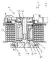
- eine Schnittansicht einer Kabeltrommel,
- Fig. 2
- eine perspektivische Ansicht der Kabeltrommel gemäß Fig. 1,
- Fig. 3, 4
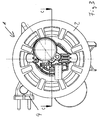
- Seitenansichten der Kabeltrommel gemäß Fig. 1 und
- Fig. 5 - 7
- schematische Schnittansichten von Kabeltrommeln.
- Eine Kabeltrommel 1 (Fig. 1 bis 4) weist einen Trommelkörper 2 zur Aufnahme eines Kabels 3 auf, das mehrlagig auf den Trommelkörper 2 aufgewickelt ist und an dessen ausgangsseitigem Ende ein Stecker 4 angebracht ist. Der Trommelkörper 2 ist über eine seine Drehachse bildende Grundplatte 5 gelagert und dreht sich um diese.
- Eine Halteplatte 6 ist fest mit dem Trommelkörper 2 verbunden. An der Halteplatte 6 ist ein Bremszapfen 7 (Fig. 2) angebracht, der durch die von ihm in einer Bremskulisse 8 ausgeübte Gleitreibung den Trommelkörper 2 abbremst, der durch seine Drehbewegung einen Bremsimpuls auf die Bremskulisse 8 überträgt. Die Bremskulisse 8 ist über elastische Elemente 9, 10 in einem die Kabeltrommel aufnehmenden Körper, beispielsweise ein Staubsaugergehäuse, gelagert.
- Die Bremskulisse 8 weist vorzugsweise nach außen weisende Vorsprünge 11, 12 auf, auf die die Elemente 9, 10 aufgeschoben sind.
- Die Grundplatte 5 ist derart mit der Bremskulisse 8 gekoppelt, dass zwar einerseits eine Übertragung des von Bremsimpulses der Bremskulisse 8 auf die elastischen Elemente 9, 10 möglich ist, andererseits jedoch eine feste Verbindung zwischen der Grundplatte 5 und der Bremskulisse 8 in axialer Richtung gewährleistet ist.
- In einem weiteren Ausführungsbeispiel (Fig. 5) ist die Lagerung der Bremskulisse 8 über die Elemente 9, 10 in einem Gehäuse 13 schematisch dargestellt.
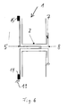
- In einem anderen Ausführungsbeispiel (Fig. 6) sind anstelle des Einsatzes der Elemente 9, 10 mit der Grundplatte 5 verbundene elastische Elemente 14, 15 vorgesehen, die die Grundplatte 5 in dem Gehäuse 13 elastisch lagern und dadurch eine Dissipation des Bremsimpulses ermöglichen.
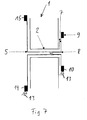
- In einem anderen Ausführungsbeispiel (Fig. 7) sind sowohl die Elemente 9, 10 als auch die Elemente 14, 15 vorgesehen, um die Kabeltrommel 1 in dem Gehäuse 13 elastisch zu lagern.
- Gemäß der Erfindung wird eine Kabeltrommel 1 geschaffen, bei der durch den Einsatz elastischer Elemente 9, 10; 14, 15 zur Lagerung der Kabeltrommel 1 in einem Gehäuse 13 eine Ableitung des Bremsimpulses auf das Gehäuse 13 möglich ist, so dass sich die Bremsenergie in Wärme umwandelt. Die erfindungsgemäße Kabeltrommel 1 ist insbesondere auch für solche Trommelkörper 2 geeignet, die große Kabellängen aufnehmen.
Claims (4)
- Kabeltrommel (1), insbesondere für einen Staubsauger, mit einem Trommelkörper (2) und einer Grundplatte (5), gegenüber der der Trommelkörper (2) drehbar gelagert ist, und einer Bremskulisse (8), dadurch gekennzeichnet, dass die Bremskulisse (8) gegenüber der Grundplatte in radialer Richtung beweglich ist und dass elastische Elemente (9,10;14, 15) vorhanden sind, durch die die Kabeltrommel (1) in einem sie aufnehmenden Körper (13), insbesondere in dem Staubsauger, lagerbar ist.
- Kabeltrommel nach Anspruch 1, dadurch gekennzeichnet, dass die elastischen Elemente (9,10) zwischen der Bremskulisse (8) und dem Körper (13) angeordnet sind.
- Kabeltrommel nach Anspruch 1, dadurch gekennzeichnet, dass die elastischen Elemente (14, 15) zwischen der Grundplatte (5) und dem Körper (13) angeordnet sind.
- Kabeltrommel nach einem der Ansprüche 1 bis 3, dadurch gekennzeichnet, dass die Kabeltrommel (1) als ganze über elastische Elemente (9, 10; 14, 15) in dem Körper (13) gelagert ist.
Applications Claiming Priority (3)
| Application Number | Priority Date | Filing Date | Title |
|---|---|---|---|
| DE10142110A DE10142110A1 (de) | 2001-08-30 | 2001-08-30 | Kabeltrommel |
| DE10142110 | 2001-08-30 | ||
| PCT/EP2002/009514 WO2003020099A2 (de) | 2001-08-30 | 2002-08-26 | Kabeltrommel |
Publications (2)
| Publication Number | Publication Date |
|---|---|
| EP1423041A2 EP1423041A2 (de) | 2004-06-02 |
| EP1423041B1 true EP1423041B1 (de) | 2007-10-24 |
Family
ID=7696853
Family Applications (1)
| Application Number | Title | Priority Date | Filing Date |
|---|---|---|---|
| EP02772208A Expired - Lifetime EP1423041B1 (de) | 2001-08-30 | 2002-08-26 | Kabeltrommel |
Country Status (11)
| Country | Link |
|---|---|
| US (1) | US6942078B2 (de) |
| EP (1) | EP1423041B1 (de) |
| KR (1) | KR100576891B1 (de) |
| CN (1) | CN100401970C (de) |
| AT (1) | ATE376382T1 (de) |
| DE (2) | DE10142110A1 (de) |
| HU (1) | HUP0401430A2 (de) |
| MX (1) | MXPA04001842A (de) |
| PL (1) | PL200258B1 (de) |
| RU (1) | RU2264158C2 (de) |
| WO (1) | WO2003020099A2 (de) |
Families Citing this family (7)
| Publication number | Priority date | Publication date | Assignee | Title |
|---|---|---|---|---|
| DE102004040984A1 (de) | 2004-08-24 | 2006-03-02 | BSH Bosch und Siemens Hausgeräte GmbH | Kabeltrommel mit einem ungelagerten Trommelflansch, der ein Anschlagmittel aufweist |
| CN201639136U (zh) * | 2009-12-29 | 2010-11-17 | 三一重型装备有限公司 | 一种隔爆电缆卷筒 |
| DE202010013009U1 (de) | 2010-11-29 | 2011-04-07 | Brunn, Hans-Jürgen | Mehrfachsteckvorrichtung |
| CN102556776B (zh) * | 2010-12-17 | 2015-01-14 | 太仓阿托斯电气部件有限公司 | 卷线器的刹车结构 |
| CN102910499B (zh) * | 2012-10-30 | 2015-11-04 | 中北大学 | 闭合式双路收放装置 |
| US9943071B2 (en) * | 2016-04-19 | 2018-04-17 | Kevin A Hill | Length control system and method |
| US10893660B2 (en) | 2016-04-19 | 2021-01-19 | Kevin A. Hill | Length control system and method |
Family Cites Families (19)
| Publication number | Priority date | Publication date | Assignee | Title |
|---|---|---|---|---|
| DE381324C (de) * | 1921-05-31 | 1923-09-18 | Anselm Cyran | Biegsame Handnaehnadel |
| DE3115740A1 (de) * | 1981-04-18 | 1982-11-04 | Daimler-Benz Ag, 7000 Stuttgart | "nach dem prinzip des waermerohres kuehlbare bremsscheibe" |
| US4437624A (en) * | 1982-02-01 | 1984-03-20 | Aero-Motive Mfg. Co. | Positioning reel |
| US4483330A (en) * | 1982-07-22 | 1984-11-20 | Motion Control, Inc. | Constant tension traction device |
| US4588226A (en) * | 1983-12-23 | 1986-05-13 | Erda, Inc. | Adjustable chair for aircraft and the like |
| US4830308A (en) * | 1984-07-25 | 1989-05-16 | Brunswick Corporation | Multiple cam mag brake adjustment for bait cast reel |
| US4565011A (en) * | 1984-07-30 | 1986-01-21 | Kim Karger | Automatically retractable chalk line assembly |
| DE3813824A1 (de) * | 1988-04-23 | 1989-11-02 | Miele & Cie | Gleichlaufbremse, insbesondere fuer eine einbau-kabeltrommel eines staubsaugers |
| JPH02100467U (de) * | 1989-01-30 | 1990-08-09 | ||
| DE19505926A1 (de) * | 1995-02-21 | 1996-08-22 | Holzschuh Gmbh & Co Kg | Kabeltrommel |
| DE19607146A1 (de) * | 1996-02-26 | 1997-08-28 | Bosch Siemens Hausgeraete | Bremsanordnung für eine in einem Gehäuse eingebaute selbstaufwickelnde Kabeltrommel |
| US5701981A (en) * | 1996-03-13 | 1997-12-30 | Marshall; Trevor | Retractable power cord |
| CN2269181Y (zh) * | 1996-09-24 | 1997-12-03 | 黄荣华 | 一种新型的吸尘器卷线盘 |
| JPH10297836A (ja) * | 1997-04-28 | 1998-11-10 | Sony Corp | 電気コード収納器 |
| DE19826661C1 (de) * | 1998-06-16 | 1999-10-21 | Atlanta Kabel Steinmueller Gmb | Selbstaufwickelnder Kabelaufroller |
| DE19961115C1 (de) * | 1999-12-17 | 2001-04-19 | Bsh Bosch Siemens Hausgeraete | Kabelaufwickelvorrichtung |
| US6349808B1 (en) * | 2000-03-24 | 2002-02-26 | Multicraft International | Cord rewinder device and horizontally-mounted electrical cord rewinder device for a vacuum cleaner |
| DE10019459C1 (de) * | 2000-04-19 | 2001-12-20 | Lothar Mueller | Kabeltrommel mit ausziehbaren Kabelabschnitten |
| JP2002095233A (ja) * | 2000-09-13 | 2002-03-29 | Isuzu Motors Ltd | 渦電流減速装置 |
-
2001
- 2001-08-30 DE DE10142110A patent/DE10142110A1/de not_active Withdrawn
-
2002
- 2002-08-26 RU RU2004105935/12A patent/RU2264158C2/ru not_active IP Right Cessation
- 2002-08-26 KR KR1020047002803A patent/KR100576891B1/ko not_active Expired - Fee Related
- 2002-08-26 CN CNB028170938A patent/CN100401970C/zh not_active Expired - Fee Related
- 2002-08-26 WO PCT/EP2002/009514 patent/WO2003020099A2/de not_active Ceased
- 2002-08-26 HU HU0401430A patent/HUP0401430A2/hu unknown
- 2002-08-26 AT AT02772208T patent/ATE376382T1/de not_active IP Right Cessation
- 2002-08-26 PL PL366850A patent/PL200258B1/pl not_active IP Right Cessation
- 2002-08-26 EP EP02772208A patent/EP1423041B1/de not_active Expired - Lifetime
- 2002-08-26 DE DE50211120T patent/DE50211120D1/de not_active Expired - Lifetime
- 2002-08-26 MX MXPA04001842A patent/MXPA04001842A/es unknown
-
2004
- 2004-03-01 US US10/791,594 patent/US6942078B2/en not_active Expired - Fee Related
Also Published As
| Publication number | Publication date |
|---|---|
| DE10142110A1 (de) | 2003-03-20 |
| PL366850A1 (en) | 2005-02-07 |
| CN1549688A (zh) | 2004-11-24 |
| KR20040029043A (ko) | 2004-04-03 |
| DE50211120D1 (de) | 2007-12-06 |
| MXPA04001842A (es) | 2004-06-15 |
| ATE376382T1 (de) | 2007-11-15 |
| RU2004105935A (ru) | 2005-02-27 |
| HUP0401430A2 (en) | 2008-04-28 |
| EP1423041A2 (de) | 2004-06-02 |
| CN100401970C (zh) | 2008-07-16 |
| US6942078B2 (en) | 2005-09-13 |
| PL200258B1 (pl) | 2008-12-31 |
| RU2264158C2 (ru) | 2005-11-20 |
| US20040168872A1 (en) | 2004-09-02 |
| KR100576891B1 (ko) | 2006-05-03 |
| WO2003020099A2 (de) | 2003-03-13 |
| WO2003020099A3 (de) | 2003-10-16 |
Similar Documents
| Publication | Publication Date | Title |
|---|---|---|
| DE112006000733T5 (de) | Signalübertragungskabel mit Audioschnittstelle und USB-Schnittstelle | |
| DE3810012A1 (de) | Bremsscheiben-bausatz | |
| DE102014118429A1 (de) | Lenkvorrichtung zur Verwendung in einer Solarnachführungsanlage | |
| WO2009118070A1 (de) | Elektrowerkzeugmaschine | |
| DE2949093C2 (de) | Kabelhaspel | |
| DE29914341U1 (de) | Drehknopf-Schalteinrichtung | |
| DE1208971B (de) | Kabelhaspel-Bremseinrichtung | |
| WO2003020099A2 (de) | Kabeltrommel | |
| DE19505926A1 (de) | Kabeltrommel | |
| DE2613944A1 (de) | Rohrreinigungsgeraet mit einer in umdrehung versetzbaren drahtwendel, die mit einem antrieb kuppelbar ist | |
| CN110543216A (zh) | 一种计算机用便于排线维护的机箱 | |
| DE202014105982U1 (de) | Lenkvorrichtung zur Verwendung in einer Solarnachführungsanlage | |
| DE102011116818A1 (de) | Löseeinheit zur Betätigung eines Spannmechanismus | |
| DE4026782C2 (de) | Vorrichtung zum Speichern von dünnem elastischem Material | |
| DE1488672C3 (de) | Elektrischer Kupplungsmotor mit Bremse | |
| DE112010005799T5 (de) | Elektrohandwerkzeug mit Schnellbremsanordnung | |
| DE2610916C3 (de) | Kabeltrommel mit entriegelbarer Sperre zum selbsttätigen Aufwickeln einer elektrischen Leitung | |
| DE102009058982A1 (de) | Vorrichtung zum Setzen von Befestigungselementen | |
| CH248096A (de) | Kabelaufrollvorrichtung. | |
| DE1615044A1 (de) | Motorantrieb fuer Schalter,insbesondere fuer elektrische Selbstschalter | |
| DE2849035A1 (de) | Zahnaerztliches behandlungsgeraet | |
| DE29906919U1 (de) | Kabelspuler mit stehender Wickelachse | |
| DE102017126772A1 (de) | Vorrichtung zur höhenverstellbaren Befestigung einer Leuchte an einer Decke | |
| DE3528745A1 (de) | Kabelbox fuer netzkabel von elektrogeraeten | |
| DE3107831A1 (de) | Wickelvorrichtung zur herstellung elektrisch leitender verbindungen bei einem mit einem isolierten draht umwickelten stift (wrapping post) |
Legal Events
| Date | Code | Title | Description |
|---|---|---|---|
| PUAI | Public reference made under article 153(3) epc to a published international application that has entered the european phase |
Free format text: ORIGINAL CODE: 0009012 |
|
| AK | Designated contracting states |
Kind code of ref document: A2 Designated state(s): AT BE BG CH CY CZ DE DK EE ES FI FR GB GR IE IT LI LU MC NL PT SE SK TR |
|
| AX | Request for extension of the european patent |
Extension state: AL LT LV MK RO SI |
|
| 17P | Request for examination filed |
Effective date: 20040416 |
|
| RIN1 | Information on inventor provided before grant (corrected) |
Inventor name: KOMESKER, HEINRICH Inventor name: HAMM, SILVIO Inventor name: PRELL, MANFRED |
|
| GRAP | Despatch of communication of intention to grant a patent |
Free format text: ORIGINAL CODE: EPIDOSNIGR1 |
|
| GRAS | Grant fee paid |
Free format text: ORIGINAL CODE: EPIDOSNIGR3 |
|
| GRAA | (expected) grant |
Free format text: ORIGINAL CODE: 0009210 |
|
| AK | Designated contracting states |
Kind code of ref document: B1 Designated state(s): AT BE BG CH CY CZ DE DK EE ES FI FR GB GR IE IT LI LU MC NL PT SE SK TR |
|
| REG | Reference to a national code |
Ref country code: GB Ref legal event code: FG4D Free format text: NOT ENGLISH |
|
| REG | Reference to a national code |
Ref country code: CH Ref legal event code: EP |
|
| REG | Reference to a national code |
Ref country code: IE Ref legal event code: FG4D Free format text: LANGUAGE OF EP DOCUMENT: GERMAN |
|
| REF | Corresponds to: |
Ref document number: 50211120 Country of ref document: DE Date of ref document: 20071206 Kind code of ref document: P |
|
| NLV1 | Nl: lapsed or annulled due to failure to fulfill the requirements of art. 29p and 29m of the patents act | ||
| PG25 | Lapsed in a contracting state [announced via postgrant information from national office to epo] |
Ref country code: ES Free format text: LAPSE BECAUSE OF FAILURE TO SUBMIT A TRANSLATION OF THE DESCRIPTION OR TO PAY THE FEE WITHIN THE PRESCRIBED TIME-LIMIT Effective date: 20080204 Ref country code: NL Free format text: LAPSE BECAUSE OF FAILURE TO SUBMIT A TRANSLATION OF THE DESCRIPTION OR TO PAY THE FEE WITHIN THE PRESCRIBED TIME-LIMIT Effective date: 20071024 Ref country code: SE Free format text: LAPSE BECAUSE OF FAILURE TO SUBMIT A TRANSLATION OF THE DESCRIPTION OR TO PAY THE FEE WITHIN THE PRESCRIBED TIME-LIMIT Effective date: 20080124 |
|
| GBV | Gb: ep patent (uk) treated as always having been void in accordance with gb section 77(7)/1977 [no translation filed] | ||
| PG25 | Lapsed in a contracting state [announced via postgrant information from national office to epo] |
Ref country code: PT Free format text: LAPSE BECAUSE OF FAILURE TO SUBMIT A TRANSLATION OF THE DESCRIPTION OR TO PAY THE FEE WITHIN THE PRESCRIBED TIME-LIMIT Effective date: 20080324 Ref country code: BG Free format text: LAPSE BECAUSE OF FAILURE TO SUBMIT A TRANSLATION OF THE DESCRIPTION OR TO PAY THE FEE WITHIN THE PRESCRIBED TIME-LIMIT Effective date: 20080124 |
|
| REG | Reference to a national code |
Ref country code: IE Ref legal event code: FD4D |
|
| PG25 | Lapsed in a contracting state [announced via postgrant information from national office to epo] |
Ref country code: DK Free format text: LAPSE BECAUSE OF FAILURE TO SUBMIT A TRANSLATION OF THE DESCRIPTION OR TO PAY THE FEE WITHIN THE PRESCRIBED TIME-LIMIT Effective date: 20071024 Ref country code: CZ Free format text: LAPSE BECAUSE OF FAILURE TO SUBMIT A TRANSLATION OF THE DESCRIPTION OR TO PAY THE FEE WITHIN THE PRESCRIBED TIME-LIMIT Effective date: 20071024 |
|
| EN | Fr: translation not filed | ||
| PG25 | Lapsed in a contracting state [announced via postgrant information from national office to epo] |
Ref country code: SK Free format text: LAPSE BECAUSE OF FAILURE TO SUBMIT A TRANSLATION OF THE DESCRIPTION OR TO PAY THE FEE WITHIN THE PRESCRIBED TIME-LIMIT Effective date: 20071024 |
|
| PLBE | No opposition filed within time limit |
Free format text: ORIGINAL CODE: 0009261 |
|
| STAA | Information on the status of an ep patent application or granted ep patent |
Free format text: STATUS: NO OPPOSITION FILED WITHIN TIME LIMIT |
|
| 26N | No opposition filed |
Effective date: 20080725 |
|
| PG25 | Lapsed in a contracting state [announced via postgrant information from national office to epo] |
Ref country code: IE Free format text: LAPSE BECAUSE OF FAILURE TO SUBMIT A TRANSLATION OF THE DESCRIPTION OR TO PAY THE FEE WITHIN THE PRESCRIBED TIME-LIMIT Effective date: 20071024 Ref country code: FR Free format text: LAPSE BECAUSE OF FAILURE TO SUBMIT A TRANSLATION OF THE DESCRIPTION OR TO PAY THE FEE WITHIN THE PRESCRIBED TIME-LIMIT Effective date: 20080808 |
|
| PG25 | Lapsed in a contracting state [announced via postgrant information from national office to epo] |
Ref country code: GB Free format text: LAPSE BECAUSE OF FAILURE TO SUBMIT A TRANSLATION OF THE DESCRIPTION OR TO PAY THE FEE WITHIN THE PRESCRIBED TIME-LIMIT Effective date: 20071024 |
|
| PG25 | Lapsed in a contracting state [announced via postgrant information from national office to epo] |
Ref country code: GR Free format text: LAPSE BECAUSE OF FAILURE TO SUBMIT A TRANSLATION OF THE DESCRIPTION OR TO PAY THE FEE WITHIN THE PRESCRIBED TIME-LIMIT Effective date: 20080125 |
|
| PG25 | Lapsed in a contracting state [announced via postgrant information from national office to epo] |
Ref country code: FI Free format text: LAPSE BECAUSE OF FAILURE TO SUBMIT A TRANSLATION OF THE DESCRIPTION OR TO PAY THE FEE WITHIN THE PRESCRIBED TIME-LIMIT Effective date: 20071024 |
|
| PG25 | Lapsed in a contracting state [announced via postgrant information from national office to epo] |
Ref country code: MC Free format text: LAPSE BECAUSE OF NON-PAYMENT OF DUE FEES Effective date: 20080831 |
|
| REG | Reference to a national code |
Ref country code: CH Ref legal event code: PL |
|
| PG25 | Lapsed in a contracting state [announced via postgrant information from national office to epo] |
Ref country code: EE Free format text: LAPSE BECAUSE OF FAILURE TO SUBMIT A TRANSLATION OF THE DESCRIPTION OR TO PAY THE FEE WITHIN THE PRESCRIBED TIME-LIMIT Effective date: 20071024 |
|
| PG25 | Lapsed in a contracting state [announced via postgrant information from national office to epo] |
Ref country code: LI Free format text: LAPSE BECAUSE OF NON-PAYMENT OF DUE FEES Effective date: 20080831 Ref country code: CH Free format text: LAPSE BECAUSE OF NON-PAYMENT OF DUE FEES Effective date: 20080831 |
|
| PG25 | Lapsed in a contracting state [announced via postgrant information from national office to epo] |
Ref country code: BE Free format text: LAPSE BECAUSE OF NON-PAYMENT OF DUE FEES Effective date: 20080831 Ref country code: CY Free format text: LAPSE BECAUSE OF FAILURE TO SUBMIT A TRANSLATION OF THE DESCRIPTION OR TO PAY THE FEE WITHIN THE PRESCRIBED TIME-LIMIT Effective date: 20071024 |
|
| PG25 | Lapsed in a contracting state [announced via postgrant information from national office to epo] |
Ref country code: AT Free format text: LAPSE BECAUSE OF NON-PAYMENT OF DUE FEES Effective date: 20080826 |
|
| PG25 | Lapsed in a contracting state [announced via postgrant information from national office to epo] |
Ref country code: LU Free format text: LAPSE BECAUSE OF NON-PAYMENT OF DUE FEES Effective date: 20080826 |
|
| PG25 | Lapsed in a contracting state [announced via postgrant information from national office to epo] |
Ref country code: TR Free format text: LAPSE BECAUSE OF FAILURE TO SUBMIT A TRANSLATION OF THE DESCRIPTION OR TO PAY THE FEE WITHIN THE PRESCRIBED TIME-LIMIT Effective date: 20071024 |
|
| PG25 | Lapsed in a contracting state [announced via postgrant information from national office to epo] |
Ref country code: IT Free format text: LAPSE BECAUSE OF NON-PAYMENT OF DUE FEES Effective date: 20080831 |
|
| PGFP | Annual fee paid to national office [announced via postgrant information from national office to epo] |
Ref country code: DE Payment date: 20120831 Year of fee payment: 11 |
|
| PG25 | Lapsed in a contracting state [announced via postgrant information from national office to epo] |
Ref country code: DE Free format text: LAPSE BECAUSE OF NON-PAYMENT OF DUE FEES Effective date: 20140301 |
|
| REG | Reference to a national code |
Ref country code: DE Ref legal event code: R119 Ref document number: 50211120 Country of ref document: DE Effective date: 20140301 |