EP1422472A2 - Projecteur elliptique pour véhicule automobile émettant des faisceaux d'éclairage différents - Google Patents
Projecteur elliptique pour véhicule automobile émettant des faisceaux d'éclairage différents Download PDFInfo
- Publication number
- EP1422472A2 EP1422472A2 EP03292836A EP03292836A EP1422472A2 EP 1422472 A2 EP1422472 A2 EP 1422472A2 EP 03292836 A EP03292836 A EP 03292836A EP 03292836 A EP03292836 A EP 03292836A EP 1422472 A2 EP1422472 A2 EP 1422472A2
- Authority
- EP
- European Patent Office
- Prior art keywords
- cover
- projector
- spring
- projector according
- reflector
- Prior art date
- Legal status (The legal status is an assumption and is not a legal conclusion. Google has not performed a legal analysis and makes no representation as to the accuracy of the status listed.)
- Withdrawn
Links
Images


Classifications
-
- F—MECHANICAL ENGINEERING; LIGHTING; HEATING; WEAPONS; BLASTING
- F21—LIGHTING
- F21S—NON-PORTABLE LIGHTING DEVICES; SYSTEMS THEREOF; VEHICLE LIGHTING DEVICES SPECIALLY ADAPTED FOR VEHICLE EXTERIORS
- F21S41/00—Illuminating devices specially adapted for vehicle exteriors, e.g. headlamps
- F21S41/60—Illuminating devices specially adapted for vehicle exteriors, e.g. headlamps characterised by a variable light distribution
- F21S41/68—Illuminating devices specially adapted for vehicle exteriors, e.g. headlamps characterised by a variable light distribution by acting on screens
- F21S41/683—Illuminating devices specially adapted for vehicle exteriors, e.g. headlamps characterised by a variable light distribution by acting on screens by moving screens
- F21S41/689—Flaps, i.e. screens pivoting around one of their edges
-
- F—MECHANICAL ENGINEERING; LIGHTING; HEATING; WEAPONS; BLASTING
- F21—LIGHTING
- F21S—NON-PORTABLE LIGHTING DEVICES; SYSTEMS THEREOF; VEHICLE LIGHTING DEVICES SPECIALLY ADAPTED FOR VEHICLE EXTERIORS
- F21S41/00—Illuminating devices specially adapted for vehicle exteriors, e.g. headlamps
- F21S41/10—Illuminating devices specially adapted for vehicle exteriors, e.g. headlamps characterised by the light source
- F21S41/14—Illuminating devices specially adapted for vehicle exteriors, e.g. headlamps characterised by the light source characterised by the type of light source
- F21S41/162—Incandescent light sources, e.g. filament or halogen lamps
- F21S41/168—Incandescent light sources, e.g. filament or halogen lamps having a filament arranged transversally to the optical axis of the illuminating device
-
- F—MECHANICAL ENGINEERING; LIGHTING; HEATING; WEAPONS; BLASTING
- F21—LIGHTING
- F21S—NON-PORTABLE LIGHTING DEVICES; SYSTEMS THEREOF; VEHICLE LIGHTING DEVICES SPECIALLY ADAPTED FOR VEHICLE EXTERIORS
- F21S41/00—Illuminating devices specially adapted for vehicle exteriors, e.g. headlamps
- F21S41/20—Illuminating devices specially adapted for vehicle exteriors, e.g. headlamps characterised by refractors, transparent cover plates, light guides or filters
- F21S41/25—Projection lenses
- F21S41/255—Lenses with a front view of circular or truncated circular outline
-
- F—MECHANICAL ENGINEERING; LIGHTING; HEATING; WEAPONS; BLASTING
- F21—LIGHTING
- F21S—NON-PORTABLE LIGHTING DEVICES; SYSTEMS THEREOF; VEHICLE LIGHTING DEVICES SPECIALLY ADAPTED FOR VEHICLE EXTERIORS
- F21S41/00—Illuminating devices specially adapted for vehicle exteriors, e.g. headlamps
- F21S41/30—Illuminating devices specially adapted for vehicle exteriors, e.g. headlamps characterised by reflectors
- F21S41/32—Optical layout thereof
- F21S41/321—Optical layout thereof the reflector being a surface of revolution or a planar surface, e.g. truncated
-
- F—MECHANICAL ENGINEERING; LIGHTING; HEATING; WEAPONS; BLASTING
- F21—LIGHTING
- F21S—NON-PORTABLE LIGHTING DEVICES; SYSTEMS THEREOF; VEHICLE LIGHTING DEVICES SPECIALLY ADAPTED FOR VEHICLE EXTERIORS
- F21S45/00—Arrangements within vehicle lighting devices specially adapted for vehicle exteriors, for purposes other than emission or distribution of light
- F21S45/40—Cooling of lighting devices
- F21S45/47—Passive cooling, e.g. using fins, thermal conductive elements or openings
Definitions
- the present invention relates to projectors of the elliptical type. for motor vehicles.
- Elliptical type headlamps comprise in known manner a light source, an elliptical type reflector including a first focus is located near the source, a converging lens whose a focal plane passes in the vicinity of a second focus of the reflector.
- Such a headlamp When such a headlamp must form a cut-off beam, such than a passing beam or a fog beam, it includes a cover interposed at the second focal point of the reflector, which obscures the part of the radiation, which would otherwise spread over this cut.
- a known solution to modify the profile of the cut consists to intervene on the projector cover to modify its profile cut.
- a elliptical projector of the type comprising a first cover provided between the reflector and lens, which has an edge defining a first profile particular cut-off for the light beam emitted, and a second cover disposed on the first cover and selectively movable between two positions, a first position in which an edge of the second cover is positioned on the path of the light rays to form with the first hides a light beam with a second cut profile particular, and a second position in which said edge of the second cover is substantially positioned outside the path of the light rays to form a light beam with the first cut profile.
- a solution to selectively perform a function crossing or a road function consists of rotating the cover mobile of the projector to position it respectively in or out of the light beam emitted.
- the cover is pivotally mounted on a frame part of the projector, at one of its lateral sides, and the movement of the cover is pivoted so that it always remains in the vertical plane transverse to the optical axis where it is in position crossing.
- Such a projector has several drawbacks. First of all, with such a cover arrangement pivoting about an axis parallel to the optical axis, taking into account the small space available in the housing of the projector, below the cover, it is impossible to release completely cover the emitted light beam, on the side of the axis of pivoting of said cover.
- document FR-A-2,796,449 offers an elliptical type projector which has a main cover mounted pivoting about a transverse axis and which includes a cover secondary mounted pivoting about an axis parallel to the optical axis.
- the spotlight creates a beam lighting with a first cut-off profile.
- the projector achieves a lighting beam with a second cutoff profile different from the first.
- the secondary cover is provided to modify the cut made by the main cover in the lighting beam by increasing the obscured surface. Therefore, the secondary cache does not allow create a light beam with a cut-off profile specific with a less obscured lighting area compared to at the first cut profile.
- the secondary cover being of small dimensions, the thermal stresses to which it is subjected inside the projector may change its geometry and cause projector malfunctions.
- the thermal constraints mentioned above also make it difficult to index the different positions of the secondary cover.
- the route function is difficult to achieve in because of the proximity of the pivot axis of the secondary cover with the upper part of the main cover, this proximity being imposed by the optical conjugation of the lens with the reflector.
- the present invention is placed in this context and aims to remedy these drawbacks by proposing a projector equipped with movable covers so as to generate different beams lighting, which is simple, reliable and economical.
- the invention provides a vehicle headlamp automobile, comprising a light source, a reflector of the type elliptical whose first focus is located near the source, a converging lens of which a focal plane passes in the vicinity of a second reflector focus, first and second covers which are inserted axially, along the optical axis of the projector, between the reflector and the lens, of the type in which the first cover is pivotally mounted around of a substantially transverse axis between two extreme positions.
- the second cover is pivotally mounted around the same pivot axis, the second cover being mounted free to rotate around the pivot axis and being subjected only to the action of a spring and a locking element.
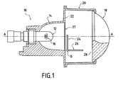
- a headlight 10 for a vehicle is shown.
- automobile which comprises a lamp 12 mounted in the bottom of a reflector 14 of the elliptical type such that the light source 16, ie the filament of an incandescent lamp as on the Figure 1 or the electric arc of a discharge lamp as in the other Figures, is located in the vicinity of a first focus of the reflector 14.
- orientation from back to front along the optical axis A-A of the projector 10, which corresponds to an orientation from left to right considering the Figure 1, i.e. in the direction of propagation of the light rays at the projector output.
- the optical axis A-A is generally parallel to the longitudinal axis of the vehicle that the headlight 10 equips.
- the optical axis A-A is here substantially horizontal and it can be defined for example by the two focal points of the reflector 14.
- the projector 10 includes a converging lens 18, for example example plano-convex, which is mounted, in the front, in a part intermediate 20 of the projector 10 fixed on a transverse surface front 22 of reflector 14.
- a converging lens 18, for example example plano-convex which is mounted, in the front, in a part intermediate 20 of the projector 10 fixed on a transverse surface front 22 of reflector 14.
- the focal plane of the lens 18 passes in the vicinity of the second focal point of the reflector 14.
- the projector 10 has a first cover 24 and a second cover 26 which are interposed between the reflector 14 and the lens 18, at the vicinity of the focal plane of the lens 18.
- All the elements described above constitute a block spotlight optics 10 which is for example mounted so classic in a case (not shown) closed by a glass.
- first cover 24 and the second cover 26 are pivotally mounted with respect to to the reflector 14, around a same transverse geometric axis B-B, between a retracted position Pe and a concealing position Po.
- the covers 24, 26 are for example pivotally mounted on a intermediate support plate 27 which is axially interposed between the reflector 14 and the framework part 20.
- FIGS 2 and 3 show in a simplified manner the projector 10 of Figure 1. In this Figure therefore appear a portion of the reflector 14 and the two covers 24, 26. There is shown also, in broken lines, the rear transverse face 28 of the lens 18.
- the cover actuator 24 is also shown, here in the form of an electric motor 30.
- control actuators could be used, for example electromagnet actuators such as those used for the pivoting of the covers in document FR-A-2,796,449 to which may refer for further details.
- each cover 24, 26 has overall the shape of a rectangular plate which, in the position occultation Po, extends in a transverse and vertical plane, and which, in the retracted position Pe, extends in a plane substantially horizontal.
- the rectangular plates forming the covers 24, 26 have large dimensions which favors their capacity heat dissipation and which allows them to be insensitive to thermal stresses inside the projector 10.
- the first cover 24 is plate-shaped and has two edges 34, 36 substantially transverse and two lateral edges 38, 40 substantially vertical which give the plate a shape overall rectangular.
- the geometric pivot axis B-B of the first cover 24 is arranged here along the lower transverse edge, or transverse edge of pivot 34.
- the first cover 24 comprises at each end of the transverse pivot edge a section shaft 42, 44 which, on one side, is mounted to rotate freely in a bearing 43 and on the other side is integral with rotation of the drive shaft of actuator 30.
- the transverse edge 36 opposite the transverse pivoting edge 34 forms the cutting edge of the cover 24, i.e. it delimits a cut-off profile for the light beam emitted by the projector 10 when the cover 24 occupies its concealed position Po.
- the cutting edge 36 of the first cover 24 is for example designed to perform a low beam lighting function. he therefore comprises two horizontal portions 44, 46 vertically offset, in the masking position Po, and connected by an inclined portion 48 so that the spotlight 10 achieves a regulatory beam of fire of crossing for a given traffic direction.
- the second cover 26 is similar to the first cover 24 and is shown in its position retracted Pe in FIGS. 1 and 2, and in the concealed position Po on Figure 3.
- the second cover 26 is also in the form of a plate and it has two substantially transverse edges and two lateral edges substantially vertical which give the plate a shape overall rectangular.
- the second cover 26 is mounted free to rotate about the axis B-B.
- the projector 10 is thus capable of emitting a beam of road when the two covers 24 and 26 are in the retracted position Pe, a passing beam for a given traffic direction when only the first cover is in Po concealment position, and another cut-off beam when the two covers 24 and 26 are in position occultation.
- This other passing beam can be adapted to the other direction circulation, or the cutting edges 36, 56 of the two covers 24, 26 can be provided so that, when the two covers 24, 26 occupy their occulting position Po, the overlapping of the covers 24, 26 according to the optical axis A-A makes it possible to perform an “AFS” lighting function additional.
- this lighting function must include a beam of lighting with a larger obscured portion than in each of the lighting functions associated with the two covers 24, 26, since the light beam associated with this lighting function additional will be obscured by both the first 24 and the second 26 caches.
- This additional lighting function is for example a rain function ("Adverse Weather Lighting”) in which the concealment is more important than in lighting in passing beam.
- the cutting edge 56 of the second cover 26 is for example planned to adapt the regulatory beam of low beam generated by the projector 10 when the first cover 24 is in blackout position Po in the other direction of traffic.
- the cutting edge 56 is flat, and, when the second cover 26 is in the obscuring position Po, as we have shown in Figure 3, contained in the horizontal plane containing the cutting edge 46 of the first cover 24.
- the projector 10 when the second cover 26 is in the retracted position Pe, the projector 10 emits a passing beam for a direction of given circulation, and when the second cover 26 is in position occultation, the projector 10 emits a beam allowing circulation in the other direction.
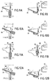
- FIGS. 4A to 7B show a first mode of embodiment of the invention, the figures of index A being side views, and the Figures of index B being sectional views along a vertical plane passing through the axis A-A.
- the second cover 26 is subjected to the action of a spring 60, one end of which is trapped of the intermediate support plate 27, and the other end of which biases the second cover 26 backwards, in its position occultation Po.
- the spring 60 can be produced in the form of a pin, the branches being fixed on the plate 27 and the second cover 26, a spring 60 loop surrounding axis B-B.
- the second cover 26 is also integral with a stud 62, extending parallel to the axis B-B.
- the projector 10 is also equipped a pull tab 64, extending parallel to the axis A-A of the headlight, and likely to occupy by translation in a direction parallel to the axis A-Has two extreme positions, front and rear.
- Zipper 64 carries front end a pallet 66, in which a light is formed, comprising a rectilinear part 68, vertical, and a circular part 70, communicating with the upper end of the straight part 68.
- the pin 62 is capable of sliding in light 68-70.
- the pull tab 64 When the pull tab 64 is in its extreme front position, the stud 62 is received in the rectilinear light 68, at the lower end of it. In this position, the second cover 62 is immobilized in retracted position Pe.
- the first cover 24 is still capable of being moved by the actuator 30, between a position where the projector 10 generates a beam with a first cut, as in Figures 4A and 4B, and a position where it generates a beam of route, as in Figures 5A and 5B.
- the circular part of the light 70 is centered on the axis B of rotation of the two covers 24 and 26.
- the projector 10 can therefore emit a beam with a second break, in the position shown in Figures 6A and 6B, or a main beam, in the position shown in Figures 7A and 7B.
- FIGS. 8 to 12B show a second mode of embodiment of the invention, the figures of index A being side views, and the Figures of index B being sectional views along a vertical plane passing through the axis A-A.
- the second cover 26 here again is subjected to the action of a spring 72, one end of which is trapped in the intermediate support plate 27, and the other of which end urges the second cover 26.
- the spring 72 biases the second cover 26 towards the front, in its retracted position Pe, in abutment on a fixed part of the support plate 27.
- the projector 10 includes a magnet 80, capable of being moved from a rest position R to a working position T. In the rest position R, the magnet 80 is kept apart from the covers 24 and 26, and in the working position T, it is integral with the first cover 24.
- the second cover 26 In its rest position, the second cover 26 is maintained in its retracted position Pe under the action of the spring 72, as has been shown in Figures 8, 9A and 9B, so that the projector 10 can emit a beam with a first cut, or a beam of road, as shown in Figures 10A and 10B.
- the first cover 24 When the movement of the first cover 24 is controlled, it is placed in its retracted position Pe, as shown in Figures 10A and 10B, so that the headlight 10 can emit a driving beam.
- the magnet 80 When the magnet 80 is moved to its working position T, it is secured to the first cover 24, for example by clipping. In this position, when the first cover 24 is controlled in its retracted position Pe, the magnet 80 has the effect of attracting the second cover 26, and make it integral with the first cover 24.
- the first cover 24 When the first cover 24 is ordered to come into its occultation position Po, it then drives with it the second cover 26, the force exerted by the magnet 80 being greater than that which is exerted by the spring 80, as shown in Figures 11A and 11B.
- the projector 10 then emits a beam with a second cut.
- the first cover 24 When the first cover 24 is ordered to come into its retracted position Pe, it then drives with it the second cover 26. the force exerted by the magnet 80 being greater than that which is exerted by the spring 80, as shown in Figures 12A and 12B. The headlight 10 then emits a driving beam, without interruption.
- the present invention is not limited to the embodiments that have been described, but it is likely to receive many modifications that fall within its scope.
- a movable magnet instead of a movable magnet, one could advantageously use a electromagnet, fixed on the first cover. When this electromagnet is not not excited, everything happens as if the magnet 80 was in its position of rest R. On the other hand, when this electromagnet is excited, everything happens as if the magnet 80 was in its working position T.
Landscapes
- Engineering & Computer Science (AREA)
- General Engineering & Computer Science (AREA)
- Non-Portable Lighting Devices Or Systems Thereof (AREA)
Abstract
Description
- le premier cache délimite, lorsqu'il est en position d'occultation, un premier profil de coupure pour le faisceau d'éclairage émis par le projecteur, le second cache délimite avec le premier cache, lorsqu'ils sont en position d'occultation, un second profil de coupure pour le faisceau d'éclairage émis par le projecteur, et, lorsque les deux caches sont en position escamotée, le projecteur émet un faisceau sans coupure.
- le ressort sollicite le second cache vers l'arrière.
- l'élément de verrouillage est mobile entre deux positions extrêmes et il est constitué par une palette comportant une lumière dans laquelle est reçu un téton solidaire du second cache.
- dans une première position extrême de l'élément de verrouillage, le second cache est immobilisé dans une position escamotée, et, dans la deuxième position extrême de l'élément de verrouillage, le second cache est sollicité par le ressort en appui sur le premier cache.
- le ressort sollicite le second cache vers l'avant.
- l'élément de verrouillage est constitué par un moyen de solidarisation du second cache avec le premier cache.
- le moyen de solidarisation est un aimant, déplaçable entre une position de repos dans laquelle le second cache est maintenu en position escamotée par le ressort, et une position de travail dans laquelle il est maintenu par le premier cache et maintient le second cache en contact avec le premier.
- le moyen de solidarisation est un électroaimant fixé sur le premier cache.
- la Figure 1 est une vue schématique en coupe d'un projecteur elliptique réalisé conformément aux enseignements de l'invention ;
- la Figure 2 est une vue schématique en perspective du projecteur de la Figure 1, dans une première configuration ;
- la Figure 3 est une vue similaire à celle de le Figure 2, le projecteur étant dans une deuxième configuration ;
- les Figures 4A, 4B, 5A et 5B représentent diverses positions du projecteur de la Figure 1, lorsqu'il est dans sa première configuration, selon un premier mode de réalisation de l'invention ;
- les Figures 6A, 6B, 7A et 7B représentent diverses positions du projecteur de la Figure 1, lorsqu'il est dans sa deuxième configuration, selon le premier mode de réalisation de l'invention ;
- la Figure 8 est une vue schématique en perspective éclatée du projecteur de la Figure 1, selon un deuxième mode de réalisation ;
- les Figures 9A, 9B, 10A et 10B représentent diverses positions du projecteur de la Figure 8, lorsqu'il est dans sa première configuration, selon le deuxième mode de réalisation de l'invention ;
- les Figures 11A, 11B, 12A et 12B représentent diverses positions du projecteur de la Figure 8, lorsqu'il est dans sa deuxième configuration, selon le deuxième mode de réalisation de l'invention.
Claims (9)
- Projecteur (10) pour véhicule automobile, comprenant une source lumineuse (16), un réflecteur (14) du type elliptique dont un premier foyer est situé au voisinage de la source (16), une lentille convergente (18) dont un plan focal passe au voisinage d'un second foyer du réflecteur (14), un premier (24) et un deuxième (26) caches qui sont intercalés axialement, suivant l'axe optique (A-A) du projecteur (10), entre le réflecteur (14) et la lentille (18), du type dans lequel le premier cache (24) est monté pivotant autour d'un axe (B-B) sensiblement transversal entre deux positions extrêmes, caractérisé en ce que le second cache (26) est monté à pivotement autour du même axe de pivotement (B-B), le second cache (26) étant monté libre à rotation autour de l'axe de pivotement (B-B) et n'étant soumis qu'à l'action d'un ressort (60, 72) et d'un élément de verrouillage (64, 66 ; 80).
- Projecteur selon la revendication 1, caractérisé en ce que le premier cache (24) délimite, lorsqu'il est en position d'occultation (Po), un premier profil de coupure pour le faisceau d'éclairage émis par le projecteur (10), en ce que le second cache (26) délimite avec le premier cache (24), lorsqu'ils sont en position d'occultation (Po), un second profil de coupure pour le faisceau d'éclairage émis par le projecteur (10), et en ce que, lorsque les deux caches sont en position escamotée (Pe), le projecteur (10) émet un faisceau sans coupure.
- Projecteur selon la revendication 1, caractérisé en ce que le ressort (60) sollicite le second cache (26) vers l'arrière.
- Projecteur selon la revendication 1, caractérisé en ce l'élément de verrouillage (64, 66) est mobile entre deux positions extrêmes et il est constitué par une palette (66) comportant une lumière (68, 70) dans laquelle est reçu un téton (62) solidaire du second cache (26).
- Projecteur selon la revendication 1, caractérisé en ce que, dans une première position extrême de l'élément de verrouillage (64, 66), le second cache (26) est immobilisé dans une position escamotée (Pe), et en ce que, dans la deuxième position extrême de l'élément de verrouillage (64, 66), le second cache (26) est sollicité par le ressort en appui sur le premier cache (24).
- Projecteur selon la revendication 1, caractérisé en ce que le ressort (72) sollicite le second cache (26) vers l'avant.
- Projecteur selon la revendication 1, caractérisé en ce que l'élément de verrouillage (80) est constitué par un moyen de solidarisation (80) du second cache (26) avec le premier cache (24).
- Projecteur selon la revendication 7, caractérisé en ce que le moyen de solidarisation (80) est un aimant (80), déplaçable entre une position de repos (R) dans laquelle le second cache est maintenu en position escamotée (Pe) par le ressort (72), et une position de travail (T) dans laquelle il est maintenu par le premier cache (24) et maintient le second cache (26) en contact avec le premier (24).
- Projecteur selon la revendication 1, caractérisé en ce que le moyen de solidarisation (80) est un électroaimant fixé sur le premier cache (24).
Applications Claiming Priority (2)
| Application Number | Priority Date | Filing Date | Title |
|---|---|---|---|
| FR0214776 | 2002-11-21 | ||
| FR0214776A FR2847657B1 (fr) | 2002-11-21 | 2002-11-21 | Projecteur elliptique pour vehicule automobile emettant des faisceaux d'eclairage differents |
Publications (2)
| Publication Number | Publication Date |
|---|---|
| EP1422472A2 true EP1422472A2 (fr) | 2004-05-26 |
| EP1422472A3 EP1422472A3 (fr) | 2007-06-27 |
Family
ID=32187815
Family Applications (1)
| Application Number | Title | Priority Date | Filing Date |
|---|---|---|---|
| EP03292836A Withdrawn EP1422472A3 (fr) | 2002-11-21 | 2003-11-14 | Projecteur elliptique pour véhicule automobile émettant des faisceaux d'éclairage différents |
Country Status (2)
| Country | Link |
|---|---|
| EP (1) | EP1422472A3 (fr) |
| FR (1) | FR2847657B1 (fr) |
Cited By (14)
| Publication number | Priority date | Publication date | Assignee | Title |
|---|---|---|---|---|
| EP1726875A1 (fr) | 2005-05-27 | 2006-11-29 | Valeo Vision | Module optique pour dispositif d'éclairage automobile |
| EP1746340A2 (fr) | 2005-07-21 | 2007-01-24 | Valeo Vision | Module optique pour dispositif d'éclairage automobile |
| FR2898403A1 (fr) | 2006-03-07 | 2007-09-14 | Valeo Vision Sa | Lentille pour module optique de dispositif d'eclairage pour vehicule automobile |
| EP2028414A1 (fr) * | 2007-08-22 | 2009-02-25 | Koito Manufacturing Co., Ltd | Phare de véhicule |
| WO2009040710A2 (fr) * | 2007-09-25 | 2009-04-02 | Philips Intellectual Property & Standards Gmbh | Système d'éclairage pour un véhicule à moteur |
| EP2090821A1 (fr) * | 2008-02-14 | 2009-08-19 | Valeo Vision | Module elliptique pour véhicule automobile |
| US7583451B2 (en) | 2005-03-22 | 2009-09-01 | Valeo Vision | Lens for an optical module of a lighting apparatus for a motor vehicle |
| JP2010040459A (ja) * | 2008-08-07 | 2010-02-18 | Koito Mfg Co Ltd | 車両用前照灯装置 |
| EP2098775A3 (fr) * | 2008-03-05 | 2010-06-09 | Koito Manufacturing Co., Ltd. | Projecteur de véhicule automobile |
| EP2405191A1 (fr) * | 2010-07-08 | 2012-01-11 | Koito Manufacturing Co., Ltd. | Unité électroluminescente et phare de véhicule |
| EP2405190A1 (fr) * | 2010-07-09 | 2012-01-11 | Koito Manufacturing Co., Ltd. | Phare de véhicule |
| EP2339229A3 (fr) * | 2009-12-24 | 2012-09-12 | Koito Manufacturing Co., Ltd | Dispositif projecteur pour véhicule automobile |
| US8459849B2 (en) | 2009-04-24 | 2013-06-11 | Valeo Vision | Optical device for a motor vehicle |
| CN114353014A (zh) * | 2022-01-14 | 2022-04-15 | 浙江友德电子科技有限公司 | 一种方便调节的远近光一体式车灯 |
Citations (7)
| Publication number | Priority date | Publication date | Assignee | Title |
|---|---|---|---|---|
| US5339226A (en) * | 1992-06-03 | 1994-08-16 | Koito Manufacturing Co., Ltd. | Projection head lamp for cars |
| FR2769071A1 (fr) * | 1997-09-26 | 1999-04-02 | Valeo Vision | Projecteur de type elliptique a faisceau variable, notamment pour vehicule automobile |
| EP1026439A1 (fr) * | 1999-02-08 | 2000-08-09 | Automotive Lighting Italia Spa | Projecteur pour véhicules automobiles |
| JP2000306414A (ja) * | 1999-04-16 | 2000-11-02 | Stanley Electric Co Ltd | プロジェクタ型車両用灯具 |
| EP0723108B1 (fr) * | 1995-01-17 | 2001-11-21 | Robert Bosch Gmbh | Projecteur pour véhicules |
| FR2809802A1 (fr) * | 2000-05-31 | 2001-12-07 | Valeo Vision | Projecteur pour vehicule automobile a ecran mobile et organe d'actionnement |
| EP1308669A1 (fr) * | 2001-10-30 | 2003-05-07 | Valeo Vision | Dispositif d'éclairage de type elliptique pour véhicule automobile |
-
2002
- 2002-11-21 FR FR0214776A patent/FR2847657B1/fr not_active Expired - Lifetime
-
2003
- 2003-11-14 EP EP03292836A patent/EP1422472A3/fr not_active Withdrawn
Patent Citations (7)
| Publication number | Priority date | Publication date | Assignee | Title |
|---|---|---|---|---|
| US5339226A (en) * | 1992-06-03 | 1994-08-16 | Koito Manufacturing Co., Ltd. | Projection head lamp for cars |
| EP0723108B1 (fr) * | 1995-01-17 | 2001-11-21 | Robert Bosch Gmbh | Projecteur pour véhicules |
| FR2769071A1 (fr) * | 1997-09-26 | 1999-04-02 | Valeo Vision | Projecteur de type elliptique a faisceau variable, notamment pour vehicule automobile |
| EP1026439A1 (fr) * | 1999-02-08 | 2000-08-09 | Automotive Lighting Italia Spa | Projecteur pour véhicules automobiles |
| JP2000306414A (ja) * | 1999-04-16 | 2000-11-02 | Stanley Electric Co Ltd | プロジェクタ型車両用灯具 |
| FR2809802A1 (fr) * | 2000-05-31 | 2001-12-07 | Valeo Vision | Projecteur pour vehicule automobile a ecran mobile et organe d'actionnement |
| EP1308669A1 (fr) * | 2001-10-30 | 2003-05-07 | Valeo Vision | Dispositif d'éclairage de type elliptique pour véhicule automobile |
Cited By (22)
| Publication number | Priority date | Publication date | Assignee | Title |
|---|---|---|---|---|
| US7583451B2 (en) | 2005-03-22 | 2009-09-01 | Valeo Vision | Lens for an optical module of a lighting apparatus for a motor vehicle |
| FR2886376A1 (fr) | 2005-05-27 | 2006-12-01 | Valeo Vision Sa | Module optique pour dispositif d'eclairage automobile |
| EP1726875A1 (fr) | 2005-05-27 | 2006-11-29 | Valeo Vision | Module optique pour dispositif d'éclairage automobile |
| EP1746340A2 (fr) | 2005-07-21 | 2007-01-24 | Valeo Vision | Module optique pour dispositif d'éclairage automobile |
| FR2888916A1 (fr) | 2005-07-21 | 2007-01-26 | Valeo Vision Sa | Module optique pour dispositif d'eclairage automobile |
| US7722233B2 (en) | 2005-07-21 | 2010-05-25 | Valeo Vision | Optical module for a motor vehicle lighting device |
| EP1746340B1 (fr) * | 2005-07-21 | 2009-07-29 | Valeo Vision | Module optique pour dispositif d'éclairage automobile |
| FR2898403A1 (fr) | 2006-03-07 | 2007-09-14 | Valeo Vision Sa | Lentille pour module optique de dispositif d'eclairage pour vehicule automobile |
| EP2028414A1 (fr) * | 2007-08-22 | 2009-02-25 | Koito Manufacturing Co., Ltd | Phare de véhicule |
| WO2009040710A3 (fr) * | 2007-09-25 | 2009-09-24 | Philips Intellectual Property & Standards Gmbh | Système d'éclairage pour un véhicule à moteur |
| WO2009040710A2 (fr) * | 2007-09-25 | 2009-04-02 | Philips Intellectual Property & Standards Gmbh | Système d'éclairage pour un véhicule à moteur |
| EP2090821A1 (fr) * | 2008-02-14 | 2009-08-19 | Valeo Vision | Module elliptique pour véhicule automobile |
| FR2927689A1 (fr) * | 2008-02-14 | 2009-08-21 | Valeo Vision Sa | Module elliptique pour vehicule automobile |
| EP2098775A3 (fr) * | 2008-03-05 | 2010-06-09 | Koito Manufacturing Co., Ltd. | Projecteur de véhicule automobile |
| EP2154426A3 (fr) * | 2008-08-07 | 2010-06-16 | Koito Manufacturing Co., Ltd. | Appareil d'éclairage pour véhicule automobile |
| JP2010040459A (ja) * | 2008-08-07 | 2010-02-18 | Koito Mfg Co Ltd | 車両用前照灯装置 |
| US8459849B2 (en) | 2009-04-24 | 2013-06-11 | Valeo Vision | Optical device for a motor vehicle |
| EP2339229A3 (fr) * | 2009-12-24 | 2012-09-12 | Koito Manufacturing Co., Ltd | Dispositif projecteur pour véhicule automobile |
| EP2405191A1 (fr) * | 2010-07-08 | 2012-01-11 | Koito Manufacturing Co., Ltd. | Unité électroluminescente et phare de véhicule |
| EP2405190A1 (fr) * | 2010-07-09 | 2012-01-11 | Koito Manufacturing Co., Ltd. | Phare de véhicule |
| CN114353014A (zh) * | 2022-01-14 | 2022-04-15 | 浙江友德电子科技有限公司 | 一种方便调节的远近光一体式车灯 |
| CN114353014B (zh) * | 2022-01-14 | 2024-02-09 | 浙江友德电子科技有限公司 | 一种方便调节的远近光一体式车灯 |
Also Published As
| Publication number | Publication date |
|---|---|
| FR2847657B1 (fr) | 2005-03-04 |
| EP1422472A3 (fr) | 2007-06-27 |
| FR2847657A1 (fr) | 2004-05-28 |
Similar Documents
| Publication | Publication Date | Title |
|---|---|---|
| EP1279893B1 (fr) | Projecteur elliptique équipé de caches à axes de pivotement tranversaux | |
| EP1686310B1 (fr) | Projecteur verticalisé pour véhicule automobile | |
| EP1308669A1 (fr) | Dispositif d'éclairage de type elliptique pour véhicule automobile | |
| EP1422472A2 (fr) | Projecteur elliptique pour véhicule automobile émettant des faisceaux d'éclairage différents | |
| FR2760069A1 (fr) | Systeme d'eclairage a projecteurs de faisceau proche de type code et de faisceau complementaire de virage | |
| EP1197387A1 (fr) | Projecteur pour véhicule automobile à écran d'occultation mobile | |
| EP2006605A1 (fr) | Module optique pour dispositif d'éclairage automobile | |
| EP0791780B1 (fr) | Projecteur de vehicule automobile, comportant une source lumineuse unique et susceptible d'emettre un faisceau de croisement et un faisceau de route | |
| FR2881207A1 (fr) | Module optique pour dispositif d'eclairage pour vehicule automobile, prevu pour donner au moins un faisceau principal a coupure | |
| EP1422471A2 (fr) | Projecteur elliptique pour véhicule automobile émettant des faisceaux d'éclairage différents | |
| EP1806531A1 (fr) | Dispositif projecteur elliptique multifonctions avec élément optique additionnel | |
| FR2796448A1 (fr) | Projecteur pour vehicule automobile avec un cache a multipositions | |
| EP1068990A1 (fr) | Projecteur pour véhicule automobile avec un cache à multipositions | |
| EP1455133A1 (fr) | Projecteur pour véhicule automobile comportant un cache mobile équipé de moyens de verrouillage | |
| EP1069373B1 (fr) | Projecteur pour véhicule automobile avec un double cache mobile | |
| EP1764549A1 (fr) | Projecteur pour véhicule automobile équipé d'un cache a multi-positions | |
| EP1764550B1 (fr) | Projecteur comportant un cache commandé entre deux modes d'utilisation au moyen d'une butée escamotable. | |
| EP1596127B1 (fr) | Assemblage d'un ressort de torsion entre deux pièces d'un dispositif d'eclairage de véhicule automobile | |
| EP1139017B1 (fr) | Projecteur pour véhicule automobile émettant des faisceaux de profils différents | |
| FR2917813A1 (fr) | Projecteur pour vehicule automobile | |
| EP0982535B1 (fr) | Projecteur du type elliptique à cache basculant pour véhicule automobile | |
| FR2790059A1 (fr) | Installation de projecteur de vehicule automobile pour les feux de croisement et les feux de route | |
| EP1764551B1 (fr) | Projecteur elliptique équipé d'un jeu de caches à multi-positions | |
| EP2090821B1 (fr) | Module elliptique pour véhicule automobile | |
| FR2828850A1 (fr) | Dispositif d'eclairage realisant un faisceau d'eclairage pour la circulation par temps pluvieux |
Legal Events
| Date | Code | Title | Description |
|---|---|---|---|
| PUAI | Public reference made under article 153(3) epc to a published international application that has entered the european phase |
Free format text: ORIGINAL CODE: 0009012 |
|
| AK | Designated contracting states |
Kind code of ref document: A2 Designated state(s): AT BE BG CH CY CZ DE DK EE ES FI FR GB GR HU IE IT LI LU MC NL PT RO SE SI SK TR |
|
| AX | Request for extension of the european patent |
Extension state: AL LT LV MK |
|
| PUAL | Search report despatched |
Free format text: ORIGINAL CODE: 0009013 |
|
| AK | Designated contracting states |
Kind code of ref document: A3 Designated state(s): AT BE BG CH CY CZ DE DK EE ES FI FR GB GR HU IE IT LI LU MC NL PT RO SE SI SK TR |
|
| AX | Request for extension of the european patent |
Extension state: AL LT LV MK |
|
| 17P | Request for examination filed |
Effective date: 20071114 |
|
| AKX | Designation fees paid |
Designated state(s): AT BE BG CH CY CZ DE DK EE ES FI FR GB GR HU IE IT LI LU MC NL PT RO SE SI SK TR |
|
| GRAP | Despatch of communication of intention to grant a patent |
Free format text: ORIGINAL CODE: EPIDOSNIGR1 |
|
| STAA | Information on the status of an ep patent application or granted ep patent |
Free format text: STATUS: THE APPLICATION IS DEEMED TO BE WITHDRAWN |
|
| 18D | Application deemed to be withdrawn |
Effective date: 20080819 |