EP1420876B1 - Verfahren und vorrichtung zur herstellung von pulver aus verbundmaterial - Google Patents
Verfahren und vorrichtung zur herstellung von pulver aus verbundmaterial Download PDFInfo
- Publication number
- EP1420876B1 EP1420876B1 EP02762661A EP02762661A EP1420876B1 EP 1420876 B1 EP1420876 B1 EP 1420876B1 EP 02762661 A EP02762661 A EP 02762661A EP 02762661 A EP02762661 A EP 02762661A EP 1420876 B1 EP1420876 B1 EP 1420876B1
- Authority
- EP
- European Patent Office
- Prior art keywords
- plasma
- gas
- reactor
- cores
- treatment
- Prior art date
- Legal status (The legal status is an assumption and is not a legal conclusion. Google has not performed a legal analysis and makes no representation as to the accuracy of the status listed.)
- Expired - Lifetime
Links
- 238000000034 method Methods 0.000 title claims abstract description 53
- 239000000843 powder Substances 0.000 title claims abstract description 41
- 239000002131 composite material Substances 0.000 title claims abstract description 25
- 239000000203 mixture Substances 0.000 claims abstract description 22
- 238000002156 mixing Methods 0.000 claims abstract description 11
- 239000002344 surface layer Substances 0.000 claims abstract description 8
- 238000006243 chemical reaction Methods 0.000 claims abstract description 4
- 239000007789 gas Substances 0.000 claims description 87
- 239000010410 layer Substances 0.000 claims description 33
- 238000004519 manufacturing process Methods 0.000 claims description 24
- 238000009832 plasma treatment Methods 0.000 claims description 14
- 230000007935 neutral effect Effects 0.000 claims description 10
- 239000012159 carrier gas Substances 0.000 claims description 9
- 230000005284 excitation Effects 0.000 claims description 9
- 230000035939 shock Effects 0.000 claims description 9
- 238000011144 upstream manufacturing Methods 0.000 claims description 8
- 230000002093 peripheral effect Effects 0.000 claims description 7
- 239000008246 gaseous mixture Substances 0.000 claims description 5
- 238000002203 pretreatment Methods 0.000 claims description 5
- 239000002184 metal Substances 0.000 claims description 4
- 229910052751 metal Inorganic materials 0.000 claims description 4
- 238000005137 deposition process Methods 0.000 claims description 2
- 238000005979 thermal decomposition reaction Methods 0.000 claims 1
- 210000002381 plasma Anatomy 0.000 description 85
- 230000008569 process Effects 0.000 description 34
- 239000011162 core material Substances 0.000 description 22
- 239000010408 film Substances 0.000 description 17
- 239000002245 particle Substances 0.000 description 16
- XKRFYHLGVUSROY-UHFFFAOYSA-N Argon Chemical compound [Ar] XKRFYHLGVUSROY-UHFFFAOYSA-N 0.000 description 10
- 238000000151 deposition Methods 0.000 description 7
- 238000001816 cooling Methods 0.000 description 6
- 230000000694 effects Effects 0.000 description 6
- 239000000463 material Substances 0.000 description 6
- XEEYBQQBJWHFJM-UHFFFAOYSA-N Iron Chemical compound [Fe] XEEYBQQBJWHFJM-UHFFFAOYSA-N 0.000 description 5
- 230000004913 activation Effects 0.000 description 5
- 229910052786 argon Inorganic materials 0.000 description 5
- 230000015572 biosynthetic process Effects 0.000 description 5
- 230000008021 deposition Effects 0.000 description 5
- 239000000126 substance Substances 0.000 description 5
- 230000006378 damage Effects 0.000 description 4
- FFUAGWLWBBFQJT-UHFFFAOYSA-N hexamethyldisilazane Chemical compound C[Si](C)(C)N[Si](C)(C)C FFUAGWLWBBFQJT-UHFFFAOYSA-N 0.000 description 4
- 230000002452 interceptive effect Effects 0.000 description 3
- 230000010355 oscillation Effects 0.000 description 3
- 229910004298 SiO 2 Inorganic materials 0.000 description 2
- 230000004308 accommodation Effects 0.000 description 2
- 230000009471 action Effects 0.000 description 2
- 238000010276 construction Methods 0.000 description 2
- 239000000945 filler Substances 0.000 description 2
- 238000003306 harvesting Methods 0.000 description 2
- 238000010438 heat treatment Methods 0.000 description 2
- 230000003287 optical effect Effects 0.000 description 2
- 238000007781 pre-processing Methods 0.000 description 2
- 229920006395 saturated elastomer Polymers 0.000 description 2
- 238000000859 sublimation Methods 0.000 description 2
- 230000008022 sublimation Effects 0.000 description 2
- 229910010413 TiO 2 Inorganic materials 0.000 description 1
- 238000002679 ablation Methods 0.000 description 1
- 230000003213 activating effect Effects 0.000 description 1
- 230000002411 adverse Effects 0.000 description 1
- QVGXLLKOCUKJST-UHFFFAOYSA-N atomic oxygen Chemical compound [O] QVGXLLKOCUKJST-UHFFFAOYSA-N 0.000 description 1
- 238000007707 calorimetry Methods 0.000 description 1
- 230000008859 change Effects 0.000 description 1
- 230000000739 chaotic effect Effects 0.000 description 1
- 239000003153 chemical reaction reagent Substances 0.000 description 1
- 239000003086 colorant Substances 0.000 description 1
- 238000009833 condensation Methods 0.000 description 1
- 230000005494 condensation Effects 0.000 description 1
- 230000007423 decrease Effects 0.000 description 1
- 238000002242 deionisation method Methods 0.000 description 1
- 239000006185 dispersion Substances 0.000 description 1
- 230000005281 excited state Effects 0.000 description 1
- 238000002474 experimental method Methods 0.000 description 1
- 230000004907 flux Effects 0.000 description 1
- 238000000265 homogenisation Methods 0.000 description 1
- 230000006698 induction Effects 0.000 description 1
- 238000002347 injection Methods 0.000 description 1
- 239000007924 injection Substances 0.000 description 1
- 229910052742 iron Inorganic materials 0.000 description 1
- 230000001788 irregular Effects 0.000 description 1
- 238000002844 melting Methods 0.000 description 1
- 230000008018 melting Effects 0.000 description 1
- 239000001301 oxygen Substances 0.000 description 1
- 229910052760 oxygen Inorganic materials 0.000 description 1
- 238000002360 preparation method Methods 0.000 description 1
- 239000007787 solid Substances 0.000 description 1
- 239000011343 solid material Substances 0.000 description 1
- 238000004381 surface treatment Methods 0.000 description 1
- 239000010409 thin film Substances 0.000 description 1
- XJDNKRIXUMDJCW-UHFFFAOYSA-J titanium tetrachloride Chemical compound Cl[Ti](Cl)(Cl)Cl XJDNKRIXUMDJCW-UHFFFAOYSA-J 0.000 description 1
- 230000008016 vaporization Effects 0.000 description 1
- 239000002966 varnish Substances 0.000 description 1
Images


Classifications
-
- H—ELECTRICITY
- H01—ELECTRIC ELEMENTS
- H01J—ELECTRIC DISCHARGE TUBES OR DISCHARGE LAMPS
- H01J37/00—Discharge tubes with provision for introducing objects or material to be exposed to the discharge, e.g. for the purpose of examination or processing thereof
- H01J37/32—Gas-filled discharge tubes
- H01J37/32009—Arrangements for generation of plasma specially adapted for examination or treatment of objects, e.g. plasma sources
- H01J37/32321—Discharge generated by other radiation
-
- B—PERFORMING OPERATIONS; TRANSPORTING
- B01—PHYSICAL OR CHEMICAL PROCESSES OR APPARATUS IN GENERAL
- B01J—CHEMICAL OR PHYSICAL PROCESSES, e.g. CATALYSIS OR COLLOID CHEMISTRY; THEIR RELEVANT APPARATUS
- B01J2/00—Processes or devices for granulating materials, e.g. fertilisers in general; Rendering particulate materials free flowing in general, e.g. making them hydrophobic
- B01J2/006—Coating of the granules without description of the process or the device by which the granules are obtained
-
- H—ELECTRICITY
- H01—ELECTRIC ELEMENTS
- H01J—ELECTRIC DISCHARGE TUBES OR DISCHARGE LAMPS
- H01J37/00—Discharge tubes with provision for introducing objects or material to be exposed to the discharge, e.g. for the purpose of examination or processing thereof
- H01J37/32—Gas-filled discharge tubes
- H01J37/32431—Constructional details of the reactor
- H01J37/3244—Gas supply means
-
- H—ELECTRICITY
- H01—ELECTRIC ELEMENTS
- H01J—ELECTRIC DISCHARGE TUBES OR DISCHARGE LAMPS
- H01J37/00—Discharge tubes with provision for introducing objects or material to be exposed to the discharge, e.g. for the purpose of examination or processing thereof
- H01J37/32—Gas-filled discharge tubes
- H01J37/32431—Constructional details of the reactor
- H01J37/32798—Further details of plasma apparatus not provided for in groups H01J37/3244 - H01J37/32788; special provisions for cleaning or maintenance of the apparatus
- H01J37/32816—Pressure
- H01J37/32825—Working under atmospheric pressure or higher
-
- H—ELECTRICITY
- H05—ELECTRIC TECHNIQUES NOT OTHERWISE PROVIDED FOR
- H05H—PLASMA TECHNIQUE; PRODUCTION OF ACCELERATED ELECTRICALLY-CHARGED PARTICLES OR OF NEUTRONS; PRODUCTION OR ACCELERATION OF NEUTRAL MOLECULAR OR ATOMIC BEAMS
- H05H1/00—Generating plasma; Handling plasma
- H05H1/24—Generating plasma
- H05H1/2475—Generating plasma using acoustic pressure discharges
Definitions
- the present invention relates to a process for manufacturing powder formed of composite grains and a device for carrying out the process.
- plasma is used primarily as a heat source for vaporizing or melting an agglomerate or solid material, to form nanoscale or submicron particles during the condensation and cooling of the particles downstream of the source of plasma.
- These methods do not allow to form grains composites comprising a core and very thin surface layers and uniforms of another material.
- a major disadvantage of these processes is that plasma treatment is performed at low pressure, ie under partial vacuum, thus increasing the complexity, time and cost of industrial powder manufacture.
- low pressure reduces the speed of treatment by plasma and therefore the productivity of the process.
- the use of a low pressure plasma facilitates the activation of the surface of materials, the Plasmochemical reactions and allows easy treatment uniform over a large volume.
- DE-A-10003982 discloses a method and a preparation device of composite grains in a thermal plasma reactor.
- An object of the invention is to provide a process for manufacturing formed powder composite grains and a device for carrying out the process, economical, efficient and reliable in an industrial environment.
- Objects of the invention are realized by a process for the manufacture of composite grain according to claim 1, a device for the implementation of method according to claim 11, and a hydrodynamic filter for a plasma reactor according to claim 22.
- a powder manufacturing process consisting of composite grains comprising a core and one or more layers superficial, has the following steps: to mix grain kernels with a Plasochemical treatment gas, to pass the mixture of nuclei and gas of plasmochemical treatment through a plasma reactor, and generation of a plasma essentially at atmospheric pressure in the reactor in order to create a plasmochemical reaction between the process gas and the surfaces of the nuclei for the formation of superficial layers on these while the flow of said mixture passes through the reactor.
- the composite powders are formed by a film deposit in plasma at atmospheric pressure, which makes it possible to achieve a process and industrial device simple, reliable, economical and high productivity.
- the plasma is used to heat and activate the surface of the nuclei before putting them on in contact with the atoms and / or molecules intended to generate the film peripheral.
- the parameters of the plasma ensuring the deposition of the peripheral film and core-activating plasma can be chosen in such a way that the deposition takes place in the form of homogeneous and very thin film.
- a hydrodynamic filter in the form, for example, of a filter to multiple longitudinal channels (of the honeycomb type), with the effect of to standardize the speed and direction of flow of the nuclei and gas through the plasma reactor.
- This makes it possible to standardize and better control the parameters influencing the treatment, such as the passage time of the nuclei through the reactor, the temperature, pressure and relative speed of the nuclei in the gas.
- This improves the uniformity of treatment of the cores, and in particular the uniformity and the homogeneity of the thickness of the layers superficial formed on the nuclei. This measure also helps to minimize the dispersion of the dimensions and the properties of the powders obtained.
- an acoustic vibration in particular an ultrasonic vibration
- the vibrations are transferred to the nuclei via the gas.
- the vibrations can be generated by an acoustic vibration generator external, or by a special process of plasma generation according to an aspect advantageous of the invention.
- the plasma can be generated by pulses, the duration of the voltage growth front, the duration of the impulses, and their frequency being chosen so as to regularly generate shock waves in the plasma.
- the homogeneity of the grains can be further improved by providing a channel exhaust downstream of the plasma reactor treatment area along from its wall in order to evacuate gases and grains flowing in the boundary layer walls.
- the velocity of the gases close to the wall that is to say in the boundary layer, is lower than in most of the column flow through the reactor, so that the treatment parameters are not not the same for the particles in the boundary layer and those in the part Central.
- several treatment devices can be provided on top of one another, or make a device with several plasma reactors on top of each other, separated by chambers allowing the mixing of process gases with the cores introduced into the device, respectively coming out of the previous stage plasma treatment.
- a device for making powder plasma composite comprises a mixing part 2, a plasma reactor 4, a hydrodynamic filter 6 disposed between the mixing portion and the reactor and a collecting portion 8 at the reactor outlet.
- the mixing part is arranged upstream of the reactor, for ratio to the direction D of the flow of gas and particles in the device, and comprises inputs 10, 11 for introducing gas and cores, an inlet 10 being for the introduction of cores with a carrier gas Q1 and the other input 11 being for the introduction of treatment gas Q2 for the deposition of layers superficial molecules or atoms on the nuclei.
- Entries can be designed as jets directed towards the center of chamber 13 of mixer so that there is a turbulization and a mixture of carrier gas cores and gas treatment.
- the mixer portion may also include lateral inlets 12 of neutral gases Q3 intended to flow along the internal surface of the device wall.
- the neutral gas is advantageously inert and preferably has a density close to the carrier gas mixture and treatment.
- the reactor 4 comprises a plasma generating device 15 for generate a plasma in the chamber 14 of the reactor, defining a zone of indicated by the dotted line 16.
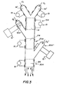
- the plasma generator may have different constructions, depending on whether it is a plasma generator by capacitive effect 15, of a high frequency plasma generator (HF) by induction 15 ', or a microwave plasma generator 15 "(see Fig. 3).
- Each of these generators can operate either in continuous mode or in pulse mode.
- One of the preferred generation methods of plasma is by pulses whose characteristics make it possible to generate plasmas producing interfering shock waves.
- the duration of the front of voltage growth, pulse duration, and frequency are selected in order to regularly generate shock waves in the plasma.
- These shock waves interfering on the one hand with the walls of the reactor, and, on the other hand between them and with the particles of the plasma, generate oscillations, especially ultrasonic, of the medium, strongly intensifying film deposition method.
- the process of generating a plasma atmospheric impulse makes it possible to create a uniform plasma in a given volume.
- the plasma reactor 4 may have a shape essentially parallelepiped, two opposite faces 19, 21 being covered by electrodes 23, 25.
- One of the electrodes 23 comprises metal needles 27 and is connected to a current source 29 at high frequency, by pulse.
- the other electrode 23 is flat and connected to the ground.
- FIG. 1 In FIG. 1 is shown a configuration plasma generator parallelepipedic (planar geometry).
- the electrodes are in the form of two coaxial cylinders between which, parallel to the axis, passes the gaseous mixture and, radially, are generated the filament discharges that create the plasma medium activating.
- the central electrode on which, in this case, the needles are implanted metal at the source of high frequency current, the other electrode being connected to the earth.
- the electric discharge from the needles 27 first has the shape of cylindrical channels of diameter d (d - 0.5 mm) of irregular shape, connecting the voltage electrode 25 to the electrode to the ground 23
- the duration t 1 of the current pulse front is chosen such that the heating of the channel is isochoric, i.e. that t 1 ⁇ d / a where a is the speed of sound in the medium.
- the pressure increases in the channel, reaches and exceeds the critical value of forming a shock wave that propagates radially.
- the channel expands rapidly, the plasma being fed by the increasing current flowing through it.
- the pulse has a duration t 2 chosen so as to ensure the passage of the current through the entire section of the conduit: t 2 ⁇ L / a, where L is the distance between the needles of the electrode under tension.
- the passage of the current is then interrupted for a lapse of time t 3 less than or equal to the relaxation time (deionization) of the gaseous medium in which the discharge takes place. This interruption does not allow the discharge to contract and locate itself.
- the relaxation time of the system depends on the properties of the gaseous medium in which the discharge takes place and its hydrodynamic parameters. It is chosen and optimized empirically. During the operation of the plasma generator, the excitation of the medium proves homogeneous throughout the volume of the plasma, the uniformity being due, in particular, to the interference of the shock waves coming from the different channels.
- the frequency of the generator was 13.56 MHz.
- the hydrodynamic filter 6 arranged between the mixer and the plasma reactor is intended to standardize and stabilize the flow of the gas mixture so as to give it a relatively constant velocity profile V across the column of the gas flow, as illustrated in FIG. . 1a.
- the longitudinal velocity V (1) of the gas mixture in the mixing part is non-constant, the epure being chaotic, whereas after the passage of the hydrodynamic filter 6, the longitudinal velocity V (2) of the gaseous mixture is practically uniform , except at the periphery P which is occupied by the neutral gas Q3 introduced by the side inlets 12.
- the neutral gas mainly forms the boundary layer on the inner surface of the reactor wall, having the effect of cooling and cooling. isolate the reactor wall from the hot plasma, and secondly to move the nuclei away from the boundary layer.
- the gas in the boundary layer is separated from the main stream and discharged at the outlet of the reactor as described below.
- the hydrodynamic filter preferably comprises small longitudinal channels 17 aligned with the direction D of the flow of the gaseous mixture through the reactor, the channels having lengths which may vary according to the distance separating them from the center of the enclosure .
- the variation in length of the channels can be empirically determined according to the geometry and width of the chambers 13,14 and the flow rate of the flow. Since the velocity at the center of the gaseous mixture column would normally be higher than at the periphery, the profile 22 of the hydrodynamic filter 6 preferably has a convex shape, as shown in FIG. 1 and FIG. 1a.
- the hydrodynamic filter may have a construction resembling a "honeycomb".
- the device comprises a channel evacuation device 28 arranged to harvest only the gases and Q4 particles at the periphery of the flow. This helps to remove the kernels and grains of powder that has flowed down the wall in the boundary layer, and which have undergone a different grain treatment in the central major part of flow due to non-uniform flow velocity in the boundary layer, and the presence of the neutral gas Q3.
- the collector portion 8 may be provided with a cooling circuit 30 in order to protect it from thermal destruction and cool the gas mixture and grains of powder coming out of the reactor and collected by a filter or other separator (not shown) known from conventional powders.
- FIG. 2 illustrates a second embodiment of a manufacturing device of composite grain powder according to the invention.
- the device comprises separate pretreatment plasma reactors 4 ', 4 "in which the carrier gas carrying the cores Q1, respectively the gas of Q2 treatment, are introduced. It is also possible to inject a neutral gas Q3 on along the walls of each pretreatment reactor to form the layer limit as previously described in relation to the form of execution of the figure 1.
- Each pretreatment reactor 4 ', 4 " is provided with a hydrodynamic filter 6 at its entrance to standardize the purity of the longitudinal velocities of the gases introduced in these reactors.
- the output of pre-treatment reactors communicates with a main reactor of common plasma where the carrier gas carrying the cores and the process gas are mixed.
- Elements or turbulisation blades 34 advantageously cooled, arranged at the exit of pre-treatment reactors, create a turbulisation of the respective flows for ensure a good mix of process gases and cores in one part mixing chamber at the inlet of the main plasma reactor 4, and by the continued in the treatment zone 14 of the main reactor.
- the length of the flow path between the pretreatment plasma reactors 4 ', 4 "and the main reactor 4 is such that the nuclei and gases activated in the preprocessing areas 14 'and 14 "do not deactivate (i.e. transport time is less than the relaxation time).
- the process gas flows Q2 and gas carrying the Q1 kernel powder are therefore introduced into reactors of pre-treatment plasma 4 ', 4 "separated. hydrodynamic 6 and neutral gas flow Q3 injected at the periphery, they are homogenized and then enter plasma areas 14 ', 14 "where they are activated. The two flows then come together. To ensure a good mix they are turbulized by devices 34 which disturb the flow. The activated mixture enters a second plasma zone 14 where a new activation operates, which catalyzes the process of film deposition on the nuclei.
- Figure 3 illustrates another embodiment of the present invention. In this case, it is a question of creating a superposition of films of different compositions and physico-chemical properties on the same nucleus. This process in a device that includes several stages of plasma 104, 204, 304.
- the first stage 104 of the device of FIG. characteristics of the device shown in Figure 2. Downstream of the first floor 104, one injects into the stream containing grains covered with a first layer a treatment gas Q2 'of a new chemical composition, which in the plasma treatment zone 214 of the second stage 204 makes it possible to deposit a new layer on the grains.
- the new treatment gas Q2 ' may undergo pretreatment (activation) by plasma through a reactor of pretreatment plasma 104 "of the device, disposed at the exit of the first floor.
- a third layer is deposited in the zone treatment unit 314 of the third stage 304 with the injection of a treatment gas Q2 "of a new composition upstream of the third reactor.
- the new treatment gas Q2 " may undergo a plasma pretreatment (activation) through a plasma reactor pretreatment 204 "of the device, disposed at the exit of the second floor.
- device may have additional stages so that the process can be repeated consecutively as many times as there is need for layers on the initial nucleus.
- the components of the plasma generating the film are chosen so that the forces of attraction between the particles of the film have a centripetal component contributing to solidify the structure of the peripheral film envelope. This component is all the more so because the dimension of the nuclei is small. She is especially important in the case of submicron powders and nanoscale.
- a filler gas eg argon
- they can be subjected to the action of acoustic vibrations, in particular ultrasonic.
- These vibrations can be generated by a generator outside, or by the plasma itself, in a plasma generation mode by pulses as described later
- the gas treatment containing the chemical components (eg mixture of hexamethyldisilasane and oxygen vapors).
- the electrons of the plasma heat up the process gas, and on the other hand excite the atoms and molecules, which break them down to form radicals.
- these activated particles are very apt to form, on a solid surface, by example the surface of the nuclei, a film whose physicochemical properties such that the optical properties are different from the properties of the nuclei.
- the film deposition process is a saturated process, ie the deposit rate decreases exponentially with the thickness it is useful in some cases of overloading the process gas with its chemical components.
- the thickness of the saturated layer deposited on the nuclei is controlled by the presence time of the nuclei in the zone of Plasma treatment with activated treatment gas
- the initial nuclei can be subjected to prior excitation, either for example by heating or radiating them, or by subjecting them to the action of a plasma.
- the electrons of the plasma will activate the superficial bonds of the atoms of the surface. These will remain excited during a relaxation time during which, for the formation of said film takes place, these nuclei must meet the particles (activated) process gas.
- the process according to the invention is advantageous for obtaining properties special physicochemical properties, eg optical effects on powders which are at the origin of the manufacture of colors and varnishes.
Landscapes
- Physics & Mathematics (AREA)
- Engineering & Computer Science (AREA)
- Plasma & Fusion (AREA)
- Chemical & Material Sciences (AREA)
- Analytical Chemistry (AREA)
- Spectroscopy & Molecular Physics (AREA)
- Acoustics & Sound (AREA)
- Organic Chemistry (AREA)
- Chemical Kinetics & Catalysis (AREA)
- Physical Or Chemical Processes And Apparatus (AREA)
- Glanulating (AREA)
- Compositions Of Oxide Ceramics (AREA)
- Processes Of Treating Macromolecular Substances (AREA)
Claims (25)
- Ein Herstellungsverfahren für ein Pulver, das aus Verbundmaterialkörnern gebildet wird, die einen Kern sowie eine oder mehrere oberflächliche Schichten umfassen, weist die Schritte auf: Vermischen der Kerne der Körner mit einem Gas für plasmachemische Behandlung, Durchlaufen eines Plasmahauptreaktors durch einen Strom des Gemischs aus Kernen und Behandlungsgasen und Erzeugung eines Plasmas im Wesentlichen bei gleichförmigem Atmosphärendruck in einer Behandlungszone des Hauptreaktors, um eine plasmachemische Reaktion zwischen dem Behandlungsgas und den Oberflächen der Kerne zu bewirken und oberflächliche Schichten auf diesen Kernen zu bilden, während der Strom des Gemischs den Reaktor durchläuft.
- Pulverherstellungsverfahren nach Anspruch 1, dadurch gekennzeichnet, dass die Oberfläche der Kerne im Voraus stromauf von der Plasmabehandlungszone des Hauptreaktors aktiviert wird.
- Pulverherstellungsverfahren nach Anspruch 1 oder 2, dadurch gekennzeichnet, dass die Anregungsenergie der Atome oder Moleküle des Behandlungsgases, die die auf dem Kern abgeschiedene Schicht erzeugen, zwischen 0,02 eV je Atom oder Molekül und der thermischen Zersetzungsenergie des Kems liegt.
- Verfahren nach einem der vorangehenden Ansprüche, dadurch gekennzeichnet, dass das Plasma durch Impulse erzeugt wird, deren Flanke, Dauer und Frequenz so gewählt sind, dass sie Stosswellen erzeugen, die akustische Vibrationen erzeugen.
- Verfahren nach einem der vorangehenden Ansprüche, dadurch gekennzeichnet, dass vermittels eines externen Schallgenerators im Plasma akustische Vibrationen erzeugt werden.
- Verfahren nach einem der vorangehenden Ansprüche, dadurch gekennzeichnet, dass die Behandlungsgase und das die Kerne enthaltende Trägergas stromauf von der Plasmabehandlungszone homogen vermischt werden.
- Verfahren nach dem vorangehenden Anspruch, dadurch gekennzeichnet, dass der Strom der Gasmischung vor seiner Anregung durch ein Plasma mittels eines hydrodynamischen Filters gleichförmig gemacht wird.
- Verfahren nach einem der vorangehenden Ansprüche, dadurch gekennzeichnet, dass ein neutrales Gas entlang der Wandungen des oder der Plasmareaktoren eingeblasen wird, um die Grenzschicht von Gasen auf der Innenseite dieser Wandungen zu bilden.
- Verfahren nach einem der vorangehenden Ansprüche, dadurch gekennzeichnet, dass die Ströme der Behandlungsgase und der Strom des die Kerne mitführenden Trägergases getrennt angeregt und nach ihrer Anregung in Berührung gebracht werden, wobei die Zeit zwischen der Anregung und der Kontaktierung kürzer als die Relaxationszeit der Anregung der Gaskomponenten und der Kerne ist.
- Verfahren nach einem der vorangehenden Ansprüche, dadurch gekennzeichnet, dass der Durchsatz des Behandlungsgases so gewählt wird, dass eine Sättigung des Abscheidungsprozesses der oberflächlichen Schicht auf den Kernen erreicht wird, wobei die Dicke der abgeschiedenen Schicht durch die Zeit der Anwesenheit der Kerne mit den Behandlungsgasen in der Plasmabehandlungszone gesteuert wird.
- Vorrichtung zur Ausführung eines Herstellungsverfahrens nach einem der Ansprüche 1 bis 10 für ein Pulver, das aus Verbundmaterialkörnern gebildet wird, die aus einem Kern und einer oder mehreren oberflächlichen Schichten bestehen, einen Plasmahauptreaktor (4, 10, 204, 304) aufweisend, der bei atmosphärischem Druck arbeitet, wobei der Reaktor eine Vorrichtung zur Plasmaerzeugung (15) und eine Kammer (14), die eine Plasmabehandlungszone definiert, die von einem Strom des Gemischs der Gase für die plasmachemische Behandlung und der Kerne durchflossen wird, sowie einen Mischabschnitt (2, 2') stromauf von der Behandlungszone umfasst, um die Behandlungsgase und die durch ein Trägergas mitgeführten Kerne zu vermischen, dadurch gekennzeichnet, dass sie zumindest ein hydrodynamisches Filter (6, 6', 6") stromauf von der Plasmabehandlungszone umfasst, um die Geschwindigkeit des Gemischs von Gasen und Kernen, die das hydrodynamische Filter durchlaufen, gleichförmig zu machen.
- Vorrichtung nach dem vorangehenden Anspruch, dadurch gekennzeichnet, dass das hydrodynamische Filter zwischen dem Mischabschnitt (2) und der Plasmabehandlungszone (14) angeordnet ist.
- Vorrichtung nach einem der Ansprüche 11 bis 12, dadurch gekennzeichnet, dass sie Plasmavorbehandlungsreaktoren (4', 4") stromauf vom Plasmahauptreaktor aufweist, die es gestatten, den Strom des Behandlungsgases und die durch ein Trägergas mitgeführten Kerne getrennt zu aktivieren.
- Vorrichtung nach dem vorangehenden Anspruch, dadurch gekennzeichnet, dass jeder Plasmavorbehandlungsreaktor stromauf von seiner Plasmabehandlungszone (14', 14") mit einem der hydrodynamischen Filter ausgerüstet ist.
- Vorrichtung nach einem der Ansprüche 11 bis 14, dadurch gekennzeichnet, dass sie eine oder mehrere externe Quellen akustischer Schwingungen umfasst.
- Vorrichtung nach einem der Ansprüche 11 bis 15, dadurch gekennzeichnet, dass die Plasmaerzeugungsvorrichtung Mittel zur Plasmaerzeugung durch Impulse umfasst.
- Vorrichtung nach einem der Ansprüche 11 bis 16, dadurch gekennzeichnet, dass sie seitliche Eingänge (12) zum Einblasen eines neutralen Gases entlang der Innenseite der Wandung des oder der Plasmareaktoren (4, 4', 4") umfasst.
- Vorrichtung nach einem der Ansprüche 11 bis 17, dadurch gekennzeichnet, dass sie einen Sammelabschnitt (8) am Ausgang der Vorrichtung umfasst, der einen peripheren Kanal für den Abzug der Gase und der Kerne umfasst, die in der Grenzschicht entlang der Innenseite des Reaktors fliessen.
- Vorrichtung nach einem der Ansprüche 11 bis 18, dadurch gekennzeichnet, dass das hydrodynamische Filter eine Mehrzahl kleiner Längskanäle umfasst, die in der Richtung der Strömung durch den Reaktor verlaufen, dem es vorgeschaltet ist.
- Vorrichtung nach einem der Ansprüche 11 bis 19, dadurch gekennzeichnet, dass die Plasmaerzeugungsvorrichtung Elektroden (23, 25) umfasst, die zu beiden Seiten der Plasmabehandlungszone (14) angeordnet sind, wobei die eine der Elektroden Metallnadeln (27) umfasst, die auf der Elektrodenoberfläche verteilt und zur anderen Elektrode hin gerichtet sind, während die HF-Stromquelle eine lmpulsquelle ist.
- Vorrichtung nach dem vorangehenden Anspruch, dadurch gekennzeichnet, dass der Plasmareaktor die Gestalt eines Parallelepipeds besitzt, wobei die Elektroden auf den einander gegenüberliegenden, zur Richtung der Gasströmung parallelen Seiten angeordnet sind.
- Vorrichtung nach Anspruch 20, dadurch gekennzeichnet, dass der Plasmareaktor zylindrisch und aus zwei koaxialen Elektroden zusammengesetzt ist, wobei ihre Achsen parallel zur Richtung der Gasströmung sind.
- Vorrichtung nach dem vorangehenden Anspruch, dadurch gekennzeichnet, dass die zentrale Elektrode mit der HF-Impulsstromquelle verbunden ist und die Metallnadeln umfasst, während die Aussenelektrode geerdet ist.
- Vorrichtung nach Anspruch 19, dadurch gekennzeichnet, dass die Länge der Längskanäle in der Mitte des Filters grösser als mit zunehmender Entfernung von der Mitte ist.
- Vorrichtung nach Anspruch 19 oder 24, dadurch gekennzeichnet, dass die Kanäle aus dünnen Wänden einer Struktur im Wesentlichen in Bienenwabengestalt gebildet werden.
Priority Applications (1)
| Application Number | Priority Date | Filing Date | Title |
|---|---|---|---|
| EP02762661A EP1420876B1 (de) | 2001-08-31 | 2002-09-02 | Verfahren und vorrichtung zur herstellung von pulver aus verbundmaterial |
Applications Claiming Priority (4)
| Application Number | Priority Date | Filing Date | Title |
|---|---|---|---|
| EP01120974 | 2001-08-31 | ||
| EP01120974 | 2001-08-31 | ||
| PCT/IB2002/003551 WO2003018185A2 (fr) | 2001-08-31 | 2002-09-02 | Procede de fabrication de poudre de grains composites et dispositif pour la mise en oeuvre du procede |
| EP02762661A EP1420876B1 (de) | 2001-08-31 | 2002-09-02 | Verfahren und vorrichtung zur herstellung von pulver aus verbundmaterial |
Publications (2)
| Publication Number | Publication Date |
|---|---|
| EP1420876A2 EP1420876A2 (de) | 2004-05-26 |
| EP1420876B1 true EP1420876B1 (de) | 2005-08-10 |
Family
ID=8178494
Family Applications (1)
| Application Number | Title | Priority Date | Filing Date |
|---|---|---|---|
| EP02762661A Expired - Lifetime EP1420876B1 (de) | 2001-08-31 | 2002-09-02 | Verfahren und vorrichtung zur herstellung von pulver aus verbundmaterial |
Country Status (7)
| Country | Link |
|---|---|
| US (1) | US7172790B2 (de) |
| EP (1) | EP1420876B1 (de) |
| JP (1) | JP2005503250A (de) |
| AT (1) | ATE301496T1 (de) |
| DE (1) | DE60205493T2 (de) |
| ES (1) | ES2247370T3 (de) |
| WO (1) | WO2003018185A2 (de) |
Families Citing this family (32)
| Publication number | Priority date | Publication date | Assignee | Title |
|---|---|---|---|---|
| US7288293B2 (en) * | 2001-03-27 | 2007-10-30 | Apit Corp. S.A. | Process for plasma surface treatment and device for realizing the process |
| JP5628472B2 (ja) * | 2004-04-19 | 2014-11-19 | エスディーシーマテリアルズ, インコーポレイテッド | 気相合成による高スループットの材料発見方法 |
| US8240190B2 (en) * | 2005-08-23 | 2012-08-14 | Uwm Research Foundation, Inc. | Ambient-temperature gas sensor |
| US8268405B2 (en) * | 2005-08-23 | 2012-09-18 | Uwm Research Foundation, Inc. | Controlled decoration of carbon nanotubes with aerosol nanoparticles |
| US8142619B2 (en) | 2007-05-11 | 2012-03-27 | Sdc Materials Inc. | Shape of cone and air input annulus |
| US8552650B2 (en) * | 2007-07-12 | 2013-10-08 | Imagineering, Inc. | Plasma formation region control apparatus and plasma processing apparatus |
| US8575059B1 (en) | 2007-10-15 | 2013-11-05 | SDCmaterials, Inc. | Method and system for forming plug and play metal compound catalysts |
| US8803025B2 (en) | 2009-12-15 | 2014-08-12 | SDCmaterials, Inc. | Non-plugging D.C. plasma gun |
| US8470112B1 (en) | 2009-12-15 | 2013-06-25 | SDCmaterials, Inc. | Workflow for novel composite materials |
| US9149797B2 (en) | 2009-12-15 | 2015-10-06 | SDCmaterials, Inc. | Catalyst production method and system |
| US20110144382A1 (en) * | 2009-12-15 | 2011-06-16 | SDCmaterials, Inc. | Advanced catalysts for fine chemical and pharmaceutical applications |
| US8557727B2 (en) | 2009-12-15 | 2013-10-15 | SDCmaterials, Inc. | Method of forming a catalyst with inhibited mobility of nano-active material |
| US9090475B1 (en) | 2009-12-15 | 2015-07-28 | SDCmaterials, Inc. | In situ oxide removal, dispersal and drying for silicon SiO2 |
| US8652992B2 (en) | 2009-12-15 | 2014-02-18 | SDCmaterials, Inc. | Pinning and affixing nano-active material |
| US8545652B1 (en) | 2009-12-15 | 2013-10-01 | SDCmaterials, Inc. | Impact resistant material |
| US9126191B2 (en) * | 2009-12-15 | 2015-09-08 | SDCmaterials, Inc. | Advanced catalysts for automotive applications |
| US8669202B2 (en) | 2011-02-23 | 2014-03-11 | SDCmaterials, Inc. | Wet chemical and plasma methods of forming stable PtPd catalysts |
| JP2013008770A (ja) * | 2011-06-23 | 2013-01-10 | Iwatani Internatl Corp | 成膜装置での堆積物クリーニング方法 |
| US8679433B2 (en) | 2011-08-19 | 2014-03-25 | SDCmaterials, Inc. | Coated substrates for use in catalysis and catalytic converters and methods of coating substrates with washcoat compositions |
| WO2013105659A1 (ja) * | 2012-01-13 | 2013-07-18 | 国立大学法人大阪大学 | 活性種照射装置、活性種照射方法及び活性種被照射物作製方法 |
| US9511352B2 (en) | 2012-11-21 | 2016-12-06 | SDCmaterials, Inc. | Three-way catalytic converter using nanoparticles |
| US9156025B2 (en) | 2012-11-21 | 2015-10-13 | SDCmaterials, Inc. | Three-way catalytic converter using nanoparticles |
| WO2015013545A1 (en) | 2013-07-25 | 2015-01-29 | SDCmaterials, Inc. | Washcoats and coated substrates for catalytic converters |
| WO2015061477A1 (en) | 2013-10-22 | 2015-04-30 | SDCmaterials, Inc. | Catalyst design for heavy-duty diesel combustion engines |
| KR20160074574A (ko) | 2013-10-22 | 2016-06-28 | 에스디씨머티리얼스, 인코포레이티드 | 희박 NOx 트랩의 조성물 |
| US9687811B2 (en) | 2014-03-21 | 2017-06-27 | SDCmaterials, Inc. | Compositions for passive NOx adsorption (PNA) systems and methods of making and using same |
| US9550694B2 (en) | 2014-03-31 | 2017-01-24 | Corning Incorporated | Methods and apparatus for material processing using plasma thermal source |
| US9533909B2 (en) | 2014-03-31 | 2017-01-03 | Corning Incorporated | Methods and apparatus for material processing using atmospheric thermal plasma reactor |
| WO2016075750A1 (ja) * | 2014-11-11 | 2016-05-19 | 富士機械製造株式会社 | 大気圧プラズマ処理装置、およびプラズマ処理方法 |
| US20160200618A1 (en) | 2015-01-08 | 2016-07-14 | Corning Incorporated | Method and apparatus for adding thermal energy to a glass melt |
| EP3363270B1 (de) * | 2015-10-12 | 2019-12-25 | Trumpf Laser- und Systemtechnik GmbH | Verfahren und vorrichtung zur erzeugung von plasma- bzw. laserpulsen mittels hochfrequenz-anregungspulsen, insbesondere ein gasentladungslaser, sowie steuereinheit für einen hochfrequenz-anregungspuls-generator |
| EP3758866A4 (de) | 2018-06-08 | 2021-09-08 | Hewlett-Packard Development Company, L.P. | Pulverbettmaterialien |
Family Cites Families (18)
| Publication number | Priority date | Publication date | Assignee | Title |
|---|---|---|---|---|
| US3247014A (en) * | 1963-05-29 | 1966-04-19 | Battelle Development Corp | Method of coating solid particles |
| US4612432A (en) | 1984-09-14 | 1986-09-16 | Monolithic Memories, Inc. | Etching plasma generator diffusor and cap |
| US4859493A (en) * | 1987-03-31 | 1989-08-22 | Lemelson Jerome H | Methods of forming synthetic diamond coatings on particles using microwaves |
| US5364562A (en) * | 1990-04-17 | 1994-11-15 | Xingwu Wang | Aerosol-plasma deposition of insulating oxide powder |
| JPH05246786A (ja) * | 1991-07-02 | 1993-09-24 | L'air Liquide | コア粉体の存在下で化学蒸着法により珪素ベース超微粒子をコア粉に均一に塗布する方法 |
| JP3283889B2 (ja) * | 1991-07-24 | 2002-05-20 | 株式会社きもと | 防錆処理方法 |
| US5569502A (en) * | 1992-09-11 | 1996-10-29 | Semiconductor Energy Laboratory Co., Ltd. | Film formation apparatus and method for forming a film |
| JP3545783B2 (ja) * | 1993-08-12 | 2004-07-21 | 株式会社日清製粉グループ本社 | 被覆粒子の製造方法 |
| US5408066A (en) * | 1993-10-13 | 1995-04-18 | Trapani; Richard D. | Powder injection apparatus for a plasma spray gun |
| US5609921A (en) * | 1994-08-26 | 1997-03-11 | Universite De Sherbrooke | Suspension plasma spray |
| US5876683A (en) * | 1995-11-02 | 1999-03-02 | Glumac; Nicholas | Combustion flame synthesis of nanophase materials |
| EP0861338A1 (de) * | 1995-11-13 | 1998-09-02 | IST Instant Surface Technology S.A. | Verfahren zur oberflächenbehandlung sowie vorrichtung zur dessen durchführung |
| DE69703649T2 (de) | 1996-02-06 | 2001-08-02 | E.I. Du Pont De Nemours And Co., Wilmington | Behandlung von deagglomerierten teilchen mit plasmaaktivierter spezies |
| US6015597A (en) * | 1997-11-26 | 2000-01-18 | 3M Innovative Properties Company | Method for coating diamond-like networks onto particles |
| KR100279963B1 (ko) * | 1997-12-30 | 2001-04-02 | 윤종용 | 반도체소자제조용가스디퓨져및이를설치한반응로 |
| JP4004675B2 (ja) * | 1999-01-29 | 2007-11-07 | 株式会社日清製粉グループ本社 | 酸化物被覆金属微粒子の製造方法 |
| US6415736B1 (en) * | 1999-06-30 | 2002-07-09 | Lam Research Corporation | Gas distribution apparatus for semiconductor processing |
| US6472632B1 (en) * | 1999-09-15 | 2002-10-29 | Nanoscale Engineering And Technology Corporation | Method and apparatus for direct electrothermal-physical conversion of ceramic into nanopowder |
-
2002
- 2002-09-02 ES ES02762661T patent/ES2247370T3/es not_active Expired - Lifetime
- 2002-09-02 WO PCT/IB2002/003551 patent/WO2003018185A2/fr active IP Right Grant
- 2002-09-02 US US10/486,888 patent/US7172790B2/en not_active Expired - Fee Related
- 2002-09-02 JP JP2003522692A patent/JP2005503250A/ja active Pending
- 2002-09-02 EP EP02762661A patent/EP1420876B1/de not_active Expired - Lifetime
- 2002-09-02 DE DE60205493T patent/DE60205493T2/de not_active Expired - Fee Related
- 2002-09-02 AT AT02762661T patent/ATE301496T1/de not_active IP Right Cessation
Also Published As
| Publication number | Publication date |
|---|---|
| US20040238345A1 (en) | 2004-12-02 |
| EP1420876A2 (de) | 2004-05-26 |
| US7172790B2 (en) | 2007-02-06 |
| WO2003018185A3 (fr) | 2003-09-18 |
| ATE301496T1 (de) | 2005-08-15 |
| DE60205493D1 (de) | 2005-09-15 |
| JP2005503250A (ja) | 2005-02-03 |
| DE60205493T2 (de) | 2006-06-01 |
| ES2247370T3 (es) | 2006-03-01 |
| WO2003018185A2 (fr) | 2003-03-06 |
Similar Documents
| Publication | Publication Date | Title |
|---|---|---|
| EP1420876B1 (de) | Verfahren und vorrichtung zur herstellung von pulver aus verbundmaterial | |
| FR2636079A1 (fr) | Procede de revetement de substrats par depot en phase vapeur | |
| JP5589839B2 (ja) | プラズマ処理装置およびこれを用いたアモルファスシリコン薄膜の製造方法 | |
| CA2423138A1 (fr) | Procede et dispositif pour traiter des substrats metalliques au defile par plasma | |
| TW201015653A (en) | Plasma processing apparatus and plasma processing method | |
| EP2302093A1 (de) | Herstellungsverfahren für bedampfungsvorrichtung und dünnfilmvorrichtung | |
| EP0685143B1 (de) | Lineare mikrowellenquelle zur plasmabehandlung von flächen. | |
| FR2993576A1 (fr) | Dispositif de traitement d'un objet par plasma | |
| EP3945361A1 (de) | Akusto-optischer modulator | |
| EP1374276B1 (de) | Verfahren und vorrichtung zur plasmabehandlung von oberflächen | |
| Adhikary et al. | Observation of rarefactive ion acoustic solitary waves in dusty plasma containing negative ions | |
| EP2053631A1 (de) | Verfahren und Vorrichtung zur Plasma-Behandlung Substrate im Durchlauf | |
| WO2008009558A1 (fr) | Dispositif et procédé de production et de confinement d'un plasma | |
| EP2305855A1 (de) | Herstellungsverfahren für bedampfungsvorrichtung und dünnfilmvorrichtung | |
| EP0578580B1 (de) | Anordnung zur Polymer-Beschichtung mittels einen durch Mikrowellen angeregten Plasma | |
| WO1999046964A1 (fr) | Procede de traitement de surface d'un materiau ou d'un objet et dispositif pour la mise en oeuvre du procede | |
| WO2013092228A1 (fr) | Procédé de synthèse physique de nanopoudres de carbure de silicium permettant de maintenir les caractéristiques physico-chimiques du carbure de silicium au cours de la synthèse. | |
| EP1526875B1 (de) | Leistungsstarkes verfahren zur plasmasterilisierung | |
| RU2788258C1 (ru) | Газоструйный способ осаждения алмазных пленок с активацией в плазме свч разряда | |
| WO1999046428A1 (fr) | Procede et installation de traitement de surface d'une piece metallique | |
| JP3769059B2 (ja) | 超音波・プラズマ・粒子ビーム複合プロセス装置及び薄膜の形成方法並びに表面の平滑化方法 | |
| EP2654071B1 (de) | Kapazitiv gekoppelter Plasmareaktor für Dünnfilmablagerung | |
| EP1094691B1 (de) | Verfahren zur Plasmaerzeugung durch kapazitive gleichmässige Entladungen und Implementierungsvorrichtung dafür | |
| Kamal-Al-Hassan et al. | Excitation of ion-wave wakefield by the resonant absorption of a short pulsed microwave with plasma | |
| FR2555360A1 (fr) | Dispositif pour la realisation de couches dielectriques minces a la surface de corps solides |
Legal Events
| Date | Code | Title | Description |
|---|---|---|---|
| PUAI | Public reference made under article 153(3) epc to a published international application that has entered the european phase |
Free format text: ORIGINAL CODE: 0009012 |
|
| AK | Designated contracting states |
Kind code of ref document: A2 Designated state(s): AT BE BG CH CY CZ DE DK EE ES FI FR GB GR IE IT LI LU MC NL PT SE SK TR |
|
| AX | Request for extension of the european patent |
Extension state: AL LT LV MK RO SI |
|
| 17P | Request for examination filed |
Effective date: 20040117 |
|
| 17Q | First examination report despatched |
Effective date: 20040902 |
|
| GRAP | Despatch of communication of intention to grant a patent |
Free format text: ORIGINAL CODE: EPIDOSNIGR1 |
|
| GRAS | Grant fee paid |
Free format text: ORIGINAL CODE: EPIDOSNIGR3 |
|
| GRAA | (expected) grant |
Free format text: ORIGINAL CODE: 0009210 |
|
| AK | Designated contracting states |
Kind code of ref document: B1 Designated state(s): AT BE BG CH CY CZ DE DK EE ES FI FR GB GR IE IT LI LU MC NL PT SE SK TR |
|
| PG25 | Lapsed in a contracting state [announced via postgrant information from national office to epo] |
Ref country code: EE Free format text: LAPSE BECAUSE OF FAILURE TO SUBMIT A TRANSLATION OF THE DESCRIPTION OR TO PAY THE FEE WITHIN THE PRESCRIBED TIME-LIMIT Effective date: 20050810 Ref country code: SK Free format text: LAPSE BECAUSE OF FAILURE TO SUBMIT A TRANSLATION OF THE DESCRIPTION OR TO PAY THE FEE WITHIN THE PRESCRIBED TIME-LIMIT Effective date: 20050810 Ref country code: TR Free format text: LAPSE BECAUSE OF FAILURE TO SUBMIT A TRANSLATION OF THE DESCRIPTION OR TO PAY THE FEE WITHIN THE PRESCRIBED TIME-LIMIT Effective date: 20050810 Ref country code: CZ Free format text: LAPSE BECAUSE OF FAILURE TO SUBMIT A TRANSLATION OF THE DESCRIPTION OR TO PAY THE FEE WITHIN THE PRESCRIBED TIME-LIMIT Effective date: 20050810 Ref country code: FI Free format text: LAPSE BECAUSE OF FAILURE TO SUBMIT A TRANSLATION OF THE DESCRIPTION OR TO PAY THE FEE WITHIN THE PRESCRIBED TIME-LIMIT Effective date: 20050810 Ref country code: AT Free format text: LAPSE BECAUSE OF FAILURE TO SUBMIT A TRANSLATION OF THE DESCRIPTION OR TO PAY THE FEE WITHIN THE PRESCRIBED TIME-LIMIT Effective date: 20050810 Ref country code: NL Free format text: LAPSE BECAUSE OF FAILURE TO SUBMIT A TRANSLATION OF THE DESCRIPTION OR TO PAY THE FEE WITHIN THE PRESCRIBED TIME-LIMIT Effective date: 20050810 Ref country code: IE Free format text: LAPSE BECAUSE OF FAILURE TO SUBMIT A TRANSLATION OF THE DESCRIPTION OR TO PAY THE FEE WITHIN THE PRESCRIBED TIME-LIMIT Effective date: 20050810 |
|
| REG | Reference to a national code |
Ref country code: GB Ref legal event code: FG4D Free format text: NOT ENGLISH |
|
| REG | Reference to a national code |
Ref country code: CH Ref legal event code: EP |
|
| PG25 | Lapsed in a contracting state [announced via postgrant information from national office to epo] |
Ref country code: CY Free format text: LAPSE BECAUSE OF FAILURE TO SUBMIT A TRANSLATION OF THE DESCRIPTION OR TO PAY THE FEE WITHIN THE PRESCRIBED TIME-LIMIT Effective date: 20050902 |
|
| REG | Reference to a national code |
Ref country code: IE Ref legal event code: FG4D Free format text: LANGUAGE OF EP DOCUMENT: FRENCH |
|
| REF | Corresponds to: |
Ref document number: 60205493 Country of ref document: DE Date of ref document: 20050915 Kind code of ref document: P |
|
| PG25 | Lapsed in a contracting state [announced via postgrant information from national office to epo] |
Ref country code: MC Free format text: LAPSE BECAUSE OF NON-PAYMENT OF DUE FEES Effective date: 20050930 |
|
| REG | Reference to a national code |
Ref country code: CH Ref legal event code: NV Representative=s name: WILLIAM BLANC & CIE CONSEILS EN PROPRIETE INDUSTRI |
|
| PG25 | Lapsed in a contracting state [announced via postgrant information from national office to epo] |
Ref country code: DK Free format text: LAPSE BECAUSE OF FAILURE TO SUBMIT A TRANSLATION OF THE DESCRIPTION OR TO PAY THE FEE WITHIN THE PRESCRIBED TIME-LIMIT Effective date: 20051110 Ref country code: GR Free format text: LAPSE BECAUSE OF FAILURE TO SUBMIT A TRANSLATION OF THE DESCRIPTION OR TO PAY THE FEE WITHIN THE PRESCRIBED TIME-LIMIT Effective date: 20051110 Ref country code: BG Free format text: LAPSE BECAUSE OF FAILURE TO SUBMIT A TRANSLATION OF THE DESCRIPTION OR TO PAY THE FEE WITHIN THE PRESCRIBED TIME-LIMIT Effective date: 20051110 Ref country code: SE Free format text: LAPSE BECAUSE OF FAILURE TO SUBMIT A TRANSLATION OF THE DESCRIPTION OR TO PAY THE FEE WITHIN THE PRESCRIBED TIME-LIMIT Effective date: 20051110 |
|
| GBT | Gb: translation of ep patent filed (gb section 77(6)(a)/1977) |
Effective date: 20051028 |
|
| PG25 | Lapsed in a contracting state [announced via postgrant information from national office to epo] |
Ref country code: PT Free format text: LAPSE BECAUSE OF FAILURE TO SUBMIT A TRANSLATION OF THE DESCRIPTION OR TO PAY THE FEE WITHIN THE PRESCRIBED TIME-LIMIT Effective date: 20060110 |
|
| NLV1 | Nl: lapsed or annulled due to failure to fulfill the requirements of art. 29p and 29m of the patents act | ||
| REG | Reference to a national code |
Ref country code: ES Ref legal event code: FG2A Ref document number: 2247370 Country of ref document: ES Kind code of ref document: T3 |
|
| REG | Reference to a national code |
Ref country code: IE Ref legal event code: FD4D |
|
| PLBE | No opposition filed within time limit |
Free format text: ORIGINAL CODE: 0009261 |
|
| STAA | Information on the status of an ep patent application or granted ep patent |
Free format text: STATUS: NO OPPOSITION FILED WITHIN TIME LIMIT |
|
| 26N | No opposition filed |
Effective date: 20060511 |
|
| PGFP | Annual fee paid to national office [announced via postgrant information from national office to epo] |
Ref country code: DE Payment date: 20070921 Year of fee payment: 6 |
|
| PGFP | Annual fee paid to national office [announced via postgrant information from national office to epo] |
Ref country code: LU Payment date: 20070926 Year of fee payment: 6 |
|
| PGFP | Annual fee paid to national office [announced via postgrant information from national office to epo] |
Ref country code: ES Payment date: 20070927 Year of fee payment: 6 |
|
| PGFP | Annual fee paid to national office [announced via postgrant information from national office to epo] |
Ref country code: GB Payment date: 20070914 Year of fee payment: 6 |
|
| PGFP | Annual fee paid to national office [announced via postgrant information from national office to epo] |
Ref country code: IT Payment date: 20070922 Year of fee payment: 6 |
|
| PGFP | Annual fee paid to national office [announced via postgrant information from national office to epo] |
Ref country code: CH Payment date: 20071030 Year of fee payment: 6 |
|
| PGFP | Annual fee paid to national office [announced via postgrant information from national office to epo] |
Ref country code: BE Payment date: 20071004 Year of fee payment: 6 |
|
| PGFP | Annual fee paid to national office [announced via postgrant information from national office to epo] |
Ref country code: FR Payment date: 20070914 Year of fee payment: 6 |
|
| BERE | Be: lapsed |
Owner name: APIT CORP. SA Effective date: 20080930 |
|
| REG | Reference to a national code |
Ref country code: CH Ref legal event code: PL |
|
| GBPC | Gb: european patent ceased through non-payment of renewal fee |
Effective date: 20080902 |
|
| REG | Reference to a national code |
Ref country code: FR Ref legal event code: ST Effective date: 20090529 |
|
| PG25 | Lapsed in a contracting state [announced via postgrant information from national office to epo] |
Ref country code: BE Free format text: LAPSE BECAUSE OF NON-PAYMENT OF DUE FEES Effective date: 20080930 |
|
| PG25 | Lapsed in a contracting state [announced via postgrant information from national office to epo] |
Ref country code: IT Free format text: LAPSE BECAUSE OF NON-PAYMENT OF DUE FEES Effective date: 20080902 Ref country code: DE Free format text: LAPSE BECAUSE OF NON-PAYMENT OF DUE FEES Effective date: 20090401 |
|
| PG25 | Lapsed in a contracting state [announced via postgrant information from national office to epo] |
Ref country code: CH Free format text: LAPSE BECAUSE OF NON-PAYMENT OF DUE FEES Effective date: 20080930 Ref country code: FR Free format text: LAPSE BECAUSE OF NON-PAYMENT OF DUE FEES Effective date: 20080930 Ref country code: LI Free format text: LAPSE BECAUSE OF NON-PAYMENT OF DUE FEES Effective date: 20080930 |
|
| REG | Reference to a national code |
Ref country code: ES Ref legal event code: FD2A Effective date: 20080903 |
|
| PG25 | Lapsed in a contracting state [announced via postgrant information from national office to epo] |
Ref country code: GB Free format text: LAPSE BECAUSE OF NON-PAYMENT OF DUE FEES Effective date: 20080902 |
|
| PG25 | Lapsed in a contracting state [announced via postgrant information from national office to epo] |
Ref country code: ES Free format text: LAPSE BECAUSE OF NON-PAYMENT OF DUE FEES Effective date: 20080903 |
|
| PG25 | Lapsed in a contracting state [announced via postgrant information from national office to epo] |
Ref country code: LU Free format text: LAPSE BECAUSE OF NON-PAYMENT OF DUE FEES Effective date: 20080902 |