EP1420080A2 - Apparatus and method for hybrid chemical deposition processes - Google Patents
Apparatus and method for hybrid chemical deposition processes Download PDFInfo
- Publication number
- EP1420080A2 EP1420080A2 EP03257169A EP03257169A EP1420080A2 EP 1420080 A2 EP1420080 A2 EP 1420080A2 EP 03257169 A EP03257169 A EP 03257169A EP 03257169 A EP03257169 A EP 03257169A EP 1420080 A2 EP1420080 A2 EP 1420080A2
- Authority
- EP
- European Patent Office
- Prior art keywords
- gas
- chamber body
- gas conduit
- mixing channel
- compounds
- Prior art date
- Legal status (The legal status is an assumption and is not a legal conclusion. Google has not performed a legal analysis and makes no representation as to the accuracy of the status listed.)
- Withdrawn
Links
Images


Classifications
-
- C—CHEMISTRY; METALLURGY
- C23—COATING METALLIC MATERIAL; COATING MATERIAL WITH METALLIC MATERIAL; CHEMICAL SURFACE TREATMENT; DIFFUSION TREATMENT OF METALLIC MATERIAL; COATING BY VACUUM EVAPORATION, BY SPUTTERING, BY ION IMPLANTATION OR BY CHEMICAL VAPOUR DEPOSITION, IN GENERAL; INHIBITING CORROSION OF METALLIC MATERIAL OR INCRUSTATION IN GENERAL
- C23C—COATING METALLIC MATERIAL; COATING MATERIAL WITH METALLIC MATERIAL; SURFACE TREATMENT OF METALLIC MATERIAL BY DIFFUSION INTO THE SURFACE, BY CHEMICAL CONVERSION OR SUBSTITUTION; COATING BY VACUUM EVAPORATION, BY SPUTTERING, BY ION IMPLANTATION OR BY CHEMICAL VAPOUR DEPOSITION, IN GENERAL
- C23C16/00—Chemical coating by decomposition of gaseous compounds, without leaving reaction products of surface material in the coating, i.e. chemical vapour deposition [CVD] processes
- C23C16/44—Chemical coating by decomposition of gaseous compounds, without leaving reaction products of surface material in the coating, i.e. chemical vapour deposition [CVD] processes characterised by the method of coating
- C23C16/455—Chemical coating by decomposition of gaseous compounds, without leaving reaction products of surface material in the coating, i.e. chemical vapour deposition [CVD] processes characterised by the method of coating characterised by the method used for introducing gases into reaction chamber or for modifying gas flows in reaction chamber
- C23C16/45523—Pulsed gas flow or change of composition over time
- C23C16/45525—Atomic layer deposition [ALD]
- C23C16/45544—Atomic layer deposition [ALD] characterized by the apparatus
-
- C—CHEMISTRY; METALLURGY
- C23—COATING METALLIC MATERIAL; COATING MATERIAL WITH METALLIC MATERIAL; CHEMICAL SURFACE TREATMENT; DIFFUSION TREATMENT OF METALLIC MATERIAL; COATING BY VACUUM EVAPORATION, BY SPUTTERING, BY ION IMPLANTATION OR BY CHEMICAL VAPOUR DEPOSITION, IN GENERAL; INHIBITING CORROSION OF METALLIC MATERIAL OR INCRUSTATION IN GENERAL
- C23C—COATING METALLIC MATERIAL; COATING MATERIAL WITH METALLIC MATERIAL; SURFACE TREATMENT OF METALLIC MATERIAL BY DIFFUSION INTO THE SURFACE, BY CHEMICAL CONVERSION OR SUBSTITUTION; COATING BY VACUUM EVAPORATION, BY SPUTTERING, BY ION IMPLANTATION OR BY CHEMICAL VAPOUR DEPOSITION, IN GENERAL
- C23C16/00—Chemical coating by decomposition of gaseous compounds, without leaving reaction products of surface material in the coating, i.e. chemical vapour deposition [CVD] processes
- C23C16/44—Chemical coating by decomposition of gaseous compounds, without leaving reaction products of surface material in the coating, i.e. chemical vapour deposition [CVD] processes characterised by the method of coating
- C23C16/455—Chemical coating by decomposition of gaseous compounds, without leaving reaction products of surface material in the coating, i.e. chemical vapour deposition [CVD] processes characterised by the method of coating characterised by the method used for introducing gases into reaction chamber or for modifying gas flows in reaction chamber
- C23C16/45502—Flow conditions in reaction chamber
- C23C16/45504—Laminar flow
-
- C—CHEMISTRY; METALLURGY
- C23—COATING METALLIC MATERIAL; COATING MATERIAL WITH METALLIC MATERIAL; CHEMICAL SURFACE TREATMENT; DIFFUSION TREATMENT OF METALLIC MATERIAL; COATING BY VACUUM EVAPORATION, BY SPUTTERING, BY ION IMPLANTATION OR BY CHEMICAL VAPOUR DEPOSITION, IN GENERAL; INHIBITING CORROSION OF METALLIC MATERIAL OR INCRUSTATION IN GENERAL
- C23C—COATING METALLIC MATERIAL; COATING MATERIAL WITH METALLIC MATERIAL; SURFACE TREATMENT OF METALLIC MATERIAL BY DIFFUSION INTO THE SURFACE, BY CHEMICAL CONVERSION OR SUBSTITUTION; COATING BY VACUUM EVAPORATION, BY SPUTTERING, BY ION IMPLANTATION OR BY CHEMICAL VAPOUR DEPOSITION, IN GENERAL
- C23C16/00—Chemical coating by decomposition of gaseous compounds, without leaving reaction products of surface material in the coating, i.e. chemical vapour deposition [CVD] processes
- C23C16/44—Chemical coating by decomposition of gaseous compounds, without leaving reaction products of surface material in the coating, i.e. chemical vapour deposition [CVD] processes characterised by the method of coating
- C23C16/455—Chemical coating by decomposition of gaseous compounds, without leaving reaction products of surface material in the coating, i.e. chemical vapour deposition [CVD] processes characterised by the method of coating characterised by the method used for introducing gases into reaction chamber or for modifying gas flows in reaction chamber
- C23C16/45502—Flow conditions in reaction chamber
- C23C16/45508—Radial flow
-
- C—CHEMISTRY; METALLURGY
- C23—COATING METALLIC MATERIAL; COATING MATERIAL WITH METALLIC MATERIAL; CHEMICAL SURFACE TREATMENT; DIFFUSION TREATMENT OF METALLIC MATERIAL; COATING BY VACUUM EVAPORATION, BY SPUTTERING, BY ION IMPLANTATION OR BY CHEMICAL VAPOUR DEPOSITION, IN GENERAL; INHIBITING CORROSION OF METALLIC MATERIAL OR INCRUSTATION IN GENERAL
- C23C—COATING METALLIC MATERIAL; COATING MATERIAL WITH METALLIC MATERIAL; SURFACE TREATMENT OF METALLIC MATERIAL BY DIFFUSION INTO THE SURFACE, BY CHEMICAL CONVERSION OR SUBSTITUTION; COATING BY VACUUM EVAPORATION, BY SPUTTERING, BY ION IMPLANTATION OR BY CHEMICAL VAPOUR DEPOSITION, IN GENERAL
- C23C16/00—Chemical coating by decomposition of gaseous compounds, without leaving reaction products of surface material in the coating, i.e. chemical vapour deposition [CVD] processes
- C23C16/44—Chemical coating by decomposition of gaseous compounds, without leaving reaction products of surface material in the coating, i.e. chemical vapour deposition [CVD] processes characterised by the method of coating
- C23C16/455—Chemical coating by decomposition of gaseous compounds, without leaving reaction products of surface material in the coating, i.e. chemical vapour deposition [CVD] processes characterised by the method of coating characterised by the method used for introducing gases into reaction chamber or for modifying gas flows in reaction chamber
- C23C16/45512—Premixing before introduction in the reaction chamber
-
- C—CHEMISTRY; METALLURGY
- C23—COATING METALLIC MATERIAL; COATING MATERIAL WITH METALLIC MATERIAL; CHEMICAL SURFACE TREATMENT; DIFFUSION TREATMENT OF METALLIC MATERIAL; COATING BY VACUUM EVAPORATION, BY SPUTTERING, BY ION IMPLANTATION OR BY CHEMICAL VAPOUR DEPOSITION, IN GENERAL; INHIBITING CORROSION OF METALLIC MATERIAL OR INCRUSTATION IN GENERAL
- C23C—COATING METALLIC MATERIAL; COATING MATERIAL WITH METALLIC MATERIAL; SURFACE TREATMENT OF METALLIC MATERIAL BY DIFFUSION INTO THE SURFACE, BY CHEMICAL CONVERSION OR SUBSTITUTION; COATING BY VACUUM EVAPORATION, BY SPUTTERING, BY ION IMPLANTATION OR BY CHEMICAL VAPOUR DEPOSITION, IN GENERAL
- C23C16/00—Chemical coating by decomposition of gaseous compounds, without leaving reaction products of surface material in the coating, i.e. chemical vapour deposition [CVD] processes
- C23C16/44—Chemical coating by decomposition of gaseous compounds, without leaving reaction products of surface material in the coating, i.e. chemical vapour deposition [CVD] processes characterised by the method of coating
- C23C16/455—Chemical coating by decomposition of gaseous compounds, without leaving reaction products of surface material in the coating, i.e. chemical vapour deposition [CVD] processes characterised by the method of coating characterised by the method used for introducing gases into reaction chamber or for modifying gas flows in reaction chamber
- C23C16/45561—Gas plumbing upstream of the reaction chamber
-
- C—CHEMISTRY; METALLURGY
- C23—COATING METALLIC MATERIAL; COATING MATERIAL WITH METALLIC MATERIAL; CHEMICAL SURFACE TREATMENT; DIFFUSION TREATMENT OF METALLIC MATERIAL; COATING BY VACUUM EVAPORATION, BY SPUTTERING, BY ION IMPLANTATION OR BY CHEMICAL VAPOUR DEPOSITION, IN GENERAL; INHIBITING CORROSION OF METALLIC MATERIAL OR INCRUSTATION IN GENERAL
- C23C—COATING METALLIC MATERIAL; COATING MATERIAL WITH METALLIC MATERIAL; SURFACE TREATMENT OF METALLIC MATERIAL BY DIFFUSION INTO THE SURFACE, BY CHEMICAL CONVERSION OR SUBSTITUTION; COATING BY VACUUM EVAPORATION, BY SPUTTERING, BY ION IMPLANTATION OR BY CHEMICAL VAPOUR DEPOSITION, IN GENERAL
- C23C16/00—Chemical coating by decomposition of gaseous compounds, without leaving reaction products of surface material in the coating, i.e. chemical vapour deposition [CVD] processes
- C23C16/44—Chemical coating by decomposition of gaseous compounds, without leaving reaction products of surface material in the coating, i.e. chemical vapour deposition [CVD] processes characterised by the method of coating
- C23C16/455—Chemical coating by decomposition of gaseous compounds, without leaving reaction products of surface material in the coating, i.e. chemical vapour deposition [CVD] processes characterised by the method of coating characterised by the method used for introducing gases into reaction chamber or for modifying gas flows in reaction chamber
- C23C16/45582—Expansion of gas before it reaches the substrate
-
- C—CHEMISTRY; METALLURGY
- C23—COATING METALLIC MATERIAL; COATING MATERIAL WITH METALLIC MATERIAL; CHEMICAL SURFACE TREATMENT; DIFFUSION TREATMENT OF METALLIC MATERIAL; COATING BY VACUUM EVAPORATION, BY SPUTTERING, BY ION IMPLANTATION OR BY CHEMICAL VAPOUR DEPOSITION, IN GENERAL; INHIBITING CORROSION OF METALLIC MATERIAL OR INCRUSTATION IN GENERAL
- C23C—COATING METALLIC MATERIAL; COATING MATERIAL WITH METALLIC MATERIAL; SURFACE TREATMENT OF METALLIC MATERIAL BY DIFFUSION INTO THE SURFACE, BY CHEMICAL CONVERSION OR SUBSTITUTION; COATING BY VACUUM EVAPORATION, BY SPUTTERING, BY ION IMPLANTATION OR BY CHEMICAL VAPOUR DEPOSITION, IN GENERAL
- C23C16/00—Chemical coating by decomposition of gaseous compounds, without leaving reaction products of surface material in the coating, i.e. chemical vapour deposition [CVD] processes
- C23C16/44—Chemical coating by decomposition of gaseous compounds, without leaving reaction products of surface material in the coating, i.e. chemical vapour deposition [CVD] processes characterised by the method of coating
- C23C16/54—Apparatus specially adapted for continuous coating
Definitions
- Embodiments of the invention generally relate to an apparatus and method for performing multiple vapor deposition processes in-situ. More particularly, embodiments of the invention relate to an improved gas delivery apparatus and method for depositing films in-situ using both cyclical layer and chemical vapor deposition techniques.
- Sub-quarter micron multilevel metallization is one of the key technologies for the next generation of very large scale integration (VLSI).
- VLSI very large scale integration
- the multilevel interconnects that lie at the heart of this technology possess high aspect ratio features, including contacts, vias, lines, or other apertures. Reliable formation of these features is very important to the success of VLSI and to the continued effort to increase quality and circuit density on individual substrates. Therefore, there is a great amount of ongoing effort being directed to the formation of void-free features having high aspect ratios of 4:1 (height:width) or greater.
- Copper has recently become a choice metal for filling VLSI features, such as sub-micron high aspect ratio, interconnect features, because copper and its alloys have lower resistivities than aluminum.
- copper and its alloys have a propensity to diffuse into surrounding materials such as silicon oxide, silicon, and other dielectric materials for example, causing an increase in the contact resistance of the circuit.
- Copper and its alloys also have a propensity to diffuse into surrounding elements such as transistor gates, capacitor dielectrics, transistor wells, transistor channels, electrical barrier regions, interconnects, among other known elements of integrated circuits. Barrier layers are, therefore, deposited prior to copper metallization to prevent or impede the diffusion of copper atoms.
- a typical sequence for forming an interconnect includes depositing one or more non-conductive layers, etching at least one of the layer(s) to form one or more features therein, depositing a barrier layer in the feature(s) and depositing one or more conductive layers, such as copper, to fill the feature.
- the barrier layer typically includes a refractory metal such as tungsten, titanium, tantalum, and nitrides thereof.
- tantalum nitride is one of the most desirable elements for use as a barrier layer because it has one of the lowest resistivities of the refractory metal nitrides and makes a good adhesion layer for copper metallization.
- a refractory metal nitride layer, such as tantalum nitride is typically deposited using conventional deposition techniques, such as physical vapor deposition (PVD) and chemical vapor deposition (CVD).
- Atomic layer deposition is one deposition technique being explored to deposit materials, such as a barrier layer, over features having high aspect ratios.
- ALD involves the sequential introduction of separate pulses of a first reactant and a second reactant, resulting in a self-limiting absorption of monolayers of material on the substrate surface. The reactants are sequentially introduced until a desired thickness of the deposited material is deposited.
- a pulse of a purge gas and/or a pump evacuation between the pulses of the reactants serves to reduce the likelihood of gas phase reactions of the reactants due to excess amounts of the reactants remaining in the chamber.
- a processed wafer is transferred between various processing chambers, consuming valuable processing time.
- the process wafer is subjected to a vacuum break between processing chambers and thus, the substrate is exposed to ambient conditions which, among other things, leads to oxidation of the substrate surface.
- metal oxides increase the resistance of the interconnect and reduce the electromigration resistance of vias and small features. Metal oxides also become a source of particle problems and reduce the reliability of the overall circuit. Metal oxides may also interfere with subsequent deposition processes by creating voids that promote uneven distribution of a subsequent depositing layer.
- the gas distribution assembly comprises a gas conduit in fluid communication with the chamber body, at least two separate flow paths in fluid communication with the gas conduit at a first end thereof, and at least one annular mixing channel disposed about the gas conduit at a second end thereof.
- Each isolated flow path comprises one or more high speed actuating valves, and the mixing channel is in fluid communication with the gas conduit via a plurality of nozzles formed therethrough.
- the flow paths are isolated from the mixing channel by a pressure differential created within the gas distribution assembly.
- a method for depositing multiple layers on a substrate surface by performing multiple deposition processes within a single processing chamber comprises positioning a substrate surface to be processed within a chamber body, delivering two or more compounds into the chamber body utilizing a gas distribution assembly disposed on the chamber body to deposit a film comprising a first material, and then delivering two or more compounds into the chamber body utilizing a gas distribution assembly disposed on the chamber body to deposit a film comprising a second material.
- the gas distribution assembly comprises a gas conduit in fluid communication with the chamber body, at least two isolated flow paths in fluid communication with the gas conduit at a first end thereof, and at least one annular mixing channel disposed about the gas conduit at a second end thereof.
- Figure 1 is a schematic, cross-sectional view of a processing system 100 capable of performing both a cyclical layer deposition process and a chemical vapor deposition process according to embodiments of the invention.
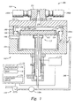
- Figure 2 is an enlarged, partial cross-sectional view of the gas distribution assembly 130.
- Figure 3 is a top cross-sectional view of the gas delivery assembly 130 along lines 3-3 in Figure 2.
- Figure 4 is a schematic illustration of an exemplary flow regime through the gas delivery assembly 130.
- Figure 5A is an enlarged vertical sectional view of one embodiment of the second gas delivery sub-assembly 500.
- Figure 5B is an enlarged vertical sectional view of another embodiment of the second gas delivery sub-assembly 500.
- Figures 6 and 6A are schematic horizontal sectional views of the second gas delivery system 500 along line 6-6 of Figure 5.
- Figure 7A is a cross sectional view of one exemplary design of the thermal plate 180.
- Figures 8A - 8D are schematic representations of an exemplary interconnect structure 800 at different stages of fabrication.
- Figure 9 is a schematic top-view diagram of an exemplary multi-chamber processing system 900 that is adapted to perform the multiple deposition processes disclosed herein.
- FIG. 1 is a schematic, cross-sectional view of a processing system 100 capable of depositing various materials, films, and layers on a work piece surface using multiple deposition techniques.
- the processing system 100 includes a gas distribution assembly 130 disposed on an upper portion of a chamber body 102.
- the chamber body 102 includes a pumping plate 162, a liner 167, a slit valve 108, and a substrate support 112 disposed therein.
- the slit valve 108 is formed within a side wall 104 of the chamber body 102 and allows transfer of a workpiece (not shown) to and from the interior of the chamber body 102 without compromising the fluid-tight seal formed between the gas distribution assembly 130 and the chamber body 102.
- Any conventional workpiece transfer assembly may be used, such as a robotic wafer transfer assembly, for example.
- a robotic wafer transfer assembly is described in the commonly assigned U.S. Patent titled “Multi-chamber Integrated Process System", (U.S. Patent No. 4,951,601), which is incorporated by reference herein.
- the substrate support 112 is mounted to a lift motor 114 to raise and lower the substrate support 112 and a substrate 110 disposed thereon.
- the substrate support 112 may also include a vacuum chuck, an electrostatic chuck, or a clamp ring (not shown) for securing the substrate 110 to the substrate support 112 during processing.
- the substrate support 112 may be heated using an embedded heating element 152, such as a resistive heater, or may be heated using radiant heat, such as heating lamps (not shown) disposed above the substrate support 112.
- a purge ring 122 may be disposed on the substrate support 112 to define a purge channel 124 where a purge gas is provided to prevent deposition on a peripheral portion of the substrate 110.
- the liner 167 is disposed about the support pedestal 112 and circumscribes the interior, vertical surfaces of the chamber body 102.
- the liner 167 is constructed of any process compatible material named above, such as aluminum, and is preferably made of the same material as the chamber body 102.
- a purge channel 168 is formed within the liner 167 and is in fluid communication with a pumping port 117 that extends through a side wall of the chamber body 102.
- a pump system 118 is connectable to the chamber body 102 adjacent the pumping port 117, and helps direct the flow of fluids within the chamber body 102.
- the pumping plate 162 defines an upper surface of the purge channel 168 and controls the flow of fluid between the chamber body 102 and the pumping port 117.
- the pumping plate 162 is an annular member having a plurality of apertures 162A formed therethrough.
- the diameter, number, and position of apertures 162A formed in the pumping plate 162 restrict the flow of gases exiting the chamber body 102 thereby containing the gases in contact with the substrate 110 disposed within the chamber body 102.
- the apertures 162A provide consistent and uniform deposition on the workpiece.
- the diameter, number, and position of apertures 162A are strategically arranged about the pumping plate 162.
- the purge channel 168 has a smaller cross sectional area around the slit valve 108 to accommodate the transfer of the workpieces in and out of the chamber body 102. Accordingly, the size, orientation, and number of apertures 162A must be specifically designed and engineered so that uniform fluid flow about the perimeter and surface of the workpiece is achieved.
- a pump system 118 is connectable to the chamber body 102 at the pumping port 117, and helps direct the flow of fluids within the chamber body 102.
- the pump system 118 evacuates gases from the chamber body 102 and helps maintain a desired pressure or a desired pressure range within the processing system 100.
- the purge channel 168 is coupled to the pump system 118 via a conduit 166 and a throttle valve 118A. The purge channel 168, throttle valve 118A, and pump system 118 work together to control the gas flow within the processing system 100.
- the processing system 100 may further include a remote plasma source (not shown) to clean contaminants or particles formed on interior surfaces thereof.
- a plasma of reactive species may be generated by applying an electric field to a process gas, such as hydrogen, nitrogen, oxygen-containing compounds, fluorine-containing compounds, and mixtures thereof, for example, within the remote plasma source.
- the electric field is generated by a RF or microwave power source (not shown).
- the reactive species are then introduced into the processing system 100 to reactively clean and remove unwanted particles.
- processing system 100 may be integrated into an integrated processing platform, such as an EnduraTM platform available from Applied Materials, Inc. Details of the EnduraTM platform are described in commonly assigned U. S. Patent Application Serial No. 09/451,628, entitled “Integrated Modular Processing Platform", filed on November 30, 1999, which is incorporated by reference herein.
- the gas distribution assembly 130 includes a head assembly 131 and a thermal plate 180 disposed on a chamber lid 132, each having at least a portion of an expanding conduit 134 formed therethrough.
- a lower surface 160 of the lid 132 includes a gradual, tapering slope/recess that extends from a central portion thereof, adjacent the expanding conduit 134, to a peripheral portion thereof.
- the recess formed on the lower surface 160 is sized and shaped to substantially cover the substrate 110 disposed below. It is believed that the tapered lower surface 160 provides a more uniform deposition of the gas across the surface of the substrate 110 because the surface so as to provide a more uniform velocity, delivering a more uniform concentration of the gas across the surface of the substrate 110.
- Figure 2 shows an enlarged, partial cross-sectional view of the gas distribution assembly 130.
- the expanding conduit 134 including an inner diameter 134A that gradually increases from an upper portion 237 thereof to a lower portion 235 thereof.
- the expanding conduit 134 may include one or more tapered inner surfaces, such as a straight tapered surface, a concave surface, a convex surface, or combinations thereof.
- the expanding conduit 134 may also include sections of one or more tapered inner surfaces, such as a first tapered portion and a second non-tapered portion, for example.
- the inner diameter 134A of the expanding conduit 134 is a straight tapered surface that gradually increases from the upper portion 237 thereof to the lower portion 235 thereof.
- the lower portion 235 of the expanding conduit 234 is adjacent the lower surface 160 of the chamber lid 132, and is chamfered/smoothed at a lower edge 238 thereof to minimize stagnation in the gas flow.
- the inner diameter 134A may be between about 0.2 inches and about 1.0 inches at the upper portion 237 and between about 0.5 inches and about 3.0 inches at the lower portion 235. These dimensions are provided for illustrative purpose only, and are known to accommodate a total gas flow between about 500 sccm and about 3,000 sccm. Of course, the specific dimensions can be modified to accommodate any gas flow therethrough.
- the gas distribution assembly 130 also includes at least one first gas delivery sub-assembly 200 and at least one second gas delivery sub-assembly 500 disposed about the head assembly 131. Both gas delivery sub-assemblies 200, 500 are in fluid communication with the expanding conduit 134.
- the first gas delivery system 200 includes at least two high speed actuating valves (two are shown 140A, 140B), to regulate the flow of gases from their respective sources (not shown) into the expanding conduit 134.
- the second gas delivery system 500 is disposed proximate the lower portion 235 of the expanding conduit 134, and is described in more detail below with reference to Figure 5.
- each valve 140A, 140B has two or more ports, and is adapted to provide simultaneous gas flows and/or separate/alternating gas flows to the expanding conduit 134, depending on the mode of deposition.
- the valves 140A, 140B are three-way valves, each coupled to a separate reactant gas source (not shown), and to a common purge gas source (also not shown).
- a carrier gas may be required to deliver one or more reactant gases. When this occurs, the same gas may be used as both the carrier gas and the purge gas.
- Suitable purge/carrier gases include hydrogen, nitrogen, helium, argon, and combinations thereof.
- the valves 140A, 140B precisely and repeatedly deliver short pulses of one or more compounds into the chamber body 102.
- the valves 140A, 140B may be any type of valve capable of reliably, repeatedly, and precisely metering the desired precursors at the desired rate of introduction.
- the on/off cycles or pulses of the valves 140A, 140B are less than about 100 msec. In some cases, dosing may be as fast as 1-2 milliseconds (msec).
- the valves 140A, 140B may be electronically controlled (EC) valves, such as those commercially available from Fujikin of Japan as part number FR-21-6.35 UGF ⁇ APD.
- EC electronically controlled
- each valve 140A, 140B is in fluid communication with the expanding conduit 134 via a delivery conduit 250A, 250B.
- the delivery conduits 250A, 250B may be machined as part of the valves 140A, 140B or the delivery conduits 250A, 250B may be manufactured as separate parts and assembled to the valves 140A, 140B.
- the length of the delivery conduits 250A, 250B are minimized to place the valves 140A, 140B in close proximity to the expanding conduit 134, reducing any unnecessary volume between the valves 140A, 140B and the expanding conduit 134. The proximity provides better control and operability during deposition.
- Figure 3 is a top cross-sectional view of the gas delivery assembly 130 along lines 3-3 in Figure 2.
- the delivery conduits 250A, 250B are positioned tangentially to expanding conduit 134.
- a gas flowing through the delivery conduits 250A, 250B initially flows in a circular direction as shown by arrows 310A, 310B.
- Providing gas tangentially produces a circular, laminar flow through the expanding conduit 234, resulting in an improved flow distribution across the substrate surface 110 and an improved purge of the inner surface of the expanding conduit 134.
- a turbulent flow may not uniformly flow within the expanding conduit 134 and may create areas within the expanding conduit 134 where there is no gas flow.
- FIG 4 is a schematic illustration of an exemplary flow regime through the gas delivery assembly 130.
- the delivery conduits 250A, 250B are positioned in a relationship (+ ⁇ , - ⁇ ) to a longitudinal axis 290 of the expanding conduit 134.
- the gas flows through the delivery conduits 250A, 250B into the inner wall 134A of the expanding conduit 134.
- the contact with the inner wall of the expanding conduit 134 slows the velocity of the gas, reducing the likelihood of blowing off reactants previously adsorbed/absorbed on the surface of the substrate 110.
- An inner diameter of the gas conduits 250A, 250B may also be increased to further reduce the velocity of the gas flow prior to entry into the expanding conduit 134.
- the "vortex" flow 402A, 402B provides superior mixing of the gases, if desired, and provides an efficient purge or sweep of the inner surface of the expanding conduit 134, whereas, the substantially vertical flow allows better deposition on the substrate surface 110.
- the expanding conduit 134 is mirror polished to help produce or encourage the laminar flow of gases therethrough.
- a sudden adiabatic expansion of a gas delivered through the delivery conduits 250A, 250B into the expanding conduit 134 may result in a temperature drop that may cause condensation of the gas and formation of particles.
- the gradually increasing inner diameter 134A of the expanding conduit 134 and the orientation of the delivery conduits 250A, 250B allows less of an adiabatic expansion of a gas through the expanding conduit 134. Therefore, the gas temperature is more easily controlled, preventing gas decomposition, deposition, and condensation on the chamber lid 132.
- the gas temperature may be controlled by controlling the temperature of the chamber lid 132.
- the chamber lid 132 may include cooling elements and/or heating elements (not shown) depending on the particular deposition process and compounds being delivered therethrough.
- one or more water channels may be formed in the chamber lid 132.
- heating elements may be embedded or may surround components of the chamber lid 132.
- the lid 132 may include both heating and cooling channels or elements to heat and/or cool various portions of the lid 132. For example, a central portion of the lid 132, proximate the expanding conduit 134, may be heated while a perimeter portion of the lid 132 may be cooled.
- the radial mixer 510 has an inner wall 515 located between the expanding conduit 134 and the annular mixing channel 520.
- One or more passageways 530 such as nozzles, are formed through the inner wall 515 to allow fluid communication between the mixing channel 520 and the expanding conduit 134.
- the nozzles 530 are disposed radially and are substantially evenly distributed along an outer circumference of the expanding conduit 134.
- the nozzles 530 may be disposed substantially normal to the expanding conduit 134.
- the nozzles 530 may be disposed at an angle relative to normal, such as between about -60° to about +60°.
- the number of nozzles 530 may be twelve; however, other numbers, shapes and/or distributions of nozzles 530 may also be employed.
- FIG. 7A shows a cross sectional view of one exemplary design of the thermal plate 180.
- a recess 181 is formed in both an upper and lower surface of the thermal plate 180 to minimize the surface area of the thermal plate 180 that would otherwise be in contact with the head assembly 131 and the lid 132.
- the reduction of surface area further reduces heat transfer between the components. Consequently, the head assembly 131 remains relatively unaffected by the temperature of the lid 132. Likewise, the lid 132 remains relatively unaffected by the temperature of the head assembly 131. As a result, the temperature of the lid 132 is easier to maintain since less heat/energy is being transferred across the thermal plate 180.
- the processing system 100 may be operated to perform chemical vapor deposition, cyclical layer deposition, atomic layer deposition, digital chemical vapor deposition, and rapid chemical vapor deposition techniques.
- cyclical layer deposition atomic layer deposition
- digital chemical vapor deposition and rapid chemical vapor deposition
- gas phase deposition techniques whereby two or more compounds are sequentially introduced into a reaction zone of a processing chamber to deposit a thin layer of material on a substrate surface.
- the term “compound” is intended to include one or more precursors, oxidants, reductants, reactants, and catalysts, or a combination thereof.
- the term “compound” is also intended to include a grouping of compounds, such as when two or more compounds are introduced in a processing system at the same time.
- a grouping of compounds may include one or more catalysts and one or more precursors.
- the term “compound” is further intended to include one or more precursors, oxidants, reductants, reactants, and catalysts, or a combination thereof in an activated or otherwise energized state, such as by disassociation or ionization.
- a wide variety of semiconductor processing precursors, compounds and reactants may be used.
- Examples may include titanium tetrachloride (TiCl 4 ), tungsten hexafluoride (WF 6 ), tantalum pentachloride (TaCl 5 ), titanium iodide (Til 4 ), titanium bromide (TiBr 4 ), tetrakis(dimethylamido) titanium (TDMAT), pentakis(dimethyl amido) tantalum (PDMAT), tetrakis(diethylamido) titanium (TDEAT), tungsten hexacarbonyl (W(CO) 6 ), tungsten hexachloride (WCl 6 ), tetrakis(diethylamido) titanium (TDEAT), pentakis (ethyl methyl amido) tantalum (PEMAT), pentakis(diethylamido)tantalum (PDEAT), ammonia (NH 3 ), hydrazine (N 2 H 4 ), monomethyl hydrazine (CH 3 N
- Each compound is separated by a time delay/pause to allow each compound to adhere and/or react on the substrate surface.
- the delays are advantageously adjusted to allow adsorption or reaction of a previously pulsed compound.
- a delay may also be adjusted to allow one or more treatment processes to proceed, such as annealing, densification, and nitrification for example.
- a first compound or compound A is dosed/pulsed into the reaction zone followed by a first time delay/pause.
- a second compound or compound B is dosed/pulsed into the reaction zone followed by a second time delay.
- a third compound (C) is dosed/pulsed into the reaction zone followed by a third time delay.
- the quantity of a particular compound within each pulse may vary over time, depending on the duration of the pulse.
- a particular compound may include a single compound or a mixture/combination of two or more compounds.
- a continuous flow of a particular compound is also contemplated by the present invention as described herein and thus, is not outside the scope thereof.
- the durations for each pulse/dose are variable and may be adjusted to accommodate, for example, the volume capacity of the processing chamber as well as the capabilities of a vacuum system coupled thereto.
- the dose time of a compound may vary according to the flow rate of the compound, the pressure of the compound, the temperature of the compound, the type of dosing valve, the type of control system employed, as well as the ability of the compound to adsorb onto the substrate surface. Dose times may also vary based upon the type of layer being formed and the geometry of the device. In general, a dose time should be long enough to provide a volume of compound sufficient to adsorb/chemisorb onto substantially the entire surface of the substrate and form a layer of the desired thickness of the compound thereon.
- the processing system 100 will be further described below, in operation, as it can be employed to deposit, in-situ , a barrier layer by cyclical layer deposition (CLD) and an adhesion layer by chemical vapor deposition (CVD).
- CLD cyclical layer deposition
- CVD chemical vapor deposition
- metal-containing films such as aluminum, copper, titanium, tantalum, tungsten, nitrides thereof, oxides thereof, and combinations thereof may be deposited within the processing system 100.
- the barrier layer may include one or more refractory metals, such as tungsten, titanium, and tantalum, for example.
- the barrier layer may also include one or more refractory metal nitrides, such as tungsten nitride, titanium nitride, and tantalum nitride, for example.
- the barrier layer may further include a ternary material, such as titanium silicon nitride and tantalum silicon nitride, for example.
- the adhesion layer may include aluminum, copper, tungsten, alloys thereof, nitrides thereof, oxides thereof, and alloys thereof, for example.
- one or more metal-containing precursors and one or more reductants are cyclically introduced into the expanding conduit 134 via the valves 140A, 140B, while a carrier or purge gas flows into the expanding conduit 134 via the nozzles 530.
- the carrier or purge gas may be introduced as a continuous flow or as one or more separately initiated flows, such as one or more pulses for example, between each pulse of the deposition compounds.
- each deposition compound may utilize its own carrier or purge gas, whether continuous and/or pulsed.
- a single carrier or purge gas, whether continuous and/or pulsed, may be all that is needed.
- Each carrier or purge gas may contain a single gas or a mixture/combination of two or more gases.
- the gases may be non-reactive with the compounds introduced for the purpose of deposition on the wafer.
- the gases may be reactive with one another or reactive with one or more of the compounds introduced for the purpose of deposition to form intermediate compounds, reactive compounds, and/or non-depositing compounds, for example.
- Exemplary gases include argon, helium, nitrogen, oxygen, and hydrogen.
- one or more metal-containing precursors are introduced into the expanding conduit 134 via the nozzles 530, while a purge gas flows into the expanding conduit 134 via the valves 140A, 140B.
- a suitable purge gas may include hydrogen, helium, nitrogen, argon, or a combination thereof, for example.
- the purge gas flows into the expanding conduit 134 via the valves 140A, 140B or via the nozzles 530, whichever is not in use for the precursor gases, to prevent back flow, control deposition temperature, assist mixing of the deposition gases, and assist distribution of the deposition gases.
- the purge gas provides a positive pressure within the gas delivery assembly 130 to direct the deposition gases towards a lower pressure, and creates a pressure differential that isolates the valves 140A, 140B from the nozzles 530 during deposition.
- deposition gas includes one or more precursors, reductants, reactants, and catalysts. Each "deposition gas” may be a single compound or a mixture/combination of two or more compounds.
- a substrate 110 to be processed is positioned on the substrate support 112 within the chamber body 102.
- argon gas is flowed into the processing system 100 via the nozzles 530 and the valves 140A, 140B to stabilize the temperature and pressure therein.
- One or more pulses of a tantalum-containing compound are then alternately introduced into the expanding conduit 134 via the first valve 140A with one or more pulses of a nitrogen-containing compound, introduced into the expanding conduit 134 via the second valve 140B.
- a purge gas such as argon for example, is flowed through the mixing channel 520 into the expanding conduit 134.
- the time between pulses of the tantalum-containing compound and the nitrogen-containing compound may be about 0.5 seconds or less, about 0.1 seconds or less, or about 0.07 seconds or less.
- This process forms a tantalum nitride layer having a thickness between about 0.5 ⁇ and about 1.0 ⁇ per cycle.
- the alternating sequence is then repeated until a desired thickness is achieved, such as 1,000 ⁇ or less, preferably about 20 ⁇ or less, and more preferably about 10 ⁇ .
- the tantalum-containing compound and the nitrogen-containing compound flow through the expanding conduit 134 within the vortex flow pattern 402, resembling a sweeping action across the inner surface of the expanding conduit 134.
- the vortex flow pattern 402 dissipates to a downward flow 404 toward the surface of the substrate 110.
- the gases then flow across the bottom surface 160 of the chamber lid 132 and across the surface of the substrate 110.
- the bottom surface 160 of the chamber lid 132 which is downwardly sloping, helps reduce the variation of the velocity of the gas flow across the surface of the substrate 110.
- the gases flow from the chamber body 102 into the pump system 118 via the apertures 162A formed in the pumping plate 162.
- the argon purge gas is introduced from the second gas delivery sub-assembly 500 at a flow rate between about 100 sccm and about 1000 sccm, preferably, between about 100 sccm and about 400 sccm.
- the argon purge gas flows along the inner surfaces of the expanding conduit 134 to prevent condensation or deposition thereon.
- the purge gas also shields or isolates the deposition gases from the temperature of the walls of the expanding conduit 134 and the chamber lid 132, allowing better control of the deposition conditions.
- the isolation of the deposition gases from the walls of the expanding conduit 134 and the chamber lid 132 also helps prevent decomposition of the precursor gases if the walls are at a high temperature.
- the purge gas helps to mix the tantalum-containing compound and the nitrogen-containing compound passing through the expanding conduit 134. Still further, the purge gas prevents back-flow of the deposition gases into the mixing channel 520.
- tantalum-containing compounds include: t-butylimino tris(diethylamino) tantalum (TBTDET); pentakis (ethylmethylamino); tantalum (PEMAT); pentakis (dimethylamino) tantalum (PDMAT); pentakis (diethylamino) tantalum (PDEAT); t-butylimino tris(diethyl methylamino) tantalum (TBTMET); t-butylimino tris(dimethyl amino) tantalum (TBTDMT); bis(cyclopentadienyl) tantalum trihydride ((Cp)2TaH3); bis(methylcyclopentadienyl) tantalum trihydride ((CpMe)2TaH3); derivatives thereof; and combinations thereof.
- TBTDET t-butylimino tris(diethylamino) tantalum
- PEMAT pentakis (ethylmethyl
- some exemplary nitrogen-containing compounds include: ammonia; hydrazine; methylhydrazine; dimethylhydrazine; t-butylhydrazine; phenylhydrazine; azoisobutane; ethylazide; derivatives thereof; and combinations thereof.
- these compounds or any other suitable compound not listed above may be a solid, liquid, or gas at room temperature.
- PDMAT is a solid at room temperature
- TBTDET is a liquid at room temperature.
- a carrier gas such as argon, helium, nitrogen, hydrogen, or a mixture thereof, may also be used to help deliver the compound into the processing chamber, as is commonly known in the art.
- PDMAT pentadimethyl-amino tantalum
- ammonia is described below.
- PDMAT is a preferred tantalum-containing compound for a number of reasons.
- PDMAT is relatively stable, and has a vapor pressure which makes it easy to deliver.
- PDMAT may also be produced with a low halide content, such as less than 100 ppm, and may even be produced with a halide content of less than 30 ppm or even less than 5 ppm.
- an inert/purge gas such as argon is first introduced into the expanding conduit 134 via the valves 140A, 140B and the nozzles 530 to stabilize the pressure and temperature within the chamber body 102.
- the argon gas will continuously flow through the valves 140A, 140B during the deposition process such that only the argon gas flows between pulses of PDMAT and ammonia. Likewise, the argon continuously flows through the nozzles 530 during the deposition process.
- a first pulse of PDMAT is provided to the expanding conduit 134 via the first valves 140A at a flow rate between about between about 100 sccm and about 400 sccm, with a pulse time of about 0.6 seconds or less.
- a pulse of ammonia is then provided to the expanding conduit 134 via the second valve 140B at a flow rate between about 200 sccm and about 600 sccm, with a pulse time of about 0.6 seconds or less.
- a purge gas flows through the valves 140A, 140B while the deposition gases flow through the nozzles 530 into the expanding conduit 134.
- the adhesion layer may contain any type of material that are known in the art or yet to be discovered. However, for simplicity and ease of description, the invention will be further described in reference to depositing an adhesion layer containing aluminum.
- Useful aluminum-containing precursors include dimethyl aluminum hydride (DMAH) and trimethylaluminum (TMA), for example. While the adhesion layer may be deposited under various conditions, a typical process involves a wafer temperature between about 150°C and about 300°C at a pressure of about 1 Torr to about 80 Torr. The deposition rate is usually about 20 ⁇ /sec to about 150 ⁇ /sec.
- DMAH dimethyl aluminum hydride
- TMA trimethylaluminum
- DMAH flows through the first gas inlet 525 into the mixing channel 520 at a rate between about 100 sccm and about 2,000 sccm while a reducing gas, such as hydrogen for example, flows through the second gas inlet 526 into the mixing channel 520 at a rate between about 100 sccm and about 2,000 sccm.
- a reducing gas such as hydrogen for example
- Figures 8A - 8D are schematic representations of an exemplary interconnect structure 800 at different stages of fabrication and are presented to illustrate an exemplary fabrication process according to embodiments described herein.
- Figure 8A shows an underlying metal layer 810 having a dielectric layer 812 formed thereon.
- the underlying metal layer 810 may contain any conductive metal such as aluminum, copper, tungsten, or combinations thereof, for example, and may form part of an interconnect feature such as a plug, via, contact, line, wire, and may also be part of a metal gate electrode.
- Figure 8B shows a barrier layer 830 at least partially deposited on the underlying metal layer 810.
- Figure 8C shows an adhesion layer 840 at least partially deposited on the barrier layer 830
- Figure 8D shows a bulk metal layer 850 at least partially deposited on the adhesion layer 840.
- the dielectric layer 812 may be any dielectric material including a low k dielectric material (k ⁇ 4.0), whether presently known or yet to be discovered.
- the dielectric layer 812 may be a silicon oxide or a carbon doped silicon oxide, for example.
- the dielectric layer 812 has been etched to form a feature 814 therein using conventional and well-known techniques.
- the feature 814 may be a plug, via, contact, line, wire, or any other interconnect component.
- the feature 814 has vertical sidewalls 816 and a floor 818, having an aspect ratio of about 4:1 or greater, such as about 6:1.
- the floor 818 exposes at least a portion of the lower level metal interconnect 810.
- the barrier layer 830 is conformally deposited on the floor 818 as well as the side walls 816 of the feature 814 using a CLD technique.
- the barrier layer 830 includes tantalum nitride and is deposited as described above within the processing system 100.
- the chamber pressure is increased to about 140 mTorr, and a processing gas consisting essentially of hydrogen and helium is introduced into the processing region.
- the processing gas contains about 5% hydrogen and about 95% helium.
- the hydrogen plasma is generated by applying between about 50 watts and about 500 watts power. The hydrogen plasma is maintained for about 10 seconds to about 300 seconds.
- An adhesion layer 840 is then deposited on the barrier layer 830 using a CVD technique.
- the adhesion layer 840 may include aluminum deposited according to embodiments described above.
- the substrate 800 may then be transferred into a separate processing chamber to complete the metallization by depositing the metal layer 850 shown in Figure 8D.
- a copper electrolyte solution and copper electroplating technique is described in commonly assigned U.S. Patent No. 6,113,771, entitled “Electrodeposition Chemistry", which is incorporated by reference herein.
- the electroplating bath has a copper concentration greater than about 0.7M, a copper sulfate concentration of about 0.85, and a pH of about 1.75.
- the electroplating bath may also contain various additives as is well known in the art.
- the temperature of the bath is between about 15°C and about 25°C.
- the bias is between about -15 volts to about 15 volts. In one aspect, the positive bias ranges from about 0.1 volts to about 10 volts and the negatives bias ranges from about - 0.1 to about -10 volts.
- an anneal treatment may be performed following the metal layer 850 deposition whereby the substrate is subjected to a temperature between about 100°C and about 400°C for about 10 minutes to about 1 hour, preferably about 30 minutes.
- a carrier/purge gas such as helium, hydrogen, nitrogen, or a mixture thereof is introduced at a rate of about 100 sccm to about 10,000 sccm.
- the chamber pressure is maintained between about 2 Torr and about 10 Torr.
- the RF power is about 200 W to about 1,000 W at a frequency of about 13.56 MHz, and the preferable substrate spacing is between about 300 mils and about 800 mils.
- the top portion of the resulting structure may be planarized.
- a chemical mechanical polishing (CMP) apparatus may be used, such as the MirraTM System available from Applied Materials, Santa Clara, California, for example.
- CMP chemical mechanical polishing
- the intermediate surfaces of the structure may be planarized between the deposition of the subsequent layers described above.
- FIG 9 is a schematic top-view diagram of an exemplary multi-chamber processing system 900 that may be adapted to perform the fabrication sequence described above.
- a processing system 900 may be an Endura system, commercially available from Applied Materials, Inc., of Santa Clara, California.
- a similar multi-chamber processing system is disclosed in U.S. Patent No. 5,186,718, entitled “Stage Vacuum Wafer Processing System and Method,” issued on February 16, 1993, which is incorporated by reference herein.
- the processing chambers 932, 934, 936 and 938 are a dual CLD and CVD processing system, as described above, adapted to deposit a barrier layer in a CLD mode followed by depositing an adhesion layer in a CVD mode.
- the processing chambers 912 and 914 may be a physical vapor deposition chamber, a chemical vapor deposition chamber, or a cyclical deposition chamber adapted to deposit a dielectric layer.
- the processing chambers 916 and 918 may be etch chambers outfitted to etch apertures or openings for interconnect features. This one particular arrangement of the system 900 is provided for illustrative purposes only and should not be used to limit the scope of the invention.
Landscapes
- Chemical & Material Sciences (AREA)
- General Chemical & Material Sciences (AREA)
- Chemical Kinetics & Catalysis (AREA)
- Engineering & Computer Science (AREA)
- Materials Engineering (AREA)
- Mechanical Engineering (AREA)
- Metallurgy (AREA)
- Organic Chemistry (AREA)
- Physics & Mathematics (AREA)
- Fluid Mechanics (AREA)
- Chemical Vapour Deposition (AREA)
- Electrodes Of Semiconductors (AREA)
- Internal Circuitry In Semiconductor Integrated Circuit Devices (AREA)
Abstract
Description
- Embodiments of the invention generally relate to an apparatus and method for performing multiple vapor deposition processes in-situ. More particularly, embodiments of the invention relate to an improved gas delivery apparatus and method for depositing films in-situ using both cyclical layer and chemical vapor deposition techniques.
- Sub-quarter micron multilevel metallization is one of the key technologies for the next generation of very large scale integration (VLSI). The multilevel interconnects that lie at the heart of this technology possess high aspect ratio features, including contacts, vias, lines, or other apertures. Reliable formation of these features is very important to the success of VLSI and to the continued effort to increase quality and circuit density on individual substrates. Therefore, there is a great amount of ongoing effort being directed to the formation of void-free features having high aspect ratios of 4:1 (height:width) or greater.
- Copper has recently become a choice metal for filling VLSI features, such as sub-micron high aspect ratio, interconnect features, because copper and its alloys have lower resistivities than aluminum. However, copper and its alloys have a propensity to diffuse into surrounding materials such as silicon oxide, silicon, and other dielectric materials for example, causing an increase in the contact resistance of the circuit. Copper and its alloys also have a propensity to diffuse into surrounding elements such as transistor gates, capacitor dielectrics, transistor wells, transistor channels, electrical barrier regions, interconnects, among other known elements of integrated circuits. Barrier layers are, therefore, deposited prior to copper metallization to prevent or impede the diffusion of copper atoms.
- A typical sequence for forming an interconnect includes depositing one or more non-conductive layers, etching at least one of the layer(s) to form one or more features therein, depositing a barrier layer in the feature(s) and depositing one or more conductive layers, such as copper, to fill the feature. The barrier layer typically includes a refractory metal such as tungsten, titanium, tantalum, and nitrides thereof. Of this group, tantalum nitride is one of the most desirable elements for use as a barrier layer because it has one of the lowest resistivities of the refractory metal nitrides and makes a good adhesion layer for copper metallization. A refractory metal nitride layer, such as tantalum nitride, is typically deposited using conventional deposition techniques, such as physical vapor deposition (PVD) and chemical vapor deposition (CVD).
- Conventional deposition processes have difficulty forming interconnect structures because these processes have problems filling sub-micron structures where the aspect ratio exceeds 4:1, and particularly where the aspect ratio exceeds 10:1. Often, the barrier layer bridges the opening of a narrow feature, resulting in the formation of one or more voids or discontinuities within the feature. Since voids increase the resistance and reduce the electromigration resistance of the feature, features having voids make poor and unreliable electrical contacts.
- Atomic layer deposition (ALD) is one deposition technique being explored to deposit materials, such as a barrier layer, over features having high aspect ratios. ALD involves the sequential introduction of separate pulses of a first reactant and a second reactant, resulting in a self-limiting absorption of monolayers of material on the substrate surface. The reactants are sequentially introduced until a desired thickness of the deposited material is deposited. A pulse of a purge gas and/or a pump evacuation between the pulses of the reactants serves to reduce the likelihood of gas phase reactions of the reactants due to excess amounts of the reactants remaining in the chamber.
- Often within a typical fabrication sequence, a processed wafer is transferred between various processing chambers, consuming valuable processing time. Sometimes, the process wafer is subjected to a vacuum break between processing chambers and thus, the substrate is exposed to ambient conditions which, among other things, leads to oxidation of the substrate surface. Like voids, metal oxides increase the resistance of the interconnect and reduce the electromigration resistance of vias and small features. Metal oxides also become a source of particle problems and reduce the reliability of the overall circuit. Metal oxides may also interfere with subsequent deposition processes by creating voids that promote uneven distribution of a subsequent depositing layer.
- There is a need, therefore, for a new method and apparatus for depositing multiple layers of material in-situ using multiple deposition techniques. Such a new method and apparatus would eliminate the need to transfer substrates between various processing chambers, and would reduce the likelihood of void formation.
- An apparatus capable of performing multiple deposition processes is provided. In one embodiment, the apparatus includes a chamber body and a gas distribution assembly disposed on the chamber body. In one aspect of this embodiment, the gas distribution assembly includes a gas conduit in fluid communication with the chamber body, two or more isolated gas inlets equipped with one or more high speed actuating valves in fluid communication with the gas conduit, and a mixing channel in fluid communication with the gas conduit. The valves are adapted to alternately pulse two or more compounds into the gas conduit, and the mixing channel is adapted to deliver a continuous flow of one or more compounds into the gas conduit.
- In another aspect of this embodiment, the gas distribution assembly comprises a gas conduit in fluid communication with the chamber body, at least two separate flow paths in fluid communication with the gas conduit at a first end thereof, and at least one annular mixing channel disposed about the gas conduit at a second end thereof. Each isolated flow path comprises one or more high speed actuating valves, and the mixing channel is in fluid communication with the gas conduit via a plurality of nozzles formed therethrough. The flow paths are isolated from the mixing channel by a pressure differential created within the gas distribution assembly.
- A method for depositing multiple layers on a substrate surface by performing multiple deposition processes within a single processing chamber is also provided. In one aspect, the method comprises positioning a substrate surface to be processed within a chamber body, delivering two or more compounds into the chamber body utilizing a gas distribution assembly disposed on the chamber body to deposit a film comprising a first material, and then delivering two or more compounds into the chamber body utilizing a gas distribution assembly disposed on the chamber body to deposit a film comprising a second material. The gas distribution assembly comprises a gas conduit in fluid communication with the chamber body, at least two isolated flow paths in fluid communication with the gas conduit at a first end thereof, and at least one annular mixing channel disposed about the gas conduit at a second end thereof. Each isolated flow path comprising one or more high speed actuating valves that are adapted to alternately pulse the two or more compounds into the gas conduit. The mixing channel is in fluid communication with the gas conduit via a plurality of nozzles formed therethrough, and is adapted to deliver a continuous flow of the two or more compounds into the gas conduit.
- So that the manner in which the above recited features of the present invention are attained and can be understood in detail, a more particular description of the invention, briefly summarized above, may be had by reference to the embodiments thereof which are illustrated in the appended drawings. It is to be noted, however, that the appended drawings illustrate only typical embodiments of this invention and therefore, are not to be considered limiting of its scope, for the invention may admit to other equally effective embodiments.
- Figure 1 is a schematic, cross-sectional view of a
processing system 100 capable of performing both a cyclical layer deposition process and a chemical vapor deposition process according to embodiments of the invention. - Figure 2 is an enlarged, partial cross-sectional view of the
gas distribution assembly 130. - Figure 3 is a top cross-sectional view of the
gas delivery assembly 130 along lines 3-3 in Figure 2. - Figure 4 is a schematic illustration of an exemplary flow regime through the
gas delivery assembly 130. - Figure 5A is an enlarged vertical sectional view of one embodiment of the second
gas delivery sub-assembly 500. - Figure 5B is an enlarged vertical sectional view of another embodiment of the second
gas delivery sub-assembly 500. - Figures 6 and 6A are schematic horizontal sectional views of the second
gas delivery system 500 along line 6-6 of Figure 5. - Figure 7 is an isometric view of an exemplary
thermal plate 180 suitable for embodiments of theprocessing system 100 described herein. - Figure 7A is a cross sectional view of one exemplary design of the
thermal plate 180. - Figures 8A - 8D are schematic representations of an exemplary interconnect structure 800 at different stages of fabrication.
- Figure 9 is a schematic top-view diagram of an exemplary multi-chamber processing system 900 that is adapted to perform the multiple deposition processes disclosed herein.
- Figure 1 is a schematic, cross-sectional view of a
processing system 100 capable of depositing various materials, films, and layers on a work piece surface using multiple deposition techniques. Theprocessing system 100 includes agas distribution assembly 130 disposed on an upper portion of achamber body 102. Thechamber body 102 includes apumping plate 162, a liner 167, aslit valve 108, and asubstrate support 112 disposed therein. Theslit valve 108 is formed within aside wall 104 of thechamber body 102 and allows transfer of a workpiece (not shown) to and from the interior of thechamber body 102 without compromising the fluid-tight seal formed between thegas distribution assembly 130 and thechamber body 102. Any conventional workpiece transfer assembly (not shown) may be used, such as a robotic wafer transfer assembly, for example. One example of a conventional robotic wafer transfer assembly is described in the commonly assigned U.S. Patent titled "Multi-chamber Integrated Process System", (U.S. Patent No. 4,951,601), which is incorporated by reference herein. - The
substrate support 112 is mounted to alift motor 114 to raise and lower thesubstrate support 112 and asubstrate 110 disposed thereon. Thesubstrate support 112 may also include a vacuum chuck, an electrostatic chuck, or a clamp ring (not shown) for securing thesubstrate 110 to thesubstrate support 112 during processing. Thesubstrate support 112 may be heated using an embeddedheating element 152, such as a resistive heater, or may be heated using radiant heat, such as heating lamps (not shown) disposed above thesubstrate support 112. Apurge ring 122 may be disposed on thesubstrate support 112 to define apurge channel 124 where a purge gas is provided to prevent deposition on a peripheral portion of thesubstrate 110. - The liner 167 is disposed about the
support pedestal 112 and circumscribes the interior, vertical surfaces of thechamber body 102. The liner 167 is constructed of any process compatible material named above, such as aluminum, and is preferably made of the same material as thechamber body 102. Apurge channel 168 is formed within the liner 167 and is in fluid communication with a pumpingport 117 that extends through a side wall of thechamber body 102. Apump system 118 is connectable to thechamber body 102 adjacent the pumpingport 117, and helps direct the flow of fluids within thechamber body 102. - The
pumping plate 162 defines an upper surface of thepurge channel 168 and controls the flow of fluid between thechamber body 102 and the pumpingport 117. Thepumping plate 162 is an annular member having a plurality ofapertures 162A formed therethrough. The diameter, number, and position ofapertures 162A formed in thepumping plate 162 restrict the flow of gases exiting thechamber body 102 thereby containing the gases in contact with thesubstrate 110 disposed within thechamber body 102. Theapertures 162A provide consistent and uniform deposition on the workpiece. - Since the volume of the
purge channel 168 is not consistent around the perimeter of thechamber body 102, the diameter, number, and position ofapertures 162A are strategically arranged about thepumping plate 162. For example, thepurge channel 168 has a smaller cross sectional area around theslit valve 108 to accommodate the transfer of the workpieces in and out of thechamber body 102. Accordingly, the size, orientation, and number ofapertures 162A must be specifically designed and engineered so that uniform fluid flow about the perimeter and surface of the workpiece is achieved. - A
pump system 118 is connectable to thechamber body 102 at the pumpingport 117, and helps direct the flow of fluids within thechamber body 102. Thepump system 118 evacuates gases from thechamber body 102 and helps maintain a desired pressure or a desired pressure range within theprocessing system 100. Thepurge channel 168 is coupled to thepump system 118 via aconduit 166 and athrottle valve 118A. Thepurge channel 168,throttle valve 118A, andpump system 118 work together to control the gas flow within theprocessing system 100. - The
processing system 100 may further include a remote plasma source (not shown) to clean contaminants or particles formed on interior surfaces thereof. A plasma of reactive species may be generated by applying an electric field to a process gas, such as hydrogen, nitrogen, oxygen-containing compounds, fluorine-containing compounds, and mixtures thereof, for example, within the remote plasma source. Typically, the electric field is generated by a RF or microwave power source (not shown). The reactive species are then introduced into theprocessing system 100 to reactively clean and remove unwanted particles. - Furthermore, the
processing system 100 may be integrated into an integrated processing platform, such as an Endura™ platform available from Applied Materials, Inc. Details of the Endura™ platform are described in commonly assigned U. S. Patent Application Serial No. 09/451,628, entitled "Integrated Modular Processing Platform", filed on November 30, 1999, which is incorporated by reference herein. - Still referring to Figure 1, the
gas distribution assembly 130 includes ahead assembly 131 and athermal plate 180 disposed on achamber lid 132, each having at least a portion of an expandingconduit 134 formed therethrough. Alower surface 160 of thelid 132 includes a gradual, tapering slope/recess that extends from a central portion thereof, adjacent the expandingconduit 134, to a peripheral portion thereof. The recess formed on thelower surface 160 is sized and shaped to substantially cover thesubstrate 110 disposed below. It is believed that the taperedlower surface 160 provides a more uniform deposition of the gas across the surface of thesubstrate 110 because the surface so as to provide a more uniform velocity, delivering a more uniform concentration of the gas across the surface of thesubstrate 110. - Figure 2 shows an enlarged, partial cross-sectional view of the
gas distribution assembly 130. The expandingconduit 134 including aninner diameter 134A that gradually increases from anupper portion 237 thereof to alower portion 235 thereof. The expandingconduit 134 may include one or more tapered inner surfaces, such as a straight tapered surface, a concave surface, a convex surface, or combinations thereof. The expandingconduit 134 may also include sections of one or more tapered inner surfaces, such as a first tapered portion and a second non-tapered portion, for example. In one aspect, theinner diameter 134A of the expandingconduit 134 is a straight tapered surface that gradually increases from theupper portion 237 thereof to thelower portion 235 thereof. Thelower portion 235 of the expandingconduit 234 is adjacent thelower surface 160 of thechamber lid 132, and is chamfered/smoothed at alower edge 238 thereof to minimize stagnation in the gas flow. In one aspect, theinner diameter 134A may be between about 0.2 inches and about 1.0 inches at theupper portion 237 and between about 0.5 inches and about 3.0 inches at thelower portion 235. These dimensions are provided for illustrative purpose only, and are known to accommodate a total gas flow between about 500 sccm and about 3,000 sccm. Of course, the specific dimensions can be modified to accommodate any gas flow therethrough. - The
gas distribution assembly 130 also includes at least one firstgas delivery sub-assembly 200 and at least one secondgas delivery sub-assembly 500 disposed about thehead assembly 131. Bothgas delivery sub-assemblies conduit 134. The firstgas delivery system 200 includes at least two high speed actuating valves (two are shown 140A, 140B), to regulate the flow of gases from their respective sources (not shown) into the expandingconduit 134. The secondgas delivery system 500 is disposed proximate thelower portion 235 of the expandingconduit 134, and is described in more detail below with reference to Figure 5. - Regarding the first
gas delivery system 200 in more detail, eachvalve conduit 134, depending on the mode of deposition. In one aspect, thevalves - The
valves chamber body 102. Thevalves valves valves - As shown in Figure 2, each
valve conduit 134 via adelivery conduit delivery conduits valves delivery conduits valves delivery conduits valves conduit 134, reducing any unnecessary volume between thevalves conduit 134. The proximity provides better control and operability during deposition. - Figure 3 is a top cross-sectional view of the
gas delivery assembly 130 along lines 3-3 in Figure 2. Thedelivery conduits conduit 134. During use, a gas flowing through thedelivery conduits arrows conduit 234, resulting in an improved flow distribution across thesubstrate surface 110 and an improved purge of the inner surface of the expandingconduit 134. In comparison, a turbulent flow may not uniformly flow within the expandingconduit 134 and may create areas within the expandingconduit 134 where there is no gas flow. - Figure 4 is a schematic illustration of an exemplary flow regime through the
gas delivery assembly 130. As shown, thedelivery conduits longitudinal axis 290 of the expandingconduit 134. Eachdelivery conduit longitudinal axis 290 or positioned at an angle (in which 0° < +β < 90° or 0° < -β < 90°) relative to thelongitudinal axis 290. Regardless of the relationship (+β, -β), the gas flows through thedelivery conduits inner wall 134A of the expandingconduit 134. The contact with the inner wall of the expandingconduit 134 slows the velocity of the gas, reducing the likelihood of blowing off reactants previously adsorbed/absorbed on the surface of thesubstrate 110. An inner diameter of thegas conduits conduit 134. - Although the exact flow pattern through the expanding
conduit 134 is not known, it is believed that the initial circular,laminar flow arrows conduit 134. Adistance 410 between thedelivery conduits substrate 110 is designed such that the "vortex"flow flow conduit 134, whereas, the substantially vertical flow allows better deposition on thesubstrate surface 110. In one aspect, the expandingconduit 134 is mirror polished to help produce or encourage the laminar flow of gases therethrough. - A sudden adiabatic expansion of a gas delivered through the
delivery conduits conduit 134 may result in a temperature drop that may cause condensation of the gas and formation of particles. Not wishing to be bound by theory, it is believed that the gradually increasinginner diameter 134A of the expandingconduit 134 and the orientation of thedelivery conduits conduit 134. Therefore, the gas temperature is more easily controlled, preventing gas decomposition, deposition, and condensation on thechamber lid 132. - The gas temperature may be controlled by controlling the temperature of the
chamber lid 132. Thechamber lid 132 may include cooling elements and/or heating elements (not shown) depending on the particular deposition process and compounds being delivered therethrough. In one aspect, one or more water channels may be formed in thechamber lid 132. In another aspect, heating elements may be embedded or may surround components of thechamber lid 132. In another aspect, thelid 132 may include both heating and cooling channels or elements to heat and/or cool various portions of thelid 132. For example, a central portion of thelid 132, proximate the expandingconduit 134, may be heated while a perimeter portion of thelid 132 may be cooled. - Figure 5A shows an enlarged vertical sectional view of the second
gas delivery sub-assembly 500. The secondgas delivery sub-assembly 500 includes aradial mixer 510 having a mixingchannel 520 formed therethrough. The mixingchannel 520 is annular and is formed concentric with the expandingconduit 134. A volume of the mixingchannel 520 depends on many factors, such as the precursor gases employed, the size of thechamber body 102, the size of thesubstrate 110 to be processed, the volume and dimensions of the expandingconduit 134, as well as the operating temperature, pressure, and flow rate of the gases used during deposition. - The
radial mixer 510 has aninner wall 515 located between the expandingconduit 134 and theannular mixing channel 520. One ormore passageways 530, such as nozzles, are formed through theinner wall 515 to allow fluid communication between the mixingchannel 520 and the expandingconduit 134. Thenozzles 530 are disposed radially and are substantially evenly distributed along an outer circumference of the expandingconduit 134. Thenozzles 530 may be disposed substantially normal to the expandingconduit 134. Alternatively, thenozzles 530 may be disposed at an angle relative to normal, such as between about -60° to about +60°. In one aspect, the number ofnozzles 530 may be twelve; however, other numbers, shapes and/or distributions ofnozzles 530 may also be employed. - At least one gas inlet (two inlets are shown 525, 526) is in communication with the mixing
channel 520 from outside of theradial mixer 510. Typically, thegas inlets gas inlets annular mixing channel 520 where the gases mix prior to entering the expandingconduit 134 via thenozzles 530. - The
inlets nozzles 530. For instance, theinlets nozzles 530 so that any one of the respective velocities of the gases emerging from any one of thegas inlets channel 520, and a substantially equal flow of gas enters the expandingconduit 134 through thenozzles 530. - Figure 5B shows an enlarged vertical sectional view of another embodiment of the second
gas delivery sub-assembly 500. The secondgas delivery sub-assembly 500 includes a gap orpassageway 555 formed in a lower surface of theinner wall 515. Although now shown, it is contemplated to have bothnozzles 530 and agap 555 formed through theinner wall 515. In one aspect of this embodiment, the height of thegap 555 may be constant across the diameter of theinner wall 515. In another aspect of this embodiment, the height of thegap 555 may vary across the diameter of theinner wall 515 to compensate for the pumping effects created within thechamber 102. For example, the height of thegap 555 nearest the pumpingport 117 may be half the height of thegap 555 opposite the pumpingport 117 to choke off the fluid flow where the pressure differential is the greatest. By changing the height of thegap 555, the fluid dynamics of the gas flowing through the mixingchannel 520 can be better controlled to provide better mixing or better distribution through out the expandingconduit 134 and thechamber body 102. - Figure 6 is a schematic horizontal sectional view of the second
gas delivery system 500 along line 6-6 of Figure 5. Thenozzles 530 are arranged and dimensioned to provide substantial flow resistance to the gas flowing from the mixingchannel 520 to the expandingconduit 134. The substantial resistance to gas flow provided by thenozzles 530 allows a substantially equal rate of flow to be achieved through each of thenozzles 530, providing a full and even flow distribution to thesubstrate 110. - Figure 6A is a schematic horizontal sectional view of an alternative embodiment of the second
gas delivery system 500. In this embodiment, a plurality of tangentially disposednozzles 630 are formed within theinner wall 515 of theradial mixer 510 to provide a directional flow along an inner diameter of the expandingconduit 134. The nozzles are preferably angled in the same direction to provide a clockwise flow pattern of the gases flowing therethrough. The directional flow provides a swirling effect that encourages mixing of the gases and attracts the flowing gases to theinner diameter 134A of the expandingconduit 134, delivering a full distribution of mixed gases to thesubstrate 110. - Figure 7 shows an isometric view of an exemplary insulating
plate 180 suitable for embodiments of theprocessing system 100 described herein. The insulatingplate 180 is an annular member that is disposed about the expandingconduit 134 between thehead assembly 131 and thechamber lid 132. The insulatingplate 180 thermally confines or isolates thehead assembly 131 from thechamber lid 132, and is preferably made from a material, such as stainless steel for example, that has a low heat transfer coefficient. In other words, any material that is not a good conductor is preferred, so as to thermally insulate thehead assembly 131 from the rest of theprocessing system 100, such as thechamber body 102 and thechamber lid 132. As such, better temperature control and better overall operability is achieved. - Figure 7A shows a cross sectional view of one exemplary design of the
thermal plate 180. In this embodiment, arecess 181 is formed in both an upper and lower surface of thethermal plate 180 to minimize the surface area of thethermal plate 180 that would otherwise be in contact with thehead assembly 131 and thelid 132. The reduction of surface area further reduces heat transfer between the components. Consequently, thehead assembly 131 remains relatively unaffected by the temperature of thelid 132. Likewise, thelid 132 remains relatively unaffected by the temperature of thehead assembly 131. As a result, the temperature of thelid 132 is easier to maintain since less heat/energy is being transferred across thethermal plate 180. - Referring again to Figure 1, the
processing system 100 may further include acontroller 170, such as a programmed personal computer, work station computer, or the like, to control processing conditions. For example, thecontroller 170 may be configured to control flow of various process gases, carrier gases and purge gases through thevalves controller 170 includes aprocessor 172 in data communication with memory, such asrandom access memory 174 and ahard disk drive 176. Typically, thecontroller 170 is in communication with at least thepump system 118, thepower source 114, andvalves controller 170 may be configured to be responsible for automated control of other activities used in wafer processing---such as wafer transport, temperature control, chamber evacuation, among other activities, some of which are described elsewhere herein. Anexemplary controller 170 is a chamber/application specific controller, such as a programmable logic computer (PLC) which is described in more detail in the co-pending U.S. Patent Application Serial No. 09/800,881, entitled "Valve Control System For ALD Chamber", filed on March 7, 2001, which is incorporated by reference herein. - The
processing system 100 may be operated to perform chemical vapor deposition, cyclical layer deposition, atomic layer deposition, digital chemical vapor deposition, and rapid chemical vapor deposition techniques. The terms "cyclical layer deposition", "atomic layer deposition", "digital chemical vapor deposition", and "rapid chemical vapor deposition" are used interchangeably herein and refer to gas phase deposition techniques whereby two or more compounds are sequentially introduced into a reaction zone of a processing chamber to deposit a thin layer of material on a substrate surface. - A "substrate surface", as used herein, refers to any substrate surface upon which film processing is performed. For example, a substrate surface may include silicon, silicon oxide, doped silicon, germanium, gallium arsenide, glass, sapphire, and any other materials such as metals, metal alloys, and other conductive materials, depending on the application. A substrate surface may also include dielectric materials such as silicon dioxide and carbon doped silicon oxides.
- The term "compound" is intended to include one or more precursors, oxidants, reductants, reactants, and catalysts, or a combination thereof. The term "compound" is also intended to include a grouping of compounds, such as when two or more compounds are introduced in a processing system at the same time. For example, a grouping of compounds may include one or more catalysts and one or more precursors. The term "compound" is further intended to include one or more precursors, oxidants, reductants, reactants, and catalysts, or a combination thereof in an activated or otherwise energized state, such as by disassociation or ionization. A wide variety of semiconductor processing precursors, compounds and reactants may be used. Examples may include titanium tetrachloride (TiCl4), tungsten hexafluoride (WF6), tantalum pentachloride (TaCl5), titanium iodide (Til4), titanium bromide (TiBr4), tetrakis(dimethylamido) titanium (TDMAT), pentakis(dimethyl amido) tantalum (PDMAT), tetrakis(diethylamido) titanium (TDEAT), tungsten hexacarbonyl (W(CO)6), tungsten hexachloride (WCl6), tetrakis(diethylamido) titanium (TDEAT), pentakis (ethyl methyl amido) tantalum (PEMAT), pentakis(diethylamido)tantalum (PDEAT), ammonia (NH3), hydrazine (N2H4), monomethyl hydrazine (CH3N2H3), dimethyl hydrazine (C2H6N2H2), t-butylhydrazine (C4H9N2H3), phenylhydrazine (C6H5N2H3), 2,2'-azoisobutane ((CH3)6C2N2), ethylazide (C2H5N3), and nitrogen (N2), for example.
- Each compound is separated by a time delay/pause to allow each compound to adhere and/or react on the substrate surface. The delays are advantageously adjusted to allow adsorption or reaction of a previously pulsed compound. A delay may also be adjusted to allow one or more treatment processes to proceed, such as annealing, densification, and nitrification for example. In one aspect, a first compound or compound A is dosed/pulsed into the reaction zone followed by a first time delay/pause. Next, a second compound or compound B is dosed/pulsed into the reaction zone followed by a second time delay. When a ternary material is desired, such as titanium silicon nitride, for example, a third compound (C), is dosed/pulsed into the reaction zone followed by a third time delay. These sequential tandems of a pulse of reactive compound followed by a time delay may be repeated indefinitely until a desired film or film thickness is formed on the substrate surface.
- A "pulse" or "dose" as used herein in intended to refer to a quantity of a particular compound that is intermittently or non-continuously introduced into a reaction zone of the processing chamber. The quantity of a particular compound within each pulse may vary over time, depending on the duration of the pulse. A particular compound may include a single compound or a mixture/combination of two or more compounds. However, a continuous flow of a particular compound is also contemplated by the present invention as described herein and thus, is not outside the scope thereof.
- A "reaction zone" is intended to include any volume that is in fluid communication with a substrate surface being processed. The reaction zone may include any volume within a processing chamber that is between a gas source and the substrate surface. For example, the reaction zone includes any volume downstream of a dosing valve in which a substrate is disposed.
- The durations for each pulse/dose are variable and may be adjusted to accommodate, for example, the volume capacity of the processing chamber as well as the capabilities of a vacuum system coupled thereto. Additionally, the dose time of a compound may vary according to the flow rate of the compound, the pressure of the compound, the temperature of the compound, the type of dosing valve, the type of control system employed, as well as the ability of the compound to adsorb onto the substrate surface. Dose times may also vary based upon the type of layer being formed and the geometry of the device. In general, a dose time should be long enough to provide a volume of compound sufficient to adsorb/chemisorb onto substantially the entire surface of the substrate and form a layer of the desired thickness of the compound thereon.
- It is believed that the surface attraction used to physisorb, adsorb, absorb, or chemisorb a monolayer of reactants on a substrate surface are self-limiting in that only one monolayer may be deposited onto the substrate surface during a given pulse because the substrate surface has a finite number of sites available for the reactants. Once the finite number of sites are occupied by the reactants, further deposition of the reactants will be blocked. The cycle may be repeated to a desired thickness of the tantalum nitride layer.
- For simplicity and ease of description, however, the
processing system 100 will be further described below, in operation, as it can be employed to deposit, in-situ, a barrier layer by cyclical layer deposition (CLD) and an adhesion layer by chemical vapor deposition (CVD). One or more metal-containing films, such as aluminum, copper, titanium, tantalum, tungsten, nitrides thereof, oxides thereof, and combinations thereof may be deposited within theprocessing system 100. For example, the barrier layer may include one or more refractory metals, such as tungsten, titanium, and tantalum, for example. The barrier layer may also include one or more refractory metal nitrides, such as tungsten nitride, titanium nitride, and tantalum nitride, for example. The barrier layer may further include a ternary material, such as titanium silicon nitride and tantalum silicon nitride, for example. Similarly, the adhesion layer may include aluminum, copper, tungsten, alloys thereof, nitrides thereof, oxides thereof, and alloys thereof, for example. - In a CLD mode, one or more metal-containing precursors and one or more reductants are cyclically introduced into the expanding
conduit 134 via thevalves conduit 134 via thenozzles 530. The carrier or purge gas may be introduced as a continuous flow or as one or more separately initiated flows, such as one or more pulses for example, between each pulse of the deposition compounds. - It is perceived to have as many different carrier or purge gases, whether continuous or pulsed, as there are deposition compounds. In other words, each deposition compound may utilize its own carrier or purge gas, whether continuous and/or pulsed. Alternatively, a single carrier or purge gas, whether continuous and/or pulsed, may be all that is needed.
- Each carrier or purge gas, whether continuous or pulsed, may contain a single gas or a mixture/combination of two or more gases. The gases may be non-reactive with the compounds introduced for the purpose of deposition on the wafer. Alternatively, the gases may be reactive with one another or reactive with one or more of the compounds introduced for the purpose of deposition to form intermediate compounds, reactive compounds, and/or non-depositing compounds, for example. Exemplary gases include argon, helium, nitrogen, oxygen, and hydrogen.
- In a CVD mode, one or more metal-containing precursors are introduced into the expanding
conduit 134 via thenozzles 530, while a purge gas flows into the expandingconduit 134 via thevalves conduit 134 via thevalves nozzles 530, whichever is not in use for the precursor gases, to prevent back flow, control deposition temperature, assist mixing of the deposition gases, and assist distribution of the deposition gases. Regarding back flow, the purge gas provides a positive pressure within thegas delivery assembly 130 to direct the deposition gases towards a lower pressure, and creates a pressure differential that isolates thevalves nozzles 530 during deposition. The term "deposition gas" as used herein includes one or more precursors, reductants, reactants, and catalysts. Each "deposition gas" may be a single compound or a mixture/combination of two or more compounds. - To further illustrate embodiments of the invention, an exemplary process of depositing a tantalum nitride (TaN) barrier layer using a CLD technique is described. First, a
substrate 110 to be processed is positioned on thesubstrate support 112 within thechamber body 102. Next, argon gas is flowed into theprocessing system 100 via thenozzles 530 and thevalves conduit 134 via thefirst valve 140A with one or more pulses of a nitrogen-containing compound, introduced into the expandingconduit 134 via thesecond valve 140B. Simultaneously therewith, a purge gas, such as argon for example, is flowed through the mixingchannel 520 into the expandingconduit 134. - The
first valve 140A regulates the one or more pulses of the tantalum-containing compound into the expandingconduit 134 at a flow rate between about 100 sccm and about 1,000 sccm, preferably between about 100 sccm and about 400 sccm. Each pulse has a duration of about 0.5 seconds or less, about 0.1 seconds or less, or about 0.05 seconds or less. Thesecond valve 140B regulates the one or more pulses of the nitrogen-containing compound into the expandingconduit 134 at a flow rate between about 100 sccm and about 1,000 sccm, preferably between 200 sccm and about 600 sccm, for a pulse time of about 0.5 seconds or less, about 0.1 seconds or less, or about 0.05 seconds or less. The time between pulses of the tantalum-containing compound and the nitrogen-containing compound may be about 0.5 seconds or less, about 0.1 seconds or less, or about 0.07 seconds or less. This process forms a tantalum nitride layer having a thickness between about 0.5Å and about 1.0Å per cycle. The alternating sequence is then repeated until a desired thickness is achieved, such as 1,000Å or less, preferably about 20Å or less, and more preferably about 10Å. - The tantalum-containing compound and the nitrogen-containing compound flow through the expanding
conduit 134 within the vortex flow pattern 402, resembling a sweeping action across the inner surface of the expandingconduit 134. The vortex flow pattern 402 dissipates to adownward flow 404 toward the surface of thesubstrate 110. The gases then flow across thebottom surface 160 of thechamber lid 132 and across the surface of thesubstrate 110. Thebottom surface 160 of thechamber lid 132, which is downwardly sloping, helps reduce the variation of the velocity of the gas flow across the surface of thesubstrate 110. Finally, the gases flow from thechamber body 102 into thepump system 118 via theapertures 162A formed in thepumping plate 162. - The argon purge gas is introduced from the second
gas delivery sub-assembly 500 at a flow rate between about 100 sccm and about 1000 sccm, preferably, between about 100 sccm and about 400 sccm. The argon purge gas flows along the inner surfaces of the expandingconduit 134 to prevent condensation or deposition thereon. The purge gas also shields or isolates the deposition gases from the temperature of the walls of the expandingconduit 134 and thechamber lid 132, allowing better control of the deposition conditions. The isolation of the deposition gases from the walls of the expandingconduit 134 and thechamber lid 132 also helps prevent decomposition of the precursor gases if the walls are at a high temperature. Further, the purge gas helps to mix the tantalum-containing compound and the nitrogen-containing compound passing through the expandingconduit 134. Still further, the purge gas prevents back-flow of the deposition gases into the mixingchannel 520. - Any tantalum-containing compound and nitrogen-containing compound may be used to form the barrier layer according to the embodiments above. For example, some exemplary tantalum-containing compounds include: t-butylimino tris(diethylamino) tantalum (TBTDET); pentakis (ethylmethylamino); tantalum (PEMAT); pentakis (dimethylamino) tantalum (PDMAT); pentakis (diethylamino) tantalum (PDEAT); t-butylimino tris(diethyl methylamino) tantalum (TBTMET); t-butylimino tris(dimethyl amino) tantalum (TBTDMT); bis(cyclopentadienyl) tantalum trihydride ((Cp)2TaH3); bis(methylcyclopentadienyl) tantalum trihydride ((CpMe)2TaH3); derivatives thereof; and combinations thereof. Additionally, some exemplary nitrogen-containing compounds include: ammonia; hydrazine; methylhydrazine; dimethylhydrazine; t-butylhydrazine; phenylhydrazine; azoisobutane; ethylazide; derivatives thereof; and combinations thereof.
- It is to be understood that these compounds or any other suitable compound not listed above may be a solid, liquid, or gas at room temperature. For example, PDMAT is a solid at room temperature and TBTDET is a liquid at room temperature. Accordingly, the non-gas phase precursors are subjected to a sublimation or vaporization step, which are both well known in the art, prior to introduction into the processing chamber. A carrier gas, such as argon, helium, nitrogen, hydrogen, or a mixture thereof, may also be used to help deliver the compound into the processing chamber, as is commonly known in the art.
- An exemplary process for forming a TaN barrier layer on a 200 mm wafer using a cyclical deposition process of alternate/sequential pulses of pentadimethyl-amino tantalum (PDMAT) and ammonia is described below. PDMAT is a preferred tantalum-containing compound for a number of reasons. PDMAT is relatively stable, and has a vapor pressure which makes it easy to deliver. PDMAT may also be produced with a low halide content, such as less than 100 ppm, and may even be produced with a halide content of less than 30 ppm or even less than 5 ppm.
- To deposit the TaN layer, an inert/purge gas such as argon is first introduced into the expanding
conduit 134 via thevalves nozzles 530 to stabilize the pressure and temperature within thechamber body 102. The argon gas will continuously flow through thevalves nozzles 530 during the deposition process. - After the chamber pressure and temperature have been stabilized between about 200°C and about 300°C at about 1 Torr to about 5 Torr, a first pulse of PDMAT is provided to the expanding
conduit 134 via thefirst valves 140A at a flow rate between about between about 100 sccm and about 400 sccm, with a pulse time of about 0.6 seconds or less. A pulse of ammonia is then provided to the expandingconduit 134 via thesecond valve 140B at a flow rate between about 200 sccm and about 600 sccm, with a pulse time of about 0.6 seconds or less. - A pause between pulses of PDMAT and ammonia is about 1.0 second or . less, about 0.5 seconds or less, or about 0.1 seconds or less. A pause after the pulse of ammonia is also about 1.0 second or less, about 0.5 seconds or less, or about 0.1 seconds or less. The argon gas flows between about 100 sccm and about 1,000 sccm, such as between about 100 sccm and about 400 sccm, through each
valve - The substrate temperature is maintained between about 100°C and about 300°C at a chamber pressure between about 1.0 Torr and about 5.0 Torr. Each cycle consisting of a pulse of PDMAT, pause, pulse of ammonia, and pause provides a tantalum nitride layer having a thickness between about 0.3 Å and about 1.0 Å per cycle. The alternating sequence is repeated until the desired thickness is achieved, which is less than about 20 Å, such as about 10 Å. Accordingly, the deposition method requires between 10 and 70 cycles, more typically between 20 and 30 cycles.
- Referring to the CVD mode to deposit the adhesion layer, a purge gas flows through the
valves nozzles 530 into the expandingconduit 134. The adhesion layer may contain any type of material that are known in the art or yet to be discovered. However, for simplicity and ease of description, the invention will be further described in reference to depositing an adhesion layer containing aluminum. - Useful aluminum-containing precursors include dimethyl aluminum hydride (DMAH) and trimethylaluminum (TMA), for example. While the adhesion layer may be deposited under various conditions, a typical process involves a wafer temperature between about 150°C and about 300°C at a pressure of about 1 Torr to about 80 Torr. The deposition rate is usually about 20 Å/sec to about 150 Å/sec.
- In one aspect, DMAH flows through the
first gas inlet 525 into the mixingchannel 520 at a rate between about 100 sccm and about 2,000 sccm while a reducing gas, such as hydrogen for example, flows through thesecond gas inlet 526 into the mixingchannel 520 at a rate between about 100 sccm and about 2,000 sccm. The two deposition gases mix within the mixingchannel 520 before they flow evenly through thenozzles 530 into the expandingconduit 134. - During the CVD mode, a purge gas, such as argon for example, flows through the
valves conduit 134 to promote mixing and to better distribute the DMAH and hydrogen gases across thesubstrate surface 110. The purge gas also prevents backflow of the deposition gases (DMAH and hydrogen) into thevalves valves conduit 134 to create a wave-like effect. The wave-like effect is thought to pulsate the deposition gases providing better mixing. In another aspect, thevalves conduit 134. - Figures 8A - 8D are schematic representations of an exemplary interconnect structure 800 at different stages of fabrication and are presented to illustrate an exemplary fabrication process according to embodiments described herein. Figure 8A shows an
underlying metal layer 810 having adielectric layer 812 formed thereon. Theunderlying metal layer 810 may contain any conductive metal such as aluminum, copper, tungsten, or combinations thereof, for example, and may form part of an interconnect feature such as a plug, via, contact, line, wire, and may also be part of a metal gate electrode. Figure 8B shows abarrier layer 830 at least partially deposited on theunderlying metal layer 810. Figure 8C shows anadhesion layer 840 at least partially deposited on thebarrier layer 830, and Figure 8D shows abulk metal layer 850 at least partially deposited on theadhesion layer 840. - Referring to Figure 8A, the
dielectric layer 812 may be any dielectric material including a low k dielectric material (k ≤4.0), whether presently known or yet to be discovered. For example, thedielectric layer 812 may be a silicon oxide or a carbon doped silicon oxide, for example. Thedielectric layer 812 has been etched to form afeature 814 therein using conventional and well-known techniques. Thefeature 814 may be a plug, via, contact, line, wire, or any other interconnect component. Typically, thefeature 814 hasvertical sidewalls 816 and afloor 818, having an aspect ratio of about 4:1 or greater, such as about 6:1. Thefloor 818 exposes at least a portion of the lowerlevel metal interconnect 810. - Referring to Figure 8B, the
barrier layer 830 is conformally deposited on thefloor 818 as well as theside walls 816 of thefeature 814 using a CLD technique. Preferably, thebarrier layer 830 includes tantalum nitride and is deposited as described above within theprocessing system 100. - Prior to depositing the
barrier layer 830, the patterned or etchedsubstrate dielectric layer 812 may be cleaned to remove native oxides or other contaminants from the surface thereof. For example, reactive gases are excited into a plasma within a remote plasma source chamber such as a Reactive Preclean chamber available from Applied Materials, Inc., located in Santa Clara, California. Pre-cleaning may also be done within a metal CVD or PVD chamber by connecting the remote plasma source thereto. Alternatively, metal deposition chambers having gas delivery systems could be modified to deliver the precleaning gas plasma through existing gas inlets such as a gas distribution showerhead positioned above the substrate. - In one aspect, the reactive pre-clean process forms radicals from a plasma of one or more gases such as argon, helium, hydrogen, nitrogen, fluorine-containing compounds, and combinations thereof. For example, the gas may include a mixture of tetrafluorocarbon (CF4) and oxygen (O2), or a mixture of helium (He) and nitrogen trifluoride (NF3). More preferably, the gas is a mixture of helium and nitrogen trifluoride.
- Following the argon plasma, the chamber pressure is increased to about 140 mTorr, and a processing gas consisting essentially of hydrogen and helium is introduced into the processing region. Preferably, the processing gas contains about 5% hydrogen and about 95% helium. The hydrogen plasma is generated by applying between about 50 watts and about 500 watts power. The hydrogen plasma is maintained for about 10 seconds to about 300 seconds.
- An
adhesion layer 840 is then deposited on thebarrier layer 830 using a CVD technique. Theadhesion layer 840 may include aluminum deposited according to embodiments described above. After theadhesion layer 840 is deposited, the substrate 800 may then be transferred into a separate processing chamber to complete the metallization by depositing themetal layer 850 shown in Figure 8D. - Alternatively, the
metal layer 850 may be deposited within theprocessing system 100 without a need to transfer the substrate 800 if themetal layer 850 is to be deposited using a CLD or CVD technique. Most often, themetal layer 850 is copper and deposited using PVD, electroplating, or electroless techniques. Preferably, thecopper layer 850 is formed within an electroplating cell, such as the Electra Cu ECP system, available from Applied Materials, Inc., of Santa Clara, California. The Electra Cu ECP system may also be integrated into an Endura platform also available from Applied Materials, Inc. - A copper electrolyte solution and copper electroplating technique is described in commonly assigned U.S. Patent No. 6,113,771, entitled "Electrodeposition Chemistry", which is incorporated by reference herein. Typically, the electroplating bath has a copper concentration greater than about 0.7M, a copper sulfate concentration of about 0.85, and a pH of about 1.75. The electroplating bath may also contain various additives as is well known in the art. The temperature of the bath is between about 15°C and about 25°C. The bias is between about -15 volts to about 15 volts. In one aspect, the positive bias ranges from about 0.1 volts to about 10 volts and the negatives bias ranges from about - 0.1 to about -10 volts.
- Optionally, an anneal treatment may be performed following the
metal layer 850 deposition whereby the substrate is subjected to a temperature between about 100°C and about 400°C for about 10 minutes to about 1 hour, preferably about 30 minutes. A carrier/purge gas such as helium, hydrogen, nitrogen, or a mixture thereof is introduced at a rate of about 100 sccm to about 10,000 sccm. The chamber pressure is maintained between about 2 Torr and about 10 Torr. The RF power is about 200 W to about 1,000 W at a frequency of about 13.56 MHz, and the preferable substrate spacing is between about 300 mils and about 800 mils. - Following metallization, the top portion of the resulting structure may be planarized. A chemical mechanical polishing (CMP) apparatus may be used, such as the Mirra™ System available from Applied Materials, Santa Clara, California, for example. Optionally, the intermediate surfaces of the structure may be planarized between the deposition of the subsequent layers described above.
- Figure 9 is a schematic top-view diagram of an exemplary multi-chamber processing system 900 that may be adapted to perform the fabrication sequence described above. Such a processing system 900 may be an Endura system, commercially available from Applied Materials, Inc., of Santa Clara, California. A similar multi-chamber processing system is disclosed in U.S. Patent No. 5,186,718, entitled "Stage Vacuum Wafer Processing System and Method," issued on February 16, 1993, which is incorporated by reference herein.
- The system 900 generally includes two or more
load lock chambers more transfer chambers more transfer robots processing chambers load lock chambers load lock chambers - A
first robot 910 may transfer the substrates between theload lock chambers substrate processing chambers processing chamber processing chamber - The
first robot 910 also transfers substrates to/from the one ormore transfer chambers transfer chambers second robot 930 may transfer the substrates between thetransfer chambers more processing chambers - Similar to processing
chambers processing chambers processing chambers substrate processing chambers - In a particular arrangement, the
processing chambers processing chambers processing chambers - White foregoing is directed to the preferred embodiment of the present invention, other and further embodiments of the invention may be devised without departing from the basic scope thereof, and the scope thereof is determined by the claims that follow.
Claims (20)
- An apparatus capable of performing multiple deposition processes, comprising:a chamber body; anda gas distribution assembly comprising:a gas conduit in fluid communication with the chamber body;two or more isolated gas inlets equipped with one or more high speed actuating valves in fluid communication with the gas conduit, the valves adapted to alternately pulse two or more gases into the gas conduit; anda mixing channel in fluid communication with the gas conduit, the mixing channel adapted to deliver a continuous flow of one or more compounds into the gas conduit.
- An apparatus as claimed in claim 1, wherein the gas conduit comprises a gradually increasing inner diameter.
- An apparatus as claimed in claim 1, wherein the gas conduit has a frusto-conical shape.
- An apparatus as claimed in any of claims 1 to 3, wherein the mixing channel is in fluid communication with the gas conduit via one or more passageways formed within the mixing channel.
- An apparatus as claimed in any of claims 1 to 4, wherein the gas distribution assembly further comprises a lid plate disposed on the chamber body.
- An apparatus as claimed in any of claims 1 to 5, wherein the gas distribution assembly further comprises an insulating plate disposed on the lid plate.
- An apparatus capable of performing multiple deposition processes, comprising:wherein the flow paths are isolated from the mixing channel by a pressure differential created within the gas distribution assembly.a chamber body; anda gas distribution assembly comprising:a gas conduit in fluid communication with the chamber body;at least two separate flow paths in fluid communication with the gas conduit at a first end thereof, each isolated flow path having one or more high speed actuating valves; andat least one annular mixing channel disposed about the gas conduit at a second end thereof, the mixing channel in fluid communication with the gas conduit via one or more passageways formed therethrough;
- An apparatus as claimed in claim 7, wherein the gas distribution assembly further comprises a lid plate disposed on the chamber body, the lid plate having a conical concave lower surface to help evenly distribute gases within the chamber body.
- An apparatus as claimed in claim 8, wherein the gas distribution assembly further comprises a thermal plate disposed on the lid plate.
- An apparatus as claimed in any of claims 7 to 9, wherein the one or more passageways comprises a plurality of nozzles formed within an inner wall of the mixing channel.
- An apparatus as claimed in claim 10, wherein the nozzles are disposed substantially perpendicular in relation to the gas conduit.
- An apparatus as claimed in claim 10, wherein the nozzles are disposed at an angle in relation to the gas conduit.
- An apparatus as claimed in any of claims 7 to 9, wherein the one or more passageways comprises a gap disposed within an inner wall of the mixing channel.
- An apparatus as claimed in claim 13, wherein the gap has a variable height to control fluid flow therethrough.
- An apparatus as claimed in any of claims 7 to 14, wherein the gas conduit comprises a gradually increasing inner diameter from inlet to outlet.
- A method for depositing multiple layers on a substrate surface by performing multiple deposition processes within a single processing chamber, comprising:positioning a substrate surface to be processed within a chamber body;delivering two or more compounds into the chamber body in alternate pulses to deposit a film comprising a first material on the substrate surface; and thendelivering two or more different compounds into the same chamber body to deposit a film comprising a second material on the first material.
- A method as claimed in claim 16, wherein an inert purge gas is delivered continuously with the pulsed compounds.
- A method as claimed in claim 16 or claim 17, wherein the pulses of the two or more compounds are separated by pauses.
- A method as claimed in claim 16 or claim 17, wherein the pulses of the two or more compounds overlap during delivery into the chamber body.
- A method as claimed in any of claims 16 to 19, wherein the second material further reacts with the first material to form a third material.
Applications Claiming Priority (2)
| Application Number | Priority Date | Filing Date | Title |
|---|---|---|---|
| US42613402P | 2002-11-14 | 2002-11-14 | |
| US426134P | 2002-11-14 |
Publications (2)
| Publication Number | Publication Date |
|---|---|
| EP1420080A2 true EP1420080A2 (en) | 2004-05-19 |
| EP1420080A3 EP1420080A3 (en) | 2005-11-09 |
Family
ID=32176759
Family Applications (1)
| Application Number | Title | Priority Date | Filing Date |
|---|---|---|---|
| EP03257169A Withdrawn EP1420080A3 (en) | 2002-11-14 | 2003-11-13 | Apparatus and method for hybrid chemical deposition processes |
Country Status (4)
| Country | Link |
|---|---|
| US (4) | US7204886B2 (en) |
| EP (1) | EP1420080A3 (en) |
| JP (1) | JP4925558B2 (en) |
| KR (1) | KR101151192B1 (en) |
Cited By (2)
| Publication number | Priority date | Publication date | Assignee | Title |
|---|---|---|---|---|
| EP2545197A2 (en) * | 2010-03-12 | 2013-01-16 | Applied Materials, Inc. | Atomic layer deposition chamber with multi inject |
| TWI724974B (en) * | 2019-09-24 | 2021-04-11 | 芬蘭商皮考遜公司 | Fluid distributing device for a thin-film deposition apparatus, related apparatus and methods |
Families Citing this family (505)
| Publication number | Priority date | Publication date | Assignee | Title |
|---|---|---|---|---|
| US6551929B1 (en) | 2000-06-28 | 2003-04-22 | Applied Materials, Inc. | Bifurcated deposition process for depositing refractory metal layers employing atomic layer deposition and chemical vapor deposition techniques |
| US7405158B2 (en) | 2000-06-28 | 2008-07-29 | Applied Materials, Inc. | Methods for depositing tungsten layers employing atomic layer deposition techniques |
| US7101795B1 (en) | 2000-06-28 | 2006-09-05 | Applied Materials, Inc. | Method and apparatus for depositing refractory metal layers employing sequential deposition techniques to form a nucleation layer |
| JP4553471B2 (en) * | 2000-09-19 | 2010-09-29 | 東京エレクトロン株式会社 | Processing apparatus and processing system |
| US6951804B2 (en) | 2001-02-02 | 2005-10-04 | Applied Materials, Inc. | Formation of a tantalum-nitride layer |
| US6878206B2 (en) | 2001-07-16 | 2005-04-12 | Applied Materials, Inc. | Lid assembly for a processing system to facilitate sequential deposition techniques |
| US9051641B2 (en) | 2001-07-25 | 2015-06-09 | Applied Materials, Inc. | Cobalt deposition on barrier surfaces |
| US20090004850A1 (en) | 2001-07-25 | 2009-01-01 | Seshadri Ganguli | Process for forming cobalt and cobalt silicide materials in tungsten contact applications |
| US8110489B2 (en) | 2001-07-25 | 2012-02-07 | Applied Materials, Inc. | Process for forming cobalt-containing materials |
| US7085616B2 (en) | 2001-07-27 | 2006-08-01 | Applied Materials, Inc. | Atomic layer deposition apparatus |
| US20080102203A1 (en) * | 2001-10-26 | 2008-05-01 | Dien-Yeh Wu | Vortex chamber lids for atomic layer deposition |
| US6916398B2 (en) | 2001-10-26 | 2005-07-12 | Applied Materials, Inc. | Gas delivery apparatus and method for atomic layer deposition |
| US7780789B2 (en) * | 2001-10-26 | 2010-08-24 | Applied Materials, Inc. | Vortex chamber lids for atomic layer deposition |
| US7780785B2 (en) * | 2001-10-26 | 2010-08-24 | Applied Materials, Inc. | Gas delivery apparatus for atomic layer deposition |
| US7081271B2 (en) * | 2001-12-07 | 2006-07-25 | Applied Materials, Inc. | Cyclical deposition of refractory metal silicon nitride |
| AU2003238853A1 (en) * | 2002-01-25 | 2003-09-02 | Applied Materials, Inc. | Apparatus for cyclical deposition of thin films |
| US6972267B2 (en) | 2002-03-04 | 2005-12-06 | Applied Materials, Inc. | Sequential deposition of tantalum nitride using a tantalum-containing precursor and a nitrogen-containing precursor |
| US7186385B2 (en) | 2002-07-17 | 2007-03-06 | Applied Materials, Inc. | Apparatus for providing gas to a processing chamber |
| US20040069227A1 (en) * | 2002-10-09 | 2004-04-15 | Applied Materials, Inc. | Processing chamber configured for uniform gas flow |
| EP1420080A3 (en) * | 2002-11-14 | 2005-11-09 | Applied Materials, Inc. | Apparatus and method for hybrid chemical deposition processes |
| US20040177813A1 (en) | 2003-03-12 | 2004-09-16 | Applied Materials, Inc. | Substrate support lift mechanism |
| US20060105182A1 (en) * | 2004-11-16 | 2006-05-18 | Applied Materials, Inc. | Erosion resistant textured chamber surface |
| US8536492B2 (en) * | 2003-10-27 | 2013-09-17 | Applied Materials, Inc. | Processing multilayer semiconductors with multiple heat sources |
| US20050095859A1 (en) * | 2003-11-03 | 2005-05-05 | Applied Materials, Inc. | Precursor delivery system with rate control |
| US20050150452A1 (en) * | 2004-01-14 | 2005-07-14 | Soovo Sen | Process kit design for deposition chamber |
| US20050252449A1 (en) | 2004-05-12 | 2005-11-17 | Nguyen Son T | Control of gas flow and delivery to suppress the formation of particles in an MOCVD/ALD system |
| US8323754B2 (en) | 2004-05-21 | 2012-12-04 | Applied Materials, Inc. | Stabilization of high-k dielectric materials |
| US8119210B2 (en) | 2004-05-21 | 2012-02-21 | Applied Materials, Inc. | Formation of a silicon oxynitride layer on a high-k dielectric material |
| US20060093746A1 (en) * | 2004-11-04 | 2006-05-04 | Tokyo Electron Limited | Method and apparatus for atomic layer deposition |
| KR20060076714A (en) * | 2004-12-28 | 2006-07-04 | 에이에스엠지니텍코리아 주식회사 | Atomic layer deposition apparatus |
| JP4584722B2 (en) * | 2005-01-13 | 2010-11-24 | シャープ株式会社 | Plasma processing apparatus and semiconductor device manufactured by the same |
| US7265048B2 (en) | 2005-03-01 | 2007-09-04 | Applied Materials, Inc. | Reduction of copper dewetting by transition metal deposition |
| JP4931173B2 (en) * | 2005-03-03 | 2012-05-16 | 株式会社アルバック | Method for forming tantalum nitride film |
| US7402534B2 (en) | 2005-08-26 | 2008-07-22 | Applied Materials, Inc. | Pretreatment processes within a batch ALD reactor |
| US7464917B2 (en) | 2005-10-07 | 2008-12-16 | Appiled Materials, Inc. | Ampoule splash guard apparatus |
| TWI329136B (en) | 2005-11-04 | 2010-08-21 | Applied Materials Inc | Apparatus and process for plasma-enhanced atomic layer deposition |
| US8815014B2 (en) * | 2005-11-18 | 2014-08-26 | Tokyo Electron Limited | Method and system for performing different deposition processes within a single chamber |
| US20070116888A1 (en) * | 2005-11-18 | 2007-05-24 | Tokyo Electron Limited | Method and system for performing different deposition processes within a single chamber |
| JP5280861B2 (en) * | 2006-01-19 | 2013-09-04 | エーエスエム アメリカ インコーポレイテッド | High temperature ALD inlet manifold |
| US7798096B2 (en) | 2006-05-05 | 2010-09-21 | Applied Materials, Inc. | Plasma, UV and ion/neutral assisted ALD or CVD in a batch tool |
| US7601648B2 (en) | 2006-07-31 | 2009-10-13 | Applied Materials, Inc. | Method for fabricating an integrated gate dielectric layer for field effect transistors |
| KR100794661B1 (en) * | 2006-08-18 | 2008-01-14 | 삼성전자주식회사 | Substrate treatment apparatus and method |
| JP5125031B2 (en) * | 2006-08-29 | 2013-01-23 | 東京エレクトロン株式会社 | Vacuum processing apparatus and vacuum processing method |
| US7775508B2 (en) | 2006-10-31 | 2010-08-17 | Applied Materials, Inc. | Ampoule for liquid draw and vapor draw with a continuous level sensor |
| US8821637B2 (en) * | 2007-01-29 | 2014-09-02 | Applied Materials, Inc. | Temperature controlled lid assembly for tungsten nitride deposition |
| US8082741B2 (en) * | 2007-05-15 | 2011-12-27 | Brooks Automation, Inc. | Integral facet cryopump, water vapor pump, or high vacuum pump |
| KR101046520B1 (en) * | 2007-09-07 | 2011-07-04 | 어플라이드 머티어리얼스, 인코포레이티드 | Source gas flow path control in pecvd system to control a by-product film deposition on inside chamber |
| US7585762B2 (en) * | 2007-09-25 | 2009-09-08 | Applied Materials, Inc. | Vapor deposition processes for tantalum carbide nitride materials |
| US7678298B2 (en) * | 2007-09-25 | 2010-03-16 | Applied Materials, Inc. | Tantalum carbide nitride materials by vapor deposition processes |
| US7824743B2 (en) * | 2007-09-28 | 2010-11-02 | Applied Materials, Inc. | Deposition processes for titanium nitride barrier and aluminum |
| US20090084317A1 (en) * | 2007-09-28 | 2009-04-02 | Applied Materials, Inc. | Atomic layer deposition chamber and components |
| JP2011500961A (en) * | 2007-10-11 | 2011-01-06 | バレンス プロセス イクウィップメント,インコーポレイテッド | Chemical vapor deposition reactor |
| KR101376336B1 (en) | 2007-11-27 | 2014-03-18 | 한국에이에스엠지니텍 주식회사 | Atomic layer deposition apparatus |
| US8298338B2 (en) * | 2007-12-26 | 2012-10-30 | Samsung Electronics Co., Ltd. | Chemical vapor deposition apparatus |
| KR101554123B1 (en) | 2008-03-21 | 2015-09-18 | 어플라이드 머티어리얼스, 인코포레이티드 | Shielded lid heater assembly |
| KR100982987B1 (en) * | 2008-04-18 | 2010-09-17 | 삼성엘이디 주식회사 | Apparatus for chemical vapor deposition |
| KR101004822B1 (en) * | 2008-04-18 | 2010-12-28 | 삼성엘이디 주식회사 | Apparatus for chemical vapor deposition |
| US8291857B2 (en) | 2008-07-03 | 2012-10-23 | Applied Materials, Inc. | Apparatuses and methods for atomic layer deposition |
| US8491967B2 (en) | 2008-09-08 | 2013-07-23 | Applied Materials, Inc. | In-situ chamber treatment and deposition process |
| US20100062149A1 (en) * | 2008-09-08 | 2010-03-11 | Applied Materials, Inc. | Method for tuning a deposition rate during an atomic layer deposition process |
| US7972961B2 (en) * | 2008-10-09 | 2011-07-05 | Asm Japan K.K. | Purge step-controlled sequence of processing semiconductor wafers |
| US8146896B2 (en) | 2008-10-31 | 2012-04-03 | Applied Materials, Inc. | Chemical precursor ampoule for vapor deposition processes |
| US10378106B2 (en) | 2008-11-14 | 2019-08-13 | Asm Ip Holding B.V. | Method of forming insulation film by modified PEALD |
| JP5457021B2 (en) * | 2008-12-22 | 2014-04-02 | 東京エレクトロン株式会社 | Mixed gas supply method and mixed gas supply device |
| US8216380B2 (en) * | 2009-01-08 | 2012-07-10 | Asm America, Inc. | Gap maintenance for opening to process chamber |
| US8287648B2 (en) | 2009-02-09 | 2012-10-16 | Asm America, Inc. | Method and apparatus for minimizing contamination in semiconductor processing chamber |
| US9394608B2 (en) | 2009-04-06 | 2016-07-19 | Asm America, Inc. | Semiconductor processing reactor and components thereof |
| KR101245769B1 (en) * | 2009-07-28 | 2013-03-20 | 엘아이지에이디피 주식회사 | Chemical vapor deposition device, guide member for the chemical vapor deposition device and method for manufacturing thin film using the chemical vapor deposition device |
| US8802201B2 (en) | 2009-08-14 | 2014-08-12 | Asm America, Inc. | Systems and methods for thin-film deposition of metal oxides using excited nitrogen-oxygen species |
| KR101450015B1 (en) * | 2009-09-25 | 2014-10-13 | 어플라이드 머티어리얼스, 인코포레이티드 | Method and apparatus for high efficiency gas dissociation in inductive coupled plasma reactor |
| US9390909B2 (en) | 2013-11-07 | 2016-07-12 | Novellus Systems, Inc. | Soft landing nanolaminates for advanced patterning |
| US20120141667A1 (en) * | 2010-07-16 | 2012-06-07 | Applied Materials, Inc. | Methods for forming barrier/seed layers for copper interconnect structures |
| WO2012039833A2 (en) | 2010-09-24 | 2012-03-29 | Applied Materials, Inc. | Low temperature silicon carbide deposition process |
| US10595365B2 (en) | 2010-10-19 | 2020-03-17 | Applied Materials, Inc. | Chamber lid heater ring assembly |
| US8920599B2 (en) | 2010-10-19 | 2014-12-30 | Applied Materials, Inc. | High efficiency gas dissociation in inductively coupled plasma reactor with improved uniformity |
| US10283321B2 (en) | 2011-01-18 | 2019-05-07 | Applied Materials, Inc. | Semiconductor processing system and methods using capacitively coupled plasma |
| CN203746815U (en) | 2011-03-01 | 2014-07-30 | 应用材料公司 | Cavity for processing substrate |
| JP6114698B2 (en) * | 2011-03-01 | 2017-04-12 | アプライド マテリアルズ インコーポレイテッドApplied Materials,Incorporated | Detoxification and stripping chamber in a dual load lock configuration |
| US11171008B2 (en) | 2011-03-01 | 2021-11-09 | Applied Materials, Inc. | Abatement and strip process chamber in a dual load lock configuration |
| US8524600B2 (en) | 2011-03-31 | 2013-09-03 | Applied Materials, Inc. | Post deposition treatments for CVD cobalt films |
| SG11201405416UA (en) * | 2011-04-07 | 2014-11-27 | Picosun Oy | Atomic layer deposition with plasma source |
| US9312155B2 (en) | 2011-06-06 | 2016-04-12 | Asm Japan K.K. | High-throughput semiconductor-processing apparatus equipped with multiple dual-chamber modules |
| US10364496B2 (en) | 2011-06-27 | 2019-07-30 | Asm Ip Holding B.V. | Dual section module having shared and unshared mass flow controllers |
| US10854498B2 (en) | 2011-07-15 | 2020-12-01 | Asm Ip Holding B.V. | Wafer-supporting device and method for producing same |
| US20130023129A1 (en) | 2011-07-20 | 2013-01-24 | Asm America, Inc. | Pressure transmitter for a semiconductor processing environment |
| JP5785813B2 (en) * | 2011-08-10 | 2015-09-30 | 株式会社フジキン | Fluid control device |
| US9574268B1 (en) | 2011-10-28 | 2017-02-21 | Asm America, Inc. | Pulsed valve manifold for atomic layer deposition |
| US9017481B1 (en) | 2011-10-28 | 2015-04-28 | Asm America, Inc. | Process feed management for semiconductor substrate processing |
| US9388492B2 (en) | 2011-12-27 | 2016-07-12 | Asm America, Inc. | Vapor flow control apparatus for atomic layer deposition |
| KR20130095421A (en) * | 2012-02-20 | 2013-08-28 | 삼성전자주식회사 | Precursor evaporator and method of forming a film using the same |
| CN104137248B (en) | 2012-02-29 | 2017-03-22 | 应用材料公司 | Abatement and strip process chamber in a load lock configuration |
| US10233541B2 (en) | 2012-06-29 | 2019-03-19 | Applied Materials, Inc. | Deposition of films containing alkaline earth metals |
| US9373517B2 (en) | 2012-08-02 | 2016-06-21 | Applied Materials, Inc. | Semiconductor processing with DC assisted RF power for improved control |
| US9659799B2 (en) | 2012-08-28 | 2017-05-23 | Asm Ip Holding B.V. | Systems and methods for dynamic semiconductor process scheduling |
| US9132436B2 (en) | 2012-09-21 | 2015-09-15 | Applied Materials, Inc. | Chemical control features in wafer process equipment |
| US10714315B2 (en) | 2012-10-12 | 2020-07-14 | Asm Ip Holdings B.V. | Semiconductor reaction chamber showerhead |
| US20160376700A1 (en) | 2013-02-01 | 2016-12-29 | Asm Ip Holding B.V. | System for treatment of deposition reactor |
| US10256079B2 (en) * | 2013-02-08 | 2019-04-09 | Applied Materials, Inc. | Semiconductor processing systems having multiple plasma configurations |
| TW201437423A (en) * | 2013-02-21 | 2014-10-01 | Applied Materials Inc | Apparatus and methods for injector to substrate gap control |
| US9362130B2 (en) | 2013-03-01 | 2016-06-07 | Applied Materials, Inc. | Enhanced etching processes using remote plasma sources |
| US9484191B2 (en) | 2013-03-08 | 2016-11-01 | Asm Ip Holding B.V. | Pulsed remote plasma method and system |
| US9589770B2 (en) | 2013-03-08 | 2017-03-07 | Asm Ip Holding B.V. | Method and systems for in-situ formation of intermediate reactive species |
| US8748322B1 (en) * | 2013-04-16 | 2014-06-10 | Applied Materials, Inc. | Silicon oxide recess etch |
| KR102156795B1 (en) * | 2013-05-15 | 2020-09-17 | 에이에스엠 아이피 홀딩 비.브이. | Deposition apparatus |
| US9240412B2 (en) | 2013-09-27 | 2016-01-19 | Asm Ip Holding B.V. | Semiconductor structure and device and methods of forming same using selective epitaxial process |
| US10683571B2 (en) * | 2014-02-25 | 2020-06-16 | Asm Ip Holding B.V. | Gas supply manifold and method of supplying gases to chamber using same |
| US10167557B2 (en) | 2014-03-18 | 2019-01-01 | Asm Ip Holding B.V. | Gas distribution system, reactor including the system, and methods of using the same |
| US11015245B2 (en) | 2014-03-19 | 2021-05-25 | Asm Ip Holding B.V. | Gas-phase reactor and system having exhaust plenum and components thereof |
| US9309598B2 (en) | 2014-05-28 | 2016-04-12 | Applied Materials, Inc. | Oxide and metal removal |
| US20150345019A1 (en) * | 2014-05-30 | 2015-12-03 | Applied Materials, Inc. | Method and apparatus for improving gas flow in a substrate processing chamber |
| US10858737B2 (en) | 2014-07-28 | 2020-12-08 | Asm Ip Holding B.V. | Showerhead assembly and components thereof |
| US9478411B2 (en) * | 2014-08-20 | 2016-10-25 | Lam Research Corporation | Method to tune TiOx stoichiometry using atomic layer deposited Ti film to minimize contact resistance for TiOx/Ti based MIS contact scheme for CMOS |
| US9478438B2 (en) * | 2014-08-20 | 2016-10-25 | Lam Research Corporation | Method and apparatus to deposit pure titanium thin film at low temperature using titanium tetraiodide precursor |
| US9890456B2 (en) | 2014-08-21 | 2018-02-13 | Asm Ip Holding B.V. | Method and system for in situ formation of gas-phase compounds |
| US10407771B2 (en) * | 2014-10-06 | 2019-09-10 | Applied Materials, Inc. | Atomic layer deposition chamber with thermal lid |
| US9657845B2 (en) | 2014-10-07 | 2017-05-23 | Asm Ip Holding B.V. | Variable conductance gas distribution apparatus and method |
| US10941490B2 (en) | 2014-10-07 | 2021-03-09 | Asm Ip Holding B.V. | Multiple temperature range susceptor, assembly, reactor and system including the susceptor, and methods of using the same |
| US9966240B2 (en) | 2014-10-14 | 2018-05-08 | Applied Materials, Inc. | Systems and methods for internal surface conditioning assessment in plasma processing equipment |
| US9355922B2 (en) | 2014-10-14 | 2016-05-31 | Applied Materials, Inc. | Systems and methods for internal surface conditioning in plasma processing equipment |
| KR102026965B1 (en) * | 2014-10-24 | 2019-09-30 | 주식회사 원익아이피에스 | Device and method of fabricating thin film |
| US11637002B2 (en) | 2014-11-26 | 2023-04-25 | Applied Materials, Inc. | Methods and systems to enhance process uniformity |
| US9631276B2 (en) * | 2014-11-26 | 2017-04-25 | Lam Research Corporation | Systems and methods enabling low defect processing via controlled separation and delivery of chemicals during atomic layer deposition |
| US9920844B2 (en) | 2014-11-26 | 2018-03-20 | Lam Research Corporation | Valve manifold deadleg elimination via reentrant flow path |
| US10573496B2 (en) | 2014-12-09 | 2020-02-25 | Applied Materials, Inc. | Direct outlet toroidal plasma source |
| US10224210B2 (en) | 2014-12-09 | 2019-03-05 | Applied Materials, Inc. | Plasma processing system with direct outlet toroidal plasma source |
| KR102263121B1 (en) | 2014-12-22 | 2021-06-09 | 에이에스엠 아이피 홀딩 비.브이. | Semiconductor device and manufacuring method thereof |
| US11257693B2 (en) | 2015-01-09 | 2022-02-22 | Applied Materials, Inc. | Methods and systems to improve pedestal temperature control |
| US9728437B2 (en) | 2015-02-03 | 2017-08-08 | Applied Materials, Inc. | High temperature chuck for plasma processing systems |
| US20160225652A1 (en) | 2015-02-03 | 2016-08-04 | Applied Materials, Inc. | Low temperature chuck for plasma processing systems |
| JP5916909B1 (en) * | 2015-02-06 | 2016-05-11 | 株式会社日立国際電気 | Substrate processing apparatus, gas rectifier, semiconductor device manufacturing method and program |
| US10529542B2 (en) | 2015-03-11 | 2020-01-07 | Asm Ip Holdings B.V. | Cross-flow reactor and method |
| US10276355B2 (en) | 2015-03-12 | 2019-04-30 | Asm Ip Holding B.V. | Multi-zone reactor, system including the reactor, and method of using the same |
| JP6487747B2 (en) * | 2015-03-26 | 2019-03-20 | 株式会社Screenホールディングス | Substrate processing apparatus and processing gas supply nozzle |
| US11384432B2 (en) | 2015-04-22 | 2022-07-12 | Applied Materials, Inc. | Atomic layer deposition chamber with funnel-shaped gas dispersion channel and gas distribution plate |
| KR20160147482A (en) * | 2015-06-15 | 2016-12-23 | 삼성전자주식회사 | Apparatus for manufacturing Semiconductor Devices Having a Gas Mixing Part |
| US10458018B2 (en) | 2015-06-26 | 2019-10-29 | Asm Ip Holding B.V. | Structures including metal carbide material, devices including the structures, and methods of forming same |
| US10600673B2 (en) | 2015-07-07 | 2020-03-24 | Asm Ip Holding B.V. | Magnetic susceptor to baseplate seal |
| CN104962880B (en) * | 2015-07-31 | 2017-12-01 | 合肥京东方光电科技有限公司 | A kind of vapor deposition apparatus |
| US9691645B2 (en) | 2015-08-06 | 2017-06-27 | Applied Materials, Inc. | Bolted wafer chuck thermal management systems and methods for wafer processing systems |
| US9741593B2 (en) | 2015-08-06 | 2017-08-22 | Applied Materials, Inc. | Thermal management systems and methods for wafer processing systems |
| US9349605B1 (en) | 2015-08-07 | 2016-05-24 | Applied Materials, Inc. | Oxide etch selectivity systems and methods |
| US10504700B2 (en) | 2015-08-27 | 2019-12-10 | Applied Materials, Inc. | Plasma etching systems and methods with secondary plasma injection |
| KR102381344B1 (en) | 2015-09-18 | 2022-03-31 | 삼성전자주식회사 | Cam Type Gas Mixer and Apparatuses Including the Same |
| US9960072B2 (en) | 2015-09-29 | 2018-05-01 | Asm Ip Holding B.V. | Variable adjustment for precise matching of multiple chamber cavity housings |
| US10211308B2 (en) | 2015-10-21 | 2019-02-19 | Asm Ip Holding B.V. | NbMC layers |
| US10322384B2 (en) | 2015-11-09 | 2019-06-18 | Asm Ip Holding B.V. | Counter flow mixer for process chamber |
| US11139308B2 (en) | 2015-12-29 | 2021-10-05 | Asm Ip Holding B.V. | Atomic layer deposition of III-V compounds to form V-NAND devices |
| US10468251B2 (en) | 2016-02-19 | 2019-11-05 | Asm Ip Holding B.V. | Method for forming spacers using silicon nitride film for spacer-defined multiple patterning |
| US10529554B2 (en) | 2016-02-19 | 2020-01-07 | Asm Ip Holding B.V. | Method for forming silicon nitride film selectively on sidewalls or flat surfaces of trenches |
| US10501866B2 (en) | 2016-03-09 | 2019-12-10 | Asm Ip Holding B.V. | Gas distribution apparatus for improved film uniformity in an epitaxial system |
| US10343920B2 (en) | 2016-03-18 | 2019-07-09 | Asm Ip Holding B.V. | Aligned carbon nanotubes |
| US9892913B2 (en) | 2016-03-24 | 2018-02-13 | Asm Ip Holding B.V. | Radial and thickness control via biased multi-port injection settings |
| US10190213B2 (en) | 2016-04-21 | 2019-01-29 | Asm Ip Holding B.V. | Deposition of metal borides |
| US10865475B2 (en) | 2016-04-21 | 2020-12-15 | Asm Ip Holding B.V. | Deposition of metal borides and silicides |
| US10367080B2 (en) | 2016-05-02 | 2019-07-30 | Asm Ip Holding B.V. | Method of forming a germanium oxynitride film |
| US10032628B2 (en) | 2016-05-02 | 2018-07-24 | Asm Ip Holding B.V. | Source/drain performance through conformal solid state doping |
| KR102592471B1 (en) | 2016-05-17 | 2023-10-20 | 에이에스엠 아이피 홀딩 비.브이. | Method of forming metal interconnection and method of fabricating semiconductor device using the same |
| US10504754B2 (en) | 2016-05-19 | 2019-12-10 | Applied Materials, Inc. | Systems and methods for improved semiconductor etching and component protection |
| US10522371B2 (en) | 2016-05-19 | 2019-12-31 | Applied Materials, Inc. | Systems and methods for improved semiconductor etching and component protection |
| US11453943B2 (en) | 2016-05-25 | 2022-09-27 | Asm Ip Holding B.V. | Method for forming carbon-containing silicon/metal oxide or nitride film by ALD using silicon precursor and hydrocarbon precursor |
| US10662527B2 (en) | 2016-06-01 | 2020-05-26 | Asm Ip Holding B.V. | Manifolds for uniform vapor deposition |
| US10388509B2 (en) | 2016-06-28 | 2019-08-20 | Asm Ip Holding B.V. | Formation of epitaxial layers via dislocation filtering |
| US9865484B1 (en) | 2016-06-29 | 2018-01-09 | Applied Materials, Inc. | Selective etch using material modification and RF pulsing |
| US10612137B2 (en) | 2016-07-08 | 2020-04-07 | Asm Ip Holdings B.V. | Organic reactants for atomic layer deposition |
| US9859151B1 (en) | 2016-07-08 | 2018-01-02 | Asm Ip Holding B.V. | Selective film deposition method to form air gaps |
| US10403474B2 (en) | 2016-07-11 | 2019-09-03 | Lam Research Corporation | Collar, conical showerheads and/or top plates for reducing recirculation in a substrate processing system |
| US10714385B2 (en) | 2016-07-19 | 2020-07-14 | Asm Ip Holding B.V. | Selective deposition of tungsten |
| US10381226B2 (en) | 2016-07-27 | 2019-08-13 | Asm Ip Holding B.V. | Method of processing substrate |
| US10395919B2 (en) | 2016-07-28 | 2019-08-27 | Asm Ip Holding B.V. | Method and apparatus for filling a gap |
| US9812320B1 (en) | 2016-07-28 | 2017-11-07 | Asm Ip Holding B.V. | Method and apparatus for filling a gap |
| US9887082B1 (en) | 2016-07-28 | 2018-02-06 | Asm Ip Holding B.V. | Method and apparatus for filling a gap |
| KR102532607B1 (en) | 2016-07-28 | 2023-05-15 | 에이에스엠 아이피 홀딩 비.브이. | Substrate processing apparatus and method of operating the same |
| US10062575B2 (en) | 2016-09-09 | 2018-08-28 | Applied Materials, Inc. | Poly directional etch by oxidation |
| US10629473B2 (en) | 2016-09-09 | 2020-04-21 | Applied Materials, Inc. | Footing removal for nitride spacer |
| US9934942B1 (en) | 2016-10-04 | 2018-04-03 | Applied Materials, Inc. | Chamber with flow-through source |
| US10546729B2 (en) | 2016-10-04 | 2020-01-28 | Applied Materials, Inc. | Dual-channel showerhead with improved profile |
| US10062585B2 (en) | 2016-10-04 | 2018-08-28 | Applied Materials, Inc. | Oxygen compatible plasma source |
| US10062579B2 (en) | 2016-10-07 | 2018-08-28 | Applied Materials, Inc. | Selective SiN lateral recess |
| US10410943B2 (en) | 2016-10-13 | 2019-09-10 | Asm Ip Holding B.V. | Method for passivating a surface of a semiconductor and related systems |
| US10643826B2 (en) | 2016-10-26 | 2020-05-05 | Asm Ip Holdings B.V. | Methods for thermally calibrating reaction chambers |
| US11532757B2 (en) | 2016-10-27 | 2022-12-20 | Asm Ip Holding B.V. | Deposition of charge trapping layers |
| US10229833B2 (en) | 2016-11-01 | 2019-03-12 | Asm Ip Holding B.V. | Methods for forming a transition metal nitride film on a substrate by atomic layer deposition and related semiconductor device structures |
| US10435790B2 (en) | 2016-11-01 | 2019-10-08 | Asm Ip Holding B.V. | Method of subatmospheric plasma-enhanced ALD using capacitively coupled electrodes with narrow gap |
| US10643904B2 (en) | 2016-11-01 | 2020-05-05 | Asm Ip Holdings B.V. | Methods for forming a semiconductor device and related semiconductor device structures |
| US10714350B2 (en) | 2016-11-01 | 2020-07-14 | ASM IP Holdings, B.V. | Methods for forming a transition metal niobium nitride film on a substrate by atomic layer deposition and related semiconductor device structures |
| US10134757B2 (en) | 2016-11-07 | 2018-11-20 | Asm Ip Holding B.V. | Method of processing a substrate and a device manufactured by using the method |
| US10163696B2 (en) | 2016-11-11 | 2018-12-25 | Applied Materials, Inc. | Selective cobalt removal for bottom up gapfill |
| US9768034B1 (en) | 2016-11-11 | 2017-09-19 | Applied Materials, Inc. | Removal methods for high aspect ratio structures |
| US10026621B2 (en) | 2016-11-14 | 2018-07-17 | Applied Materials, Inc. | SiN spacer profile patterning |
| KR102546317B1 (en) | 2016-11-15 | 2023-06-21 | 에이에스엠 아이피 홀딩 비.브이. | Gas supply unit and substrate processing apparatus including the same |
| US10340135B2 (en) | 2016-11-28 | 2019-07-02 | Asm Ip Holding B.V. | Method of topologically restricted plasma-enhanced cyclic deposition of silicon or metal nitride |
| KR20180068582A (en) | 2016-12-14 | 2018-06-22 | 에이에스엠 아이피 홀딩 비.브이. | Substrate processing apparatus |
| US11581186B2 (en) | 2016-12-15 | 2023-02-14 | Asm Ip Holding B.V. | Sequential infiltration synthesis apparatus |
| US11447861B2 (en) | 2016-12-15 | 2022-09-20 | Asm Ip Holding B.V. | Sequential infiltration synthesis apparatus and a method of forming a patterned structure |
| KR102700194B1 (en) | 2016-12-19 | 2024-08-28 | 에이에스엠 아이피 홀딩 비.브이. | Substrate processing apparatus |
| US11694911B2 (en) * | 2016-12-20 | 2023-07-04 | Lam Research Corporation | Systems and methods for metastable activated radical selective strip and etch using dual plenum showerhead |
| US10269558B2 (en) | 2016-12-22 | 2019-04-23 | Asm Ip Holding B.V. | Method of forming a structure on a substrate |
| US10566206B2 (en) | 2016-12-27 | 2020-02-18 | Applied Materials, Inc. | Systems and methods for anisotropic material breakthrough |
| US10867788B2 (en) | 2016-12-28 | 2020-12-15 | Asm Ip Holding B.V. | Method of forming a structure on a substrate |
| US11390950B2 (en) | 2017-01-10 | 2022-07-19 | Asm Ip Holding B.V. | Reactor system and method to reduce residue buildup during a film deposition process |
| US10403507B2 (en) | 2017-02-03 | 2019-09-03 | Applied Materials, Inc. | Shaped etch profile with oxidation |
| US10431429B2 (en) | 2017-02-03 | 2019-10-01 | Applied Materials, Inc. | Systems and methods for radial and azimuthal control of plasma uniformity |
| US10043684B1 (en) | 2017-02-06 | 2018-08-07 | Applied Materials, Inc. | Self-limiting atomic thermal etching systems and methods |
| US10319739B2 (en) | 2017-02-08 | 2019-06-11 | Applied Materials, Inc. | Accommodating imperfectly aligned memory holes |
| US10655221B2 (en) | 2017-02-09 | 2020-05-19 | Asm Ip Holding B.V. | Method for depositing oxide film by thermal ALD and PEALD |
| US10468261B2 (en) | 2017-02-15 | 2019-11-05 | Asm Ip Holding B.V. | Methods for forming a metallic film on a substrate by cyclical deposition and related semiconductor device structures |
| US10943834B2 (en) | 2017-03-13 | 2021-03-09 | Applied Materials, Inc. | Replacement contact process |
| US10283353B2 (en) | 2017-03-29 | 2019-05-07 | Asm Ip Holding B.V. | Method of reforming insulating film deposited on substrate with recess pattern |
| US10529563B2 (en) | 2017-03-29 | 2020-01-07 | Asm Ip Holdings B.V. | Method for forming doped metal oxide films on a substrate by cyclical deposition and related semiconductor device structures |
| USD876504S1 (en) | 2017-04-03 | 2020-02-25 | Asm Ip Holding B.V. | Exhaust flow control ring for semiconductor deposition apparatus |
| US10319649B2 (en) | 2017-04-11 | 2019-06-11 | Applied Materials, Inc. | Optical emission spectroscopy (OES) for remote plasma monitoring |
| KR102457289B1 (en) | 2017-04-25 | 2022-10-21 | 에이에스엠 아이피 홀딩 비.브이. | Method for depositing a thin film and manufacturing a semiconductor device |
| US10892156B2 (en) | 2017-05-08 | 2021-01-12 | Asm Ip Holding B.V. | Methods for forming a silicon nitride film on a substrate and related semiconductor device structures |
| US10770286B2 (en) | 2017-05-08 | 2020-09-08 | Asm Ip Holdings B.V. | Methods for selectively forming a silicon nitride film on a substrate and related semiconductor device structures |
| US10446393B2 (en) | 2017-05-08 | 2019-10-15 | Asm Ip Holding B.V. | Methods for forming silicon-containing epitaxial layers and related semiconductor device structures |
| US11276559B2 (en) | 2017-05-17 | 2022-03-15 | Applied Materials, Inc. | Semiconductor processing chamber for multiple precursor flow |
| US11276590B2 (en) | 2017-05-17 | 2022-03-15 | Applied Materials, Inc. | Multi-zone semiconductor substrate supports |
| US10504742B2 (en) | 2017-05-31 | 2019-12-10 | Asm Ip Holding B.V. | Method of atomic layer etching using hydrogen plasma |
| US10497579B2 (en) | 2017-05-31 | 2019-12-03 | Applied Materials, Inc. | Water-free etching methods |
| US10886123B2 (en) | 2017-06-02 | 2021-01-05 | Asm Ip Holding B.V. | Methods for forming low temperature semiconductor layers and related semiconductor device structures |
| US12040200B2 (en) | 2017-06-20 | 2024-07-16 | Asm Ip Holding B.V. | Semiconductor processing apparatus and methods for calibrating a semiconductor processing apparatus |
| US10541246B2 (en) | 2017-06-26 | 2020-01-21 | Applied Materials, Inc. | 3D flash memory cells which discourage cross-cell electrical tunneling |
| US11306395B2 (en) | 2017-06-28 | 2022-04-19 | Asm Ip Holding B.V. | Methods for depositing a transition metal nitride film on a substrate by atomic layer deposition and related deposition apparatus |
| US10685834B2 (en) | 2017-07-05 | 2020-06-16 | Asm Ip Holdings B.V. | Methods for forming a silicon germanium tin layer and related semiconductor device structures |
| US10727080B2 (en) | 2017-07-07 | 2020-07-28 | Applied Materials, Inc. | Tantalum-containing material removal |
| US10541184B2 (en) | 2017-07-11 | 2020-01-21 | Applied Materials, Inc. | Optical emission spectroscopic techniques for monitoring etching |
| US10354889B2 (en) | 2017-07-17 | 2019-07-16 | Applied Materials, Inc. | Non-halogen etching of silicon-containing materials |
| KR20190009245A (en) | 2017-07-18 | 2019-01-28 | 에이에스엠 아이피 홀딩 비.브이. | Methods for forming a semiconductor device structure and related semiconductor device structures |
| US10541333B2 (en) | 2017-07-19 | 2020-01-21 | Asm Ip Holding B.V. | Method for depositing a group IV semiconductor and related semiconductor device structures |
| US11018002B2 (en) | 2017-07-19 | 2021-05-25 | Asm Ip Holding B.V. | Method for selectively depositing a Group IV semiconductor and related semiconductor device structures |
| US11374112B2 (en) | 2017-07-19 | 2022-06-28 | Asm Ip Holding B.V. | Method for depositing a group IV semiconductor and related semiconductor device structures |
| US10312055B2 (en) | 2017-07-26 | 2019-06-04 | Asm Ip Holding B.V. | Method of depositing film by PEALD using negative bias |
| US10605530B2 (en) | 2017-07-26 | 2020-03-31 | Asm Ip Holding B.V. | Assembly of a liner and a flange for a vertical furnace as well as the liner and the vertical furnace |
| US10590535B2 (en) | 2017-07-26 | 2020-03-17 | Asm Ip Holdings B.V. | Chemical treatment, deposition and/or infiltration apparatus and method for using the same |
| US10170336B1 (en) | 2017-08-04 | 2019-01-01 | Applied Materials, Inc. | Methods for anisotropic control of selective silicon removal |
| US10043674B1 (en) | 2017-08-04 | 2018-08-07 | Applied Materials, Inc. | Germanium etching systems and methods |
| US10297458B2 (en) | 2017-08-07 | 2019-05-21 | Applied Materials, Inc. | Process window widening using coated parts in plasma etch processes |
| US10770336B2 (en) | 2017-08-08 | 2020-09-08 | Asm Ip Holding B.V. | Substrate lift mechanism and reactor including same |
| US10692741B2 (en) | 2017-08-08 | 2020-06-23 | Asm Ip Holdings B.V. | Radiation shield |
| US11769682B2 (en) | 2017-08-09 | 2023-09-26 | Asm Ip Holding B.V. | Storage apparatus for storing cassettes for substrates and processing apparatus equipped therewith |
| US10249524B2 (en) | 2017-08-09 | 2019-04-02 | Asm Ip Holding B.V. | Cassette holder assembly for a substrate cassette and holding member for use in such assembly |
| US11139191B2 (en) | 2017-08-09 | 2021-10-05 | Asm Ip Holding B.V. | Storage apparatus for storing cassettes for substrates and processing apparatus equipped therewith |
| USD900036S1 (en) | 2017-08-24 | 2020-10-27 | Asm Ip Holding B.V. | Heater electrical connector and adapter |
| US11830730B2 (en) | 2017-08-29 | 2023-11-28 | Asm Ip Holding B.V. | Layer forming method and apparatus |
| US11295980B2 (en) | 2017-08-30 | 2022-04-05 | Asm Ip Holding B.V. | Methods for depositing a molybdenum metal film over a dielectric surface of a substrate by a cyclical deposition process and related semiconductor device structures |
| US11056344B2 (en) | 2017-08-30 | 2021-07-06 | Asm Ip Holding B.V. | Layer forming method |
| KR102491945B1 (en) | 2017-08-30 | 2023-01-26 | 에이에스엠 아이피 홀딩 비.브이. | Substrate processing apparatus |
| KR102401446B1 (en) | 2017-08-31 | 2022-05-24 | 에이에스엠 아이피 홀딩 비.브이. | Substrate processing apparatus |
| US10607895B2 (en) | 2017-09-18 | 2020-03-31 | Asm Ip Holdings B.V. | Method for forming a semiconductor device structure comprising a gate fill metal |
| KR102630301B1 (en) | 2017-09-21 | 2024-01-29 | 에이에스엠 아이피 홀딩 비.브이. | Method of sequential infiltration synthesis treatment of infiltrateable material and structures and devices formed using same |
| US10844484B2 (en) | 2017-09-22 | 2020-11-24 | Asm Ip Holding B.V. | Apparatus for dispensing a vapor phase reactant to a reaction chamber and related methods |
| US10658205B2 (en) | 2017-09-28 | 2020-05-19 | Asm Ip Holdings B.V. | Chemical dispensing apparatus and methods for dispensing a chemical to a reaction chamber |
| US10403504B2 (en) | 2017-10-05 | 2019-09-03 | Asm Ip Holding B.V. | Method for selectively depositing a metallic film on a substrate |
| US10319588B2 (en) | 2017-10-10 | 2019-06-11 | Asm Ip Holding B.V. | Method for depositing a metal chalcogenide on a substrate by cyclical deposition |
| US10927459B2 (en) | 2017-10-16 | 2021-02-23 | Asm Ip Holding B.V. | Systems and methods for atomic layer deposition |
| US10283324B1 (en) | 2017-10-24 | 2019-05-07 | Applied Materials, Inc. | Oxygen treatment for nitride etching |
| US10128086B1 (en) | 2017-10-24 | 2018-11-13 | Applied Materials, Inc. | Silicon pretreatment for nitride removal |
| US10424487B2 (en) | 2017-10-24 | 2019-09-24 | Applied Materials, Inc. | Atomic layer etching processes |
| US10923344B2 (en) | 2017-10-30 | 2021-02-16 | Asm Ip Holding B.V. | Methods for forming a semiconductor structure and related semiconductor structures |
| US10872803B2 (en) | 2017-11-03 | 2020-12-22 | Asm Ip Holding B.V. | Apparatus and methods for isolating a reaction chamber from a loading chamber resulting in reduced contamination |
| US10872804B2 (en) | 2017-11-03 | 2020-12-22 | Asm Ip Holding B.V. | Apparatus and methods for isolating a reaction chamber from a loading chamber resulting in reduced contamination |
| US10910262B2 (en) | 2017-11-16 | 2021-02-02 | Asm Ip Holding B.V. | Method of selectively depositing a capping layer structure on a semiconductor device structure |
| KR102443047B1 (en) | 2017-11-16 | 2022-09-14 | 에이에스엠 아이피 홀딩 비.브이. | Method of processing a substrate and a device manufactured by the same |
| US11022879B2 (en) | 2017-11-24 | 2021-06-01 | Asm Ip Holding B.V. | Method of forming an enhanced unexposed photoresist layer |
| WO2019103613A1 (en) | 2017-11-27 | 2019-05-31 | Asm Ip Holding B.V. | A storage device for storing wafer cassettes for use with a batch furnace |
| JP7206265B2 (en) | 2017-11-27 | 2023-01-17 | エーエスエム アイピー ホールディング ビー.ブイ. | Equipment with a clean mini-environment |
| US10290508B1 (en) | 2017-12-05 | 2019-05-14 | Asm Ip Holding B.V. | Method for forming vertical spacers for spacer-defined patterning |
| US10256112B1 (en) | 2017-12-08 | 2019-04-09 | Applied Materials, Inc. | Selective tungsten removal |
| US10903054B2 (en) | 2017-12-19 | 2021-01-26 | Applied Materials, Inc. | Multi-zone gas distribution systems and methods |
| US11328909B2 (en) | 2017-12-22 | 2022-05-10 | Applied Materials, Inc. | Chamber conditioning and removal processes |
| US10854426B2 (en) | 2018-01-08 | 2020-12-01 | Applied Materials, Inc. | Metal recess for semiconductor structures |
| US10872771B2 (en) | 2018-01-16 | 2020-12-22 | Asm Ip Holding B. V. | Method for depositing a material film on a substrate within a reaction chamber by a cyclical deposition process and related device structures |
| TWI799494B (en) | 2018-01-19 | 2023-04-21 | 荷蘭商Asm 智慧財產控股公司 | Deposition method |
| KR102695659B1 (en) | 2018-01-19 | 2024-08-14 | 에이에스엠 아이피 홀딩 비.브이. | Method for depositing a gap filling layer by plasma assisted deposition |
| USD903477S1 (en) | 2018-01-24 | 2020-12-01 | Asm Ip Holdings B.V. | Metal clamp |
| TW202347401A (en) * | 2018-01-24 | 2023-12-01 | 美商應用材料股份有限公司 | Chamber inlet assembly, inlet member, and substrate processing system comprising such chamber inlet assembly |
| US10847337B2 (en) | 2018-01-24 | 2020-11-24 | Applied Materials, Inc. | Side inject designs for improved radical concentrations |
| US11018047B2 (en) | 2018-01-25 | 2021-05-25 | Asm Ip Holding B.V. | Hybrid lift pin |
| USD880437S1 (en) | 2018-02-01 | 2020-04-07 | Asm Ip Holding B.V. | Gas supply plate for semiconductor manufacturing apparatus |
| US10535516B2 (en) | 2018-02-01 | 2020-01-14 | Asm Ip Holdings B.V. | Method for depositing a semiconductor structure on a surface of a substrate and related semiconductor structures |
| US11081345B2 (en) | 2018-02-06 | 2021-08-03 | Asm Ip Holding B.V. | Method of post-deposition treatment for silicon oxide film |
| WO2019158960A1 (en) | 2018-02-14 | 2019-08-22 | Asm Ip Holding B.V. | A method for depositing a ruthenium-containing film on a substrate by a cyclical deposition process |
| US10896820B2 (en) | 2018-02-14 | 2021-01-19 | Asm Ip Holding B.V. | Method for depositing a ruthenium-containing film on a substrate by a cyclical deposition process |
| US10679870B2 (en) | 2018-02-15 | 2020-06-09 | Applied Materials, Inc. | Semiconductor processing chamber multistage mixing apparatus |
| US10964512B2 (en) | 2018-02-15 | 2021-03-30 | Applied Materials, Inc. | Semiconductor processing chamber multistage mixing apparatus and methods |
| US10731249B2 (en) | 2018-02-15 | 2020-08-04 | Asm Ip Holding B.V. | Method of forming a transition metal containing film on a substrate by a cyclical deposition process, a method for supplying a transition metal halide compound to a reaction chamber, and related vapor deposition apparatus |
| US10658181B2 (en) | 2018-02-20 | 2020-05-19 | Asm Ip Holding B.V. | Method of spacer-defined direct patterning in semiconductor fabrication |
| KR102636427B1 (en) | 2018-02-20 | 2024-02-13 | 에이에스엠 아이피 홀딩 비.브이. | Substrate processing method and apparatus |
| US10975470B2 (en) | 2018-02-23 | 2021-04-13 | Asm Ip Holding B.V. | Apparatus for detecting or monitoring for a chemical precursor in a high temperature environment |
| TWI766433B (en) | 2018-02-28 | 2022-06-01 | 美商應用材料股份有限公司 | Systems and methods to form airgaps |
| US10593560B2 (en) | 2018-03-01 | 2020-03-17 | Applied Materials, Inc. | Magnetic induction plasma source for semiconductor processes and equipment |
| US11473195B2 (en) | 2018-03-01 | 2022-10-18 | Asm Ip Holding B.V. | Semiconductor processing apparatus and a method for processing a substrate |
| US11629406B2 (en) | 2018-03-09 | 2023-04-18 | Asm Ip Holding B.V. | Semiconductor processing apparatus comprising one or more pyrometers for measuring a temperature of a substrate during transfer of the substrate |
| US10319600B1 (en) | 2018-03-12 | 2019-06-11 | Applied Materials, Inc. | Thermal silicon etch |
| US10497573B2 (en) | 2018-03-13 | 2019-12-03 | Applied Materials, Inc. | Selective atomic layer etching of semiconductor materials |
| US11114283B2 (en) | 2018-03-16 | 2021-09-07 | Asm Ip Holding B.V. | Reactor, system including the reactor, and methods of manufacturing and using same |
| KR102646467B1 (en) | 2018-03-27 | 2024-03-11 | 에이에스엠 아이피 홀딩 비.브이. | Method of forming an electrode on a substrate and a semiconductor device structure including an electrode |
| US11230766B2 (en) | 2018-03-29 | 2022-01-25 | Asm Ip Holding B.V. | Substrate processing apparatus and method |
| US11088002B2 (en) | 2018-03-29 | 2021-08-10 | Asm Ip Holding B.V. | Substrate rack and a substrate processing system and method |
| US10510536B2 (en) | 2018-03-29 | 2019-12-17 | Asm Ip Holding B.V. | Method of depositing a co-doped polysilicon film on a surface of a substrate within a reaction chamber |
| KR102501472B1 (en) | 2018-03-30 | 2023-02-20 | 에이에스엠 아이피 홀딩 비.브이. | Substrate processing method |
| US10573527B2 (en) | 2018-04-06 | 2020-02-25 | Applied Materials, Inc. | Gas-phase selective etching systems and methods |
| US10490406B2 (en) | 2018-04-10 | 2019-11-26 | Appled Materials, Inc. | Systems and methods for material breakthrough |
| US10699879B2 (en) | 2018-04-17 | 2020-06-30 | Applied Materials, Inc. | Two piece electrode assembly with gap for plasma control |
| US11661654B2 (en) | 2018-04-18 | 2023-05-30 | Lam Research Corporation | Substrate processing systems including gas delivery system with reduced dead legs |
| US10886137B2 (en) | 2018-04-30 | 2021-01-05 | Applied Materials, Inc. | Selective nitride removal |
| TWI843623B (en) | 2018-05-08 | 2024-05-21 | 荷蘭商Asm Ip私人控股有限公司 | Methods for depositing an oxide film on a substrate by a cyclical deposition process and related device structures |
| US12025484B2 (en) | 2018-05-08 | 2024-07-02 | Asm Ip Holding B.V. | Thin film forming method |
| TW202349473A (en) | 2018-05-11 | 2023-12-16 | 荷蘭商Asm Ip私人控股有限公司 | Methods for forming a doped metal carbide film on a substrate and related semiconductor device structures |
| KR102596988B1 (en) | 2018-05-28 | 2023-10-31 | 에이에스엠 아이피 홀딩 비.브이. | Method of processing a substrate and a device manufactured by the same |
| TWI840362B (en) | 2018-06-04 | 2024-05-01 | 荷蘭商Asm Ip私人控股有限公司 | Wafer handling chamber with moisture reduction |
| US11718913B2 (en) | 2018-06-04 | 2023-08-08 | Asm Ip Holding B.V. | Gas distribution system and reactor system including same |
| US11286562B2 (en) | 2018-06-08 | 2022-03-29 | Asm Ip Holding B.V. | Gas-phase chemical reactor and method of using same |
| US10797133B2 (en) | 2018-06-21 | 2020-10-06 | Asm Ip Holding B.V. | Method for depositing a phosphorus doped silicon arsenide film and related semiconductor device structures |
| KR102568797B1 (en) | 2018-06-21 | 2023-08-21 | 에이에스엠 아이피 홀딩 비.브이. | Substrate processing system |
| TW202409324A (en) | 2018-06-27 | 2024-03-01 | 荷蘭商Asm Ip私人控股有限公司 | Cyclic deposition processes for forming metal-containing material |
| US11499222B2 (en) | 2018-06-27 | 2022-11-15 | Asm Ip Holding B.V. | Cyclic deposition methods for forming metal-containing material and films and structures including the metal-containing material |
| US10612136B2 (en) | 2018-06-29 | 2020-04-07 | ASM IP Holding, B.V. | Temperature-controlled flange and reactor system including same |
| KR102686758B1 (en) | 2018-06-29 | 2024-07-18 | 에이에스엠 아이피 홀딩 비.브이. | Method for depositing a thin film and manufacturing a semiconductor device |
| US10755922B2 (en) | 2018-07-03 | 2020-08-25 | Asm Ip Holding B.V. | Method for depositing silicon-free carbon-containing film as gap-fill layer by pulse plasma-assisted deposition |
| US10388513B1 (en) | 2018-07-03 | 2019-08-20 | Asm Ip Holding B.V. | Method for depositing silicon-free carbon-containing film as gap-fill layer by pulse plasma-assisted deposition |
| US10872778B2 (en) | 2018-07-06 | 2020-12-22 | Applied Materials, Inc. | Systems and methods utilizing solid-phase etchants |
| US10755941B2 (en) | 2018-07-06 | 2020-08-25 | Applied Materials, Inc. | Self-limiting selective etching systems and methods |
| US10767789B2 (en) | 2018-07-16 | 2020-09-08 | Asm Ip Holding B.V. | Diaphragm valves, valve components, and methods for forming valve components |
| US10672642B2 (en) | 2018-07-24 | 2020-06-02 | Applied Materials, Inc. | Systems and methods for pedestal configuration |
| US10483099B1 (en) | 2018-07-26 | 2019-11-19 | Asm Ip Holding B.V. | Method for forming thermally stable organosilicon polymer film |
| US11053591B2 (en) | 2018-08-06 | 2021-07-06 | Asm Ip Holding B.V. | Multi-port gas injection system and reactor system including same |
| US10883175B2 (en) | 2018-08-09 | 2021-01-05 | Asm Ip Holding B.V. | Vertical furnace for processing substrates and a liner for use therein |
| US10829852B2 (en) | 2018-08-16 | 2020-11-10 | Asm Ip Holding B.V. | Gas distribution device for a wafer processing apparatus |
| US11430674B2 (en) | 2018-08-22 | 2022-08-30 | Asm Ip Holding B.V. | Sensor array, apparatus for dispensing a vapor phase reactant to a reaction chamber and related methods |
| US11024523B2 (en) | 2018-09-11 | 2021-06-01 | Asm Ip Holding B.V. | Substrate processing apparatus and method |
| TWI728456B (en) | 2018-09-11 | 2021-05-21 | 荷蘭商Asm Ip私人控股有限公司 | Thin film deposition method with respect to substrate |
| US11049755B2 (en) | 2018-09-14 | 2021-06-29 | Applied Materials, Inc. | Semiconductor substrate supports with embedded RF shield |
| US10892198B2 (en) | 2018-09-14 | 2021-01-12 | Applied Materials, Inc. | Systems and methods for improved performance in semiconductor processing |
| US11049751B2 (en) | 2018-09-14 | 2021-06-29 | Asm Ip Holding B.V. | Cassette supply system to store and handle cassettes and processing apparatus equipped therewith |
| US11062887B2 (en) | 2018-09-17 | 2021-07-13 | Applied Materials, Inc. | High temperature RF heater pedestals |
| US11417534B2 (en) | 2018-09-21 | 2022-08-16 | Applied Materials, Inc. | Selective material removal |
| CN110970344A (en) | 2018-10-01 | 2020-04-07 | Asm Ip控股有限公司 | Substrate holding apparatus, system including the same, and method of using the same |
| US11232963B2 (en) | 2018-10-03 | 2022-01-25 | Asm Ip Holding B.V. | Substrate processing apparatus and method |
| KR102592699B1 (en) | 2018-10-08 | 2023-10-23 | 에이에스엠 아이피 홀딩 비.브이. | Substrate support unit and apparatuses for depositing thin film and processing the substrate including the same |
| US11682560B2 (en) | 2018-10-11 | 2023-06-20 | Applied Materials, Inc. | Systems and methods for hafnium-containing film removal |
| US10847365B2 (en) | 2018-10-11 | 2020-11-24 | Asm Ip Holding B.V. | Method of forming conformal silicon carbide film by cyclic CVD |
| US11118262B2 (en) * | 2018-10-11 | 2021-09-14 | Asm Ip Holding B.V. | Substrate processing apparatus having a gas-mixing manifold |
| US10811256B2 (en) | 2018-10-16 | 2020-10-20 | Asm Ip Holding B.V. | Method for etching a carbon-containing feature |
| KR102605121B1 (en) | 2018-10-19 | 2023-11-23 | 에이에스엠 아이피 홀딩 비.브이. | Substrate processing apparatus and substrate processing method |
| KR102546322B1 (en) | 2018-10-19 | 2023-06-21 | 에이에스엠 아이피 홀딩 비.브이. | Substrate processing apparatus and substrate processing method |
| USD948463S1 (en) | 2018-10-24 | 2022-04-12 | Asm Ip Holding B.V. | Susceptor for semiconductor substrate supporting apparatus |
| US11121002B2 (en) | 2018-10-24 | 2021-09-14 | Applied Materials, Inc. | Systems and methods for etching metals and metal derivatives |
| US11124874B2 (en) | 2018-10-25 | 2021-09-21 | Applied Materials, Inc. | Methods for depositing metallic iridium and iridium silicide |
| US10381219B1 (en) | 2018-10-25 | 2019-08-13 | Asm Ip Holding B.V. | Methods for forming a silicon nitride film |
| US11087997B2 (en) | 2018-10-31 | 2021-08-10 | Asm Ip Holding B.V. | Substrate processing apparatus for processing substrates |
| KR20200051105A (en) | 2018-11-02 | 2020-05-13 | 에이에스엠 아이피 홀딩 비.브이. | Substrate support unit and substrate processing apparatus including the same |
| US11572620B2 (en) | 2018-11-06 | 2023-02-07 | Asm Ip Holding B.V. | Methods for selectively depositing an amorphous silicon film on a substrate |
| US11031242B2 (en) | 2018-11-07 | 2021-06-08 | Asm Ip Holding B.V. | Methods for depositing a boron doped silicon germanium film |
| US10847366B2 (en) | 2018-11-16 | 2020-11-24 | Asm Ip Holding B.V. | Methods for depositing a transition metal chalcogenide film on a substrate by a cyclical deposition process |
| US10818758B2 (en) | 2018-11-16 | 2020-10-27 | Asm Ip Holding B.V. | Methods for forming a metal silicate film on a substrate in a reaction chamber and related semiconductor device structures |
| US10559458B1 (en) | 2018-11-26 | 2020-02-11 | Asm Ip Holding B.V. | Method of forming oxynitride film |
| US11437242B2 (en) | 2018-11-27 | 2022-09-06 | Applied Materials, Inc. | Selective removal of silicon-containing materials |
| US12040199B2 (en) | 2018-11-28 | 2024-07-16 | Asm Ip Holding B.V. | Substrate processing apparatus for processing substrates |
| US11217444B2 (en) | 2018-11-30 | 2022-01-04 | Asm Ip Holding B.V. | Method for forming an ultraviolet radiation responsive metal oxide-containing film |
| KR102636428B1 (en) | 2018-12-04 | 2024-02-13 | 에이에스엠 아이피 홀딩 비.브이. | A method for cleaning a substrate processing apparatus |
| US11158513B2 (en) | 2018-12-13 | 2021-10-26 | Asm Ip Holding B.V. | Methods for forming a rhenium-containing film on a substrate by a cyclical deposition process and related semiconductor device structures |
| JP7504584B2 (en) | 2018-12-14 | 2024-06-24 | エーエスエム・アイピー・ホールディング・ベー・フェー | Method and system for forming device structures using selective deposition of gallium nitride - Patents.com |
| CN113196444B (en) * | 2018-12-20 | 2024-07-02 | 应用材料公司 | Method and apparatus for supplying improved gas flow to a processing volume of a processing chamber |
| US11721527B2 (en) | 2019-01-07 | 2023-08-08 | Applied Materials, Inc. | Processing chamber mixing systems |
| US11078568B2 (en) * | 2019-01-08 | 2021-08-03 | Applied Materials, Inc. | Pumping apparatus and method for substrate processing chambers |
| US10920319B2 (en) | 2019-01-11 | 2021-02-16 | Applied Materials, Inc. | Ceramic showerheads with conductive electrodes |
| TWI819180B (en) | 2019-01-17 | 2023-10-21 | 荷蘭商Asm 智慧財產控股公司 | Methods of forming a transition metal containing film on a substrate by a cyclical deposition process |
| KR20200091543A (en) | 2019-01-22 | 2020-07-31 | 에이에스엠 아이피 홀딩 비.브이. | Semiconductor processing device |
| CN111524788B (en) | 2019-02-01 | 2023-11-24 | Asm Ip私人控股有限公司 | Method for topologically selective film formation of silicon oxide |
| TWI845607B (en) | 2019-02-20 | 2024-06-21 | 荷蘭商Asm Ip私人控股有限公司 | Cyclical deposition method and apparatus for filling a recess formed within a substrate surface |
| TWI838458B (en) | 2019-02-20 | 2024-04-11 | 荷蘭商Asm Ip私人控股有限公司 | Apparatus and methods for plug fill deposition in 3-d nand applications |
| KR102626263B1 (en) | 2019-02-20 | 2024-01-16 | 에이에스엠 아이피 홀딩 비.브이. | Cyclical deposition method including treatment step and apparatus for same |
| TW202044325A (en) | 2019-02-20 | 2020-12-01 | 荷蘭商Asm Ip私人控股有限公司 | Method of filling a recess formed within a surface of a substrate, semiconductor structure formed according to the method, and semiconductor processing apparatus |
| TWI842826B (en) | 2019-02-22 | 2024-05-21 | 荷蘭商Asm Ip私人控股有限公司 | Substrate processing apparatus and method for processing substrate |
| US11742198B2 (en) | 2019-03-08 | 2023-08-29 | Asm Ip Holding B.V. | Structure including SiOCN layer and method of forming same |
| KR20200108243A (en) | 2019-03-08 | 2020-09-17 | 에이에스엠 아이피 홀딩 비.브이. | Structure Including SiOC Layer and Method of Forming Same |
| KR20200108242A (en) | 2019-03-08 | 2020-09-17 | 에이에스엠 아이피 홀딩 비.브이. | Method for Selective Deposition of Silicon Nitride Layer and Structure Including Selectively-Deposited Silicon Nitride Layer |
| US11492701B2 (en) | 2019-03-19 | 2022-11-08 | Asm Ip Holding B.V. | Reactor manifolds |
| KR20200116033A (en) | 2019-03-28 | 2020-10-08 | 에이에스엠 아이피 홀딩 비.브이. | Door opener and substrate processing apparatus provided therewith |
| KR20200116855A (en) | 2019-04-01 | 2020-10-13 | 에이에스엠 아이피 홀딩 비.브이. | Method of manufacturing semiconductor device |
| KR20200123380A (en) | 2019-04-19 | 2020-10-29 | 에이에스엠 아이피 홀딩 비.브이. | Layer forming method and apparatus |
| KR20200125453A (en) | 2019-04-24 | 2020-11-04 | 에이에스엠 아이피 홀딩 비.브이. | Gas-phase reactor system and method of using same |
| KR20200130118A (en) | 2019-05-07 | 2020-11-18 | 에이에스엠 아이피 홀딩 비.브이. | Method for Reforming Amorphous Carbon Polymer Film |
| KR20200130121A (en) | 2019-05-07 | 2020-11-18 | 에이에스엠 아이피 홀딩 비.브이. | Chemical source vessel with dip tube |
| KR20200130652A (en) | 2019-05-10 | 2020-11-19 | 에이에스엠 아이피 홀딩 비.브이. | Method of depositing material onto a surface and structure formed according to the method |
| JP2020188255A (en) | 2019-05-16 | 2020-11-19 | エーエスエム アイピー ホールディング ビー.ブイ. | Wafer boat handling device, vertical batch furnace, and method |
| JP2020188254A (en) | 2019-05-16 | 2020-11-19 | エーエスエム アイピー ホールディング ビー.ブイ. | Wafer boat handling device, vertical batch furnace, and method |
| USD975665S1 (en) | 2019-05-17 | 2023-01-17 | Asm Ip Holding B.V. | Susceptor shaft |
| USD947913S1 (en) | 2019-05-17 | 2022-04-05 | Asm Ip Holding B.V. | Susceptor shaft |
| USD935572S1 (en) | 2019-05-24 | 2021-11-09 | Asm Ip Holding B.V. | Gas channel plate |
| USD922229S1 (en) | 2019-06-05 | 2021-06-15 | Asm Ip Holding B.V. | Device for controlling a temperature of a gas supply unit |
| KR20200141002A (en) | 2019-06-06 | 2020-12-17 | 에이에스엠 아이피 홀딩 비.브이. | Method of using a gas-phase reactor system including analyzing exhausted gas |
| KR20200143254A (en) | 2019-06-11 | 2020-12-23 | 에이에스엠 아이피 홀딩 비.브이. | Method of forming an electronic structure using an reforming gas, system for performing the method, and structure formed using the method |
| USD944946S1 (en) | 2019-06-14 | 2022-03-01 | Asm Ip Holding B.V. | Shower plate |
| USD931978S1 (en) | 2019-06-27 | 2021-09-28 | Asm Ip Holding B.V. | Showerhead vacuum transport |
| KR20210005515A (en) | 2019-07-03 | 2021-01-14 | 에이에스엠 아이피 홀딩 비.브이. | Temperature control assembly for substrate processing apparatus and method of using same |
| JP7499079B2 (en) | 2019-07-09 | 2024-06-13 | エーエスエム・アイピー・ホールディング・ベー・フェー | Plasma device using coaxial waveguide and substrate processing method |
| CN112216646A (en) | 2019-07-10 | 2021-01-12 | Asm Ip私人控股有限公司 | Substrate supporting assembly and substrate processing device comprising same |
| KR20210010307A (en) | 2019-07-16 | 2021-01-27 | 에이에스엠 아이피 홀딩 비.브이. | Substrate processing apparatus |
| KR20210010816A (en) | 2019-07-17 | 2021-01-28 | 에이에스엠 아이피 홀딩 비.브이. | Radical assist ignition plasma system and method |
| KR20210010820A (en) | 2019-07-17 | 2021-01-28 | 에이에스엠 아이피 홀딩 비.브이. | Methods of forming silicon germanium structures |
| US11643724B2 (en) | 2019-07-18 | 2023-05-09 | Asm Ip Holding B.V. | Method of forming structures using a neutral beam |
| TWI839544B (en) | 2019-07-19 | 2024-04-21 | 荷蘭商Asm Ip私人控股有限公司 | Method of forming topology-controlled amorphous carbon polymer film |
| CN112309843A (en) | 2019-07-29 | 2021-02-02 | Asm Ip私人控股有限公司 | Selective deposition method for achieving high dopant doping |
| CN112309899A (en) | 2019-07-30 | 2021-02-02 | Asm Ip私人控股有限公司 | Substrate processing apparatus |
| CN112309900A (en) | 2019-07-30 | 2021-02-02 | Asm Ip私人控股有限公司 | Substrate processing apparatus |
| US11587814B2 (en) | 2019-07-31 | 2023-02-21 | Asm Ip Holding B.V. | Vertical batch furnace assembly |
| US11587815B2 (en) | 2019-07-31 | 2023-02-21 | Asm Ip Holding B.V. | Vertical batch furnace assembly |
| US11227782B2 (en) | 2019-07-31 | 2022-01-18 | Asm Ip Holding B.V. | Vertical batch furnace assembly |
| CN118422165A (en) | 2019-08-05 | 2024-08-02 | Asm Ip私人控股有限公司 | Liquid level sensor for chemical source container |
| USD965524S1 (en) | 2019-08-19 | 2022-10-04 | Asm Ip Holding B.V. | Susceptor support |
| USD965044S1 (en) | 2019-08-19 | 2022-09-27 | Asm Ip Holding B.V. | Susceptor shaft |
| JP2021031769A (en) | 2019-08-21 | 2021-03-01 | エーエスエム アイピー ホールディング ビー.ブイ. | Production apparatus of mixed gas of film deposition raw material and film deposition apparatus |
| USD949319S1 (en) | 2019-08-22 | 2022-04-19 | Asm Ip Holding B.V. | Exhaust duct |
| KR20210024423A (en) | 2019-08-22 | 2021-03-05 | 에이에스엠 아이피 홀딩 비.브이. | Method for forming a structure with a hole |
| USD979506S1 (en) | 2019-08-22 | 2023-02-28 | Asm Ip Holding B.V. | Insulator |
| USD930782S1 (en) | 2019-08-22 | 2021-09-14 | Asm Ip Holding B.V. | Gas distributor |
| USD940837S1 (en) | 2019-08-22 | 2022-01-11 | Asm Ip Holding B.V. | Electrode |
| US11286558B2 (en) | 2019-08-23 | 2022-03-29 | Asm Ip Holding B.V. | Methods for depositing a molybdenum nitride film on a surface of a substrate by a cyclical deposition process and related semiconductor device structures including a molybdenum nitride film |
| KR20210024420A (en) | 2019-08-23 | 2021-03-05 | 에이에스엠 아이피 홀딩 비.브이. | Method for depositing silicon oxide film having improved quality by peald using bis(diethylamino)silane |
| KR20210029090A (en) | 2019-09-04 | 2021-03-15 | 에이에스엠 아이피 홀딩 비.브이. | Methods for selective deposition using a sacrificial capping layer |
| KR20210029663A (en) | 2019-09-05 | 2021-03-16 | 에이에스엠 아이피 홀딩 비.브이. | Substrate processing apparatus |
| US11152455B2 (en) * | 2019-09-23 | 2021-10-19 | Taiwan Semiconductor Manufacturing Company, Ltd. | Method to reduce breakdown failure in a MIM capacitor |
| US11562901B2 (en) | 2019-09-25 | 2023-01-24 | Asm Ip Holding B.V. | Substrate processing method |
| CN112593212B (en) | 2019-10-02 | 2023-12-22 | Asm Ip私人控股有限公司 | Method for forming topologically selective silicon oxide film by cyclic plasma enhanced deposition process |
| CN112635282A (en) | 2019-10-08 | 2021-04-09 | Asm Ip私人控股有限公司 | Substrate processing apparatus having connection plate and substrate processing method |
| KR20210042810A (en) | 2019-10-08 | 2021-04-20 | 에이에스엠 아이피 홀딩 비.브이. | Reactor system including a gas distribution assembly for use with activated species and method of using same |
| KR20210043460A (en) | 2019-10-10 | 2021-04-21 | 에이에스엠 아이피 홀딩 비.브이. | Method of forming a photoresist underlayer and structure including same |
| US12009241B2 (en) | 2019-10-14 | 2024-06-11 | Asm Ip Holding B.V. | Vertical batch furnace assembly with detector to detect cassette |
| TWI834919B (en) | 2019-10-16 | 2024-03-11 | 荷蘭商Asm Ip私人控股有限公司 | Method of topology-selective film formation of silicon oxide |
| US11637014B2 (en) | 2019-10-17 | 2023-04-25 | Asm Ip Holding B.V. | Methods for selective deposition of doped semiconductor material |
| KR20210047808A (en) | 2019-10-21 | 2021-04-30 | 에이에스엠 아이피 홀딩 비.브이. | Apparatus and methods for selectively etching films |
| KR20210048408A (en) | 2019-10-22 | 2021-05-03 | 에이에스엠 아이피 홀딩 비.브이. | Semiconductor deposition reactor manifolds |
| KR20210050453A (en) | 2019-10-25 | 2021-05-07 | 에이에스엠 아이피 홀딩 비.브이. | Methods for filling a gap feature on a substrate surface and related semiconductor structures |
| US11646205B2 (en) | 2019-10-29 | 2023-05-09 | Asm Ip Holding B.V. | Methods of selectively forming n-type doped material on a surface, systems for selectively forming n-type doped material, and structures formed using same |
| KR20210054983A (en) | 2019-11-05 | 2021-05-14 | 에이에스엠 아이피 홀딩 비.브이. | Structures with doped semiconductor layers and methods and systems for forming same |
| US11501968B2 (en) | 2019-11-15 | 2022-11-15 | Asm Ip Holding B.V. | Method for providing a semiconductor device with silicon filled gaps |
| KR20210062561A (en) | 2019-11-20 | 2021-05-31 | 에이에스엠 아이피 홀딩 비.브이. | Method of depositing carbon-containing material on a surface of a substrate, structure formed using the method, and system for forming the structure |
| KR20210065848A (en) | 2019-11-26 | 2021-06-04 | 에이에스엠 아이피 홀딩 비.브이. | Methods for selectivley forming a target film on a substrate comprising a first dielectric surface and a second metallic surface |
| CN112951697A (en) | 2019-11-26 | 2021-06-11 | Asm Ip私人控股有限公司 | Substrate processing apparatus |
| CN112885693A (en) | 2019-11-29 | 2021-06-01 | Asm Ip私人控股有限公司 | Substrate processing apparatus |
| CN112885692A (en) | 2019-11-29 | 2021-06-01 | Asm Ip私人控股有限公司 | Substrate processing apparatus |
| JP7527928B2 (en) | 2019-12-02 | 2024-08-05 | エーエスエム・アイピー・ホールディング・ベー・フェー | Substrate processing apparatus and substrate processing method |
| KR20210070898A (en) | 2019-12-04 | 2021-06-15 | 에이에스엠 아이피 홀딩 비.브이. | Substrate processing apparatus |
| TW202125596A (en) | 2019-12-17 | 2021-07-01 | 荷蘭商Asm Ip私人控股有限公司 | Method of forming vanadium nitride layer and structure including the vanadium nitride layer |
| KR20210080214A (en) | 2019-12-19 | 2021-06-30 | 에이에스엠 아이피 홀딩 비.브이. | Methods for filling a gap feature on a substrate and related semiconductor structures |
| JP2021111783A (en) | 2020-01-06 | 2021-08-02 | エーエスエム・アイピー・ホールディング・ベー・フェー | Channeled lift pin |
| TW202140135A (en) | 2020-01-06 | 2021-11-01 | 荷蘭商Asm Ip私人控股有限公司 | Gas supply assembly and valve plate assembly |
| US11993847B2 (en) | 2020-01-08 | 2024-05-28 | Asm Ip Holding B.V. | Injector |
| KR102675856B1 (en) | 2020-01-20 | 2024-06-17 | 에이에스엠 아이피 홀딩 비.브이. | Method of forming thin film and method of modifying surface of thin film |
| TW202130846A (en) | 2020-02-03 | 2021-08-16 | 荷蘭商Asm Ip私人控股有限公司 | Method of forming structures including a vanadium or indium layer |
| TW202146882A (en) | 2020-02-04 | 2021-12-16 | 荷蘭商Asm Ip私人控股有限公司 | Method of verifying an article, apparatus for verifying an article, and system for verifying a reaction chamber |
| US11776846B2 (en) | 2020-02-07 | 2023-10-03 | Asm Ip Holding B.V. | Methods for depositing gap filling fluids and related systems and devices |
| US11781243B2 (en) | 2020-02-17 | 2023-10-10 | Asm Ip Holding B.V. | Method for depositing low temperature phosphorous-doped silicon |
| TW202203344A (en) | 2020-02-28 | 2022-01-16 | 荷蘭商Asm Ip控股公司 | System dedicated for parts cleaning |
| KR20210116249A (en) | 2020-03-11 | 2021-09-27 | 에이에스엠 아이피 홀딩 비.브이. | lockout tagout assembly and system and method of using same |
| KR20210116240A (en) | 2020-03-11 | 2021-09-27 | 에이에스엠 아이피 홀딩 비.브이. | Substrate handling device with adjustable joints |
| CN113394086A (en) | 2020-03-12 | 2021-09-14 | Asm Ip私人控股有限公司 | Method for producing a layer structure having a target topological profile |
| KR20210124042A (en) | 2020-04-02 | 2021-10-14 | 에이에스엠 아이피 홀딩 비.브이. | Thin film forming method |
| TW202146689A (en) | 2020-04-03 | 2021-12-16 | 荷蘭商Asm Ip控股公司 | Method for forming barrier layer and method for manufacturing semiconductor device |
| TW202145344A (en) | 2020-04-08 | 2021-12-01 | 荷蘭商Asm Ip私人控股有限公司 | Apparatus and methods for selectively etching silcon oxide films |
| US11821078B2 (en) | 2020-04-15 | 2023-11-21 | Asm Ip Holding B.V. | Method for forming precoat film and method for forming silicon-containing film |
| KR20210128343A (en) | 2020-04-15 | 2021-10-26 | 에이에스엠 아이피 홀딩 비.브이. | Method of forming chromium nitride layer and structure including the chromium nitride layer |
| US11996289B2 (en) | 2020-04-16 | 2024-05-28 | Asm Ip Holding B.V. | Methods of forming structures including silicon germanium and silicon layers, devices formed using the methods, and systems for performing the methods |
| KR20210132576A (en) | 2020-04-24 | 2021-11-04 | 에이에스엠 아이피 홀딩 비.브이. | Method of forming vanadium nitride-containing layer and structure comprising the same |
| KR20210132600A (en) | 2020-04-24 | 2021-11-04 | 에이에스엠 아이피 홀딩 비.브이. | Methods and systems for depositing a layer comprising vanadium, nitrogen, and a further element |
| TW202146831A (en) | 2020-04-24 | 2021-12-16 | 荷蘭商Asm Ip私人控股有限公司 | Vertical batch furnace assembly, and method for cooling vertical batch furnace |
| KR20210134226A (en) | 2020-04-29 | 2021-11-09 | 에이에스엠 아이피 홀딩 비.브이. | Solid source precursor vessel |
| KR20210134869A (en) | 2020-05-01 | 2021-11-11 | 에이에스엠 아이피 홀딩 비.브이. | Fast FOUP swapping with a FOUP handler |
| JP2021177545A (en) | 2020-05-04 | 2021-11-11 | エーエスエム・アイピー・ホールディング・ベー・フェー | Substrate processing system for processing substrates |
| KR20210141379A (en) | 2020-05-13 | 2021-11-23 | 에이에스엠 아이피 홀딩 비.브이. | Laser alignment fixture for a reactor system |
| TW202146699A (en) | 2020-05-15 | 2021-12-16 | 荷蘭商Asm Ip私人控股有限公司 | Method of forming a silicon germanium layer, semiconductor structure, semiconductor device, method of forming a deposition layer, and deposition system |
| TW202147383A (en) | 2020-05-19 | 2021-12-16 | 荷蘭商Asm Ip私人控股有限公司 | Substrate processing apparatus |
| KR20210145078A (en) | 2020-05-21 | 2021-12-01 | 에이에스엠 아이피 홀딩 비.브이. | Structures including multiple carbon layers and methods of forming and using same |
| TW202200837A (en) | 2020-05-22 | 2022-01-01 | 荷蘭商Asm Ip私人控股有限公司 | Reaction system for forming thin film on substrate |
| TW202201602A (en) | 2020-05-29 | 2022-01-01 | 荷蘭商Asm Ip私人控股有限公司 | Substrate processing device |
| US11939666B2 (en) * | 2020-06-01 | 2024-03-26 | Applied Materials, Inc. | Methods and apparatus for precleaning and treating wafer surfaces |
| TW202218133A (en) | 2020-06-24 | 2022-05-01 | 荷蘭商Asm Ip私人控股有限公司 | Method for forming a layer provided with silicon |
| TW202217953A (en) | 2020-06-30 | 2022-05-01 | 荷蘭商Asm Ip私人控股有限公司 | Substrate processing method |
| TW202202649A (en) | 2020-07-08 | 2022-01-16 | 荷蘭商Asm Ip私人控股有限公司 | Substrate processing method |
| JP7071445B2 (en) * | 2020-07-13 | 2022-05-19 | アプライド マテリアルズ インコーポレイテッド | Semiconductor processing chamber multi-stage mixing equipment |
| KR20220010438A (en) | 2020-07-17 | 2022-01-25 | 에이에스엠 아이피 홀딩 비.브이. | Structures and methods for use in photolithography |
| TW202204662A (en) | 2020-07-20 | 2022-02-01 | 荷蘭商Asm Ip私人控股有限公司 | Method and system for depositing molybdenum layers |
| US12040177B2 (en) | 2020-08-18 | 2024-07-16 | Asm Ip Holding B.V. | Methods for forming a laminate film by cyclical plasma-enhanced deposition processes |
| KR20220027026A (en) | 2020-08-26 | 2022-03-07 | 에이에스엠 아이피 홀딩 비.브이. | Method and system for forming metal silicon oxide and metal silicon oxynitride |
| TW202229601A (en) | 2020-08-27 | 2022-08-01 | 荷蘭商Asm Ip私人控股有限公司 | Method of forming patterned structures, method of manipulating mechanical property, device structure, and substrate processing system |
| CN114164412B (en) * | 2020-09-10 | 2024-03-08 | 鑫天虹(厦门)科技有限公司 | Spray head structure of semiconductor atomic layer deposition device |
| USD990534S1 (en) | 2020-09-11 | 2023-06-27 | Asm Ip Holding B.V. | Weighted lift pin |
| US11430729B2 (en) | 2020-09-16 | 2022-08-30 | Taiwan Semiconductor Manufacturing Company, Ltd. | MIM capacitor with a symmetrical capacitor insulator structure |
| USD1012873S1 (en) | 2020-09-24 | 2024-01-30 | Asm Ip Holding B.V. | Electrode for semiconductor processing apparatus |
| US12009224B2 (en) | 2020-09-29 | 2024-06-11 | Asm Ip Holding B.V. | Apparatus and method for etching metal nitrides |
| CN114293174A (en) | 2020-10-07 | 2022-04-08 | Asm Ip私人控股有限公司 | Gas supply unit and substrate processing apparatus including the same |
| TW202229613A (en) | 2020-10-14 | 2022-08-01 | 荷蘭商Asm Ip私人控股有限公司 | Method of depositing material on stepped structure |
| TW202217037A (en) | 2020-10-22 | 2022-05-01 | 荷蘭商Asm Ip私人控股有限公司 | Method of depositing vanadium metal, structure, device and a deposition assembly |
| TW202223136A (en) | 2020-10-28 | 2022-06-16 | 荷蘭商Asm Ip私人控股有限公司 | Method for forming layer on substrate, and semiconductor processing system |
| TW202235649A (en) | 2020-11-24 | 2022-09-16 | 荷蘭商Asm Ip私人控股有限公司 | Methods for filling a gap and related systems and devices |
| KR20220076343A (en) | 2020-11-30 | 2022-06-08 | 에이에스엠 아이피 홀딩 비.브이. | an injector configured for arrangement within a reaction chamber of a substrate processing apparatus |
| US11946137B2 (en) | 2020-12-16 | 2024-04-02 | Asm Ip Holding B.V. | Runout and wobble measurement fixtures |
| TW202231903A (en) | 2020-12-22 | 2022-08-16 | 荷蘭商Asm Ip私人控股有限公司 | Transition metal deposition method, transition metal layer, and deposition assembly for depositing transition metal on substrate |
| USD980813S1 (en) | 2021-05-11 | 2023-03-14 | Asm Ip Holding B.V. | Gas flow control plate for substrate processing apparatus |
| USD980814S1 (en) | 2021-05-11 | 2023-03-14 | Asm Ip Holding B.V. | Gas distributor for substrate processing apparatus |
| USD1023959S1 (en) | 2021-05-11 | 2024-04-23 | Asm Ip Holding B.V. | Electrode for substrate processing apparatus |
| USD981973S1 (en) | 2021-05-11 | 2023-03-28 | Asm Ip Holding B.V. | Reactor wall for substrate processing apparatus |
| USD990441S1 (en) | 2021-09-07 | 2023-06-27 | Asm Ip Holding B.V. | Gas flow control plate |
Citations (5)
| Publication number | Priority date | Publication date | Assignee | Title |
|---|---|---|---|---|
| US5173327A (en) * | 1991-06-18 | 1992-12-22 | Micron Technology, Inc. | LPCVD process for depositing titanium films for semiconductor devices |
| US5972430A (en) * | 1997-11-26 | 1999-10-26 | Advanced Technology Materials, Inc. | Digital chemical vapor deposition (CVD) method for forming a multi-component oxide layer |
| US20020009896A1 (en) * | 1996-05-31 | 2002-01-24 | Sandhu Gurtej S. | Chemical vapor deposition using organometallic precursors |
| US20020110991A1 (en) * | 2001-02-13 | 2002-08-15 | Micron Technology, Inc. | Sequential pulse deposition |
| US20020127745A1 (en) * | 2001-03-07 | 2002-09-12 | Siqing Lu | Valve control system for atomic layer deposition chamber |
Family Cites Families (221)
| Publication number | Priority date | Publication date | Assignee | Title |
|---|---|---|---|---|
| SE393967B (en) | 1974-11-29 | 1977-05-31 | Sateko Oy | PROCEDURE AND PERFORMANCE OF LAYING BETWEEN THE STORAGE IN A LABOR PACKAGE |
| FI57975C (en) | 1979-02-28 | 1980-11-10 | Lohja Ab Oy | OVER ANCHORING VIDEO UPDATE FOR AVAILABILITY |
| US4389973A (en) | 1980-03-18 | 1983-06-28 | Oy Lohja Ab | Apparatus for performing growth of compound thin films |
| US4415275A (en) | 1981-12-21 | 1983-11-15 | Dietrich David E | Swirl mixing device |
| US5294286A (en) | 1984-07-26 | 1994-03-15 | Research Development Corporation Of Japan | Process for forming a thin film of silicon |
| GB2162207B (en) | 1984-07-26 | 1989-05-10 | Japan Res Dev Corp | Semiconductor crystal growth apparatus |
| US4761269A (en) * | 1986-06-12 | 1988-08-02 | Crystal Specialties, Inc. | Apparatus for depositing material on a substrate |
| JPH0639357B2 (en) | 1986-09-08 | 1994-05-25 | 新技術開発事業団 | Method for growing element semiconductor single crystal thin film |
| JPS63227011A (en) | 1987-03-17 | 1988-09-21 | Fujitsu Ltd | Chemical vapor deposition system |
| DE3721637A1 (en) | 1987-06-30 | 1989-01-12 | Aixtron Gmbh | GAS INLET FOR A MULTIPLE DIFFERENT REACTION GAS IN REACTION VESSELS |
| DE3743938C2 (en) | 1987-12-23 | 1995-08-31 | Cs Halbleiter Solartech | Process for atomic layer epitaxy growth of a III / V compound semiconductor thin film |
| DE3801147A1 (en) | 1988-01-16 | 1989-07-27 | Philips Patentverwaltung | DEVICE FOR GENERATING A GAS FLOW ENRICHED WITH THE VAPOR OF A LITTLE VOLATILE FABRIC |
| FR2628985B1 (en) | 1988-03-22 | 1990-12-28 | Labo Electronique Physique | EPITAXY REACTOR WITH WALL PROTECTION |
| US5261959A (en) | 1988-05-26 | 1993-11-16 | General Electric Company | Diamond crystal growth apparatus |
| JPH07101685B2 (en) * | 1989-01-26 | 1995-11-01 | 富士通株式会社 | Microwave plasma processing equipment |
| JPH0824191B2 (en) | 1989-03-17 | 1996-03-06 | 富士通株式会社 | Thin film transistor |
| US5225366A (en) | 1990-06-22 | 1993-07-06 | The United States Of America As Represented By The Secretary Of The Navy | Apparatus for and a method of growing thin films of elemental semiconductors |
| JPH0487323A (en) * | 1990-07-31 | 1992-03-19 | Mitsubishi Electric Corp | Cvd apparatus |
| US5483919A (en) | 1990-08-31 | 1996-01-16 | Nippon Telegraph And Telephone Corporation | Atomic layer epitaxy method and apparatus |
| US5178681A (en) | 1991-01-29 | 1993-01-12 | Applied Materials, Inc. | Suspension system for semiconductor reactors |
| DE4124018C1 (en) | 1991-07-19 | 1992-11-19 | Leybold Ag, 6450 Hanau, De | |
| US5480818A (en) | 1992-02-10 | 1996-01-02 | Fujitsu Limited | Method for forming a film and method for manufacturing a thin film transistor |
| US5338362A (en) | 1992-08-29 | 1994-08-16 | Tokyo Electron Limited | Apparatus for processing semiconductor wafer comprising continuously rotating wafer table and plural chamber compartments |
| JP3081860B2 (en) * | 1992-10-12 | 2000-08-28 | 菱電セミコンダクタシステムエンジニアリング株式会社 | Chemical vapor deposition apparatus and method for manufacturing semiconductor device |
| US5607009A (en) | 1993-01-28 | 1997-03-04 | Applied Materials, Inc. | Method of heating and cooling large area substrates and apparatus therefor |
| JP3265042B2 (en) | 1993-03-18 | 2002-03-11 | 東京エレクトロン株式会社 | Film formation method |
| US5443647A (en) | 1993-04-28 | 1995-08-22 | The United States Of America As Represented By The Secretary Of The Army | Method and apparatus for depositing a refractory thin film by chemical vapor deposition |
| JPH07115064A (en) | 1993-08-25 | 1995-05-02 | Tokyo Electron Ltd | Device and method for forming film, and cleaning method for film forming device |
| JP3181171B2 (en) | 1994-05-20 | 2001-07-03 | シャープ株式会社 | Vapor phase growth apparatus and vapor phase growth method |
| US5580421A (en) | 1994-06-14 | 1996-12-03 | Fsi International | Apparatus for surface conditioning |
| US5796116A (en) | 1994-07-27 | 1998-08-18 | Sharp Kabushiki Kaisha | Thin-film semiconductor device including a semiconductor film with high field-effect mobility |
| FI100409B (en) * | 1994-11-28 | 1997-11-28 | Asm Int | Method and apparatus for making thin films |
| FI97731C (en) | 1994-11-28 | 1997-02-10 | Mikrokemia Oy | Method and apparatus for making thin films |
| FI97730C (en) | 1994-11-28 | 1997-02-10 | Mikrokemia Oy | Equipment for the production of thin films |
| US5558717A (en) | 1994-11-30 | 1996-09-24 | Applied Materials | CVD Processing chamber |
| JP3380091B2 (en) * | 1995-06-09 | 2003-02-24 | 株式会社荏原製作所 | Reactive gas injection head and thin film vapor phase growth apparatus |
| TW283250B (en) * | 1995-07-10 | 1996-08-11 | Watkins Johnson Co | Plasma enhanced chemical processing reactor and method |
| KR0167248B1 (en) | 1995-07-24 | 1999-02-01 | 문정환 | Heat treatment of substrate |
| US6084302A (en) | 1995-12-26 | 2000-07-04 | Micron Technologies, Inc. | Barrier layer cladding around copper interconnect lines |
| US5906683A (en) | 1996-04-16 | 1999-05-25 | Applied Materials, Inc. | Lid assembly for semiconductor processing chamber |
| US6342277B1 (en) * | 1996-08-16 | 2002-01-29 | Licensee For Microelectronics: Asm America, Inc. | Sequential chemical vapor deposition |
| US5846332A (en) | 1996-07-12 | 1998-12-08 | Applied Materials, Inc. | Thermally floating pedestal collar in a chemical vapor deposition chamber |
| AUPO129096A0 (en) * | 1996-07-26 | 1996-08-22 | Boc Gases Australia Limited | Oxygen dissolver for pipelines or pipe outlets |
| US5916365A (en) | 1996-08-16 | 1999-06-29 | Sherman; Arthur | Sequential chemical vapor deposition |
| US5835677A (en) | 1996-10-03 | 1998-11-10 | Emcore Corporation | Liquid vaporizer system and method |
| US5923056A (en) | 1996-10-10 | 1999-07-13 | Lucent Technologies Inc. | Electronic components with doped metal oxide dielectric materials and a process for making electronic components with doped metal oxide dielectric materials |
| US6071572A (en) | 1996-10-15 | 2000-06-06 | Applied Materials, Inc. | Forming tin thin films using remote activated specie generation |
| US5882411A (en) | 1996-10-21 | 1999-03-16 | Applied Materials, Inc. | Faceplate thermal choke in a CVD plasma reactor |
| US5807792A (en) | 1996-12-18 | 1998-09-15 | Siemens Aktiengesellschaft | Uniform distribution of reactants in a device layer |
| US5887117A (en) * | 1997-01-02 | 1999-03-23 | Sharp Kabushiki Kaisha | Flash evaporator |
| US6174377B1 (en) | 1997-03-03 | 2001-01-16 | Genus, Inc. | Processing chamber for atomic layer deposition processes |
| US5879459A (en) | 1997-08-29 | 1999-03-09 | Genus, Inc. | Vertically-stacked process reactor and cluster tool system for atomic layer deposition |
| JP3341619B2 (en) * | 1997-03-04 | 2002-11-05 | 東京エレクトロン株式会社 | Film forming equipment |
| JPH10306377A (en) | 1997-05-02 | 1998-11-17 | Tokyo Electron Ltd | Method for supplying minute amount of gas and device therefor |
| TW417249B (en) * | 1997-05-14 | 2001-01-01 | Applied Materials Inc | Reliability barrier integration for cu application |
| US6156382A (en) | 1997-05-16 | 2000-12-05 | Applied Materials, Inc. | Chemical vapor deposition process for depositing tungsten |
| US6309713B1 (en) | 1997-06-30 | 2001-10-30 | Applied Materials, Inc. | Deposition of tungsten nitride by plasma enhanced chemical vapor deposition |
| US6162715A (en) | 1997-06-30 | 2000-12-19 | Applied Materials, Inc. | Method of forming gate electrode connection structure by in situ chemical vapor deposition of tungsten and tungsten nitride |
| FI972874A0 (en) | 1997-07-04 | 1997-07-04 | Mikrokemia Oy | Foerfarande och anordning Foer framstaellning av tunnfilmer |
| US6073366A (en) | 1997-07-11 | 2000-06-13 | Asm America, Inc. | Substrate cooling system and method |
| KR100385946B1 (en) * | 1999-12-08 | 2003-06-02 | 삼성전자주식회사 | Method for forming a metal layer by an atomic layer deposition and a semiconductor device with the metal layer as a barrier metal layer, an upper electrode, or a lower electrode of capacitor |
| US6287965B1 (en) | 1997-07-28 | 2001-09-11 | Samsung Electronics Co, Ltd. | Method of forming metal layer using atomic layer deposition and semiconductor device having the metal layer as barrier metal layer or upper or lower electrode of capacitor |
| KR100269306B1 (en) | 1997-07-31 | 2000-10-16 | 윤종용 | Integrate circuit device having buffer layer containing metal oxide stabilized by low temperature treatment and fabricating method thereof |
| JP4097747B2 (en) * | 1997-08-07 | 2008-06-11 | 株式会社アルバック | Barrier film formation method |
| KR100261017B1 (en) | 1997-08-19 | 2000-08-01 | 윤종용 | Method for forming metal wiring of semiconductor device |
| US6258170B1 (en) * | 1997-09-11 | 2001-07-10 | Applied Materials, Inc. | Vaporization and deposition apparatus |
| US6348376B2 (en) | 1997-09-29 | 2002-02-19 | Samsung Electronics Co., Ltd. | Method of forming metal nitride film by chemical vapor deposition and method of forming metal contact and capacitor of semiconductor device using the same |
| US6197683B1 (en) | 1997-09-29 | 2001-03-06 | Samsung Electronics Co., Ltd. | Method of forming metal nitride film by chemical vapor deposition and method of forming metal contact of semiconductor device using the same |
| US6161500A (en) * | 1997-09-30 | 2000-12-19 | Tokyo Electron Limited | Apparatus and method for preventing the premature mixture of reactant gases in CVD and PECVD reactions |
| KR100274603B1 (en) | 1997-10-01 | 2001-01-15 | 윤종용 | Method and apparatus for fabricating semiconductor device |
| US6079356A (en) | 1997-12-02 | 2000-06-27 | Applied Materials, Inc. | Reactor optimized for chemical vapor deposition of titanium |
| US6099904A (en) | 1997-12-02 | 2000-08-08 | Applied Materials, Inc. | Low resistivity W using B2 H6 nucleation step |
| FI104383B (en) | 1997-12-09 | 2000-01-14 | Fortum Oil & Gas Oy | Procedure for coating the inside of a plant |
| KR100269328B1 (en) | 1997-12-31 | 2000-10-16 | 윤종용 | Method for forming conductive layer using atomic layer deposition process |
| US6015917A (en) | 1998-01-23 | 2000-01-18 | Advanced Technology Materials, Inc. | Tantalum amide precursors for deposition of tantalum nitride on a substrate |
| US6433314B1 (en) | 1998-04-08 | 2002-08-13 | Applied Materials, Inc. | Direct temperature control for a component of a substrate processing chamber |
| US6296711B1 (en) | 1998-04-14 | 2001-10-02 | Cvd Systems, Inc. | Film processing system |
| KR100267885B1 (en) | 1998-05-18 | 2000-11-01 | 서성기 | Deposition apparatus |
| KR100282853B1 (en) | 1998-05-18 | 2001-04-02 | 서성기 | Apparatus for thin film deposition using cyclic gas injection |
| NL1009327C2 (en) | 1998-06-05 | 1999-12-10 | Asm Int | Method and device for transferring wafers. |
| KR100319888B1 (en) | 1998-06-16 | 2002-01-10 | 윤종용 | Method of forming selective metal layer and method of forming capacitor and filling contact hole using the same |
| KR100275738B1 (en) | 1998-08-07 | 2000-12-15 | 윤종용 | Method for producing thin film using atomatic layer deposition |
| US6520218B1 (en) | 1998-09-03 | 2003-02-18 | Advanced Technology Materials, Inc. | Container chemical guard |
| KR100287180B1 (en) | 1998-09-17 | 2001-04-16 | 윤종용 | Method for manufacturing semiconductor device including metal interconnection formed using interface control layer |
| US6143082A (en) | 1998-10-08 | 2000-11-07 | Novellus Systems, Inc. | Isolation of incompatible processes in a multi-station processing chamber |
| KR100327328B1 (en) | 1998-10-13 | 2002-05-09 | 윤종용 | Method for forming dielectric layer of capacitor having partially different thickness in the layer |
| KR100297719B1 (en) * | 1998-10-16 | 2001-08-07 | 윤종용 | Method for manufacturing thin film |
| US20030101938A1 (en) | 1998-10-27 | 2003-06-05 | Applied Materials, Inc. | Apparatus for the deposition of high dielectric constant films |
| US6454860B2 (en) | 1998-10-27 | 2002-09-24 | Applied Materials, Inc. | Deposition reactor having vaporizing, mixing and cleaning capabilities |
| DE29923250U1 (en) * | 1998-12-24 | 2000-08-31 | ispo GmbH, 65830 Kriftel | Molding or coating material |
| KR100331544B1 (en) | 1999-01-18 | 2002-04-06 | 윤종용 | Method for introducing gases into a reactor chamber and a shower head used therein |
| JP2000248361A (en) * | 1999-03-01 | 2000-09-12 | Anelva Corp | Raw material for copper-cvd process |
| US6200893B1 (en) | 1999-03-11 | 2001-03-13 | Genus, Inc | Radical-assisted sequential CVD |
| US6305314B1 (en) | 1999-03-11 | 2001-10-23 | Genvs, Inc. | Apparatus and concept for minimizing parasitic chemical vapor deposition during atomic layer deposition |
| KR100347379B1 (en) | 1999-05-01 | 2002-08-07 | 주식회사 피케이엘 | Atomic layer deposition apparatus for depositing multi substrate |
| US6124158A (en) | 1999-06-08 | 2000-09-26 | Lucent Technologies Inc. | Method of reducing carbon contamination of a thin dielectric film by using gaseous organic precursors, inert gas, and ozone to react with carbon contaminants |
| US6524952B1 (en) | 1999-06-25 | 2003-02-25 | Applied Materials, Inc. | Method of forming a titanium silicide layer on a substrate |
| KR100319494B1 (en) | 1999-07-15 | 2002-01-09 | 김용일 | Apparatus for Deposition of thin films on wafers through atomic layer epitaxial process |
| US6984415B2 (en) * | 1999-08-20 | 2006-01-10 | International Business Machines Corporation | Delivery systems for gases for gases via the sublimation of solid precursors |
| JP4220075B2 (en) * | 1999-08-20 | 2009-02-04 | 東京エレクトロン株式会社 | Film forming method and film forming apparatus |
| JP3909792B2 (en) | 1999-08-20 | 2007-04-25 | パイオニア株式会社 | Raw material supply apparatus and raw material supply method in chemical vapor deposition |
| US6391785B1 (en) | 1999-08-24 | 2002-05-21 | Interuniversitair Microelektronica Centrum (Imec) | Method for bottomless deposition of barrier layers in integrated circuit metallization schemes |
| US6511539B1 (en) | 1999-09-08 | 2003-01-28 | Asm America, Inc. | Apparatus and method for growth of a thin film |
| FR2799485B1 (en) * | 1999-10-11 | 2001-11-23 | Piscines Desjoyaux Sa | PIPING SYSTEM FOR DEVICE FOR FILTERING AND PUMPING WATER FROM A POOL |
| FI117942B (en) | 1999-10-14 | 2007-04-30 | Asm Int | Process for making oxide thin films |
| US6475276B1 (en) * | 1999-10-15 | 2002-11-05 | Asm Microchemistry Oy | Production of elemental thin films using a boron-containing reducing agent |
| US6203613B1 (en) | 1999-10-19 | 2001-03-20 | International Business Machines Corporation | Atomic layer deposition with nitrate containing precursors |
| US6548112B1 (en) | 1999-11-18 | 2003-04-15 | Tokyo Electron Limited | Apparatus and method for delivery of precursor vapor from low vapor pressure liquid sources to a CVD chamber |
| WO2001038486A2 (en) * | 1999-11-22 | 2001-05-31 | Human Genome Sciences, Inc. | Kunitz-type protease inhibitor polynucleotides, polypeptides, and antibodies |
| US6558509B2 (en) * | 1999-11-30 | 2003-05-06 | Applied Materials, Inc. | Dual wafer load lock |
| US6452338B1 (en) | 1999-12-13 | 2002-09-17 | Semequip, Inc. | Electron beam ion source with integral low-temperature vaporizer |
| KR100705926B1 (en) * | 1999-12-22 | 2007-04-11 | 주식회사 하이닉스반도체 | Method of manufacturing a capacitor in a semiconductor device |
| FI118474B (en) | 1999-12-28 | 2007-11-30 | Asm Int | Apparatus for making thin films |
| FI118343B (en) | 1999-12-28 | 2007-10-15 | Asm Int | Apparatus for making thin films |
| KR100363088B1 (en) | 2000-04-20 | 2002-12-02 | 삼성전자 주식회사 | Method of manufacturing barrier metal layer using atomic layer deposition method |
| FI118805B (en) | 2000-05-15 | 2008-03-31 | Asm Int | A method and configuration for introducing a gas phase reactant into a reaction chamber |
| US6482733B2 (en) * | 2000-05-15 | 2002-11-19 | Asm Microchemistry Oy | Protective layers prior to alternating layer deposition |
| KR100427423B1 (en) * | 2000-05-25 | 2004-04-13 | 가부시키가이샤 고베 세이코쇼 | Inner tube for cvd apparatus |
| EP1292970B1 (en) * | 2000-06-08 | 2011-09-28 | Genitech Inc. | Thin film forming method |
| KR100332314B1 (en) * | 2000-06-24 | 2002-04-12 | 서성기 | Reactor for depositing thin film on wafer |
| KR100332313B1 (en) | 2000-06-24 | 2002-04-12 | 서성기 | Apparatus and method for depositing thin film on wafer |
| US6620723B1 (en) | 2000-06-27 | 2003-09-16 | Applied Materials, Inc. | Formation of boride barrier layers using chemisorption techniques |
| US6551929B1 (en) | 2000-06-28 | 2003-04-22 | Applied Materials, Inc. | Bifurcated deposition process for depositing refractory metal layers employing atomic layer deposition and chemical vapor deposition techniques |
| US6585823B1 (en) | 2000-07-07 | 2003-07-01 | Asm International, N.V. | Atomic layer deposition |
| KR100444149B1 (en) * | 2000-07-22 | 2004-08-09 | 주식회사 아이피에스 | ALD thin film depositin equipment cleaning method |
| KR100396879B1 (en) * | 2000-08-11 | 2003-09-02 | 삼성전자주식회사 | Semiconductor memory device having capacitor encapsulated by multi-layer which includes double layeres being made of same material and method of manufacturing thereof |
| US6302965B1 (en) | 2000-08-15 | 2001-10-16 | Applied Materials, Inc. | Dispersion plate for flowing vaporizes compounds used in chemical vapor deposition of films onto semiconductor surfaces |
| US6498091B1 (en) | 2000-11-01 | 2002-12-24 | Applied Materials, Inc. | Method of using a barrier sputter reactor to remove an underlying barrier layer |
| US6797639B2 (en) * | 2000-11-01 | 2004-09-28 | Applied Materials Inc. | Dielectric etch chamber with expanded process window |
| US6416822B1 (en) | 2000-12-06 | 2002-07-09 | Angstrom Systems, Inc. | Continuous method for depositing a film by modulated ion-induced atomic layer deposition (MII-ALD) |
| KR100385947B1 (en) | 2000-12-06 | 2003-06-02 | 삼성전자주식회사 | Method of forming thin film by atomic layer deposition |
| US6428859B1 (en) | 2000-12-06 | 2002-08-06 | Angstron Systems, Inc. | Sequential method for depositing a film by modulated ion-induced atomic layer deposition (MII-ALD) |
| US20020076507A1 (en) | 2000-12-15 | 2002-06-20 | Chiang Tony P. | Process sequence for atomic layer deposition |
| US6630201B2 (en) | 2001-04-05 | 2003-10-07 | Angstron Systems, Inc. | Adsorption process for atomic layer deposition |
| JP3963078B2 (en) | 2000-12-25 | 2007-08-22 | 株式会社高純度化学研究所 | Tertiary amylimidotris (dimethylamido) tantalum, method for producing the same, raw material solution for MOCVD using the same, and method for forming a tantalum nitride film using the same |
| JP2002222934A (en) | 2001-01-29 | 2002-08-09 | Nec Corp | Semiconductor device and manufacturing method thereof |
| US6951804B2 (en) * | 2001-02-02 | 2005-10-04 | Applied Materials, Inc. | Formation of a tantalum-nitride layer |
| JP2002252219A (en) * | 2001-02-26 | 2002-09-06 | Tokyo Electron Ltd | Film forming apparatus and film forming method |
| US6878206B2 (en) * | 2001-07-16 | 2005-04-12 | Applied Materials, Inc. | Lid assembly for a processing system to facilitate sequential deposition techniques |
| US6660126B2 (en) | 2001-03-02 | 2003-12-09 | Applied Materials, Inc. | Lid assembly for a processing system to facilitate sequential deposition techniques |
| US6561498B2 (en) | 2001-04-09 | 2003-05-13 | Lorex Industries, Inc. | Bubbler for use in vapor generation systems |
| US20030019428A1 (en) * | 2001-04-28 | 2003-01-30 | Applied Materials, Inc. | Chemical vapor deposition chamber |
| US6828218B2 (en) * | 2001-05-31 | 2004-12-07 | Samsung Electronics Co., Ltd. | Method of forming a thin film using atomic layer deposition |
| JP4680429B2 (en) * | 2001-06-26 | 2011-05-11 | Okiセミコンダクタ株式会社 | High speed reading control method in text-to-speech converter |
| TW539822B (en) * | 2001-07-03 | 2003-07-01 | Asm Inc | Source chemical container assembly |
| US7105444B2 (en) * | 2001-07-19 | 2006-09-12 | Samsung Electronics Co., Ltd. | Method for forming a wiring of a semiconductor device, method for forming a metal layer of a semiconductor device and apparatus for performing the same |
| US20030017697A1 (en) * | 2001-07-19 | 2003-01-23 | Kyung-In Choi | Methods of forming metal layers using metallic precursors |
| US20030029715A1 (en) * | 2001-07-25 | 2003-02-13 | Applied Materials, Inc. | An Apparatus For Annealing Substrates In Physical Vapor Deposition Systems |
| US6820570B2 (en) * | 2001-08-15 | 2004-11-23 | Nobel Biocare Services Ag | Atomic layer deposition reactor |
| US6548906B2 (en) * | 2001-08-22 | 2003-04-15 | Agere Systems Inc. | Method for reducing a metal seam in an interconnect structure and a device manufactured thereby |
| US6806145B2 (en) * | 2001-08-31 | 2004-10-19 | Asm International, N.V. | Low temperature method of forming a gate stack with a high k layer deposited over an interfacial oxide layer |
| US20030042630A1 (en) * | 2001-09-05 | 2003-03-06 | Babcoke Jason E. | Bubbler for gas delivery |
| JP4938962B2 (en) * | 2001-09-14 | 2012-05-23 | エーエスエム インターナショナル エヌ.ヴェー. | Metal nitride deposition by ALD using gettering reactant |
| US6718126B2 (en) | 2001-09-14 | 2004-04-06 | Applied Materials, Inc. | Apparatus and method for vaporizing solid precursor for CVD or atomic layer deposition |
| US20030049931A1 (en) * | 2001-09-19 | 2003-03-13 | Applied Materials, Inc. | Formation of refractory metal nitrides using chemisorption techniques |
| US6607976B2 (en) | 2001-09-25 | 2003-08-19 | Applied Materials, Inc. | Copper interconnect barrier layer structure and formation method |
| US6936906B2 (en) * | 2001-09-26 | 2005-08-30 | Applied Materials, Inc. | Integration of barrier layer and seed layer |
| US20030059538A1 (en) * | 2001-09-26 | 2003-03-27 | Applied Materials, Inc. | Integration of barrier layer and seed layer |
| US20030057526A1 (en) * | 2001-09-26 | 2003-03-27 | Applied Materials, Inc. | Integration of barrier layer and seed layer |
| US6960537B2 (en) * | 2001-10-02 | 2005-11-01 | Asm America, Inc. | Incorporation of nitrogen into high k dielectric film |
| US6797108B2 (en) | 2001-10-05 | 2004-09-28 | Applied Materials, Inc. | Apparatus and method for evenly flowing processing gas onto a semiconductor wafer |
| TW512504B (en) * | 2001-10-12 | 2002-12-01 | Advanced Semiconductor Eng | Package substrate having protruded and recessed side edge |
| US7780785B2 (en) * | 2001-10-26 | 2010-08-24 | Applied Materials, Inc. | Gas delivery apparatus for atomic layer deposition |
| US6916398B2 (en) * | 2001-10-26 | 2005-07-12 | Applied Materials, Inc. | Gas delivery apparatus and method for atomic layer deposition |
| WO2003044242A2 (en) * | 2001-11-16 | 2003-05-30 | Applied Materials, Inc. | Atomic layer deposition of copper using a reducing gas and non-fluorinated copper precursors |
| US7017514B1 (en) * | 2001-12-03 | 2006-03-28 | Novellus Systems, Inc. | Method and apparatus for plasma optimization in water processing |
| US6773507B2 (en) * | 2001-12-06 | 2004-08-10 | Applied Materials, Inc. | Apparatus and method for fast-cycle atomic layer deposition |
| US7081271B2 (en) * | 2001-12-07 | 2006-07-25 | Applied Materials, Inc. | Cyclical deposition of refractory metal silicon nitride |
| US20030116087A1 (en) | 2001-12-21 | 2003-06-26 | Nguyen Anh N. | Chamber hardware design for titanium nitride atomic layer deposition |
| AU2003238853A1 (en) | 2002-01-25 | 2003-09-02 | Applied Materials, Inc. | Apparatus for cyclical deposition of thin films |
| US6998014B2 (en) * | 2002-01-26 | 2006-02-14 | Applied Materials, Inc. | Apparatus and method for plasma assisted deposition |
| US6866746B2 (en) | 2002-01-26 | 2005-03-15 | Applied Materials, Inc. | Clamshell and small volume chamber with fixed substrate support |
| US6777352B2 (en) | 2002-02-11 | 2004-08-17 | Applied Materials, Inc. | Variable flow deposition apparatus and method in semiconductor substrate processing |
| US6972267B2 (en) * | 2002-03-04 | 2005-12-06 | Applied Materials, Inc. | Sequential deposition of tantalum nitride using a tantalum-containing precursor and a nitrogen-containing precursor |
| US6846516B2 (en) * | 2002-04-08 | 2005-01-25 | Applied Materials, Inc. | Multiple precursor cyclical deposition system |
| US6875271B2 (en) | 2002-04-09 | 2005-04-05 | Applied Materials, Inc. | Simultaneous cyclical deposition in different processing regions |
| US6778762B1 (en) | 2002-04-17 | 2004-08-17 | Novellus Systems, Inc. | Sloped chamber top for substrate processing |
| US20030203616A1 (en) * | 2002-04-24 | 2003-10-30 | Applied Materials, Inc. | Atomic layer deposition of tungsten barrier layers using tungsten carbonyls and boranes for copper metallization |
| US7164165B2 (en) * | 2002-05-16 | 2007-01-16 | Micron Technology, Inc. | MIS capacitor |
| US20040009665A1 (en) * | 2002-06-04 | 2004-01-15 | Applied Materials, Inc. | Deposition of copper films |
| US7910165B2 (en) * | 2002-06-04 | 2011-03-22 | Applied Materials, Inc. | Ruthenium layer formation for copper film deposition |
| US7041335B2 (en) * | 2002-06-04 | 2006-05-09 | Applied Materials, Inc. | Titanium tantalum nitride silicide layer |
| US7264846B2 (en) * | 2002-06-04 | 2007-09-04 | Applied Materials, Inc. | Ruthenium layer formation for copper film deposition |
| KR100476926B1 (en) | 2002-07-02 | 2005-03-17 | 삼성전자주식회사 | Method for forming dual gate of semiconductor device |
| US6838125B2 (en) * | 2002-07-10 | 2005-01-04 | Applied Materials, Inc. | Method of film deposition using activated precursor gases |
| US20040009336A1 (en) * | 2002-07-11 | 2004-01-15 | Applied Materials, Inc. | Titanium silicon nitride (TISIN) barrier layer for copper diffusion |
| US6955211B2 (en) * | 2002-07-17 | 2005-10-18 | Applied Materials, Inc. | Method and apparatus for gas temperature control in a semiconductor processing system |
| US7186385B2 (en) * | 2002-07-17 | 2007-03-06 | Applied Materials, Inc. | Apparatus for providing gas to a processing chamber |
| US7066194B2 (en) * | 2002-07-19 | 2006-06-27 | Applied Materials, Inc. | Valve design and configuration for fast delivery system |
| KR100468852B1 (en) * | 2002-07-20 | 2005-01-29 | 삼성전자주식회사 | Manufacturing method of Capacitor Structure |
| US6772072B2 (en) | 2002-07-22 | 2004-08-03 | Applied Materials, Inc. | Method and apparatus for monitoring solid precursor delivery |
| US7300038B2 (en) * | 2002-07-23 | 2007-11-27 | Advanced Technology Materials, Inc. | Method and apparatus to help promote contact of gas with vaporized material |
| US6921062B2 (en) * | 2002-07-23 | 2005-07-26 | Advanced Technology Materials, Inc. | Vaporizer delivery ampoule |
| US6915592B2 (en) | 2002-07-29 | 2005-07-12 | Applied Materials, Inc. | Method and apparatus for generating gas to a processing chamber |
| KR100542736B1 (en) * | 2002-08-17 | 2006-01-11 | 삼성전자주식회사 | Method of forming oxide layer using atomic layer deposition method and method of forming capacitor of semiconductor device using the same |
| US6784096B2 (en) * | 2002-09-11 | 2004-08-31 | Applied Materials, Inc. | Methods and apparatus for forming barrier layers in high aspect ratio vias |
| US20040065255A1 (en) * | 2002-10-02 | 2004-04-08 | Applied Materials, Inc. | Cyclical layer deposition system |
| US6821563B2 (en) | 2002-10-02 | 2004-11-23 | Applied Materials, Inc. | Gas distribution system for cyclical layer deposition |
| US20040069227A1 (en) | 2002-10-09 | 2004-04-15 | Applied Materials, Inc. | Processing chamber configured for uniform gas flow |
| US6905737B2 (en) * | 2002-10-11 | 2005-06-14 | Applied Materials, Inc. | Method of delivering activated species for rapid cyclical deposition |
| US6716287B1 (en) | 2002-10-18 | 2004-04-06 | Applied Materials Inc. | Processing chamber with flow-restricting ring |
| EP1420080A3 (en) * | 2002-11-14 | 2005-11-09 | Applied Materials, Inc. | Apparatus and method for hybrid chemical deposition processes |
| KR100862658B1 (en) * | 2002-11-15 | 2008-10-10 | 삼성전자주식회사 | Gas injection apparatus for semiconductor processing system |
| WO2004064147A2 (en) * | 2003-01-07 | 2004-07-29 | Applied Materials, Inc. | Integration of ald/cvd barriers with porous low k materials |
| US7262133B2 (en) * | 2003-01-07 | 2007-08-28 | Applied Materials, Inc. | Enhancement of copper line reliability using thin ALD tan film to cap the copper line |
| US6868859B2 (en) | 2003-01-29 | 2005-03-22 | Applied Materials, Inc. | Rotary gas valve for pulsing a gas |
| US6994319B2 (en) * | 2003-01-29 | 2006-02-07 | Applied Materials, Inc. | Membrane gas valve for pulsing a gas |
| US6818094B2 (en) | 2003-01-29 | 2004-11-16 | Applied Materials, Inc. | Reciprocating gas valve for pulsing a gas |
| US20050070126A1 (en) * | 2003-04-21 | 2005-03-31 | Yoshihide Senzaki | System and method for forming multi-component dielectric films |
| TW200506093A (en) * | 2003-04-21 | 2005-02-16 | Aviza Tech Inc | System and method for forming multi-component films |
| WO2004113585A2 (en) * | 2003-06-18 | 2004-12-29 | Applied Materials, Inc. | Atomic layer deposition of barrier materials |
| US6941963B2 (en) * | 2003-06-26 | 2005-09-13 | Planar Systems, Inc. | High-speed diaphragm valve for atomic layer deposition |
| US7408225B2 (en) | 2003-10-09 | 2008-08-05 | Asm Japan K.K. | Apparatus and method for forming thin film using upstream and downstream exhaust mechanisms |
| US8536492B2 (en) * | 2003-10-27 | 2013-09-17 | Applied Materials, Inc. | Processing multilayer semiconductors with multiple heat sources |
| US20050095859A1 (en) * | 2003-11-03 | 2005-05-05 | Applied Materials, Inc. | Precursor delivery system with rate control |
| US20050104142A1 (en) * | 2003-11-13 | 2005-05-19 | Vijav Narayanan | CVD tantalum compounds for FET get electrodes |
| US6983892B2 (en) * | 2004-02-05 | 2006-01-10 | Applied Materials, Inc. | Gas distribution showerhead for semiconductor processing |
| US20060019033A1 (en) * | 2004-05-21 | 2006-01-26 | Applied Materials, Inc. | Plasma treatment of hafnium-containing materials |
| US7241686B2 (en) * | 2004-07-20 | 2007-07-10 | Applied Materials, Inc. | Atomic layer deposition of tantalum-containing materials using the tantalum precursor TAIMATA |
| US20070020890A1 (en) * | 2005-07-19 | 2007-01-25 | Applied Materials, Inc. | Method and apparatus for semiconductor processing |
| US7317229B2 (en) * | 2005-07-20 | 2008-01-08 | Applied Materials, Inc. | Gate electrode structures and methods of manufacture |
-
2003
- 2003-11-13 EP EP03257169A patent/EP1420080A3/en not_active Withdrawn
- 2003-11-13 US US10/712,690 patent/US7204886B2/en not_active Expired - Lifetime
- 2003-11-14 KR KR1020030080486A patent/KR101151192B1/en active IP Right Grant
- 2003-11-14 JP JP2003384954A patent/JP4925558B2/en not_active Expired - Fee Related
-
2007
- 2007-03-01 US US11/680,995 patent/US7402210B2/en not_active Expired - Lifetime
-
2008
- 2008-07-11 US US12/172,092 patent/US7591907B2/en not_active Expired - Lifetime
-
2009
- 2009-08-20 US US12/544,729 patent/US8070879B2/en not_active Expired - Fee Related
Patent Citations (5)
| Publication number | Priority date | Publication date | Assignee | Title |
|---|---|---|---|---|
| US5173327A (en) * | 1991-06-18 | 1992-12-22 | Micron Technology, Inc. | LPCVD process for depositing titanium films for semiconductor devices |
| US20020009896A1 (en) * | 1996-05-31 | 2002-01-24 | Sandhu Gurtej S. | Chemical vapor deposition using organometallic precursors |
| US5972430A (en) * | 1997-11-26 | 1999-10-26 | Advanced Technology Materials, Inc. | Digital chemical vapor deposition (CVD) method for forming a multi-component oxide layer |
| US20020110991A1 (en) * | 2001-02-13 | 2002-08-15 | Micron Technology, Inc. | Sequential pulse deposition |
| US20020127745A1 (en) * | 2001-03-07 | 2002-09-12 | Siqing Lu | Valve control system for atomic layer deposition chamber |
Cited By (4)
| Publication number | Priority date | Publication date | Assignee | Title |
|---|---|---|---|---|
| EP2545197A2 (en) * | 2010-03-12 | 2013-01-16 | Applied Materials, Inc. | Atomic layer deposition chamber with multi inject |
| EP2545197A4 (en) * | 2010-03-12 | 2014-01-01 | Applied Materials Inc | Atomic layer deposition chamber with multi inject |
| TWI724974B (en) * | 2019-09-24 | 2021-04-11 | 芬蘭商皮考遜公司 | Fluid distributing device for a thin-film deposition apparatus, related apparatus and methods |
| US10982325B2 (en) | 2019-09-24 | 2021-04-20 | Picosun Oy | Fluid distributing device for a thin-film deposition apparatus, related apparatus and methods |
Also Published As
| Publication number | Publication date |
|---|---|
| JP2004214622A (en) | 2004-07-29 |
| KR20040042892A (en) | 2004-05-20 |
| US20090308318A1 (en) | 2009-12-17 |
| EP1420080A3 (en) | 2005-11-09 |
| KR101151192B1 (en) | 2012-06-08 |
| US7204886B2 (en) | 2007-04-17 |
| JP4925558B2 (en) | 2012-04-25 |
| US20040144311A1 (en) | 2004-07-29 |
| US20070151514A1 (en) | 2007-07-05 |
| US7591907B2 (en) | 2009-09-22 |
| US7402210B2 (en) | 2008-07-22 |
| US20080274299A1 (en) | 2008-11-06 |
| US8070879B2 (en) | 2011-12-06 |
Similar Documents
| Publication | Publication Date | Title |
|---|---|---|
| US7402210B2 (en) | Apparatus and method for hybrid chemical processing | |
| US8318266B2 (en) | Enhanced copper growth with ultrathin barrier layer for high performance interconnects | |
| US7595263B2 (en) | Atomic layer deposition of barrier materials | |
| US7244683B2 (en) | Integration of ALD/CVD barriers with porous low k materials | |
| US7699023B2 (en) | Gas delivery apparatus for atomic layer deposition | |
| US7507660B2 (en) | Deposition processes for tungsten-containing barrier layers | |
| US8747556B2 (en) | Apparatuses and methods for atomic layer deposition | |
| US7049226B2 (en) | Integration of ALD tantalum nitride for copper metallization | |
| EP1444380A2 (en) | Gas delivery apparatus for atomic layer deposition | |
| JP4711624B2 (en) | Integration of ALD tantalum nitride and alpha phase tantalum for copper electrode formation applications |
Legal Events
| Date | Code | Title | Description |
|---|---|---|---|
| PUAI | Public reference made under article 153(3) epc to a published international application that has entered the european phase |
Free format text: ORIGINAL CODE: 0009012 |
|
| AK | Designated contracting states |
Kind code of ref document: A2 Designated state(s): AT BE BG CH CY CZ DE DK EE ES FI FR GB GR HU IE IT LI LU MC NL PT RO SE SI SK TR |
|
| AX | Request for extension of the european patent |
Extension state: AL LT LV MK |
|
| RIN1 | Information on inventor provided before grant (corrected) |
Inventor name: CHUNG, HUA Inventor name: WU, DIEN-YEH Inventor name: CHANG, MEI Inventor name: KU, VINCENT Inventor name: CHEN, LING |
|
| PUAL | Search report despatched |
Free format text: ORIGINAL CODE: 0009013 |
|
| AK | Designated contracting states |
Kind code of ref document: A3 Designated state(s): AT BE BG CH CY CZ DE DK EE ES FI FR GB GR HU IE IT LI LU MC NL PT RO SE SI SK TR |
|
| AX | Request for extension of the european patent |
Extension state: AL LT LV MK |
|
| RIC1 | Information provided on ipc code assigned before grant |
Ipc: 7C 23C 16/54 B Ipc: 7C 23C 16/30 B Ipc: 7C 23C 16/455 A |
|
| 17P | Request for examination filed |
Effective date: 20060508 |
|
| AKX | Designation fees paid |
Designated state(s): DE FR NL |
|
| RBV | Designated contracting states (corrected) |
Designated state(s): NL |
|
| REG | Reference to a national code |
Ref country code: DE Ref legal event code: 8566 |
|
| 17Q | First examination report despatched |
Effective date: 20080314 |
|
| STAA | Information on the status of an ep patent application or granted ep patent |
Free format text: STATUS: THE APPLICATION IS DEEMED TO BE WITHDRAWN |
|
| 18D | Application deemed to be withdrawn |
Effective date: 20080925 |