EP1419927A1 - Zusammenlegbarer Rücksitz zur Erzeugung eines Stauraumes - Google Patents
Zusammenlegbarer Rücksitz zur Erzeugung eines Stauraumes Download PDFInfo
- Publication number
- EP1419927A1 EP1419927A1 EP03090286A EP03090286A EP1419927A1 EP 1419927 A1 EP1419927 A1 EP 1419927A1 EP 03090286 A EP03090286 A EP 03090286A EP 03090286 A EP03090286 A EP 03090286A EP 1419927 A1 EP1419927 A1 EP 1419927A1
- Authority
- EP
- European Patent Office
- Prior art keywords
- seat
- pivot axis
- backrest part
- swivel
- backrest
- Prior art date
- Legal status (The legal status is an assumption and is not a legal conclusion. Google has not performed a legal analysis and makes no representation as to the accuracy of the status listed.)
- Granted
Links
- 238000011144 upstream manufacturing Methods 0.000 claims description 20
- 238000000034 method Methods 0.000 claims description 15
- 230000015572 biosynthetic process Effects 0.000 claims description 4
- 230000008569 process Effects 0.000 description 4
- 230000007246 mechanism Effects 0.000 description 3
- 230000006978 adaptation Effects 0.000 description 1
- 230000008859 change Effects 0.000 description 1
- 238000010276 construction Methods 0.000 description 1
- 230000008878 coupling Effects 0.000 description 1
- 238000010168 coupling process Methods 0.000 description 1
- 238000005859 coupling reaction Methods 0.000 description 1
- 238000006073 displacement reaction Methods 0.000 description 1
- 238000005516 engineering process Methods 0.000 description 1
- 230000009467 reduction Effects 0.000 description 1
Images


Classifications
-
- B—PERFORMING OPERATIONS; TRANSPORTING
- B60—VEHICLES IN GENERAL
- B60N—SEATS SPECIALLY ADAPTED FOR VEHICLES; VEHICLE PASSENGER ACCOMMODATION NOT OTHERWISE PROVIDED FOR
- B60N2/00—Seats specially adapted for vehicles; Arrangement or mounting of seats in vehicles
- B60N2/24—Seats specially adapted for vehicles; Arrangement or mounting of seats in vehicles for particular purposes or particular vehicles
- B60N2/30—Non-dismountable or dismountable seats storable in a non-use position, e.g. foldable spare seats
- B60N2/3072—Non-dismountable or dismountable seats storable in a non-use position, e.g. foldable spare seats on a lower level of a multi-level vehicle floor
-
- B—PERFORMING OPERATIONS; TRANSPORTING
- B60—VEHICLES IN GENERAL
- B60N—SEATS SPECIALLY ADAPTED FOR VEHICLES; VEHICLE PASSENGER ACCOMMODATION NOT OTHERWISE PROVIDED FOR
- B60N2/00—Seats specially adapted for vehicles; Arrangement or mounting of seats in vehicles
- B60N2/24—Seats specially adapted for vehicles; Arrangement or mounting of seats in vehicles for particular purposes or particular vehicles
- B60N2/30—Non-dismountable or dismountable seats storable in a non-use position, e.g. foldable spare seats
- B60N2/3002—Non-dismountable or dismountable seats storable in a non-use position, e.g. foldable spare seats back-rest movements
- B60N2/3004—Non-dismountable or dismountable seats storable in a non-use position, e.g. foldable spare seats back-rest movements by rotation only
- B60N2/3009—Non-dismountable or dismountable seats storable in a non-use position, e.g. foldable spare seats back-rest movements by rotation only about transversal axis
- B60N2/3011—Non-dismountable or dismountable seats storable in a non-use position, e.g. foldable spare seats back-rest movements by rotation only about transversal axis the back-rest being hinged on the cushion, e.g. "portefeuille movement"
-
- B—PERFORMING OPERATIONS; TRANSPORTING
- B60—VEHICLES IN GENERAL
- B60N—SEATS SPECIALLY ADAPTED FOR VEHICLES; VEHICLE PASSENGER ACCOMMODATION NOT OTHERWISE PROVIDED FOR
- B60N2/00—Seats specially adapted for vehicles; Arrangement or mounting of seats in vehicles
- B60N2/24—Seats specially adapted for vehicles; Arrangement or mounting of seats in vehicles for particular purposes or particular vehicles
- B60N2/30—Non-dismountable or dismountable seats storable in a non-use position, e.g. foldable spare seats
- B60N2/3038—Cushion movements
- B60N2/3063—Cushion movements by composed movement
- B60N2/3065—Cushion movements by composed movement in a longitudinal-vertical plane
-
- B—PERFORMING OPERATIONS; TRANSPORTING
- B60—VEHICLES IN GENERAL
- B60N—SEATS SPECIALLY ADAPTED FOR VEHICLES; VEHICLE PASSENGER ACCOMMODATION NOT OTHERWISE PROVIDED FOR
- B60N2/00—Seats specially adapted for vehicles; Arrangement or mounting of seats in vehicles
- B60N2/24—Seats specially adapted for vehicles; Arrangement or mounting of seats in vehicles for particular purposes or particular vehicles
- B60N2/30—Non-dismountable or dismountable seats storable in a non-use position, e.g. foldable spare seats
- B60N2/3088—Non-dismountable or dismountable seats storable in a non-use position, e.g. foldable spare seats characterised by the mechanical link
- B60N2/309—Non-dismountable or dismountable seats storable in a non-use position, e.g. foldable spare seats characterised by the mechanical link rods
Definitions
- the invention relates to a vehicle seat, in particular a foldable vehicle rear seat for a motor vehicle, and a method for folding and folding, with the in the preambles of claims 1 and 19 mentioned features.
- Vehicle seats for gaining additional usable space To make goods transport foldable.
- the rear rows of seats come for this of a motor vehicle into consideration.
- the Vehicle seats can, depending on the design of the folding device, in a front position can be moved and folded or you can use the Seat part swiveled towards the vehicle floor and opened flat so that the Back of the vehicle seat forms part of the cargo area.
- Hinged vehicle seat is known from DE 44 22 920 A1.
- the vehicle seat is over a pivot axis which is arranged below the front region of the seat, pivotable.
- the ends of the swivel axis are in the side below the seat running guide rails mounted longitudinally.
- DE 28 49 985 A1 describes a further seat arrangement with one part of the seat Folding folding rear seat.
- the foldable vehicle seat is with this solution not longitudinally displaceable. So that the vehicle seat is in an elongated position the vehicle floor can be folded out, it must be in front of the foldable seat arranged seat can be removed by folding up from its position of use.
- the Folding up the vehicle seat takes place in such a way that first after a appropriate locking the backrest of the vehicle seat on the seat part is folded down. Then the backrest and the seat part together around the Front part of the vehicle seat arranged pivot point folded up or swirled.
- the Utility model describes a back seat for motor vehicles, consisting of a Seat part and from a backrest part, the seat part by means of frames arranged on both sides is pivotally connected to the vehicle body and the backrest portion with respect the seat part is also pivotable forward.
- Each frame forms with the seat part a quadrilateral joint, the vehicle body being the base and the seat part the coupling and Swing the legs of the seat part.
- the seat part is fixed with a backrest arm connected, in which the backrest part is pivotally mounted and the rear rocker over a Gearbox is connected to the backrest part so that when swiveling the rear Swing the backrest part is also swung forward.
- Another vehicle seat is known from the publication US Pat. No. 5,839,773, which can be folded into a storage space of a recess of a body can be accommodated.
- the vehicle seat in particular the seat part, elements are arranged so are carried out that roles can be performed in them. These roles are on one Seat part construction and allow the displacement of the vehicle seat in the direction of a Vehicle funds.
- the seat part Guide elements On the front of the vehicle seat, especially the seat part Guide elements arranged, the movement of the Allow vehicle seat in the recess.
- the disadvantage of this known solution is that to realize the horizontal movement of the vehicle seat in the direction of Motor vehicle funds require a relatively large amount of space.
- the document US 6,106,046 also describes a motor vehicle, in particular one Minivan, which saw at least one back seat in the direction of travel of the motor vehicle behind a front seat - has.
- the back seat has a backrest that is on the seat part can be pivoted.
- the body of the motor vehicle also has the front of the Rear seat a recess in which the back seat can be accommodated.
- On Folding mechanism pivots the back seat after folding the backrest the seat part in the recess of the body.
- the folding mechanism has two in front and two supports arranged on the rear of the seat part of the motor vehicle seat, which each form a pivot axis, by the arrangement of which the motor vehicle seat a further pivot axis arranged on the body floor into that in the body floor located recess is pivotable.
- This device is also a relative large space required to carry out the swivel movement.
- EP 1 077 153 A1 in particular reveals a vehicle seat that Includes backrest part and at least one seat part that can be connected to a body is, the at least one backrest part pivotable about a first pivot axis and can be folded in the direction of the one seat part and the one seat part together with the a backrest part is rotatably mounted about a second pivot axis and that Seat part and the at least one backrest part via at least one guide element arranged rotatably about at least one further pivot axis on the body are.
- the invention is therefore based on the object of a vehicle seat, in particular folding vehicle rear seat for motor vehicles, for the rear area of the interior to create the motor vehicle of the type mentioned, by means of the simplest one Vehicle seat can be folded and folded over with a small footprint.
- the vehicle seat can thus be swiveled under the vehicle seat in front of it, specifically without a raised area of the vehicle lying in front of the vehicle seat Space needed to fold or fold the vehicle seat and without reducing the functionality in the use position of the vehicle seat.
- a graded and then in the first Essentially flat loading floor The vehicle seat is the least Space required in these positions can be folded or swiveled. It is preferred that vehicle seat so the seat part and the backrest part by at least one a second pivot axis engaging the first guide element and at least one a third pivot axis connected to the first guide element second Guide element rotatable on at least a fourth pivot axis Body are arranged to form an essentially flat loading floor. This design advantageously requires only a small amount of space.
- the vehicle seat is close to the body due to its body Guidance via the first and / or second and / or third and / or fourth pivot axis variable and space-saving, first in the tiered loading floor and finally under a front seat is relocatable.
- the object is achieved by a method with the features mentioned in claim 19. It is envisaged that with the formation of a first pivot curve for the at least a backrest part and a swivel curve for the at least one seat part at least one backrest part on the at least one seat part around a first Swivel axis is folded to form a stepped loading floor and then the at least one backrest part and the at least one seat part together at least over a second pivot axis under an upstream seat and / or in a Recess pivoted to form an essentially flat loading floor become.
- the at least one backrest part and the at least one seat part under an upstream seat and / or in a recess below Formation of an essentially flat loading floor over the second pivot axis and / or a third pivot axis and / or a fourth pivot axis is pivoted become.
- the first and second guide elements each have a small distance between the second pivot axis and the third pivot axis or between the third and fourth pivot axes.
- the distance of the Pivot axes from one another form a first and a second pivot radius. ever the smaller this swivel radius is, the less space is required for Swiveling the seat part and backrest part is required.
- Training less Distances between the third and fourth pivot axis and their resulting small first and second radii cause between the second and fourth Swivel axis also has a small third swivel radius.
- the vehicle seat has a recess in a preferred embodiment of the invention in the body.
- This recess is opposite to a folding direction in the body arranged.
- the recess arranged in the body creates a larger one Distance of the first guide element from a seat arranged in front and one less distance from the body.
- first and second guide elements adapted to the shape of the body.
- the first and second guide elements are for Adaptation to the body sickle-shaped and / or S-shaped. A little The distance between the second, third and fourth pivot axis thus forms a first, second and third radius, which therefore have small dimensions.
- This is the Vehicle seat, especially the seat part or the backrest part, especially Can be guided close to the body.
- the vehicle seat is separated from the body by a first Disengaged movement in a disengaging direction solved and the at least one Backrest part about the first pivot axis in a first substantially horizontal Position rotates (stepped loading floor) and in a parallel position to at least one Backrest part is folded and the at least one backrest part and the at least one seat part about the second pivot axis, the third pivot axis and the fourth pivot axis rotates to a substantially vertical position and forward is moved and the at least one backrest part and the at least one seat part the second pivot axis, the third pivot axis and the fourth pivot axis rotate and is folded down onto the body so that a rear of the at least one Backrest part a second essentially horizontal position (flat loading floor) occupies, which in particular increases the storage space of a motor vehicle.
- a Folding or folding the vehicle seat in an advantageous manner allows.
- the first horizontal position, the vertical position and the second horizontal position of the backrest part and the Seat part on a swivel curve for the seat part and on a swivel curve for the Backrest part by executing small swivel radii between the respective Pivot axes of a first and second guide element on which the Backrest part and the seat part can be swiveled, in a small amount Distance to the body.
- the front edge seat part and the upper edge backrest part are the positions that start with a when the vehicle seat is folded upstream seat come into contact.
- the generated swivel curves seat part and According to the invention, the backrest part ensures that the front edge seat part and the Do not touch the upper edge of the backrest part of the seat in front, a very small one Space is necessary.
- the at least one seat part and / or the at least one backrest part is over a first and / or a second locking element and an associated first and / or second holding element connectable to the body.
- the first is Locking element preferably a hook that is attached to the backrest part and a first holding element which is fastened to the body, in particular a tube, embraces.
- the second locking element is preferably a lock, which on the at least one backrest part and / or on which at least one seat part is attached and engages in a second holding element, in particular a pin plate. It is also with at least one backrest part via a first movable connecting element connected to the at least one seat part on the first pivot axis. At least a seat part is connected to the first via a second movable connecting element Guide element connected to the second pivot axis.
- the first guide element is also over a third movable connecting element with the second guide element on the third Pivot axis connected.
- the second guide element is movable over a fourth Connecting element connected to the body to form the fourth pivot axis.
- the connecting elements are hinges or the like and that the at least one seat part together with the at least one backrest part can be folded or folded in a recess in the body.
- the pivoting of the seat part or the backrest part is after Unlocking is particularly easy. It is also advantageously possible Set intermediate positions, such as the first vertical position or the first horizontal position.
- the tube which is attached to the backrest part advantageous belt forces are initiated.
- Load space nets and blinds can also be integrated on the pipe.
- the solution also leads to an overall reduction in weight of the seat structure and allows easy to remove and retractable.
- a vehicle seat 10 in particular a motor vehicle rear seat for a Motor vehicle, as shown in FIG. 1, comprises a seat part 14 and a backrest part 12
- Backrest part 12 has a first pivot axis A.
- the backrest part 12 is over a first connecting element 22A on the first pivot axis A with the seat part 14 connected.
- the seat part 14 has a second pivot axis B on which a first Guide element 20A via a second connecting element 22B with the seat part 14 connected is.
- the first guide member 20A is connected to a guide member 20B third pivot axis C connected via a third connecting element 22C.
- At a Body 26 is the second guide member 20B via a fourth connector 22D connected and forms a fourth pivot axis D.
- the Body 26 here has a second holding element 38, into which a second Locking element 18, for example a lock, engages which is fixed to the seat part 14 connected is.
- the backrest part 12 has a first holding element 36, which is designed in particular as a tube or the like.
- first holding element 36 which is designed in particular as a tube or the like.
- locking element 16 engages as a hook or the like in the first holding element 36.
- FIG. 1 also shows an upstream vehicle seat 24 and a frame 28 of the upstream vehicle seat 24. There is preferably a depression 34 in the body 26 arranged. A recess 42 in the body 26 is also in the region of the third Swivel axis C shown.
- first locking element 16 the first holding element 36, the second locking element 18, the second holding element 38, the first Guide element 20A and the second guide element 20B and the connecting elements 22A, 22B, 22C and 22D are preferably on both sides of the motor vehicle rear seat 10 arranged. Due to the section plane, however, only one is shown in the drawings Element 16, 36, 18, 38, 20A, 20B and 22A, 22B, 22C and 22D visible. An execution with elements not arranged on both sides, for example in a central arrangement of the Seat part 14, however, is also conceivable.
- FIGS. 2A to 2G the same reference symbols denote the same elements.
- the connecting elements 22A, 22B, 22C and 22D and the first and second guide elements 20A and 20B are only designated in FIG. 1.
- FIG. 2A again shows the motor vehicle rear seat 10.
- the essential difference between the Figure 2A to Figure 1 is that the motor vehicle rear seat 10 in a Disengaging direction 40 is unlocked by a first disengaging movement.
- the first Locking element 16, for example the hook is made from the first holding element 36 for example, the tubular element, notched.
- Another difference from FIG. 1 is the highlighting of a Upper edge 44 of the backrest part 12 and a front edge 46 of the seat part 14 through a circular enlarged view. The position of the top edge respectively The leading edge is referred to in Figure 2A as 44 / 2A and 46 / 2A.
- These positions 44 / 2A and 46 / 2A are the starting positions of the folding and swiveling movement according to the invention of the vehicle seat 10.
- FIG. 2B shows the motor vehicle rear seat 10 in a first horizontal position HP1.
- the backrest part 12 By Releasing the first locking element 16 from the first holding element 36 is Backrest part 12 first about the pivot axis A in a direction of rotation 30 - in Clockwise - foldable.
- the backrest part 12 is according to the invention Moving from the vertical position around the pivot axis A into the essentially first horizontal position HP1 folded.
- the backrest part 12 thus reaches the seat part 14 an essentially parallel position.
- the backrest part 12 is on a swivel curve 48, which is shown in Figure 3. That in the first horizontal position HP1 folded backrest part 12 forms a stepped loading floor with the trunk.
- FIGS. 2C to 2G, 3 shows the swivel curves 48 of the backrest part 12 and the swivel curve 50 of the seat part 14 in a summary.
- the swing curves 48, 50 are based on the highlighted representation of the upper edge 44 of the backrest part 12 and the Front edge 46 of the seat part 14 or its positions 44 / 2A to 44 / 2G and 46 / 2A to 46 / 2G when swiveling. They exemplify other points of the Seat part 14 and the backrest part 12.
- the front edge 46 of the seat part 14 and the However, the upper edge of the 44 of the backrest part 12 is particularly important since it the first points of contact to the upstream seat 24 and the frame 28 of the upstream seat 24 are.
- FIG. 2C shows the further folding mechanism or the further one Swiveling operation of the motor vehicle rear seat 10.
- a first partial rotation in a folding or folding direction 32 about the second pivot axis B and around the third pivot axis C in the direction of rotation 30 in the clockwise direction.
- the backrest part 12 together with the seat part 14 from the im Substantially horizontal position HP1 in a first partially vertical position VP1 pivoted.
- the seat part 14 is as far back as possible against the Folding or folding direction 32 may be arranged. Doing so will small swivel radius reached.
- the crescent shape of the first The guide element 20A has the vehicle seat 10 for pivoting about the pivot axis C according to FIG.
- FIG. 2C an embodiment of the guide element 20A with a first one optimal swivel radius r1, which is as small as possible and by the distance between the second pivot axis B and the third pivot axis C is determined.
- the existing one first pivot radius r1 and the second pivot axis B, which is close to the body 26 enables a particularly deep arrangement of the vehicle seat 10 on the Guide element 20A.
- a pivot radius r2 between the third pivot axis C and the fourth pivot axis D results from the arrangement and shape of the second Guide element 20B.
- the pivot axis D of the guide element 20B is below Formation of a third swivel radius r3 (not shown in FIG.
- the position of the fourth pivot axis D determines the beginning of the recess 34 in the Body 26.
- the second guide element 20B has a crescent-shaped design.
- the crescent-shaped design also enables an optimal connection of the Guide members 20A and 20B via the third connecting member 22C and one Interpretation of the first and second swivel radii r1 and r2 during a swivel process the pivot axes B, C and D.
- a small first and second pivot radius r1 and r2 enables pivoting movements of the guide elements 20A and 20B around the third and / or fourth pivot axis C, D and one on the resulting pivot radius r3 joint pivoting movement of the guide elements 20A, 20B around the fourth Swivel axis D.
- Figure 2D shows the pivoting of the backrest part 12 together with the seat part 14 about the second pivot axis B and about the third pivot axis C in the direction of rotation 30.
- the motor vehicle rear seat 10 will continue to fold in Turn direction 32 moves.
- the small distances between the three swivel axes B, C, D to each other and the resulting swivel radii r1, r2 and r3 result in one Swivel-fold movement in a confined space.
- the motor vehicle rear seat 10 reaches an essentially vertical position VP.
- the backrest part 12 and the seat part 14 were further folded in Turn direction 32 clockwise around the second pivot axis B, the third Pivot axis C and the fourth pivot axis D moved in the direction of rotation 30.
- On further folding or folding in the folding or folding direction 32 is due to the presence of the upstream vehicle seat 24 after reaching the vertical position VP by further rotation about one of the pivot axes B, C, D not more is possible.
- the seat part 14 together with the backrest part 12 around the second pivot axis B and the third pivot axis C partly against Direction of rotation 30 moves and about the fourth pivot axis D in the direction of rotation 30 pivoted.
- the seat part 14 and the Backrest part 12 pivoted further about the third pivot axis C and about the second Pivot axis B pivoted against the folding or folding direction 32, whereby the swivel radius r3 is varied.
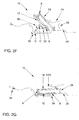
- FIG. 2F A corresponding pivoting process is shown in FIG. 2F.
- the seat part 14 is shared with the backrest part 12 against the direction of rotation 30 about the second pivot axis B and the third pivot axis C and in the direction of rotation 30 about the fourth pivot axis D panned.
- the motor vehicle seat 10 is thus in from the vertical position VP a partially vertical intermediate position before reaching a second horizontal position HP2 swiveled.
- FIG. 2G finally shows the second horizontal position HP2 of the motor vehicle rear seat 10, in which an essentially flat loading floor is formed.
- FIG. 3 finally shows a possible pivot curve backrest part 48 and one Pivot curve seat part 50.
- the pivot curves 48, 50 relate to the positions of the Top edge backrest part 44 and front edge seat part 46, which at one Collision consideration play a special role.
- the Front edge seat part 46 and the top edge backrest part 44 play a special role because here the collision with the front seat 24 can be examined on the basis of positions 44/46.
- FIG. 3 shows a possible swivel curve backrest part 48 and one Pivot curve seat part 50 based on positions 44 and 46 of Figures 2A to 2G.
- positions 44 / 2A to 44 / 2G are for the Top edge backrest part 44 and 46 / 2A to 46 / 2G for the front edge seat part 46 shown.
- Positions 46 / 2A and 46 / 2B of Figures 2A and 2B are in Figure 3 congruent, so only one position is visible.
Landscapes
- Engineering & Computer Science (AREA)
- Aviation & Aerospace Engineering (AREA)
- Transportation (AREA)
- Mechanical Engineering (AREA)
- Seats For Vehicles (AREA)
- Chair Legs, Seat Parts, And Backrests (AREA)
- Vehicle Step Arrangements And Article Storage (AREA)
- Passenger Equipment (AREA)
Abstract
Description
- Figur 1
- einen Kraftfahrzeugsitz, insbesondere einen Kraftfahrzeugrücksitz, in einer Schnittdarstellung in seiner Gebrauchsstellung;
- Figur 2A
- den Kraftfahrzeugrücksitz in einer Schnittdarstellung in einer ersten Entriegelungsstellung;
- Figur 2B
- den Kraftfahrzeugrücksitz in einer Schnittdarstellung in einer in eine erste horizontale Position um eine erste Schwenkachse A geklappten Stellung;
- Figur 2C
- den Kraftfahrzeugrücksitz in einer Schnittdarstellung in einer um eine zweite Schwenkachse und eine dritte Schwenkachse teilweise vertikalen geklappten Position;
- Figur 2D
- den Kraftfahrzeugrücksitz in einer Schnittdarstellung in einer weiteren um die erste Schwenkachse B und die zweite Schwenkachse C teilweise vertikalen geschwenkten Position;
- Figur 2E
- den Kraftfahrzeugrücksitz in einer Schnittdarstellung in einer um die zweite Schwenkachse B und die dritte Schwenkachse C und eine vierte Schwenkachse D im Wesentlichen vertikal geklappten Position;
- Figur 2F
- den Kraftfahrzeugrücksitz in einer Schnittdarstellung in einer um die zweite Schwenkachse B, die dritte Schwenkachse C und die vierte Schwenkachse D unter einen vor dem Kraftfahrzeugrücksitz liegenden Fahrzeugsitz geklappten Position;
- Figur 2G
- den Kraftfahrzeugrücksitz in einer Schnittdarstellung in einer um die erste, zweite, dritte und vierte Schwenkachse A, B, C, D zusammengeklappten beziehungsweise umgelegten Position unter einem vor dem Fahrzeugrücksitz angeordneten Fahrzeugsitz und
- Figur 3
- eine beispielhafte Schwenkkurve-Sitzteil und Schwenkkurve-Rückenlehnenteil anhand der Positionen einer Oberkante-Rückenlehnenteil und Vorderkante-Sitzteil.
- 10
- Fahrzeugsitz/Fahrzeugrücksitz
- 12
- Rückenlehnenteil
- 14
- Sitzteil
- 16
- erstes Verriegelungselement
- 18
- zweites Verriegelungselement
- 20
- Führungselemente
- 20A
- erstes Führungselement
- 20B
- zweites Führungselement
- 22
- Verbindungselemente
- 22A
- erstes Verbindungselement
- 22B
- zweites Verbindungselement
- 22C
- drittes Verbindungselement
- 22D
- viertes Verbindungselement
- 24
- vorgelagerter Fahrzeugsitz
- 26
- Karosserie
- 28
- Rahmen des vorgelagerten Fahrzeugsitzes
- 30
- Rotationsrichtung
- 32
- Klapp- beziehungsweise Umlegerichtung
- 34
- Vertiefung
- 36
- erstes Halteelement
- 38
- zweites Halteelement
- 40
- Ausrückrichtung
- 42
- Ausnehmung
- 44
- Oberkante-Rückenlehnenteil
- 46
- Vorderkante-Sitzteil
- 48
- Schwenkkurve-Rückenlehnenteil
- 50
- Schwenkkurve-Sitzteil
- A
- erste Schwenkachse
- B
- zweite Schwenkachse
- C
- dritte Schwenkachse
- D
- vierte Schwenkachse
- HP1
- erste horizontale Position
- HP2
- zweite horizontale Position
- VP
- vertikale Position
- r1
- erster Schwenkradius (B → C)
- r2
- zweiter Schwenkradius (C → D)
- r3
- dritter Schwenkradius (B → D)
Claims (26)
- Fahrzeugsitz (10), insbesondere klappbarer Fahrzeugrücksitz für ein Kraftfahrzeug, der mindestens ein Rückenlehnenteil (12) und mindestens ein Sitzteil (14) umfasst und mit einer Karosserie (26) verbindbar ist, wobei das mindestens eine Rückenlehnenteil (12) um eine erste Schwenkachse (A) schwenkbar und in Richtung des mindestens einen Sitzteiles (14) klappbar ist und das mindestens eine Sitzteil (14) gemeinsam mit dem mindestens einen Rückenlehnenteil (12) um mindestens eine zweite Schwenkachse (B) drehbeweglich angeordnet sind, dadurch gekennzeichnet, dass das mindestens eine Rückenlehnenteil (12) auf das mindestens eine Sitzteil (14) um die erste Schwenkachse (A) unter Ausbildung eines gestuften Ladebodens klappbar ist und das mindestens eine Rückenlehnenteil (14) und das mindestens eine Sitzteil (14) gemeinsam um die mindestens eine zweite Schwenkachse (B) unter einen vorgelagerten Sitz (24) und/oder in eine Vertiefung (34) unter Ausbildung eines im Wesentlichen ebenen Ladebodens schwenkbar sind.
- Fahrzeugsitz nach Anspruch 1, dadurch gekennzeichnet, dass das Sitzteil (12) und das Rückenlehnenteil (14) durch ein an der mindestens einen Schwenkachse (B) angreifendes erstes Führungselement (20A) und ein auf mindestens einer dritten Schwenkachse (C) mit dem ersten Führungselement (20A) verbundenes zweites Führungselement (20B) über mindestens eine vierte Schwenkachse (D) drehbeweglich an der Karosserie (26) angeordnet sind.
- Fahrzeugsitz nach Anspruch 1, dadurch gekennzeichnet, dass das erste und zweite Führungselement (20A, 20B) jeweils einen geringen Abstand zwischen der zweiten Schwenkachse (B) und der dritten Schwenkachse (C) beziehungsweise zwischen der dritten Schwenkachse (C) und der vierten Schwenkachse (D) ausbilden, so dass ein möglichst geringer erster und zweiter Schwenkradius (r1, r2) zwischen der zweiten Schwenkachse (B) und der dritten Schwenkachse (C) und der vierten Schwenkachse (D) unter Ausbildung eines möglichst geringen dritten Schwenkradius (r3) zwischen der zweiten Schwenkachse (B) und der vierten Schwenkachse (D) beim Schwenken von Sitzteil (14) und Rückenlehnenteil (12) ausbildbar ist.
- Fahrzeugsitz nach Anspruch 1 bis 2, dadurch gekennzeichnet, dass das Rückenlehnenteil (12) und das Sitzteil (14) über eine der Schwenkachsen (A, B, C, D) gleichzeitig oder nacheinander schwenkbar angeordnet sind und durch Überlagerung der Schwenkbewegungen eine Schwenkkurve-Rückenlehnenteil (48) und eine Schwenkkurve-Sitzteil (50) ausbildbar sind.
- Fahrzeugsitz nach Anspruch 3, dadurch gekennzeichnet, dass eine Oberkante-Rückenlehnenteil (44) und eine Vorderkante-Sitzteil (46) der Schwenkkurve (48) und der Schwenkkurve (50) zuordbar sind.
- Fahrzeugsitz (10) nach Anspruch 1 bis 4, dadurch gekennzeichnet, dass die Karosserie (26) eine in einer Klapp- beziehungsweise Umlegerichtung (32) entgegengesetzten Richtung angeordnete Ausnehmung (42) aufweist, in der die dritte Schwenkachse (C) unterhalb des mindestens einen Sitzteiles (14) karosserienah anordbar ist.
- Fahrzeugsitz nach einem der vorhergehenden Ansprüche, dadurch gekennzeichnet, dass das erste und/oder zweite Führungselement (20A, 20B) an eine Form der Karosserie (26) anpassbar sind.
- Fahrzeugsitz nach einem der vorhergehenden Ansprüche, dadurch gekennzeichnet, dass das erste und/oder zweite Führungselement (20A, 20B) sichelförmig oder s-förmig oder dergleichen ausbildbar sind.
- Fahrzeugsitz nach einem der vorhergehenden Ansprüche, dadurch gekennzeichnet, dass das mindestens eine Rückenlehnenteil (12) und das mindestens eine Sitzteil (14) über die zweite und/oder dritte und/oder vierte Schwenkachse (B, C, D) karosserienah zwischen der Karosserie (26) und einem vorgelagerten Sitz (24) entlangführbar angeordnet sind.
- Fahrzeugsitz nach einem der vorhergehenden Ansprüche, dadurch gekennzeichnet, dass das mindestens eine Sitzteil (14) und/oder das mindestens eine Rückenlehnenteil (12) über ein erstes und/oder ein zweites Verriegelungselement (16, 18) und ein zugehöriges erstes und/oder zweites Halteelement (36, 38) mit der Karosserie (26) verbindbar sind.
- Fahrzeugsitz nach einem der vorhergehenden Ansprüche, dadurch gekennzeichnet, dass das erste Verriegelungselement (16) ein Haken ist, der an dem mindestens einen Rückenlehnenteil (12) befestigt ist und das an der Karosserie befestigte erste Halteelement (36), insbesondere ein Rohr, umgreift.
- Fahrzeugsitz nach einem der vorhergehenden Ansprüche, dadurch gekennzeichnet, dass das zweite Verriegelungselement (18) ein Schloss ist, welches an dem mindestens einen Rückenlehnteil (12) und/oder an dem mindestens einen Sitzteil (14) befestigt ist und in ein zweites Halteelement (38), insbesondere in eine Stiftplatte, eingreift.
- Fahrzeugsitz nach einem der vorhergehenden Ansprüche, dadurch gekennzeichnet, dass das mindestens eine Rückenlehnenteil (12) über ein erstes bewegliches Verbindungselement (22A) mit dem mindestens einen Sitzteil (14) an der ersten Schwenkachse (A) verbunden ist.
- Fahrzeugsitz nach einem der vorhergehenden Ansprüche, dadurch gekennzeichnet, dass das mindestens eine Sitzteil (14) über ein zweites bewegliches Verbindungselement (22B) mit dem ersten Führungselement (20A) an der zweiten Schwenkachse (B) verbunden ist.
- Fahrzeugsitz nach einem der vorhergehenden Ansprüche, dadurch gekennzeichnet, dass das erste Führungselement (20A) über ein drittes bewegliches Verbindungselement (22C) mit dem zweiten Führungselement (20B) an der dritten Schwenkachse (C) verbunden ist.
- Fahrzeugsitz nach einem der vorhergehenden Ansprüche, dadurch gekennzeichnet, dass das zweite Führungselement (20B) über ein viertes bewegliches Verbindungselement (22D) mit der Karosserie (26) an der vierten Schwenkachse (D) verbunden ist.
- Fahrzeugsitz nach einem der vorhergehenden Ansprüche, dadurch gekennzeichnet, dass die Verbindungselemente (22A, 22B, 22C und 22D) Scharniere oder dergleichen sind.
- Fahrzeugsitz nach einem der vorhergehenden Ansprüche, dadurch gekennzeichnet, dass das mindestens eine Sitzteil (14) gemeinsam mit dem mindestens einen Rückenlehnenteil (12) in eine Vertiefung (34) in der Karosserie (26) klappbar beziehungsweise umlegbar ist.
- Verfahren zum Zusammenklappen und Umlegen eines Fahrzeugsitzes, insbesondere eines klappbaren Fahrzeugrücksitzes für ein Kraftfahrzeug, zur Erzeugung eines Stauraumes, der mindestens ein Rückenlehnenteil (12) und mindestens ein Sitzteil (14) aufweist und mit einer Karosserie (26) verbunden ist, wobei das mindestens eine Rückenlehnenteil (12) um eine erste Schwenkachse (A) geschwenkt wird und in Richtung des mindestens einen Sitzteiles (14) geklappt wird und das mindestens eine Sitzteil (14) gemeinsam mit dem mindestens einen Rückenlehnenteil (12) mindestens um eine zweite Schwenkachse (B) bewegt wird, dadurch gekennzeichnet, dass unter Ausbildung einer ersten Schwenkkurve (48) für das mindestens eine Rückenlehnenteil (12) und einer Schwenkkurve (50) für das mindestens eine Sitzteil (14) das mindestens eine Rückenlehnenteil (12) auf das mindestens eine Sitzteil (14) um die erste Schwenkachse (A) unter Bildung eines gestuften Ladebodens geklappt wird und anschließend das mindestens eine Rückenlehnenteil (12) und das mindestens eine Sitzteil (14) gemeinsam mindestens über die zweite Schwenkachse (B) unter einen vorgelagerten Sitz (24) und/oder in eine Vertiefung (34) unter Bildung eines im Wesentlichen ebenen Ladebodens weiter verschwenkt werden.
- Verfahren nach Anspruch 19, dadurch gekennzeichnet, dass das mindestens eine Rückenlehnenteil (12) und das mindestens eine Sitzteil (14) unter einen vorgelagerten Sitz (24) und/oder in eine Vertiefung (34) unter Bildung eines im Wesentlichen ebenen Ladebodens über die zweite Schwenkachse (B) und/oder eine dritte Schwenkachse (C) und/oder eine vierte Schwenkachse (D) weiter verschwenkt werden.
- Verfahren nach Anspruch 18, dadurch gekennzeichnet, dass das Rückenlehnenteil (12) und das Sitzteil (14) auf einer Schwenkkurve (50) für das Sitzteil (14) und auf einer Schwenkkurve (48) für das Rückenlehnenteil (12) durch Ausführung geringer Schwenkradien (r1, r2, r3) zwischen den jeweiligen Schwenkachsen (B, C, D) eines ersten und zweiten Führungselementes (20A, 20B), an dem das Rückenlehnenteil (12) und das Sitzteil (12) schwenkbar angeordnet werden, in einem geringen Abstand zur Karosserie (26) geführt werden.
- Verfahren nach Anspruch 19, dadurch gekennzeichnet, dass eine Oberkante-Rückenlehnenteil (44) und eine Vorderkante-Sitzteil (46) der Schwenkkurve (48) und der Schwenkkurve (50) zugeordnet werden.
- Verfahren nach einem der vorhergehenden Ansprüche, dadurch gekennzeichnet, dass der Fahrzeugsitz (10) von der Karosserie (26) durch eine erste Ausrückbewegung in eine Ausrückrichtung (40) gelöst und das mindestens eine Sitzteil (14) um die erste Schwenkachse (A) in eine erste im Wesentlichen horizontale Position (HP1) rotiert und in eine parallele Lage zum mindestens einen Rückenlehnenteil (12) zusammengeklappt wird und einen gestuften Ladeboden ausbildet.
- Verfahren nach einem der vorhergehenden Ansprüche, dadurch gekennzeichnet, dass das mindestens eine Rückenlehnenteil (12) und das mindestens eine Sitzteil (14) um die zweite Schwenkachse (B) und/oder die dritte Schwenkachse (C) und/oder die vierte Schwenkachse (D) in eine im Wesentlichen vertikale Position (VP) rotieren.
- Verfahren nach einem der vorhergehenden Ansprüche, dadurch gekennzeichnet, dass das mindestens eine Rückenlehnenteil (12) und das mindestens eine Sitzteil (14) um die zweite Schwenkachse (B) und/oder die dritte Schwenkachse (C) und/oder die vierte Schwenkachse (D) rotieren und auf die Karosserie (26) umgelegt werden, so dass eine Rückseite des mindestens einen Rückenlehnenteiles (12) eine zweite im Wesentlichen horizontale Position (HP2) einnimmt, wodurch insbesondere der Stauraum eines Kraftfahrzeuges vergrößert wird und einen im Wesentlichen ebenen Ladeboden ausbildet.
- Verfahren nach einem der vorhergehenden Ansprüche, dadurch gekennzeichnet, dass der Fahrzeugsitz (10) durch Entriegelung eines ersten Verriegelungselementes (16) und/oder durch Entriegelung eines zweiten Verriegelungselementes (18) von der Karosserie (26) gelöst und nach erfolgter Rückverlagerung wieder verriegelt wird.
Applications Claiming Priority (2)
| Application Number | Priority Date | Filing Date | Title |
|---|---|---|---|
| DE10247398 | 2002-10-08 | ||
| DE10247398A DE10247398A1 (de) | 2002-10-08 | 2002-10-08 | Zusammenlegbarer Rücksitz zur Erzeugung eines Stauraumes |
Publications (2)
| Publication Number | Publication Date |
|---|---|
| EP1419927A1 true EP1419927A1 (de) | 2004-05-19 |
| EP1419927B1 EP1419927B1 (de) | 2007-12-12 |
Family
ID=32038498
Family Applications (1)
| Application Number | Title | Priority Date | Filing Date |
|---|---|---|---|
| EP03090286A Expired - Lifetime EP1419927B1 (de) | 2002-10-08 | 2003-09-04 | Zusammenlegbarer Rücksitz zur Erzeugung eines Stauraumes |
Country Status (3)
| Country | Link |
|---|---|
| EP (1) | EP1419927B1 (de) |
| AT (1) | ATE380708T1 (de) |
| DE (2) | DE10247398A1 (de) |
Cited By (2)
| Publication number | Priority date | Publication date | Assignee | Title |
|---|---|---|---|---|
| DE102004002265A1 (de) * | 2004-01-09 | 2005-08-04 | Volkswagen Ag | Kraftfahrzeugsitz mit schwingenartiger Karosserieanbindung des Sitzteiles |
| EP2321143A4 (de) * | 2008-09-10 | 2017-12-27 | Johnson Controls Technology Company | Klappbarer sitz |
Citations (9)
| Publication number | Priority date | Publication date | Assignee | Title |
|---|---|---|---|---|
| DE2849985A1 (de) * | 1977-12-09 | 1979-06-21 | Citroen Sa | Fahrzeugsitz |
| DE29512327U1 (de) * | 1995-07-31 | 1995-09-28 | Steyr-Daimler-Puch Ag, Wien | Versenkbarer Kraftfahrzeugsitz |
| DE4422920A1 (de) * | 1994-06-30 | 1996-01-04 | Opel Adam Ag | Sitzanordnung, insbesondere für den Lade- bzw. Fahrgastraum eines Kraftfahrzeuges |
| US5839773A (en) * | 1997-10-15 | 1998-11-24 | Lear Corporation | Rolling stowable seat |
| JP2000185581A (ja) * | 1998-12-22 | 2000-07-04 | Kanto Auto Works Ltd | 自動車 |
| US6106046A (en) * | 1997-02-12 | 2000-08-22 | Daimler-Benz Ag | Vehicle seat arrangement |
| EP1077153A1 (de) * | 1999-08-10 | 2001-02-21 | Araco Kabushiki Kaisha | Hintersitz im Fahrgastraum |
| FR2814992A1 (fr) * | 2000-10-06 | 2002-04-12 | Faurecia Sieges Automobile | Siege de vehicule et vehicule equipe d'un tel siege |
| FR2817209A1 (fr) * | 2000-11-29 | 2002-05-31 | Peugeot Citroen Automobiles Sa | Agencement de siege dans un vehicule automobile |
Family Cites Families (3)
| Publication number | Priority date | Publication date | Assignee | Title |
|---|---|---|---|---|
| FR2780003B1 (fr) * | 1998-06-17 | 2000-07-21 | Peugeot | Siege arriere reglable en position longitudinale dans un habitacle de vehicule automobile |
| DE19949759C1 (de) * | 1999-10-15 | 2000-10-26 | Faure Bertrand Sitztech Gmbh | Kraftfahrzeug-Rücksitz |
| DE10056084B4 (de) * | 2000-11-07 | 2011-02-17 | Volkswagen Ag | Fahrzeugsitz |
-
2002
- 2002-10-08 DE DE10247398A patent/DE10247398A1/de not_active Withdrawn
-
2003
- 2003-09-04 AT AT03090286T patent/ATE380708T1/de not_active IP Right Cessation
- 2003-09-04 DE DE50308776T patent/DE50308776D1/de not_active Expired - Lifetime
- 2003-09-04 EP EP03090286A patent/EP1419927B1/de not_active Expired - Lifetime
Patent Citations (9)
| Publication number | Priority date | Publication date | Assignee | Title |
|---|---|---|---|---|
| DE2849985A1 (de) * | 1977-12-09 | 1979-06-21 | Citroen Sa | Fahrzeugsitz |
| DE4422920A1 (de) * | 1994-06-30 | 1996-01-04 | Opel Adam Ag | Sitzanordnung, insbesondere für den Lade- bzw. Fahrgastraum eines Kraftfahrzeuges |
| DE29512327U1 (de) * | 1995-07-31 | 1995-09-28 | Steyr-Daimler-Puch Ag, Wien | Versenkbarer Kraftfahrzeugsitz |
| US6106046A (en) * | 1997-02-12 | 2000-08-22 | Daimler-Benz Ag | Vehicle seat arrangement |
| US5839773A (en) * | 1997-10-15 | 1998-11-24 | Lear Corporation | Rolling stowable seat |
| JP2000185581A (ja) * | 1998-12-22 | 2000-07-04 | Kanto Auto Works Ltd | 自動車 |
| EP1077153A1 (de) * | 1999-08-10 | 2001-02-21 | Araco Kabushiki Kaisha | Hintersitz im Fahrgastraum |
| FR2814992A1 (fr) * | 2000-10-06 | 2002-04-12 | Faurecia Sieges Automobile | Siege de vehicule et vehicule equipe d'un tel siege |
| FR2817209A1 (fr) * | 2000-11-29 | 2002-05-31 | Peugeot Citroen Automobiles Sa | Agencement de siege dans un vehicule automobile |
Non-Patent Citations (1)
| Title |
|---|
| PATENT ABSTRACTS OF JAPAN vol. 2000, no. 10 17 November 2000 (2000-11-17) * |
Cited By (3)
| Publication number | Priority date | Publication date | Assignee | Title |
|---|---|---|---|---|
| DE102004002265A1 (de) * | 2004-01-09 | 2005-08-04 | Volkswagen Ag | Kraftfahrzeugsitz mit schwingenartiger Karosserieanbindung des Sitzteiles |
| DE102004002265B4 (de) | 2004-01-09 | 2021-09-02 | Volkswagen Ag | Kraftfahrzeugsitz mit schwingenartiger Karosserieanbindung des Sitzteiles |
| EP2321143A4 (de) * | 2008-09-10 | 2017-12-27 | Johnson Controls Technology Company | Klappbarer sitz |
Also Published As
| Publication number | Publication date |
|---|---|
| ATE380708T1 (de) | 2007-12-15 |
| DE10247398A1 (de) | 2004-04-22 |
| EP1419927B1 (de) | 2007-12-12 |
| DE50308776D1 (de) | 2008-01-24 |
Similar Documents
| Publication | Publication Date | Title |
|---|---|---|
| DE69810193T2 (de) | Zusammenklappbare Struktur eines Hard-Tops für ein Cabriofahrzeug | |
| DE69828959T2 (de) | Drehender fahrzeugsitz | |
| DE102005054059B3 (de) | Lastenträger für Kraftfahrzeuge | |
| EP2129543B1 (de) | Fahrzeugsitz | |
| DE69801325T2 (de) | Verbesserte gelenkvorrichtung eines an einer kraftfahrzeugkarosserie schwenkbar angeordneten flügels | |
| DE102013012284A1 (de) | Easy-Entry-Verstellmechanismus für Dive-Down-Fahrzeugsitze beziehungsweise Sitzanlagen | |
| DE4316485A1 (de) | Klappverdeck für Kraftfahrzeuge | |
| DE2640959C2 (de) | Kraftfahrzeugsitz, insbesondere Rücksitz für Kombi-Kraftfahrzeuge | |
| DE102021204312A1 (de) | Lenksäule mit klappbarer lenkradstruktur | |
| DE10109822A1 (de) | Verriegelungsmechanismus für eine Sitzbaugruppe | |
| DE10257601A1 (de) | Sitzvorrichtung mit einem Befestigungssystem | |
| DE102004007863A1 (de) | Fahrzeugsitz, insbesondere für ein Kraftfahrzeug, mit einer klappbaren Lehne und einer klappbaren Sitzbasis und Verfahren | |
| DE10242968B4 (de) | Fahrzeugsitz, insbesondere Kraftfahrzeugsitz | |
| EP1419927B1 (de) | Zusammenlegbarer Rücksitz zur Erzeugung eines Stauraumes | |
| DE10237398B4 (de) | Fahrzeugsitz | |
| DE10358720B4 (de) | Kraftfahrzeugsitz mit getrennter Klappung von Sitzteil und Rückenlehnenteil | |
| DE102006056715B4 (de) | Fahrzeugsitz, insbesondere Kraftfahrzeugsitz | |
| DE102005017772B4 (de) | Kraftfahrzeug mit einem schwenkbaren Sitz | |
| DE102006047383A1 (de) | Kraftfahrzeugsitz mit einem über Lenker verschwenkbaren Sitzteil | |
| DE9307481U1 (de) | Klappverdeck für Kraftfahrzeuge | |
| DE19929036B4 (de) | Verstellbarer Sitz, insbesondere für die zweite oder dritte Sitzreihe eines Kraftfahrzeuges | |
| DE102004056810B4 (de) | Sitz, der eine Verstellvorrichtung aufweist | |
| DE10344322B4 (de) | "Foldflat" Sitze | |
| DE102007020876B4 (de) | Klappbarer Sitz | |
| EP2077199A2 (de) | Windschotteinrichtung mit synchronisiertem Doppelgelenk |
Legal Events
| Date | Code | Title | Description |
|---|---|---|---|
| PUAI | Public reference made under article 153(3) epc to a published international application that has entered the european phase |
Free format text: ORIGINAL CODE: 0009012 |
|
| AK | Designated contracting states |
Kind code of ref document: A1 Designated state(s): AT BE BG CH CY CZ DE DK EE ES FI FR GB GR HU IE IT LI LU MC NL PT RO SE SI SK TR |
|
| AX | Request for extension of the european patent |
Extension state: AL LT LV MK |
|
| RIN1 | Information on inventor provided before grant (corrected) |
Inventor name: SULOWSKI, ROBERT Inventor name: RYNKIEWICZ, KRZYSZTOF Inventor name: LUZNY, ARTUR Inventor name: HEIRINGHOFF, HEINZ |
|
| RIN1 | Information on inventor provided before grant (corrected) |
Inventor name: HEIRINGHOFF, HEINZ Inventor name: LUZNY, ARTUR Inventor name: SULOWSKI, ROBERT Inventor name: RYNKIEWICZ, KRZYSZTOF |
|
| 17P | Request for examination filed |
Effective date: 20041119 |
|
| AKX | Designation fees paid |
Designated state(s): AT BE BG CH CY CZ DE DK EE ES FI FR GB GR HU IE IT LI LU MC NL PT RO SE SI SK TR |
|
| 17Q | First examination report despatched |
Effective date: 20060831 |
|
| GRAP | Despatch of communication of intention to grant a patent |
Free format text: ORIGINAL CODE: EPIDOSNIGR1 |
|
| RIN1 | Information on inventor provided before grant (corrected) |
Inventor name: SULOWSKI, ROBERT Inventor name: RYNKIEWICZ, KRZYSZTOF Inventor name: LUZNY, ARTUR Inventor name: HEIRINGHOFF, HEINZ |
|
| GRAS | Grant fee paid |
Free format text: ORIGINAL CODE: EPIDOSNIGR3 |
|
| GRAA | (expected) grant |
Free format text: ORIGINAL CODE: 0009210 |
|
| AK | Designated contracting states |
Kind code of ref document: B1 Designated state(s): AT BE BG CH CY CZ DE DK EE ES FI FR GB GR HU IE IT LI LU MC NL PT RO SE SI SK TR |
|
| REG | Reference to a national code |
Ref country code: GB Ref legal event code: FG4D Free format text: NOT ENGLISH |
|
| REG | Reference to a national code |
Ref country code: CH Ref legal event code: EP |
|
| REG | Reference to a national code |
Ref country code: IE Ref legal event code: FG4D Free format text: LANGUAGE OF EP DOCUMENT: GERMAN |
|
| REF | Corresponds to: |
Ref document number: 50308776 Country of ref document: DE Date of ref document: 20080124 Kind code of ref document: P |
|
| GBT | Gb: translation of ep patent filed (gb section 77(6)(a)/1977) |
Effective date: 20080227 |
|
| PG25 | Lapsed in a contracting state [announced via postgrant information from national office to epo] |
Ref country code: SE Free format text: LAPSE BECAUSE OF FAILURE TO SUBMIT A TRANSLATION OF THE DESCRIPTION OR TO PAY THE FEE WITHIN THE PRESCRIBED TIME-LIMIT Effective date: 20080312 |
|
| PG25 | Lapsed in a contracting state [announced via postgrant information from national office to epo] |
Ref country code: FI Free format text: LAPSE BECAUSE OF FAILURE TO SUBMIT A TRANSLATION OF THE DESCRIPTION OR TO PAY THE FEE WITHIN THE PRESCRIBED TIME-LIMIT Effective date: 20071212 Ref country code: NL Free format text: LAPSE BECAUSE OF FAILURE TO SUBMIT A TRANSLATION OF THE DESCRIPTION OR TO PAY THE FEE WITHIN THE PRESCRIBED TIME-LIMIT Effective date: 20071212 Ref country code: SI Free format text: LAPSE BECAUSE OF FAILURE TO SUBMIT A TRANSLATION OF THE DESCRIPTION OR TO PAY THE FEE WITHIN THE PRESCRIBED TIME-LIMIT Effective date: 20071212 |
|
| NLV1 | Nl: lapsed or annulled due to failure to fulfill the requirements of art. 29p and 29m of the patents act | ||
| PG25 | Lapsed in a contracting state [announced via postgrant information from national office to epo] |
Ref country code: CZ Free format text: LAPSE BECAUSE OF FAILURE TO SUBMIT A TRANSLATION OF THE DESCRIPTION OR TO PAY THE FEE WITHIN THE PRESCRIBED TIME-LIMIT Effective date: 20071212 Ref country code: ES Free format text: LAPSE BECAUSE OF FAILURE TO SUBMIT A TRANSLATION OF THE DESCRIPTION OR TO PAY THE FEE WITHIN THE PRESCRIBED TIME-LIMIT Effective date: 20080323 |
|
| ET | Fr: translation filed | ||
| PG25 | Lapsed in a contracting state [announced via postgrant information from national office to epo] |
Ref country code: SK Free format text: LAPSE BECAUSE OF FAILURE TO SUBMIT A TRANSLATION OF THE DESCRIPTION OR TO PAY THE FEE WITHIN THE PRESCRIBED TIME-LIMIT Effective date: 20071212 Ref country code: RO Free format text: LAPSE BECAUSE OF FAILURE TO SUBMIT A TRANSLATION OF THE DESCRIPTION OR TO PAY THE FEE WITHIN THE PRESCRIBED TIME-LIMIT Effective date: 20071212 |
|
| PG25 | Lapsed in a contracting state [announced via postgrant information from national office to epo] |
Ref country code: PT Free format text: LAPSE BECAUSE OF FAILURE TO SUBMIT A TRANSLATION OF THE DESCRIPTION OR TO PAY THE FEE WITHIN THE PRESCRIBED TIME-LIMIT Effective date: 20080512 |
|
| REG | Reference to a national code |
Ref country code: IE Ref legal event code: FD4D |
|
| PLBE | No opposition filed within time limit |
Free format text: ORIGINAL CODE: 0009261 |
|
| STAA | Information on the status of an ep patent application or granted ep patent |
Free format text: STATUS: NO OPPOSITION FILED WITHIN TIME LIMIT |
|
| PG25 | Lapsed in a contracting state [announced via postgrant information from national office to epo] |
Ref country code: IE Free format text: LAPSE BECAUSE OF FAILURE TO SUBMIT A TRANSLATION OF THE DESCRIPTION OR TO PAY THE FEE WITHIN THE PRESCRIBED TIME-LIMIT Effective date: 20071212 Ref country code: DK Free format text: LAPSE BECAUSE OF FAILURE TO SUBMIT A TRANSLATION OF THE DESCRIPTION OR TO PAY THE FEE WITHIN THE PRESCRIBED TIME-LIMIT Effective date: 20071212 |
|
| 26N | No opposition filed |
Effective date: 20080915 |
|
| PG25 | Lapsed in a contracting state [announced via postgrant information from national office to epo] |
Ref country code: GR Free format text: LAPSE BECAUSE OF FAILURE TO SUBMIT A TRANSLATION OF THE DESCRIPTION OR TO PAY THE FEE WITHIN THE PRESCRIBED TIME-LIMIT Effective date: 20080313 |
|
| BERE | Be: lapsed |
Owner name: VOLKSWAGEN A.G. Effective date: 20080930 |
|
| PG25 | Lapsed in a contracting state [announced via postgrant information from national office to epo] |
Ref country code: MC Free format text: LAPSE BECAUSE OF NON-PAYMENT OF DUE FEES Effective date: 20080930 Ref country code: EE Free format text: LAPSE BECAUSE OF FAILURE TO SUBMIT A TRANSLATION OF THE DESCRIPTION OR TO PAY THE FEE WITHIN THE PRESCRIBED TIME-LIMIT Effective date: 20071212 Ref country code: BG Free format text: LAPSE BECAUSE OF FAILURE TO SUBMIT A TRANSLATION OF THE DESCRIPTION OR TO PAY THE FEE WITHIN THE PRESCRIBED TIME-LIMIT Effective date: 20080312 |
|
| REG | Reference to a national code |
Ref country code: CH Ref legal event code: PL |
|
| PG25 | Lapsed in a contracting state [announced via postgrant information from national office to epo] |
Ref country code: BE Free format text: LAPSE BECAUSE OF NON-PAYMENT OF DUE FEES Effective date: 20080930 Ref country code: CY Free format text: LAPSE BECAUSE OF FAILURE TO SUBMIT A TRANSLATION OF THE DESCRIPTION OR TO PAY THE FEE WITHIN THE PRESCRIBED TIME-LIMIT Effective date: 20071212 |
|
| PG25 | Lapsed in a contracting state [announced via postgrant information from national office to epo] |
Ref country code: LI Free format text: LAPSE BECAUSE OF NON-PAYMENT OF DUE FEES Effective date: 20080930 Ref country code: CH Free format text: LAPSE BECAUSE OF NON-PAYMENT OF DUE FEES Effective date: 20080930 Ref country code: AT Free format text: LAPSE BECAUSE OF NON-PAYMENT OF DUE FEES Effective date: 20080904 |
|
| PG25 | Lapsed in a contracting state [announced via postgrant information from national office to epo] |
Ref country code: HU Free format text: LAPSE BECAUSE OF FAILURE TO SUBMIT A TRANSLATION OF THE DESCRIPTION OR TO PAY THE FEE WITHIN THE PRESCRIBED TIME-LIMIT Effective date: 20080613 Ref country code: LU Free format text: LAPSE BECAUSE OF NON-PAYMENT OF DUE FEES Effective date: 20080904 |
|
| PG25 | Lapsed in a contracting state [announced via postgrant information from national office to epo] |
Ref country code: TR Free format text: LAPSE BECAUSE OF FAILURE TO SUBMIT A TRANSLATION OF THE DESCRIPTION OR TO PAY THE FEE WITHIN THE PRESCRIBED TIME-LIMIT Effective date: 20071212 |
|
| PGFP | Annual fee paid to national office [announced via postgrant information from national office to epo] |
Ref country code: IT Payment date: 20120920 Year of fee payment: 10 |
|
| PGFP | Annual fee paid to national office [announced via postgrant information from national office to epo] |
Ref country code: FR Payment date: 20121017 Year of fee payment: 10 |
|
| PGFP | Annual fee paid to national office [announced via postgrant information from national office to epo] |
Ref country code: GB Payment date: 20121001 Year of fee payment: 10 |
|
| REG | Reference to a national code |
Ref country code: DE Ref legal event code: R084 Ref document number: 50308776 Country of ref document: DE Effective date: 20130709 |
|
| GBPC | Gb: european patent ceased through non-payment of renewal fee |
Effective date: 20130904 |
|
| REG | Reference to a national code |
Ref country code: FR Ref legal event code: ST Effective date: 20140530 |
|
| PG25 | Lapsed in a contracting state [announced via postgrant information from national office to epo] |
Ref country code: GB Free format text: LAPSE BECAUSE OF NON-PAYMENT OF DUE FEES Effective date: 20130904 |
|
| PG25 | Lapsed in a contracting state [announced via postgrant information from national office to epo] |
Ref country code: FR Free format text: LAPSE BECAUSE OF NON-PAYMENT OF DUE FEES Effective date: 20130930 Ref country code: IT Free format text: LAPSE BECAUSE OF NON-PAYMENT OF DUE FEES Effective date: 20130904 |
|
| PGFP | Annual fee paid to national office [announced via postgrant information from national office to epo] |
Ref country code: DE Payment date: 20190930 Year of fee payment: 17 |
|
| REG | Reference to a national code |
Ref country code: DE Ref legal event code: R119 Ref document number: 50308776 Country of ref document: DE |
|
| PG25 | Lapsed in a contracting state [announced via postgrant information from national office to epo] |
Ref country code: DE Free format text: LAPSE BECAUSE OF NON-PAYMENT OF DUE FEES Effective date: 20210401 |