EP1418385B1 - Door locking for baking oven - Google Patents
Door locking for baking oven Download PDFInfo
- Publication number
- EP1418385B1 EP1418385B1 EP20030024822 EP03024822A EP1418385B1 EP 1418385 B1 EP1418385 B1 EP 1418385B1 EP 20030024822 EP20030024822 EP 20030024822 EP 03024822 A EP03024822 A EP 03024822A EP 1418385 B1 EP1418385 B1 EP 1418385B1
- Authority
- EP
- European Patent Office
- Prior art keywords
- locking device
- door
- door locking
- lock
- slide
- Prior art date
- Legal status (The legal status is an assumption and is not a legal conclusion. Google has not performed a legal analysis and makes no representation as to the accuracy of the status listed.)
- Expired - Fee Related
Links
Images


Classifications
-
- F—MECHANICAL ENGINEERING; LIGHTING; HEATING; WEAPONS; BLASTING
- F24—HEATING; RANGES; VENTILATING
- F24C—DOMESTIC STOVES OR RANGES ; DETAILS OF DOMESTIC STOVES OR RANGES, OF GENERAL APPLICATION
- F24C15/00—Details
- F24C15/02—Doors specially adapted for stoves or ranges
- F24C15/022—Latches
-
- H—ELECTRICITY
- H05—ELECTRIC TECHNIQUES NOT OTHERWISE PROVIDED FOR
- H05B—ELECTRIC HEATING; ELECTRIC LIGHT SOURCES NOT OTHERWISE PROVIDED FOR; CIRCUIT ARRANGEMENTS FOR ELECTRIC LIGHT SOURCES, IN GENERAL
- H05B6/00—Heating by electric, magnetic or electromagnetic fields
- H05B6/64—Heating using microwaves
- H05B6/6414—Aspects relating to the door of the microwave heating apparatus
- H05B6/6417—Door interlocks of the microwave heating apparatus and related circuits
Definitions
- the invention relates to a door lock for an oven and in particular for an oven with pyrolytic self-cleaning, which has a motor unit with an electric motor and a lock unit with a latch for interacting with a door part and other features according to the preamble of patent claim 1.
- a door lock according to the preamble of claim 1 is known from US 4,927,996 known. It comprises a lock unit with the elements required for locking, further comprising a safety micro-switch, which is directly switched on or off by the bolt according to its position. This will ensure that the locking state, ie the position of the serving for locking the door parts can be safely and reliably detected by this microswitch and taken into account in the switching signals for the electric motor.
- microswitch as well as the other cams are exposed to the high temperatures not only during the normal operating conditions of the oven, but in particular must withstand the extremely high temperatures during the pyrolysis operation.
- the invention is therefore based on the object to provide measures to ensure that even very high operating temperatures for each required electrical components are harmless.
- the lock unit thus includes only mechanical components, with the result that the electrical components are no longer at risk due to high temperature. This is especially true because the lock unit and the electrical components with the actuator for the safety micro-switch can be thermally separated from each other.
- the respective interest position of the cooperating with the door bolt in the lock unit is now no longer taken in contrast to the prior art at the latch side end of the power transmission element, but this happens in the range of the other, motor-side end. As a result, both a perfect function and high reliability for all and in particular the electrical components is ensured.
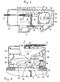
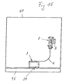
- a door lock 1 for the oven door 45 of a baking oven 47 comprises according to the Fig. 1 and 15 a motor unit 2, a lock unit 3 and a power transmission element 4, which connects the motor unit 2 with the lock unit 3.
- the power transmission element 4 is according to embodiment, a Bowden cable 4. From the oven 47 are in Fig. 1 only a cover plate 5 with a baffle 5 'and an oven flange 6 indicated on which the lock unit 3 is attached.
- the motor unit 2 is on the cover plate 5 behind the baffle 5 'angeordent so that they can be in the range of a controlled cooling air flow.
- the motor unit 2 has a motor 8 with motor switch 9, with switch 10 for a rod controller and with switch 11 (micro switch) for the interlock request.
- the lock unit 3 contains no temperature-sensitive components. It can therefore be placed in an area of the oven with high ambient temperature (200 ° to 250 ° CC). In contrast, the motor unit 2 is placed in an area where a lower ambient temperature (80 ° to 100 ° C) prevails.
- the microswitch 11 on the motor unit 2 indicates the locked state of the oven and serves to switch the motor 8.
- FIG. 2 is a drive slide 13 is mounted in a housing 12 and displaceable by means of the motor 8, which drives the drive slide 13 via a motor gear 14, a drive pulley 15 with the axis 16 and an eccentric roller 17.
- the roller 17 engages an inner surface 18 of the drive slide 13 and thus determines - in conjunction with acting on the drive slide 13 spring forces - its movement.
- a rotating with the drive pulley 15 cam 19 with two diametrically opposed cam grooves 20 cooperates with the motor switch 9 and causes the shutdown of the motor 8 respectively after a 180 ° rotation of the drive pulley 15.
- Two mounted in the housing 12 support rollers 21 are located on the periphery the drive pulley 15 and prevent loading of the axle 16 by forces applied via the drive slide 13.
- One end of the Bowden cable 4 passes through the housing wall and is suspended in a suspension 22 which is slidable in the slide 13 in a guide longitudinally displaceable between two stops 23 and 24.
- a mounted on the drive slide 13 suspension spring 25 biases the suspension 22 in the direction of the stop 24, whereby a tensile force is applied to the Bowden cable 4.
- the suspension 22 is provided with a guide contour 26 for the displacement of a switching plunger 27, which is guided transversely displaceable in the drive slide 13 and cooperates with the micro-switch 11 and its switching pin.
- the guide contour 26 has a longitudinal direction in the direction of slide movement extending central control section 28 of the switch plunger 27 in the micro switch 11th actuated switch-on moved, as well as two flanking the middle control section 28 end portions 29 and 30, each withdraw the systems in the attachment 22 at one of the two stops 23, 24, the switch plunger 27 in a switch-off.
- the parts 22 to 30 form an actuating device for the microswitch 11.
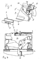
- the lock unit 3 has according to Fig. 3 a lock housing 31, which is provided with insert nuts for attachment to the oven flange 6.
- a lock slider 32 is guided longitudinally displaceable, the position of which is determined by the motor unit 2 via the Bowden cable 4.
- the lock slide 32 is biased by a valve housing 31 supported on the slide compression spring 33 - in Fig. 3 to the left - and has a contoured profile edge 34, at which a pivotable about a pivot axis 35 and biased by a rocker spring 36 in the counterclockwise direction biased rocker 37 rests with a rocker roller 38 mounted on it.
- a latch 39 in the form of a rotary latch with a hook-shaped latch end 40 is mounted pivotably about a latch axis 41 on the rocker 37 and biased by a torsion spring 42 in the counterclockwise direction in contact with a slide projection 43.
- the motor unit 2 and the lock unit 3 are located in the Fig. 2 or 3 in the starting position or in unlocked open position.
- the slides 13 and 32 of the two units 2 and 3 are in the right end position.
- the switching plunger 27 of the motor unit 2 assumes a raised position, so that the micro-switch 11 is turned off is.
- the movements of the various elements during the closing process are indicated by arrows.
- For the slide 13 and 32 and for the relative movement between the hanger 22 and the drive slide 13 as well as for the seal 44 between the oven door 45 and the oven flange 6 (FIGS. Fig. 3 ) are drawn O-lines to illustrate the occurring displacements. They are in the Fig. 8 and 10 in mm values.
- the rocker 37 designed as a rotary latch is in the retracted position within the lock housing 31.
- the rocker 37 wants to rotate under the action of the rocker arm 36 about the rocker axis 35 and move on the profile edge 34 pressing rocker roller 38 the lock slide 32 to the left.
- the torsion spring 42 wants to swing the latch 39 and move the hook-shaped latch end 40 against the door hook 7. But both takes place only when the Bowden cable 4 yields, so the engine 8 is started and thus both slides 13 and 32 of the units 2 and 3 can move to the left.
- the motor unit 2 has received the holding force for the open position of the lock unit 3 via the suspension 22 and the drive slide 13.
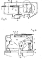
- the drive pulley 15 moves by 180 ° in the clockwise direction in the locked closed position ( FIGS. 9 and 10 ), wherein the two slides 13 and 32 shift to their left end position and the switch plunger 27, the micro-switch 11 turns on to signal the locking state.
- the drive slide 13 have moved by 28 mm and the lock slide 32 by 23 mm to the left, while the suspension 22 has moved relative to the drive slide 13 by 5 mm to the right.
- FIG. 4 has been after a displacement of the lock slide 32 by 10 mm of the slide projection 43 applied latch 39 is rotated by about 90 °, so that its hook-shaped latch end 40 rests on the door hook 7 and engages behind this.
- FIGS. 5 and 6 lead the continued slide movements to each 4.5 mm to the fact that the slide projection 43 lifts off the now held by the door hook 7 latch 39 and that the rocker 37 again undergoes a small counterclockwise rotation, so that the latch 39 and the door hook. 7 catch or lock together.
- the switch plunger 27 remains in its position without operating the micro-switch 11.
- Fig. 9 illustrates, and thus the lock state is signaled.
- the opening of the door 45 takes place in the reverse order, wherein first the microswitch 11 is switched and then the door is relieved, wherein the latch 39 moves out of the door hook 7 and finally turns back into the lock unit 3.
- Fig. 11 illustrates the case that there is a cable break in the Bowden cable 4. Then the suspension spring 25 relaxes further and moves the suspension 22 to the right until the stop 24, so that the switching plunger 27 enters the left end portion 29 of the guide contour 26 and the microswitch 11 is turned off so that it is now at a signal for correct locking is missing. This is meaningful for safety reasons, so that the cable break does not lead to an unlocking operation in the lock unit 3 when the door 45 is locked.
- Fig. 12 shows that the door 45 despite existing locking by 7 mm can be raised against the force of the rocker spring 36. This gap opening allows any necessary emergency release using a tool. It is important that in this mounting the door 45 which acts on the lock slider 32 slide pressure spring 33 prevents that it comes to a slide shift and consequent impermissible switching operations in the motor unit 2.
- FIGS. 13 and 14 illustrate the conditions that result in a locking operation with the door 45 not closed. Does the latch 39 when swinging not on the door hooks 7, then pivots the latch 39 through the guide surface 46 back into the lock housing 31 back. This prevents the protruding bolt end 40 and thus the lock unit 3 are damaged by a subsequent slamming of the door 45. Without door 45 acts on the lock slide 32 continue the force of the rocker 37 with the oscillating spring 36, so that it does not come in the motor unit 2 to a relative movement between the drive slide 13 and the suspension 22. Accordingly, the microswitch 11 continues to signal the open position so that it lacks a prerequisite for starting the pyrolysis operation.
- the microswitch 11 is actuated or switched on only when there is no fault with regard to the locking. Also, a subsequent error occurring after locking is signaled without it for unlocking comes, which is triggered only by an intended measure. Therefore, the lock state is surely detected via the microswitch. In addition, it serves the security that when locking the door is actively pulled and that protrude with unlocked door no lock components
- the invention has been described as applied to the pyrolysis of a baking oven.
- the lock with advantage can also be used independently of a Pyrolysegraphy to ensure a secure lock and to ensure security against unwanted door opening, such as in the sense of parental control.
- the scope is not limited to ovens, but also come for other stoves into consideration, in which a potential danger is given due to a strong heating.
- the latch 39 first emerges from the lock housing 31 through the guide contour on the lock slide 32 in the lock unit 3, then hooks and finally pulls the oven door 45 actively against the door seal 44.
- the motor used 8 requires no direction of rotation lock, since it can start in both directions.
- the one door hook 7 having latch 39 is two-armed and hinged to the rocker 37, that he 'acts on the slide 32 with its free arm 39.
- the latch 39 has a control cam 39 ", which at least temporarily cooperates with the profile 34 provided as a control cam 34 on the lock slide 32.
- the door lock 1 is designed with respect to the spring forces of the arranged in the motor unit 2 and the lock unit 3 springs such that the oven door is automatically and mechanically locked in a rope break. In addition, the pyrolysis does not start or is stopped immediately.
Description
Die Erfindung betrifft eine Türverriegelung für einen Backofen und insbesondere für einen Backofen mit pyrolytischer Selbstreinigung, die eine Motoreinheit mit einem Elektromotor sowie eine Schloßeinheit mit einem Riegel zum Zusammenwirken mit einem Türteil und weitere Merkmale gemäß dem Oberbegriff von Patentanspruch 1 aufweist.The invention relates to a door lock for an oven and in particular for an oven with pyrolytic self-cleaning, which has a motor unit with an electric motor and a lock unit with a latch for interacting with a door part and other features according to the preamble of
Eine Türverriegelung gemäß Oberbegriff von Anspruch 1 ist aus der
Nicht unproblematisch ist, daß der besagte Mikroschalter ebenso wie die übrigen Schloßteile den hohen Temperaturen nicht nur während der üblichen Betriebszustände des Backofens ausgesetzt sind, sondern insbesondere auch den extrem hohen Temperaturen während des Pyrolysebetriebes standhalten müssen. Der Erfindung liegt daher die Aufgabe zugrunde, Maßnahmen vorzusehen, mit deren Hilfe sichergestellt wird, daß auch sehr hohe Betriebstemperaturen für die jeweils benötigten elektrische Bauteile unschädlich sind.Not without problems is that said microswitch as well as the other cams are exposed to the high temperatures not only during the normal operating conditions of the oven, but in particular must withstand the extremely high temperatures during the pyrolysis operation. The invention is therefore based on the object to provide measures to ensure that even very high operating temperatures for each required electrical components are harmless.
Die Aufgabe wird mit den Merkmalen des kennzeichnenden Teiles von Patentanspruch 1 gelöst. Alle elektrischen Bauteile, einschließlich Sicherheits-Mikroschalter, und Elektromotor sind zusammen mit den erforderlichen, eine Betätigungseinrichtung für den Sicherheits-Mikroschalter bildenden Teilen in der Motoreinheit zusammengefaßt und zwischen der Schloßeinheit und der Motoreinheit ist ein Kraftübertragungselement vorgesehen, das nicht nur zur Übertragung von Kräften von der Motoreinheit auf die Schloßeinheit dient, sondern auch zur Übertragung von Steuerbefehlen von der Schloßeinheit in Richtung Motoreinheit mit dem/den dort befindlichen, zum Abfragen des Verriegelungszustandes dienenden Bauteil/Bauteilen.The object is achieved with the features of the characterizing part of
Die Schloßeinheit umfaßt somit ausschließlich mechanische Bauteile mit der Folge, daß die elektrischen Bauteile durch hohe Temperatur nicht mehr gefährdet sind. Dies gilt vor allem auch deshalb, weil die Schloßeinheit und die elektrischen Bauteile mit der Betätigungseinrichtung für den Sicherheits-Mikroschalter thermisch getrennt voneinander angeordnet werden können. Die jeweils interessierende Stellung des mit der Tür zusammenwirkenden Riegels in der Schloßeinheit wird jetzt im Gegensatz zum Stand der Technik nicht mehr an dem riegelseitigen Ende des Kraftübertragungselementes abgenommen, sondern dies geschieht im Bereich von dessen anderem, motorseitigen Ende. Dadurch ist sowohl eine einwandfreie Funktion als auch eine hohe Betriebssicherheit für alle und insbesondere die elektrischen Bauteile sichergestellt.The lock unit thus includes only mechanical components, with the result that the electrical components are no longer at risk due to high temperature. This is especially true because the lock unit and the electrical components with the actuator for the safety micro-switch can be thermally separated from each other. The respective interest position of the cooperating with the door bolt in the lock unit is now no longer taken in contrast to the prior art at the latch side end of the power transmission element, but this happens in the range of the other, motor-side end. As a result, both a perfect function and high reliability for all and in particular the electrical components is ensured.
Weitere Merkmale der Erfindung gehen aus der Beschreibung und den Ansprüchen im Zusammenhang mit der Zeichnung hervor. Die Erfindung wird nachstehend anhand eines Ausführungsbeispieles, das in der Zeichnung dargestellt ist, näher beschrieben. Dabei zeigen:
- Fig. 1.:
- eine perspektivische Ansicht der Türverriegelung mit der an Backofenteilen angeordneten Motoreinheit und der Schloßeinheit;
- Fig. 2.:
- einen der Offenstellung (Ausgangsstellung) entsprechenden Längsschnitt durch die Motoreinheit;
- Fig. 3.:
- einen gleichfalls in Offenstellung (Ausgangsstellung) befindlichen Längsschnitt durch die Schloßeinheit;
- Fig. 4.:
- die Schloßeinheit bei ausgeschwenktem Riegel;
- Fig. 5 + Fig. 6:
- die Motoreinheit und die Schloßeinheit mit vom teilweise angezogenen Riegel erfaßten Haken;
- Fig. 7 + Fig. 8:
- die Motoreinheit und die Schloßeinheit bei angezogenem Türhaken;
- Fig. 9 + Fig. 10:
- die Motoreinheit und die Schloßeinheit in der Verriegelungsstellung;
- Fig. 11 + Fig. 12:
- die Motoreinheit bei gerissenem Kraftübertragungselement;
- Fig. 13 :
- die Motoreinheit beim Ziehen an der verriegelten Tür;
- Fig. 14:
- die Schloßeinheit beim Verriegelungsvorgang mit nicht geschlossener Tür;
- Fig. 15.:
- in kleinerem Maßstab sowie schematisch eine Draufsicht auf die Kontur von Backofen und Ofentür sowie auf die Anordnung der die Türverriegelung bildenden Komponenten.
- Fig. 1 .:
- a perspective view of the door lock with the oven unit arranged on motor unit and the lock unit;
- Fig. 2 .:
- one of the open position (initial position) corresponding longitudinal section through the motor unit;
- Fig. 3 .:
- a likewise in the open position (initial position) located longitudinal section through the lock unit;
- Fig. 4 .:
- the lock unit with swung latch;
- Fig. 5 + Fig. 6:
- the motor unit and the lock unit with hooks engaged by the partially tightened latch;
- Fig. 7 + Fig. 8:
- the motor unit and the lock unit with the door hook tightened;
- Fig. 9 + Fig. 10:
- the motor unit and the lock unit in the locking position;
- Fig. 11 + Fig. 12:
- the motor unit with cracked power transmission element;
- Fig. 13:
- the motor unit when pulling on the locked door;
- Fig. 14:
- the lock unit during the locking process with the door not closed;
- Fig. 15 .:
- on a smaller scale and schematically a plan view of the contour of the oven and oven door and on the arrangement of the door lock forming components.
Eine Türverriegelung 1 für die Ofentür 45 eines Backofens 47 umfaßt gemäß den
Von der Backofentür 45 ist in
Die Motoreinheit 2 weist einen Motor 8 mit Motorschalter 9, mit Schalter 10 für einen Stabregler sowie mit Schalter 11 (Mikroschalter) für die Verriegelungsabfrage auf.The
Anders als die Motoreinheit 2 mit ihren temperaturempfindlichen Bauteilen wie dem Motor 8 um den Schaltern 9, 10 bzw. 11 enthält die Schloßeinheit 3 keine temperaturempfindlichen Bauteile. Sie kann daher in einem Bereich des Backofens mit hoher Umgebungstemperatur angeordnet werden (200° bis 250°CC). Dagegen ist die Motoreinheit 2 in einem Bereich plaziert, in dem eine niedrigere Umgebungstemperatur (80° bis 100°C) vorherrscht. Der Mikroschalter 11 an der Motoreinheit 2 zeigt den Verriegelungszustand des Backofens an und dient zum Schalten des Motors 8.Unlike the
Gemäß
Ein Ende des Bowdenzugs 4 durchgreift die Gehäusewand und ist in eine Einhängung 22 eingehängt, die im Schieber 13 in einer Führung längsverschieblich zwischen zwei Anschlägen 23 und 24 verschiebbar ist. Eine sich am Antriebsschieber 13 abstützende Einhängungsfeder 25 spannt die Einhängung 22 in Richtung auf den Anschlag 24 vor, wodurch eine Zugkraft auf den Bowdenzug 4 aufgebracht wird.One end of the
Die Einhängung 22 ist mit einer Führungskontur 26 für die Verlagerung eines Schaltstößels 27 versehen, der querverschieblich im Antriebsschieber 13 geführt ist und mit dem Mikroschalter 11 bzw. dessen Schaltstift zusammenwirkt. Die Führungskontur 26 weist einen längsgerichtet in Schieberbewegungsrichtung verlaufenden mittleren Steuerabschnitt 28, der den Schaltstößel 27 in die den Mikroschalter 11 betätigende Einschaltposition bewegt, sowie zwei den mittleren Steuerabschnitt 28 flankierende Endabschnitte 29 und 30 auf, die jeweils bei Anlagen der Einhängung 22 an einem der beiden Anschläge 23, 24 den Schaltstößel 27 in eine Ausschaltposition zurückziehen. So bilden die Teile 22 bis 30 eine Betätigungseinrichtung für den Mikroschalter 11.The
Die Schloßeinheit 3 weist gemäß
Die Motoreinheit 2 und die Schloßeinheit 3 befinden sich in den
Bei in Offenstellung befindlicher Schloßeinheit 3 gemäß
Mit dem Start des Motors 8 bewegt sich die Antriebsscheibe 15 um 180° im Uhrzeigersinn in die verriegelte Schließstellung (
Zwischenstadien innerhalb dieses Schließvorgangs sind in den
Gemäß
Die weitere Bewegung der beiden Schieber 13 und 32 gemäß
Bei angezogener Ofentür 45 wirkt die Kraft der Schwingenfeder 36 nicht mehr auf den Schloßschieber 32. Dieser hat damit seine linke Einstellung erreicht, während der Antriebsschieber 13 sich infolge der restlichen Drehung der Antriebsscheibe 15 noch um weitere 5 mm bis in seine linke Endstellung verlagert wird, wie es die
Somit wird der Mikroschalter 11 jetzt betätigt, wie es
Das Öffnen der Tür 45 erfolgt in umgekehrter Reihenfolge, wobei zuerst der Mikroschalter 11 geschaltet und dann die Tür entlastet wird, wobei sich der Riegel 39 aus dem Türhaken 7 bewegt und sich schließlich in die Schloßeinheit 3 zurückdreht.The opening of the
Die vorstehende Beschreibung macht deutlich, daß der Mikroschalter 11 nur dann betätigt bzw. eingeschaltet wird, wenn kein Fehler hinsichtlich der Verriegelung vorliegt. Auch ein nachträglich nach erfolgter Verriegelung auftretender Fehler wird signalisiert, ohne daß es zur Entriegelung kommt, die nur durch eine beabsichtigte Maßnahme ausgelöst wird. Daher wird der Verriegelungszustand sicher über den Mikroschalter festgestellt. Ergänzend dient es der Sicherheit, daß beim Verriegeln die Tür aktiv zugezogen wird und daß bei unverriegelter Tür keine Schloßbauteile vorstehenThe above description makes it clear that the
Vorstehend wurde die Erfindung in Anwendung bei der Pyrolysereinigung eines Backofens beschrieben. Es ist jedoch ohne weiteres ersichtlich, daß die Verriegelung mit Vorteil auch unabhängig von einer Pyrolysereinigung eingesetzt werden kann, um eine sichere Verriegelung zu gewährleisten und Sicherheit gegen eine unerwünschte Türöffnung zu gewährleisten, so beispielsweise auch im Sinne einer Kindersicherung. Schließlich beschränkt sich der Anwendungsbereich auch nicht auf Backöfen, vielmehr kommen dafür auch andere Öfen in Betracht, bei denen ein Gefahrenpotential aufgrund einer starken Aufheizung gegeben ist.In the above, the invention has been described as applied to the pyrolysis of a baking oven. However, it is readily apparent that the lock with advantage can also be used independently of a Pyrolysereinigung to ensure a secure lock and to ensure security against unwanted door opening, such as in the sense of parental control. Finally, the scope is not limited to ovens, but also come for other stoves into consideration, in which a potential danger is given due to a strong heating.
Es liegt schließlich auf der Hand, daß die verschiedenen Funktionen der erfindungsgemäßen Türverriegelung nur dann erreichbar sind, wenn die Federkräfte der verschiedenen Federn genau aufeinander abgestimmt sind. Die Größe dieser Kräfte ergibt sich aufgrund von jeweils zur Verfügung stehenden Hebelarmen der verschwenkbar oder verschiebbar angeordneten Teile.It is finally obvious that the various functions of the door lock according to the invention can only be achieved if the spring forces of the various springs are precisely matched. The size of these forces results from each available lever arms of the pivotally or slidably disposed parts.
Dazu gehört auch, daß die Anzugskraft im Bereich der Schloßeinheit über einige Millimeter nahezu konstant ist, so daß ein Setzen der Türdichtung während der Lebensdauer des Backofens ausgeglichen werden kann.This also includes that the tightening force in the region of the lock unit over a few millimeters is almost constant, so that a setting of the door seal can be compensated during the life of the oven.
Eine Notentriegelung ist zum Beispiel im Falle eines Stromausfalles jederzeit möglich, da die Ofentür einige Millimeter gegen die Kraft der beweglichen von Federn beaufschlagten Teile geöffnet werden kann. Dazu läßt sich die Ofentür von Hand in die in
Wesentlich ist auch, daß der Riegel 39 durch die Führungskontur an dem Schloßschieber 32 in der Schloßeinheit 3 zunächst aus dem Schloßgehäuse 31 austaucht, dann einhakt und schließlich die Ofentür 45 aktiv gegen die Türdichtung 44 zieht.It is also essential that the
Der eingesetzte Motor 8 benötigt keine Drehrichtungssperre, da er in beiden Richtungen anlaufen kann.The motor used 8 requires no direction of rotation lock, since it can start in both directions.
Der einen Türhaken 7 aufweisende Riegel 39 ist zweiarmig und derart an der Schwinge 37 angelenkt, daß er mit seinem freien Arm 39' den Schieber 32 beaufschlagt. Außerdem weist der Riegel 39 eine Steuerkurve 39" auf, die mit der als Profilkante 34 vorgesehenen Steuerkurve 34 am Schloßschieber 32 zumindest zeitweise zusammenwirkt.The one
Die Türverriegelung 1 ist bezüglich der Federkräfte der in der Motoreinheit 2 und der Schloßeinheit 3 angeordneten Federn derart gestaltet, daß die Ofentür bei einem Seilriss automatisch sowie mechanisch verriegelbar ist. Außerdem beginnt der Pyrolysebetrieb nicht bzw. wird sofort gestoppt.The
Claims (23)
- A door locking device for an oven, in particular for a baking oven with pyrolytic self-cleaning, comprising a motor unit (2) with an electric motor (8) and a motor switch (9), as well as a lock unit (3) with a bolt (39) for cooperating with a door element (7), as well as a force-transmission element (4) connecting the motor unit (2) with the lock unit (3), a safety microswitch (11) being additionally provided, which is activated when the oven door (45) is locked and which is deactivated in case of incorrect locking states, characterized ina) that all electric components, including the motor switch (9) and the electric motor (8), are combined, together with the safety microswitch (11) and with parts of the motor unit (2) forming an operating device (22 - 30) for the safety microswitch (11), in the motor unit (2), andb) that the force-transmission element (4) is provided for transmitting forces and is hung up, for transmitting control commands to the safety microswitch (11), in a suspension device (22) which is connected with a guiding profile (26) for displacing an actuating tappet (27) acting upon the safety microswitch (11) or the latter's actuating pin.
- The door locking device according to claim 1, characterized in
that the force-transmission element (4) is provided for tractive forces for opening the lock unit (3) and that the force-transmission element (4) is provided for transmitting, based on switch positions, control commands from the lock unit (3) to the operating device (22 - 30) for the safety microswitch (11). - The door locking device according to claim 1, characterized in
that the force-transmission element (4) is a Bowden pull wire. - The door locking device according to claim 1, characterized in
that the lock unit (3) including the bolt (39) for the oven door (45), on the one hand, and
the motor unit (2) with all electric components and the operating device (22 - 30) for the safety microswitch (11), on the other hand, are arranged in such a manner that they are thermally separated from each other. - The door locking device according to claim 1, characterized in
that the position of the force-transmission element (4) can be measured by the operating device (22 - 30) as a measure for the position of the bolt (39). - The door locking device according to claim 3, characterized in
that the bolt (39) including a door hook (7) is two-armed and is coupled to a rocker (37), loading with its free arm (39') a lock slide (32) which can be fastened to the Bowden pull wire (4). - The door locking device according to claim 6, characterized in
that the bolt (39) includes a control cam (39") and that the lock slide (32) includes a control cam (34) cooperating, at least temporarily, with said control cam (39"). - The door locking device according to claim 6 or 7, characterized in
that the bolt (39) can be pressed, by means of a rocker spring (36), against a profile edge (34) of the lock slide (32), which is prestressed by means of a slide pressure spring (33) and is connected with the force-transmission element (4). - The door locking device according to claim 8, characterized in
that the rocker (37) abuts on the profile edge (34) of the lock slide (32) via a rocker roll (38) carried on the rocker (37). - The door locking device according to claim 8 or 9, characterized in
that the bolt (39), the rocker (37) and the lock slide (32) as well as the springs (42, 36, 33) associated thereto, together with the abutments, are integrated in a common lock housing (31). - The door locking device according to claim 10, characterized in
that the bolt (39), when the door (45) is open, is arranged inside the lock housing (31), out of which it can be moved during the closing motion. - The door locking device according to claim 10 or 11, characterized in
that a guiding surface (46) acting upon the bolt (39) is provided such that the bolt (39) carrying out the closing motion can be shifted into the lock housing (31) again if it does not run against the door hook (7) behind which it has to engage. - The door locking device according to at least one of the preceding claims,
characterized in
that the motor unit (2) includes a driving slide (13) which can be moved in a housing (12) by means of an electric motor (8), said driving slide (13) being connected with the force-transmission element (4), the electric motor (8) moving the driving slide (13) via a driving disk (15) with an eccentrically arranged roll (17). - The door locking device according to claim 13, characterized in
that the driving disk (15) is supported on its circumference by two supporting rolls (21) taking up, via the force-transmission element or the Bowden pull wire (4), respectively, and the driving slide (13), the forces acting upon the driving disk (15). - The door locking device according to claim 14, characterized in
that a cam disk (19), rotating together with the driving disk (15), is provided, which cooperates with the motor switch (9) to switch off the electric motor (8). - The door locking device according to claim 15, characterized in
that the motor switch (9) switches off the electric motor (8) after each 180° rotation of the cam disk (19). - The door locking device according to claim 13, characterized in
that in the driving slide (13), a suspension device (22) for the Bowden pull wire (4) is carried in such a way that it is displaceable between two stops (23, 24) in direction of motion of the slide and is prestressed by a suspension spring (25) supported by the driving slide (13), so that the Bowden pull wire (4) is loaded with a tractive force. - The door locking device according to claim 17, characterized in
that the suspension device (22) includes a guiding profile (26) for displacing an actuating tappet (27) acting upon the safety microswitch (11) to signalize the locked condition. - The door locking device according to claim 17, characterized in
that the guiding profile (26) includes one central control section (28) extending in direction of motion of the slide, which moves the actuating tappet (27) forwards into the switch-on position actuating the microswitch (11), as well as two end sections (29, 30) flanking the central control section (28), each of which pulling back the actuating tappet (27) into a switch-off position when the suspension device (22) hits one of the two stops (23, 24). - The door locking device according to claim 13, characterized in
that, at the end of each motor-driven locking stroke, when due to the cooperation of the retracted bolt (39) with the door element (7), the latter takes up the force of the rocker spring (36), the driving slide (13) in the motor unit (2) undergoes an idle displacement without a corresponding displacement of the lock slide (32) in the lock unit (3), so that the suspension device (22) is displaced, under the action of the suspension spring (25), relative to the driving slide (13), pushing the actuating tappet (27) forwards, so that the microswitch (11) is actuated. - The door locking device according to claim 8, characterized in
that the slide pressure spring (33) of the lock unit (3) is dimensioned such that pulling on the locked door (45) will not trigger any switching processes in the motor unit (2). - The door locking device according to claim 8, characterized in
that the rocker spring (36) of the lock unit is dimensioned such that by pulling on the locked door (45), the latter can be opened up to a gap through which an emergency unlocking can be effected by means of an auxiliary tool. - The door locking device according to claim 8, characterized in
that the motor unit (2) and the lock unit (3), concerning their spring forces, are designed such that in case of a tear of the rope, the oven door (45) can be locked automatically as well as mechanically.
Applications Claiming Priority (2)
| Application Number | Priority Date | Filing Date | Title |
|---|---|---|---|
| DE2002151726 DE10251726A1 (en) | 2002-11-05 | 2002-11-05 | Door lock for an oven, in particular an oven with pyrolytic self-cleaning |
| DE10251726 | 2002-11-05 |
Publications (3)
| Publication Number | Publication Date |
|---|---|
| EP1418385A2 EP1418385A2 (en) | 2004-05-12 |
| EP1418385A3 EP1418385A3 (en) | 2005-04-20 |
| EP1418385B1 true EP1418385B1 (en) | 2009-12-09 |
Family
ID=32103379
Family Applications (1)
| Application Number | Title | Priority Date | Filing Date |
|---|---|---|---|
| EP20030024822 Expired - Fee Related EP1418385B1 (en) | 2002-11-05 | 2003-10-31 | Door locking for baking oven |
Country Status (2)
| Country | Link |
|---|---|
| EP (1) | EP1418385B1 (en) |
| DE (2) | DE10251726A1 (en) |
Families Citing this family (1)
| Publication number | Priority date | Publication date | Assignee | Title |
|---|---|---|---|---|
| EP2175200A1 (en) * | 2008-10-10 | 2010-04-14 | Elettrotecnica Rold Srl | Door locking device specifically for a pyrolytic oven |
Family Cites Families (4)
| Publication number | Priority date | Publication date | Assignee | Title |
|---|---|---|---|---|
| US4927996A (en) * | 1988-05-23 | 1990-05-22 | Robertshaw Controls Company | Cooking apparatus, door latching construction therefor and methods of making the same |
| US5419305A (en) * | 1993-09-02 | 1995-05-30 | Hanley; Roger T. | Automatic bimetal safety latch for self-cleaning oven doors |
| US5477030A (en) * | 1994-04-18 | 1995-12-19 | Robertshaw Controls Company | Cooking apparatus, latching construction therefor and methods of making the same |
| DE19504574C2 (en) * | 1995-02-11 | 2002-05-02 | Miele & Cie | Oven with a door locking device for microwave operation |
-
2002
- 2002-11-05 DE DE2002151726 patent/DE10251726A1/en not_active Ceased
-
2003
- 2003-10-31 DE DE50312199T patent/DE50312199D1/en not_active Expired - Lifetime
- 2003-10-31 EP EP20030024822 patent/EP1418385B1/en not_active Expired - Fee Related
Also Published As
| Publication number | Publication date |
|---|---|
| DE10251726A1 (en) | 2004-05-19 |
| EP1418385A3 (en) | 2005-04-20 |
| EP1418385A2 (en) | 2004-05-12 |
| DE50312199D1 (en) | 2010-01-21 |
Similar Documents
| Publication | Publication Date | Title |
|---|---|---|
| EP2865828B1 (en) | Motor vehicle door lock | |
| DE4427213C5 (en) | Door lock for a motor vehicle | |
| EP1828686B1 (en) | Door lock for an oven | |
| EP2148035B1 (en) | Drive device for refrigerator doors | |
| EP2291571B1 (en) | Closing device comprising a detent spring | |
| WO2015043705A1 (en) | Motor vehicle door handle | |
| DE102013222955A1 (en) | Double hood lock arrangement | |
| EP3783266B1 (en) | Cooking appliance with a cooking chamber closable by means of a door | |
| DE102016217647A1 (en) | Door handle system for a vehicle door | |
| EP3612697B1 (en) | Lock for a motor vehicle | |
| WO2012163330A1 (en) | Actuating device | |
| DE102008005181A1 (en) | Locking aid for pulling up e.g. door, at vehicle body, has securing unit set inactive, when locking element is engaged by locking unit and motor-driven movement of locking element begins and continues up to end position of locking element | |
| EP1614840B1 (en) | Assisted final closing device for an open wing or door of a vehicle | |
| EP2248966B1 (en) | Door lock with locking element and switchable locking element drive | |
| WO2000079086A1 (en) | Locking device and door-drive device comprising the same, for a door operated by a motor assembly | |
| EP1658410B1 (en) | Motor vehicle door lock | |
| EP1418385B1 (en) | Door locking for baking oven | |
| WO2019179557A1 (en) | Locking device for a fuel tank door | |
| DE10140957A1 (en) | Motor vehicle door lock | |
| WO2024017942A1 (en) | Motor vehicle lock | |
| WO2021204637A1 (en) | Motor vehicle lock | |
| EP2813646A2 (en) | Door lock for locking an appliance door | |
| DE202004020822U1 (en) | A method for locking an oven door during a pyrolytic cleaning process has an electric motor driven latch with vertical latitude | |
| DE102014113139A1 (en) | Lock assembly with latch deactivation device | |
| DE10359077A1 (en) | Security lock for doors of motor caravans and similar has actuating arrangement whose electromechanical parts can be operated by inner, outer door handles, internal press button and lock arrangement |
Legal Events
| Date | Code | Title | Description |
|---|---|---|---|
| PUAI | Public reference made under article 153(3) epc to a published international application that has entered the european phase |
Free format text: ORIGINAL CODE: 0009012 |
|
| AK | Designated contracting states |
Kind code of ref document: A2 Designated state(s): AT BE BG CH CY CZ DE DK EE ES FI FR GB GR HU IE IT LI LU MC NL PT RO SE SI SK TR |
|
| AX | Request for extension of the european patent |
Extension state: AL LT LV MK |
|
| PUAL | Search report despatched |
Free format text: ORIGINAL CODE: 0009013 |
|
| AK | Designated contracting states |
Kind code of ref document: A3 Designated state(s): AT BE BG CH CY CZ DE DK EE ES FI FR GB GR HU IE IT LI LU MC NL PT RO SE SI SK TR |
|
| AX | Request for extension of the european patent |
Extension state: AL LT LV MK |
|
| 17P | Request for examination filed |
Effective date: 20051020 |
|
| AKX | Designation fees paid |
Designated state(s): DE FR IT |
|
| 17Q | First examination report despatched |
Effective date: 20060901 |
|
| GRAP | Despatch of communication of intention to grant a patent |
Free format text: ORIGINAL CODE: EPIDOSNIGR1 |
|
| GRAS | Grant fee paid |
Free format text: ORIGINAL CODE: EPIDOSNIGR3 |
|
| GRAA | (expected) grant |
Free format text: ORIGINAL CODE: 0009210 |
|
| AK | Designated contracting states |
Kind code of ref document: B1 Designated state(s): DE FR IT |
|
| REF | Corresponds to: |
Ref document number: 50312199 Country of ref document: DE Date of ref document: 20100121 Kind code of ref document: P |
|
| PLBE | No opposition filed within time limit |
Free format text: ORIGINAL CODE: 0009261 |
|
| STAA | Information on the status of an ep patent application or granted ep patent |
Free format text: STATUS: NO OPPOSITION FILED WITHIN TIME LIMIT |
|
| 26N | No opposition filed |
Effective date: 20100910 |
|
| PG25 | Lapsed in a contracting state [announced via postgrant information from national office to epo] |
Ref country code: IT Free format text: LAPSE BECAUSE OF NON-PAYMENT OF DUE FEES Effective date: 20101031 |
|
| REG | Reference to a national code |
Ref country code: FR Ref legal event code: PLFP Year of fee payment: 13 |
|
| REG | Reference to a national code |
Ref country code: FR Ref legal event code: PLFP Year of fee payment: 14 |
|
| REG | Reference to a national code |
Ref country code: FR Ref legal event code: PLFP Year of fee payment: 15 |
|
| PGFP | Annual fee paid to national office [announced via postgrant information from national office to epo] |
Ref country code: DE Payment date: 20171024 Year of fee payment: 15 Ref country code: FR Payment date: 20171023 Year of fee payment: 15 |
|
| REG | Reference to a national code |
Ref country code: DE Ref legal event code: R119 Ref document number: 50312199 Country of ref document: DE |
|
| PG25 | Lapsed in a contracting state [announced via postgrant information from national office to epo] |
Ref country code: DE Free format text: LAPSE BECAUSE OF NON-PAYMENT OF DUE FEES Effective date: 20190501 |
|
| PG25 | Lapsed in a contracting state [announced via postgrant information from national office to epo] |
Ref country code: FR Free format text: LAPSE BECAUSE OF NON-PAYMENT OF DUE FEES Effective date: 20181031 |