EP3783266B1 - Cooking appliance with a cooking chamber closable by means of a door - Google Patents
Cooking appliance with a cooking chamber closable by means of a door Download PDFInfo
- Publication number
- EP3783266B1 EP3783266B1 EP20190665.8A EP20190665A EP3783266B1 EP 3783266 B1 EP3783266 B1 EP 3783266B1 EP 20190665 A EP20190665 A EP 20190665A EP 3783266 B1 EP3783266 B1 EP 3783266B1
- Authority
- EP
- European Patent Office
- Prior art keywords
- door
- drive unit
- force introduction
- cooking appliance
- carriage
- Prior art date
- Legal status (The legal status is an assumption and is not a legal conclusion. Google has not performed a legal analysis and makes no representation as to the accuracy of the status listed.)
- Active
Links
- 238000010411 cooking Methods 0.000 title claims description 133
- 230000033001 locomotion Effects 0.000 claims description 94
- 230000008878 coupling Effects 0.000 claims description 68
- 238000010168 coupling process Methods 0.000 claims description 68
- 238000005859 coupling reaction Methods 0.000 claims description 68
- 238000001514 detection method Methods 0.000 claims description 4
- 230000008054 signal transmission Effects 0.000 claims 1
- 238000011161 development Methods 0.000 description 14
- 230000018109 developmental process Effects 0.000 description 14
- 238000000034 method Methods 0.000 description 13
- 238000007789 sealing Methods 0.000 description 13
- 238000001816 cooling Methods 0.000 description 11
- 230000007246 mechanism Effects 0.000 description 5
- 230000008569 process Effects 0.000 description 4
- 230000005540 biological transmission Effects 0.000 description 3
- 238000004140 cleaning Methods 0.000 description 3
- 230000008901 benefit Effects 0.000 description 2
- 230000002349 favourable effect Effects 0.000 description 2
- 238000010438 heat treatment Methods 0.000 description 2
- 238000000197 pyrolysis Methods 0.000 description 2
- 230000008859 change Effects 0.000 description 1
- 238000010276 construction Methods 0.000 description 1
- 230000000694 effects Effects 0.000 description 1
- 238000005516 engineering process Methods 0.000 description 1
- 238000009434 installation Methods 0.000 description 1
- 238000004519 manufacturing process Methods 0.000 description 1
Images


Classifications
-
- F—MECHANICAL ENGINEERING; LIGHTING; HEATING; WEAPONS; BLASTING
- F24—HEATING; RANGES; VENTILATING
- F24C—DOMESTIC STOVES OR RANGES ; DETAILS OF DOMESTIC STOVES OR RANGES, OF GENERAL APPLICATION
- F24C15/00—Details
- F24C15/02—Doors specially adapted for stoves or ranges
- F24C15/023—Mounting of doors, e.g. hinges, counterbalancing
-
- E—FIXED CONSTRUCTIONS
- E05—LOCKS; KEYS; WINDOW OR DOOR FITTINGS; SAFES
- E05F—DEVICES FOR MOVING WINGS INTO OPEN OR CLOSED POSITION; CHECKS FOR WINGS; WING FITTINGS NOT OTHERWISE PROVIDED FOR, CONCERNED WITH THE FUNCTIONING OF THE WING
- E05F15/00—Power-operated mechanisms for wings
- E05F15/60—Power-operated mechanisms for wings using electrical actuators
- E05F15/603—Power-operated mechanisms for wings using electrical actuators using rotary electromotors
- E05F15/611—Power-operated mechanisms for wings using electrical actuators using rotary electromotors for swinging wings
-
- E—FIXED CONSTRUCTIONS
- E05—LOCKS; KEYS; WINDOW OR DOOR FITTINGS; SAFES
- E05Y—INDEXING SCHEME RELATING TO HINGES OR OTHER SUSPENSION DEVICES FOR DOORS, WINDOWS OR WINGS AND DEVICES FOR MOVING WINGS INTO OPEN OR CLOSED POSITION, CHECKS FOR WINGS AND WING FITTINGS NOT OTHERWISE PROVIDED FOR, CONCERNED WITH THE FUNCTIONING OF THE WING
- E05Y2201/00—Constructional elements; Accessories therefore
- E05Y2201/20—Brakes; Disengaging means, e.g. clutches; Holders, e.g. locks; Stops; Accessories therefore
- E05Y2201/218—Holders
-
- E—FIXED CONSTRUCTIONS
- E05—LOCKS; KEYS; WINDOW OR DOOR FITTINGS; SAFES
- E05Y—INDEXING SCHEME RELATING TO HINGES OR OTHER SUSPENSION DEVICES FOR DOORS, WINDOWS OR WINGS AND DEVICES FOR MOVING WINGS INTO OPEN OR CLOSED POSITION, CHECKS FOR WINGS AND WING FITTINGS NOT OTHERWISE PROVIDED FOR, CONCERNED WITH THE FUNCTIONING OF THE WING
- E05Y2201/00—Constructional elements; Accessories therefore
- E05Y2201/40—Motors; Magnets; Springs; Weights; Accessories therefore
- E05Y2201/404—Motors; Magnets; Springs; Weights; Accessories therefore characterised by the function
- E05Y2201/418—Motors; Magnets; Springs; Weights; Accessories therefore characterised by the function for holding
-
- E—FIXED CONSTRUCTIONS
- E05—LOCKS; KEYS; WINDOW OR DOOR FITTINGS; SAFES
- E05Y—INDEXING SCHEME RELATING TO HINGES OR OTHER SUSPENSION DEVICES FOR DOORS, WINDOWS OR WINGS AND DEVICES FOR MOVING WINGS INTO OPEN OR CLOSED POSITION, CHECKS FOR WINGS AND WING FITTINGS NOT OTHERWISE PROVIDED FOR, CONCERNED WITH THE FUNCTIONING OF THE WING
- E05Y2900/00—Application of doors, windows, wings or fittings thereof
- E05Y2900/30—Application of doors, windows, wings or fittings thereof for domestic appliances
- E05Y2900/308—Application of doors, windows, wings or fittings thereof for domestic appliances for ovens
Definitions
- the invention relates to a cooking appliance comprising a housing, a cooking chamber arranged in the housing with a cooking chamber opening and a door assigned to the cooking chamber opening, the door being pivotable about a rotation axis arranged on the housing in a range of movement between a closed position and an open position of the door, and wherein the cooking chamber is closed in the closed position of the door and accessible in the open position of the door.
- the known cooking appliances include a housing, a cooking chamber arranged in the housing with a cooking chamber opening and a door assigned to the cooking chamber opening, the door being movable in a range of movement between a closed position and an open position of the door, and the cooking chamber being closed in the closed position of the door and is accessible when the door is open.
- the door is automatically moved by a motor. This activates a coupling device connected to the door via a gear.
- the gear is designed to produce an increased force in the movement portion of the door that includes closing to pull the door against a seal.
- the DE 10 2004 061 231 B3 discloses a door lock for a stove in which a pivoting lever acts as a locking element. When closing the door, the lever not only performs a pivoting movement, but also a linear movement backwards, pulling the door closed.
- the invention therefore faces the problem of providing a cooking appliance of the type mentioned in which the door operating mechanism and the door operation are improved.
- the advantage that can be achieved with the invention is, in particular, that in a cooking appliance comprising a housing, a cooking chamber arranged in the housing with a cooking chamber opening and a door assigned to the cooking chamber opening, as well as in a method for its operation, the door operating mechanism and the door actuation are improved.
- the door operating mechanism and the door actuation are improved.
- the cooking space opening of the cooking space can be tightly closed by means of the door, for example during a cooking process.
- a cleaning process taking place in the cooking space such as pyrolytic cleaning of the cooking space or the like.
- the Special features when transferring the door into its open position and into its closed position are advantageously taken into account.
- the above-mentioned high contact pressure when moving the door is only required when it is transferred to its closed position.
- the door it is possible for the door to be movable and moved not only in the second movement section by means of the second drive unit, but also in the first Movement section, namely when the door is transferred to its open position.
- this embodiment of the invention is to be understood purely as an example.
- the design of the door operating mechanism can be freely selected within wide, suitable limits.
- the design of the cooking appliance according to the invention provides that the door is arranged to be pivotable about an axis of rotation arranged on the housing.
- the first drive unit and the second drive unit are each connected to the door in a force-transmitting manner for the automatic movement of the door by means of a common coupling device.
- the first and second drive units are each connected to the door in a force-transmitting manner for the automatic movement of the door by means of a common coupling device and the first drive unit and the second drive unit are each connected to the door by means of this common coupling device move automatically, a particularly simple and therefore cost-effective design of the cooking appliance is possible.
- the first drive unit and the second drive unit are connected to the door on the rotation axis side in a force-transmitting manner by means of the coupling device. In this way, for example, a compact and therefore space-saving arrangement of the door operating mechanism is made possible.
- the cooking appliance according to the invention can therefore be implemented in a way that saves components.
- a very advantageous development of the cooking appliance according to the invention provides that the first drive unit has a force introduction device, the force introduction device being between an engagement position in which the force introduction device is in force-transmitting engagement with the coupling device, and a non-engagement position in which the force introduction device is not force-transmitting with the coupling device is engaged, can be transferred back and forth. This makes it possible to either connect the first drive unit to the coupling device in a force-transmitting manner by means of the force introduction device or to release this force transmission connection.
- the first drive unit can, for example, be connected to the coupling device in a force-transmitting manner by means of the force introduction device only in the case when the above-mentioned high contact pressure of the door is required for a tight closure of the cooking chamber opening of the cooking chamber. Otherwise, the first drive unit can be decoupled from the coupling device in the aforementioned manner, so that any other movement of the door, manually or automatically, is significantly facilitated.
- the first drive unit has a force introduction device, the force introduction device being between an engagement position in which the force introduction device is in force-transmitting engagement with the coupling device, and a non-engagement position in which the force introduction device is not in force-transmitting engagement with the coupling device and is transferred back and forth.
- the first drive unit additionally has a motor, an eccentric connected to the motor in a torque-transmitting manner and a carriage, the carriage being resiliently mounted on the housing by means of at least one return spring in such a way that the The force introduction device mounted on the carriage can be automatically transferred from its engaged position to its non-engaged position by means of the return spring, and the motor, the eccentric and the carriage are designed and arranged in relation to one another in such a way that the force introduction device mounted on the carriage can be moved by means of the motor, the eccentric and the carriage from their non-intervention position can be automatically transferred to their engagement position.
- the first drive unit can be implemented particularly easily in terms of construction and production technology.
- the carriage can be mounted on the housing directly or indirectly.
- the first drive unit and the second drive unit can be at least partially designed as an assembly, which is then connected as a whole to the housing in a force-transmitting manner. Accordingly, the carriage can be resiliently mounted on a mounting plate or the like of this assembly.
- the force introduction device is resiliently mounted on the carriage by means of at least one force introduction spring, with a range of movement of the force introduction device relative to the carriage being limited by means of mutually corresponding limiting means of the force introduction device and the carriage.
- This enables the force introduction device arranged on the carriage to rest resiliently on the coupling device in the engaged position of the force introduction device.
- the door can be manually moved from its closed position to its open position against a spring force of the force introduction spring, for example by a user of the cooking appliance.
- the coupling device has a coupling link, the force introduction device of the first drive unit in its engaged position being in engagement with the coupling device by means of the coupling link, preferably that the coupling link has a coupling link slope for redirecting a force introduction device into the Coupling device has force introduced.
- the structural design of the cooking appliance according to the invention is further simplified.
- the preferred embodiment of this development has the additional advantage that by means of the Force introduction device into the coupling device can be redirected in a simple and robust manner by means of the coupling link slope. Accordingly, the first drive unit can be arranged more flexibly and freely relative to the coupling device, so that the installation space available in the respective cooking appliance according to the invention can be used in a manner adapted to the requirements of the individual case.
- the coupling device has a control link, the control link being designed to actuate at least one switch connected to a control of the cooking appliance in a signal-transmitting manner, preferably that a plurality of switches can be actuated by means of the control link, wherein by means of of the individual switches, the open position of the door, the closed position of the door and an intermediate position of the door can be detected, and wherein the first movement section is formed between the intermediate layer and the closed position of the door and the second movement section is formed between the intermediate layer and the open position of the door.
- the preferred embodiment of this development is particularly advantageous since, among other things, the positions of the door that are important for controlling the first and second drive units for the automatic movement of the door can be detected.
- the aforementioned detection of the at least one position of the door can of course also be used for other functions of the cooking appliance, for example for cooking functions or a pyrolysis function of the cooking appliance, in the control of the cooking appliance.
- the force introduction device of the first drive unit can be transferred from its engaged position to its non-engaged position and/or from its non-engaged position to its engaged position depending on the detection of the intermediate layer.
- the control of the first drive unit is realized in a particularly obvious way by means of the control of the cooking appliance.
- the intermediate layer is designed as the position of the door in which the door is in contact with a sealing device surrounding the cooking space opening, i.e. is in contact with the aforementioned sealing device, without significantly compressing this sealing device.
- the force introduction device of the first drive unit can then be transferred from its non-engaged position into its engaged position, so that the door is firmly against by means of the first drive unit and the coupling device the aforementioned sealing device is pressed, namely in such a way that the cooking space opening is essentially tightly closed by means of the door and the sealing device.
- the first movement section is positioned on the closing position side and the second movement section is positioned on the opening position side.
- a high actuating force for example a contact pressure for the door to fit tightly against the above-mentioned sealing device, is required when operating the door, particularly when the door is moved into its closed position. Accordingly, it is advantageous to carry out a change in the actuation of the door from the second drive unit to the first drive unit for the corresponding movement section in the movement range of the door.
- a further advantageous development provides that the door is automatically transferred to at least one intermediate position of the door by means of the first drive unit and/or the second drive unit and is held in this intermediate position, the intermediate layer of the door being positioned between the closed position and the open position of the door .
- the door can not only be automatically moved back and forth between its closed position and its open position. Instead, the door can also occupy at least one intermediate position between its closed position and its open position.
- the at least one intermediate layer of the door can be freely selected within wide, suitable limits.
- a particularly advantageous development of the method according to the invention provides that an automatic program for rapid cooling of the cooking chamber is stored in a control of the cooking appliance, the door being automatically transferred to an intermediate position corresponding to this automatic program when the automatic program is executed. This enables a rapid cooling function in the cooking appliance according to the invention without additional design effort.
- the cooking appliance 2 is designed as a household oven and comprises a housing 4, a cooking chamber 6 arranged in the housing 4 with a cooking chamber opening 8 and a door 10 assigned to the cooking chamber opening 8, the door 10 being in a range of movement between one in the Fig. 3 shown closed position and one in the Fig. 1 shown opening position of the door 10 is movable.
- the cooking space 6 is closed in the closed position of the door 10 and accessible in the open position of the door 10, with a first drive unit 12 and a second drive unit 14 each being arranged on the housing 4 for the automatic movement of the door 10, the door 10 being moved by means of the first drive unit 12 in a first movement section of the movement range and by means the second drive unit 14 is movable in a second movement section of the movement range of the door 10.
- the door 10 is in the first movement section of the movement range by means of the first drive unit 12 in the first movement section of the movement range and by means of the second drive unit 14 in the second movement section of the movement range of the door, depending on the transfer of the door 10 into its open position or into its closed position 10 movable, which will be explained in more detail below.
- the door 10 is arranged to be pivotable about an axis of rotation 16 arranged on the housing 4, the first drive unit 12 being arranged on a side of the cooking chamber opening 8 opposite the axis of rotation 16 on the housing 4 and the second drive unit 14 being connected to the door 10 on the axis of rotation in a force-transmitting manner . See the Fig. 1 and 2 .
- the first movement section of the door 10 ranges from 0° to approximately 3° door opening, with 0° door opening being the one in the Fig. 3 shown closed position of the door 10 corresponds.
- the second movement section of the door 10 ranges from about 3° to about 85° door opening, with 85° door opening being the one in the Fig. 1 shown opening position of the door 10 corresponds.
- the first movement section is therefore positioned on the closing position side and the second movement section is positioned on the opening position side.
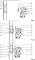
- the first drive unit 12 has a base plate 18 and a carriage 20, the first drive unit 12 being fastened to the housing 4 by means of the base plate 18 and the carriage 20 being movably held on the base plate 18. See the Fig. 1 to 12 in the synopsis.
- the carriage 20 has a base part 22 assigned to the base plate 18 and an actuating part 24 assigned to the door 10, the base part 22 and the actuating part 24 being resiliently connected to one another. See also this Fig. 1 to 12 in the synopsis.
- the carriage 20 as a whole, i.e. base part 22 and actuating part 24, is between one in the by means of an electric motor 25 Fig. 2 to 5 and 8 to 12 rest position shown and one in the 6, 7a and 7b shown gripping position can be moved back and forth.
- the door 10 and the first drive unit 12 have mutually corresponding coupling means 26, 28, wherein the door 10 and the first drive unit 12 can be coupled in a force-transmitting manner by means of these coupling means 26, 28.
- the coupling means 26 is designed as a hook and is arranged on the actuating part 24 of the carriage 22.
- the hook 26 can be moved back and forth between an actuation position and a non-actuation position, the door 10 being connectable to the hook 26 in a force-transmitting manner in the actuation position of the hook 26 and not being able to be connected to the hook 26 in a force-transmitting manner in the non-actuation position of the hook 26.
- the operating position of the hook 26 is in the Fig.
- the non-actuation position of the hook 26 is in the Figs. 4 and 5 shown.
- the hook 26 is initially moved from the door 10 when it is transferred from its open position to its closed position against the spring force of a spring element (not shown).
- Fig. 6 illustrated actuation position is transferred in the direction of its non-actuation position, in order to then be transferred again into its actuation position by means of the spring force of this spring element when the door 10 is further transferred from its open position to its closed position. This will be explained in more detail below.
- the coupling means 28 of the door 10 corresponding to the hook 26 is designed in the present exemplary embodiment as an undercut in an opening 30 of the door 10.
- the hook 26 can be automatically moved back and forth between its actuation position and its non-actuation position by means of an electric motor 32 of the first drive unit 12.
- the first drive unit 12 is simultaneously designed as a locking unit for holding the door 10 in its closed position.
- the hook 26 is simultaneously designed as a locking hook for holding the door 10 in its closed position. Accordingly, it is possible by means of the first drive unit 12 to hold the door 10 in its closed position.
- the closure unit, in particular the hook and an undercut (coupling means 28) are designed so that there is a frictional connection, but not a positive connection.
- the door 10 can therefore be torn open even with a hook 26 in the closed position. There is therefore no locking by the locking unit. Locking the door 10 in its closed position is necessary, for example, when the cooking appliance is in pyrolysis mode and can be implemented by a separate locking unit.
- the door 10 of the cooking appliance 2 is initially in the Fig. 3 closed position shown, so that the cooking space opening 8 and thus the cooking space 6 is closed. In the closed position, the door 10 is frictionally engaged by means of the hook 26, which is also designed as a locking hook held so that the door 10 is effectively secured against unwanted automatic opening.
- the carriage 20 In the closed position of the door 10, the carriage 20 is in its rest position and the hook 26 is in its operating position.
- the rest position of the carriage 20 can be detected by means of a switch 34, while the actuating position of the hook 26 can be detected by means of a switch 36.
- the contact of the door 10 on the carriage 20 can be detected by means of a switch 38.
- the closed position of the door 10 can be detected by means of the aforementioned switch 38 in combination with a switch 40. See also this Fig. 2 , 9 and 10 .
- a user In order to transfer the door 10 from its closed position to its closed position Fig. 1 In the opening position shown, a user, not shown, of the cooking appliance 2 in the present exemplary embodiment operates a button in the Fig. 1 to 12 Control element, not shown, of the cooking appliance 2. For example, the user presses a control element designed as a push button. However, other controls are also conceivable.
- the transfer of the door 10 from its closed position to its open position can also be initiated automatically. For example, a program sequence of an automatic program stored in a control of the cooking appliance 2 (not shown) provides for such an automatic transfer of the door 10.
- the hook 26 is first automatically removed from it by means of the electric motor 32 Fig. 3 shown operating position in its in the Fig. 4 transferred to the non-operation position shown.
- the hook 26 is moved in the image plane by means of the electric motor 32 3 and 4 pivoted upwards.
- the non-actuation position of the hook 26 can be detected by means of the switch 36, analogous to the actuation position of the hook 26.
- the mutually corresponding coupling means 26, 28 of the door 10 and the first drive unit 12 are no longer in engagement with one another. Please refer Fig. 4 .
- the door 10 is then moved from its closed position to its closed position by means of the second drive unit 14 Fig. 1 shown opening position transferred. See the Fig.
- the door 10 is balanced in such a way that very little force is required to transfer the door 10 from its closed position to its open position, i.e. over the entire range of movement of the door 10 in the direction of the open position. Accordingly, an electric motor, not shown, of the second drive unit 14 can be designed to be weak and therefore inexpensive.
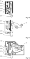
- the carriage 20 of the first drive unit 12 is moved by means of the electric motor 25, for example into the Fig. 3 to 5 shown rest position in its example in the Fig. 6, 7a and 7b shown gripping position transferred. Furthermore, the hook 26 is automatically transferred again from its non-actuation position to its actuation position by means of the electric motor 32. See the Fig. 5 and 6 in the synopsis.
- the door 10 In order to transfer the door 10 from their in the Fig. 1 shown opening position in the Fig. 3 In the closed position shown, for example in order to start a cooking process in the cooking chamber 6, the door 10 is first automatically moved by means of the second drive unit 14 from its open position, i.e. at approximately 85° door opening, to approximately 3° door opening. See the Fig. 7a , in which the door 10 is shown at approximately 3° door opening. At approximately 3° door opening, the door 10, namely the undercut 28 of the door 10 formed at the opening 30, comes into engagement with the hook 26.
- the door 10 pushes the hook 26 away from the actuation position against the above-mentioned spring force of the spring element, not shown of the hook 26 initially in the direction of the non-actuation position of the hook 26, so that the hook 26 comes into engagement with the undercut 28 of the door 10 when it is automatically returned to its actuation position by means of the spring force of the aforementioned spring element. See the Fig. 7b .
- the operating position of the hook 26 and the contact of the door 10 on the carriage 22 are, analogous to above, detected by means of the switches 36 and 38.
- the door 10 is now no longer moved in the direction of its closed position with the second drive unit 14, but rather by means of the first drive unit 12.
- the carriage 20 is automatically moved from it into the position by means of the electric motor 25 Fig. 6 to 7b shown gripping position in its in the Fig. 3 to 5 shown rest position, so that the door 10 is moved from approximately 3° door opening to 0° door opening, i.e. in the first movement section when the door 10 is transferred from its open position to its closed position, by means of the first drive unit 12.
- the first drive unit 12 pulls the door 10 against the above-mentioned sealing device in such a way that the door 10 lies tightly against the sealing device, not shown, in its closed position. Please refer Fig. 3 .
- the rest position of the carriage 20 is by means of the switch 34, the actuation position of the hook 26 by means of the Switch 36, the contact of the door 10 on the carriage 20 by means of the switch 38 and the closed position of the door 10 by means of the aforementioned switch 38 in combination with the switch 40 can be detected.
- the cooking appliance 2 also has a so-called rapid cooling function.
- this rapid cooling function By means of this rapid cooling function, it is possible to cool down the cooking chamber 6 in a shorter time by automatically moving the door 10 into an intermediate position between the open position and the closed position of the door 10.
- an automatic program for the rapid cooling function of the cooking chamber 6 is stored, the door 10 being automatically transferred to an intermediate position corresponding to this automatic program when the automatic program is executed.
- the door 10 is transferred from its closed position to the aforementioned intermediate position automatically by means of the second drive unit 14, the door 10 being automatically held in this intermediate position.
- This intermediate layer can, for example, be used as the one in the Fig. 7b
- the position of the door 10 shown and already explained above can be formed. Accordingly, if the automatic program for the rapid cooling function is selected manually or automatically, the hook 26 would remain positioned in its operating position, in contrast to the above statements for transferring the door 10 from its closed position to its open position. The mutually corresponding coupling means 26, 28 of the door 10 and the first drive unit 12 thus remain in engagement with one another. The door 10 is moved from its closed position 10 to its closed position by means of the second drive unit 14 Fig. 7b shown intermediate layer transferred.
- the door 10 can also be automatically transferred to at least one intermediate position for other cooking appliance functions. For this purpose, in contrast to the example case explained, it may be necessary to move the hook into its non-actuated position.
- a second exemplary embodiment of a cooking appliance according to the invention and the method according to the invention is shown purely as an example.
- components that are the same or have the same effect are in the Fig. 13 to 16c with the same reference numbers as in the Fig. 1 to 12 designated.
- the cooking appliance 2 is also designed as a household oven and comprises a housing 4, a cooking chamber 6 arranged in the housing 4 with a cooking chamber opening 8 and a door 10 assigned to the cooking chamber opening 8, the door 10 being in a range of movement between one and the other Fig. 14 and 16a to 16c corresponding closed position and one in the Fig. 13 shown and to the Fig. 15a and 15b corresponding opening position of the door 10 can be moved.
- the cooking space 6, namely the cooking space opening 8, is essentially tightly closed in the closed position of the door 10 and accessible in the open position of the door 10, with a first drive unit 12 and a second drive unit 14 on the housing 4 each for the automatic movement of the door 10 are arranged, and wherein the door 10 can be moved by means of the first drive unit 12 in a first movement section of the range of movement and by means of the second drive unit 14 in a second movement section of the range of movement of the door 10.
- the door 10 is in the first movement section of the movement range by means of the first drive unit 12 in the first movement section of the movement range and by means of the second drive unit 14 in the second movement section of the movement range, depending on the transfer of the door 10 into its open position or into its closed position
- Door 10 is movable, which will be explained in more detail below.
- the door 10 is arranged to be pivotable about a rotation axis 16 arranged on the housing 4, the first drive unit 12 and the second drive unit 14 being connected to the door 10 on the rotation axis side in a force-transmitting manner. See the Fig. 14 .
- the first movement section of the door 10 ranges from 0° to approximately 3° door opening, with 0° door opening corresponding to the closed position of the door 10.
- the second movement section of the door 10 ranges from about 3° to about 85° door opening, with 85° door opening being the one in the Fig. 13 shown opening position of the door 10 corresponds.
- the first movement section is therefore positioned on the closing position side and the second movement section is positioned on the opening position side.
- the first drive unit 12 and the second drive unit 14 are each connected to the door 10 in a force-transmitting manner for the automatic movement of the door 10 by means of a common coupling device 50.
- the coupling device 50 comprises a lever 51 which is connected to the door 10 of the cooking appliance 2 in a force-transmitting manner known to those skilled in the art. See the Fig. 14 , in which, however, only the mechanism of the door 10 connected to the coupling device 50 in a torque-transmitting manner is shown.
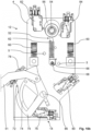
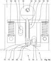
- the first drive unit 12 has a force introduction device 52, the force introduction device 52 being between one in the Fig. 16a to 16c illustrated engagement position, in which the force introduction device 52 is in force-transmitting engagement with the coupling device 50, and one in the Fig. 15a and 15b shown non-engagement position, in which the force introduction device 52 is not in force-transmitting engagement with the coupling device 50, can be moved back and forth.
- the view in the Fig. 15b differs from the view in the Fig. 15a simply because in the Fig. 15b the carriage 58 is not shown in order to be able to see the force introduction device 52.
- the carriage 58 is partially shown.
- the first drive unit 12 has a motor 54, for example an electric motor, an eccentric 56 connected to the motor 54 in a torque-transmitting manner, and a slide 58, the slide 58 being resiliently mounted on the housing 4 by means of two return springs 60 that the force introduction device 52 mounted on the carriage 58 can be automatically moved from its engaged position to its non-engaged position by means of the return springs 60, and the motor 54, the eccentric 56 and the carriage 58 are designed and arranged relative to one another in such a way that the ones on the carriage 58 mounted force introduction device 52 can be automatically moved from its non-engaged position into its engaged position by means of the motor 54, the eccentric 56 and the slide 58.
- a motor 54 for example an electric motor
- an eccentric 56 connected to the motor 54 in a torque-transmitting manner
- a slide 58 being resiliently mounted on the housing 4 by means of two return springs 60 that the force introduction device 52 mounted on the carriage 58 can be automatically moved from its engaged position to its non-engaged position by means of the return
- the carriage 58 is guided on the housing 4 by means of mutually corresponding guide means 5, 59, the guide means of the housing 4 being designed as two guide bolts 5 and the corresponding guide means of the carriage 58 being designed as two elongated holes 59 arranged parallel to one another. See for example the Fig. 15a .
- the force introduction device 52 is resiliently mounted on the carriage 58 by means of a force introduction spring 62, namely such that a range of movement of the force introduction device 52 relative to the carriage 58 is limited by means of mutually corresponding limiting means 64, 66 of the force introduction device 52 and the carriage 58.
- the mutually corresponding limiting means 64, 66 are designed as an elongated hole 64 in the carriage 58 and a bolt 66 of the force introduction device 52 corresponding to the elongated hole 64. See also for example that Fig. 15a and 15b in the synopsis.
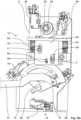
- An impeller 68 is arranged on the bolt 66, which is rotatably arranged on the rest of the force introduction device 52, so that the force introduction device 52 can roll with little friction in its engaged position on the coupling device 50. See for example the Fig. 16a to 16c in the synopsis. In the Fig. 16c The impeller 68 appears more like a polygon in cross section; In practice, however, the impeller 68 has a circular running surface.
- the coupling device 50 For the purpose of transmitting force between the first drive unit 12 on one side and the coupling device 50 on the other side, in the engaged position of the force introduction device 52, the coupling device 50 has a coupling link 70, the force introduction device 52 of the first drive unit 12 being in its engaged position by means of the Coupling link 70 is engaged with the coupling device 50, namely such that the coupling link 70 has a coupling link slope 72 for redirecting a force introduced into the coupling device 50 by means of the force introduction device 52. See the Fig. 16b and 16c .
- the coupling device 50 has a control link 74, the control link 74 being designed to actuate a total of three switches 76, 78, 80 which are connected to a control 7 of the cooking appliance 2 in a signal-transmitting manner, namely that by means of the control link 74, the plurality of switches 76, 78, 80 can be actuated in such a way that the opening position of the door 10, the closed position of the door 10 and an intermediate position of the door 10 can be detected by means of the individual switches 76, 78, 80, the first movement section between the intermediate position and the closed position of the door 10 and the second movement section is formed between the intermediate layer and the opening position of the door 10.
- the switch 76 is used to detect the open position of the door 10
- the switch 78 is used to detect the intermediate position of the door 10
- the switch 80 is used to detect the closed position of the door 10.
- the force introduction device 52 of the first drive unit 12 is in the present exemplary embodiment Depending on the detection of the intermediate layer during the transfer of the door 10 into its closed position, it can be transferred from its non-engaged position into its engaged position, which is explained in more detail below.
- the switches 82 and 84 both serve to detect a rotational position of the eccentric 56, the switches 82, 84 and the eccentric 56 being designed and arranged relative to one another in such a way that both switches 82, 84 can be actuated simultaneously by means of the eccentric 56 when the eccentric 56 in one in the Fig. 16a to 16c shown position, which corresponds to the engagement position of the force introduction device 52.
- neither of the two switches 82, 84 can be actuated by means of the eccentric 56 when the eccentric 56 is in one in the Fig. 15a , 15b shown position, which corresponds to the non-engaged position of the force introduction device 52.
- the second drive unit 14 is continuously connected to the coupling device 50 in a force-transmitting manner.
- a motor 86 for example an electric motor, of the second drive unit 14 is connected to the coupling link 70 in a torque-transmitting manner. See for example the Fig. 14 and 15a in the synopsis.
- the door 10 of the cooking appliance 2 is initially in its position Fig. 16a to 16c corresponding closed position, so that the cooking space opening 8 and thus the cooking space 6 is closed.
- the door 10 is held by means of the first drive unit 12 with the force introduction device 52 and the coupling link 70 of the coupling device 50, so that the door 10 is effectively secured against unwanted automatic opening.
- a user In order to transfer the door 10 from its closed position to its closed position Fig. 13 In the opening position shown, a user, not shown, of the cooking appliance 2 in the present exemplary embodiment operates a button in the Fig. 13 to 16c Control element, not shown, of the cooking appliance 2. For example, the user presses a control element designed as a push button. However, other controls are also conceivable.
- the transfer of the door 10 from its closed position to its open position can also be initiated automatically. For example, a program sequence of an automatic program stored in the control 7 of the cooking appliance 2 provides for such an automatic transfer of the door 10.
- the force introduction device 52 is first moved from its engagement position according to Fig. 16a to 16c in theirs Non-intervention situation according to the Fig. 15a and 15b transferred.
- the motor 54 of the first drive unit 12 is controlled accordingly by means of the controller 7, so that the motor 54 moves the eccentric 56 from it to the Fig. 16a to 16c corresponding rotational position in its to the Fig. 15a and 15b transferred to the corresponding rotational position.
- the motor 54 of the first drive unit 12 is then switched off using the controller 7. Due to the spring force of the two return springs 60, the carriage 58 and thus the force introduction device 52 arranged on the carriage 58 is in the respective image plane Fig. 15a to 16c moved upwards. The ones to the Fig. 15a and 15b
- the corresponding rotational position of the eccentric 56 is detected in the manner explained above by means of the two switches 82, 84 and forwarded to the controller 7.
- the door 10 is now moved further by means of the second drive unit 14 from a position of the door 10 located between the closed position and the intermediate layer, via the intermediate layer in the Fig. 13 shown opening position transferred.
- the door 10 is balanced in such a way that very little force is required to transfer the door 10 from its closed position to its open position, i.e. over the entire range of movement of the door 10 in the direction of the open position.
- the motor 86 of the second drive unit 14 can be designed to be weak and therefore inexpensive.
- the opening position of the door 10 can be detected using the switch 76, as explained above.
- the door 10 is first automatically moved by means of the second drive unit 14 from its opening position, i.e. at approximately 85 ° door opening, to approximately 3 ° door opening.
- the door 10 is in its intermediate position, which is detected by means of the switch 78 and forwarded to the control 7.
- the controller 7 then switches off the motor 86 of the second drive unit 14, so that the door 10 is no longer moved with the second drive unit 14 in the direction of its closed position.
- the controller 7 controls the motor 54 in a manner known to those skilled in the art in such a way that the motor 54 moves the eccentric 56 from it into the Fig. 15a and 15b shown rotational position in its in the Fig. 16a to 16c shown rotation position transferred.
- the motor 54 moves the eccentric 56 in the image plane Fig. 15a turns left or right.
- the eccentric 56 presses the carriage 58 against the spring force of the two return springs 60 in the respective image plane Fig. 15a to 16c downward, so that the force introduction device 52 arranged on the carriage 58 is transferred from its non-engaged position into its engaged position and comes into force-transmitting engagement with the coupling link 70.
- the Force introduction device 52 presses against the coupling link slope 72 by means of the impeller 68, so that the force introduced into the coupling link 70 by means of the force introduction device 52 is deflected in such a way that the door 10 essentially seals the cooking chamber opening 8 of the cooking chamber 6 by means of the coupling device 50.
- the door 10 is thus moved from approximately 3° door opening to 0° door opening, i.e. in the first movement section when the door 10 is transferred from its open position to its closed position, by means of the first drive unit 12.
- the first drive unit 12 presses the door 10 by means of the force introduction device 52, for example, against the above-mentioned sealing device, not shown, in such a way that the door 10 lies tightly against the sealing device, not shown, in its closed position. Accordingly, the higher force required for this and applied by the first drive unit 12, namely the contact force against the aforementioned sealing device, is only required over the small first movement section. Due to the favorable arrangement of the first drive unit 12 in terms of power transmission, it is nevertheless possible to reduce the required power of the first drive unit 12 to a minimum.
- the door 10 Due to the resilient contact of the force introduction device 52 arranged on the carriage 58 on the coupling device 50, namely the coupling link 70, in the engaged position of the force introduction device 52, the door 10, when the force introduction device 52 is in the engaged position, is against a spring force of the force introduction spring 62, for example from the user of the cooking appliance 2, not shown, can be manually moved from its closed position to its open position.
- the force introduction device 52 moves relative to the carriage 58 in its range of motion limited by the limiting means 64, 66 of the carriage 58 and the force introduction device 52.
- the invention can also be used advantageously in other cooking appliances, such as steamers, microwave ovens or combination appliances with a plurality of different types of heating.
- the invention can also be used in the professional sector, i.e. in commercial cooking appliances.
- the cooking appliance according to the invention according to the second exemplary embodiment can, analogous to the first exemplary embodiment, also have a so-called rapid cooling function.
- an automatic program for the rapid cooling function of the cooking space is stored in the control of the cooking appliance, with the door being automatically transferred to an intermediate position corresponding to this automatic program when the automatic program is executed.
- the door is transferred from its closed position to the aforementioned intermediate position automatically, for example, by means of the second drive unit, with the door being automatically held in this intermediate position.
- the door can also be automatically transferred to at least one intermediate position for other cooking appliance functions.
- the door 10 in the engaged position of the force introduction device 52, the door 10, with the force introduction device 52 in the engaged position, can be manually moved from its closed position to its open position against a spring force of the force introduction spring 62, for example by the user of the cooking appliance 2, not shown.
- the force introduction device 52 moves relative to the carriage 58 in its range of motion limited by the limiting means 64, 66 of the carriage 58 and the force introduction device 52.
- the invention is not limited to the present exemplary embodiments of the cooking appliance according to the invention and the method according to the invention.
- the invention can also be used advantageously in other cooking appliances, such as steamers, microwave ovens or combination appliances with a plurality of different types of heating.
- the invention can also be used in the professional sector, i.e. in commercial cooking appliances.
- the door can be moved by means of the first drive unit in a first movement section of the range of movement and by means of the second drive unit in a second movement section of the range of movement of the door, regardless of whether the door is in its open position or in whose closed position is transferred.
- embodiments with other dependencies are also possible when transferring the door from its open position to its closed position or vice versa, as well as when transferring the door from the open position or its closed position into an intermediate layer positioned between the open position and the closed position. The same applies to a transfer from one intermediate layer of the door to a different intermediate layer of the door.
- the cooking appliance according to the invention according to the second exemplary embodiment can, analogous to the first exemplary embodiment, also have a so-called rapid cooling function.
- an automatic program for the rapid cooling function of the cooking space is stored in the control of the cooking appliance, with the door being automatically transferred to an intermediate position corresponding to this automatic program when the automatic program is executed.
- the door is transferred from its closed position to the aforementioned intermediate position automatically, for example, by means of the second drive unit, with the door being automatically held in this intermediate position.
- the door can also be automatically transferred to at least one intermediate position for other cooking appliance functions.
Description
Die Erfindung betrifft ein Gargerät, umfassend ein Gehäuse, einen in dem Gehäuse angeordneten Garraum mit einer Garraumöffnung und eine der Garraumöffnung zugeordnete Tür, wobei die Tür um eine an dem Gehäuse angeordnete Drehachse in einem Bewegungsbereich zwischen einer Schließlage und einer Öffnungslage der Tür schwenkbar ist, und wobei der Garraum in der Schließlage der Tür verschlossen und in der Öffnungslage der Tür zugänglich ist.The invention relates to a cooking appliance comprising a housing, a cooking chamber arranged in the housing with a cooking chamber opening and a door assigned to the cooking chamber opening, the door being pivotable about a rotation axis arranged on the housing in a range of movement between a closed position and an open position of the door, and wherein the cooking chamber is closed in the closed position of the door and accessible in the open position of the door.
Derartige Gargeräte und Verfahren zu deren Betrieb sind aus dem Stand der Technik in einer Vielzahl von Ausführungsformen bereits vorbekannt, beispielsweise aus der
Die
Aus der
Der Erfindung stellt sich somit das Problem, ein Gargerät der eingangs genannten Art anzugeben, bei denen der Türbetätigungsmechanismus und die Türbetätigung verbessert sind.The invention therefore faces the problem of providing a cooking appliance of the type mentioned in which the door operating mechanism and the door operation are improved.
Erfindungsgemäß wird dieses Problem durch ein Gargerät mit den Merkmalen des Patentanspruchs 1 gelöst.According to the invention, this problem is solved by a cooking appliance with the features of patent claim 1.
Vorteilhafte Ausgestaltungen und Weiterbildungen der Erfindung ergeben sich aus den nachfolgenden Unteransprüchen.Advantageous refinements and further developments of the invention result from the following subclaims.
Der mit der Erfindung erreichbare Vorteil besteht insbesondere darin, dass bei einem Gargerät, umfassend ein Gehäuse, einen in dem Gehäuse angeordneten Garraum mit einer Garraumöffnung und eine der Garraumöffnung zugeordnete Tür, sowie bei einem Verfahren zu dessen Betrieb der Türbetätigungsmechanismus und die Türbetätigung verbessert sind. Bei Gargeräten mit einem durch eine Tür verschließbaren Garraum ist es wichtig, dass die Garraumöffnung des Garraums beispielsweise während eines Garvorgangs mittels der Tür dicht verschließbar ist. Gleiches gilt auch für einen in dem Garraum ablaufenden Reinigungsvorgang, wie eine pyrolytische Reinigung des Garraums oder dergleichen. In all diesen Fällen ist es erforderlich, dass die Garraumöffnung mittels der Tür dicht verschlossen ist, um ein ungewünschtes Austreten von Wrasen, Reinigungsdämpfen oder dergleichen aus dem Garraum wirksam zu verhindern. Um dies zu erreichen, ist es notwendig, dass die Tür in deren Schließlage fest gegen eine an der Garraumöffnung umlaufend angeordnete Dichtungsvorrichtung gedrückt wird. Hierfür ist eine hohe Anpresskraft erforderlich, während es für die Bewegung der Tür in deren übrigen Bewegungsbereich lediglich einer geringen Kraft bedarf. Hier setzt die Erfindung an. Anstelle einen einzigen Antrieb für die Tür bereitzustellen, werden erfindungsgemäß zwei Antriebseinheiten verwendet, wobei die Tür mittels der ersten Antriebseinheit in einem ersten Bewegungsabschnitt des Bewegungsbereichs und mittels der zweiten Antriebseinheit in einem zweiten Bewegungsabschnitt des Bewegungsbereichs der Tür bewegbar ist. Hierdurch ist es möglich, schwächere und damit kostengünstigere Elektromotoren für die jeweilige Antriebseinheit zu verwenden.The advantage that can be achieved with the invention is, in particular, that in a cooking appliance comprising a housing, a cooking chamber arranged in the housing with a cooking chamber opening and a door assigned to the cooking chamber opening, as well as in a method for its operation, the door operating mechanism and the door actuation are improved. In the case of cooking appliances with a cooking space that can be closed by a door, it is important that the cooking space opening of the cooking space can be tightly closed by means of the door, for example during a cooking process. The same also applies to a cleaning process taking place in the cooking space, such as pyrolytic cleaning of the cooking space or the like. In all of these cases, it is necessary that the cooking chamber opening is tightly closed by means of the door in order to effectively prevent unwanted escape of vapors, cleaning vapors or the like from the cooking chamber. In order to achieve this, it is necessary that the door is pressed firmly in its closed position against a sealing device arranged all around the cooking chamber opening. A high contact pressure is required for this, while only a small amount of force is required to move the door in its remaining range of motion. This is where the invention comes into play. Instead of providing a single drive for the door, according to the invention two drive units are used, the door being movable by means of the first drive unit in a first movement section of the range of movement and by means of the second drive unit in a second movement section of the range of movement of the door. This makes it possible to use weaker and therefore more cost-effective electric motors for the respective drive unit.
In der bevorzugten Ausführungsform, wonach die Tür in Abhängigkeit der Überführung der Tür in deren Öffnungslage oder in deren Schließlage mittels der ersten Antriebseinheit in einem ersten Bewegungsabschnitt des Bewegungsbereichs und mittels der zweiten Antriebseinheit in einem zweiten Bewegungsabschnitt des Bewegungsbereichs der Tür bewegbar ist, werden ferner die Besonderheiten bei der Überführung der Tür in deren Öffnungslage und in deren Schließlage in vorteilhafter Weise berücksichtigt. Beispielsweise ist die oben genannte hohe Anpresskraft bei der Bewegung der Tür lediglich bei deren Überführung in deren Schließlage erforderlich. Entsprechend ist es nach der vorgenannten bevorzugten Ausführungsform der Erfindung möglich, dass die Tür nicht nur in dem zweiten Bewegungsabschnitt mittel der zweiten Antriebseinheit bewegbar ist und bewegt wird, sondern auch in dem ersten Bewegungsabschnitt, nämlich bei der Überführung der Tür in deren Öffnungslage. Jedoch ist diese Ausbildung der Erfindung rein exemplarisch zu verstehen.In the preferred embodiment, according to which the door can be moved depending on the transfer of the door into its open position or into its closed position by means of the first drive unit in a first movement section of the range of movement and by means of the second drive unit in a second movement section of the range of movement of the door, the Special features when transferring the door into its open position and into its closed position are advantageously taken into account. For example, the above-mentioned high contact pressure when moving the door is only required when it is transferred to its closed position. Accordingly, according to the aforementioned preferred embodiment of the invention, it is possible for the door to be movable and moved not only in the second movement section by means of the second drive unit, but also in the first Movement section, namely when the door is transferred to its open position. However, this embodiment of the invention is to be understood purely as an example.
Grundsätzlich ist die Ausbildung der Türbetätigungsmechanik in weiten geeigneten Grenzen frei wählbar. Die Ausbildung des erfindungsgemäßen Gargeräts sieht vor, dass die Tür um eine an dem Gehäuse angeordnete Drehachse schwenkbar angeordnet ist. Außerdem sind die erste Antriebseinheit und die zweite Antriebseinheit jeweils zur automatischen Bewegung der Tür mittels einer gemeinsamen Kopplungsvorrichtung mit der Tür kraftübertragend verbunden. Aufgrund dieser Weiterbildung des Gargeräts und des Verfahrens zu dessen Betrieb, wonach die erste und die zweite Antriebseinheit jeweils zur automatischen Bewegung der Tür mittels einer gemeinsamen Kopplungsvorrichtung mit der Tür kraftübertragend verbunden sind und die erste Antriebseinheit und die zweite Antriebseinheit jeweils mittels dieser gemeinsamen Kopplungsvorrichtung die Tür automatisch bewegen, ist eine besonders einfache und damit kostengünstige Ausbildung des Gargeräts ermöglicht. Dabei sind die erste Antriebseinheit und die zweite Antriebseinheit mittels der Kopplungsvorrichtung drehachsenseitig mit der Tür kraftübertragend verbunden. Auf diese Weise ist beispielsweise eine kompakte und damit platzsparende Anordnung der Türbetätigungsmechanik ermöglicht. Ferner ist das erfindungsgemäße Gargerät damit in bauteilsparender Art und Weise realisierbar.In principle, the design of the door operating mechanism can be freely selected within wide, suitable limits. The design of the cooking appliance according to the invention provides that the door is arranged to be pivotable about an axis of rotation arranged on the housing. In addition, the first drive unit and the second drive unit are each connected to the door in a force-transmitting manner for the automatic movement of the door by means of a common coupling device. Due to this development of the cooking appliance and the method for its operation, according to which the first and second drive units are each connected to the door in a force-transmitting manner for the automatic movement of the door by means of a common coupling device and the first drive unit and the second drive unit are each connected to the door by means of this common coupling device move automatically, a particularly simple and therefore cost-effective design of the cooking appliance is possible. The first drive unit and the second drive unit are connected to the door on the rotation axis side in a force-transmitting manner by means of the coupling device. In this way, for example, a compact and therefore space-saving arrangement of the door operating mechanism is made possible. Furthermore, the cooking appliance according to the invention can therefore be implemented in a way that saves components.
Eine sehr vorteilhafte Weiterbildung des erfindungsgemäßen Gargeräts sieht vor, dass die erste Antriebseinheit eine Krafteinleitungsvorrichtung aufweist, wobei die Krafteinleitungsvorrichtung zwischen einer Eingriffslage, in der die Krafteinleitungsvorrichtung mit der Kopplungsvorrichtung kraftübertragend in Eingriff ist, und einer Nichteingriffslage, in der die Krafteinleitungsvorrichtung mit der Kopplungsvorrichtung kraftübertragend nicht in Eingriff ist, hin und her überführbar ist. Hierdurch ist es möglich, die erste Antriebseinheit mittels der Krafteinleitungsvorrichtung wahlweise mit der Kopplungsvorrichtung kraftübertragend zu verbinden oder diese Kraftübertragungsverbindung zu lösen. Die erste Antriebseinheit kann beispielsweise mittels der Krafteinleitungsvorrichtung lediglich für den Fall kraftübertragend mit der Kopplungsvorrichtung verbunden sein, wenn die oben genannte hohe Anpresskraft der Tür für ein dichtes Verschließen der Garraumöffnung des Garraums erforderlich ist. Ansonsten kann die erste Antriebseinheit auf die vorgenannte Weise von der Kopplungsvorrichtung entkoppelt sein, so dass eine sonstige Bewegung der Tür, manuell oder automatisch, wesentlich erleichtert ist.A very advantageous development of the cooking appliance according to the invention provides that the first drive unit has a force introduction device, the force introduction device being between an engagement position in which the force introduction device is in force-transmitting engagement with the coupling device, and a non-engagement position in which the force introduction device is not force-transmitting with the coupling device is engaged, can be transferred back and forth. This makes it possible to either connect the first drive unit to the coupling device in a force-transmitting manner by means of the force introduction device or to release this force transmission connection. The first drive unit can, for example, be connected to the coupling device in a force-transmitting manner by means of the force introduction device only in the case when the above-mentioned high contact pressure of the door is required for a tight closure of the cooking chamber opening of the cooking chamber. Otherwise, the first drive unit can be decoupled from the coupling device in the aforementioned manner, so that any other movement of the door, manually or automatically, is significantly facilitated.
Entsprechend sieht eine vorteilhafte Weiterbildung des erfindungsgemäßen Verfahrens vor, dass die erste Antriebseinheit ein Krafteinleitungsvorrichtung aufweist, wobei die Krafteinleitungsvorrichtung zwischen einer Eingriffslage, in der die Krafteinleitungsvorrichtung mit der Kopplungsvorrichtung kraftübertragend in Eingriff ist, und einer Nichteingriffslage, in der die Krafteinleitungsvorrichtung mit der Kopplungsvorrichtung kraftübertragend nicht in Eingriff ist, hin und her überführt wird.Accordingly, an advantageous development of the method according to the invention provides that the first drive unit has a force introduction device, the force introduction device being between an engagement position in which the force introduction device is in force-transmitting engagement with the coupling device, and a non-engagement position in which the force introduction device is not in force-transmitting engagement with the coupling device and is transferred back and forth.
Eine vorteilhafte Weiterbildung der vorgenannten Ausführungsform des erfindungsgemäßen Gargeräts sieht vor, dass die erste Antriebseinheit zusätzlich einen Motor, einen mit dem Motor drehmomentübertragend verbundenen Exzenter und einen Schlitten aufweist, wobei der Schlitten an dem Gehäuse mittels mindestens einer Rückstellfeder derart federnd gelagert ist, dass die an dem Schlitten gelagerte Krafteinleitungsvorrichtung mittels der Rückstellfeder selbsttätig von deren Eingriffslage in deren Nichteingriffslage überführbar ist, und wobei der Motor, der Exzenter und der Schlitten derart ausgebildet und zueinander angeordnet sind, dass die an dem Schlitten gelagerte Krafteinleitungsvorrichtung mittels des Motors, des Exzenters und des Schlittens von deren Nichteingriffslage automatisch in deren Eingriffslage überführbar ist. Auf diese Weise ist die erste Antriebseinheit konstruktiv und fertigungstechnisch besonders einfach realisierbar. Die Lagerung des Schlittens an dem Gehäuse kann dabei direkt oder indirekt ausgebildet sein. Beispielsweise ist es möglich, dass die erste Antriebseinheit die zweite Antriebseinheit zumindest teilweise als eine Baugruppe ausgebildet sind/ist, die dann als Ganzes mit dem Gehäuse kraftübertragend verbunden ist. Entsprechend kann der Schlitten an einem Montageblech oder dergleichen dieser Baugruppe federnd gelagert sein.An advantageous development of the aforementioned embodiment of the cooking appliance according to the invention provides that the first drive unit additionally has a motor, an eccentric connected to the motor in a torque-transmitting manner and a carriage, the carriage being resiliently mounted on the housing by means of at least one return spring in such a way that the The force introduction device mounted on the carriage can be automatically transferred from its engaged position to its non-engaged position by means of the return spring, and the motor, the eccentric and the carriage are designed and arranged in relation to one another in such a way that the force introduction device mounted on the carriage can be moved by means of the motor, the eccentric and the carriage from their non-intervention position can be automatically transferred to their engagement position. In this way, the first drive unit can be implemented particularly easily in terms of construction and production technology. The carriage can be mounted on the housing directly or indirectly. For example, it is possible for the first drive unit and the second drive unit to be at least partially designed as an assembly, which is then connected as a whole to the housing in a force-transmitting manner. Accordingly, the carriage can be resiliently mounted on a mounting plate or the like of this assembly.
Eine vorteilhafte Weiterbildung der letztgenannten Ausführungsform des erfindungsgemäßen Gargeräts sieht vor, dass die Krafteinleitungsvorrichtung an dem Schlitten mittels mindestens einer Krafteinleitungsfeder federnd gelagert ist, wobei ein Bewegungsbereich der Krafteinleitungsvorrichtung relativ zu dem Schlitten mittels zueinander korrespondierender Begrenzungsmittel der Krafteinleitungsvorrichtung und des Schlittens begrenzt ist. Hierdurch ist eine federnde Anlage der an dem Schlitten angeordneten Krafteinleitungsvorrichtung an der Kopplungsvorrichtung, in der Eingriffslage der Krafteinleitungsvorrichtung, ermöglicht. Entsprechend ist die Tür bei in der Eingriffslage befindlicher Krafteinleitungsvorrichtung gegen eine Federkraft der Krafteinleitungsfeder beispielsweise von einem Benutzer des Gargeräts manuell von deren Schließlage in deren Öffnungslage überführbar.An advantageous development of the last-mentioned embodiment of the cooking appliance according to the invention provides that the force introduction device is resiliently mounted on the carriage by means of at least one force introduction spring, with a range of movement of the force introduction device relative to the carriage being limited by means of mutually corresponding limiting means of the force introduction device and the carriage. This enables the force introduction device arranged on the carriage to rest resiliently on the coupling device in the engaged position of the force introduction device. Correspondingly, when the force introduction device is in the engaged position, the door can be manually moved from its closed position to its open position against a spring force of the force introduction spring, for example by a user of the cooking appliance.
Eine vorteilhafte Weiterbildung des erfindungsgemäßen Gargeräts sieht vor, dass die Kopplungsvorrichtung eine Kopplungskulisse aufweist, wobei die Krafteinleitungsvorrichtung der ersten Antriebseinheit in deren Eingriffslage mittels der Kopplungskulisse mit der Kopplungsvorrichtung in Eingriff ist, bevorzugt, dass die Kopplungskulisse eine Kopplungskulissenschräge zur Umleitung einer mittels der Krafteinleitungsvorrichtung in die Kopplungsvorrichtung eingeleiteten Kraft aufweist. Auf diese Weise ist der konstruktive Aufbau des erfindungsgemäßen Gargeräts weiter vereinfacht. Darüber hinaus hat die bevorzugte Ausführungsform dieser Weiterbildung zusätzlich den Vorteil, dass die mittels der Krafteinleitungsvorrichtung in die Kopplungsvorrichtung eingeleitete Kraft mittels der Kopplungskulissenschräge auf einfache und robuste Art umleitbar ist. Entsprechend ist die erste Antriebseinheit relativ zu der Kopplungsvorrichtung flexibler und freier anordenbar, so dass der in dem jeweiligen erfindungsgemäßen Gargerät vorhandene Bauraum auf die Erfordernisse des Einzelfalls angepasst nutzbar ist.An advantageous development of the cooking appliance according to the invention provides that the coupling device has a coupling link, the force introduction device of the first drive unit in its engaged position being in engagement with the coupling device by means of the coupling link, preferably that the coupling link has a coupling link slope for redirecting a force introduction device into the Coupling device has force introduced. In this way, the structural design of the cooking appliance according to the invention is further simplified. In addition, the preferred embodiment of this development has the additional advantage that by means of the Force introduction device into the coupling device can be redirected in a simple and robust manner by means of the coupling link slope. Accordingly, the first drive unit can be arranged more flexibly and freely relative to the coupling device, so that the installation space available in the respective cooking appliance according to the invention can be used in a manner adapted to the requirements of the individual case.
Eine vorteilhafte Weiterbildung des erfindungsgemäßen Gargeräts sieht vor, dass die Kopplungsvorrichtung eine Steuerkulisse aufweist, wobei die Steuerkulisse zur Betätigung von mindestens einem mit einer Steuerung des Gargeräts signalübertragend verbundenen Schalter ausgebildet ist, bevorzugt, dass mittels der Steuerkulisse eine Mehrzahl von Schaltern betätigbar ist, wobei mittels der einzelnen Schalter die Öffnungslage der Tür, die Schließlage der Tür und eine Zwischenlage der Tür detektierbar ist, und wobei der erste Bewegungsabschnitt zwischen der Zwischenlage und der Schließlage der Tür und der zweite Bewegungsabschnitt zwischen der Zwischenlage und der Öffnungslage der Tür ausgebildet ist. Hierdurch ist eine Detektion mindestens einer Lage der Tür auf konstruktiv und schaltungstechnisch einfache und robuste Weise realisierbar. Darüber hinaus ist die bevorzugte Ausführungsform dieser Weiterbildung besonders vorteilhaft, da damit unter anderem die für die Ansteuerung der ersten und der zweiten Antriebseinheit für die automatische Bewegung der Tür wichtigen Lagen der Tür detektierbar sind. Die vorgenannte Detektion der mindestens einen Lage der Tür ist selbstverständlich auch für andere Funktionen des Gargeräts, beispielsweise für Garfunktionen oder eine Pyrolysefunktion des Gargeräts, in der Steuerung des Gargeräts verwendbar.An advantageous development of the cooking appliance according to the invention provides that the coupling device has a control link, the control link being designed to actuate at least one switch connected to a control of the cooking appliance in a signal-transmitting manner, preferably that a plurality of switches can be actuated by means of the control link, wherein by means of of the individual switches, the open position of the door, the closed position of the door and an intermediate position of the door can be detected, and wherein the first movement section is formed between the intermediate layer and the closed position of the door and the second movement section is formed between the intermediate layer and the open position of the door. This makes it possible to detect at least one position of the door in a simple and robust manner in terms of design and circuitry. In addition, the preferred embodiment of this development is particularly advantageous since, among other things, the positions of the door that are important for controlling the first and second drive units for the automatic movement of the door can be detected. The aforementioned detection of the at least one position of the door can of course also be used for other functions of the cooking appliance, for example for cooking functions or a pyrolysis function of the cooking appliance, in the control of the cooking appliance.
Eine vorteilhafte Weiterbildung der letztgenannten Ausführungsform des erfindungsgemäßen Gargeräts sieht vor, dass die Krafteinleitungsvorrichtung der ersten Antriebseinheit in Abhängigkeit der Detektion der Zwischenlage von deren Eingriffslage in deren Nichteingriffslage und/oder von deren Nichteingriffslage in deren Eingriffslage überführbar ist. Auf diese Weise ist die Ansteuerung der ersten Antriebseinheit mittels der Steuerung des Gargeräts auf besonders sinnfällige Art realisiert. Beispielsweise ist es sinnvoll, wenn die Zwischenlage als die Lage der Tür ausgebildet ist, in der die Tür gerade an einer die Garraumöffnung umlaufend umgebenden Dichtungsvorrichtung anliegt, also in Kontakt mit der vorgenannten Dichtungsvorrichtung ist, ohne diese Dichtungsvorrichtung wesentlich zu komprimieren. Sobald diese Zwischenlage der Tür während der Überführung der Tür in deren Schließlage auf die vorgenannte Weise detektiert worden ist, kann dann die Krafteinleitungsvorrichtung der ersten Antriebseinheit von deren Nichteingriffslage in deren Eingriffslage überführt werden, so dass die Tür mittels der ersten Antriebseinheit und der Kopplungsvorrichtung fest gegen die vorgenannte Dichtungsvorrichtung gedrückt wird, nämlich derart, dass die Garraumöffnung mittels der Tür und der Dichtungsvorrichtung im Wesentlichen dicht verschlossen ist.An advantageous development of the last-mentioned embodiment of the cooking appliance according to the invention provides that the force introduction device of the first drive unit can be transferred from its engaged position to its non-engaged position and/or from its non-engaged position to its engaged position depending on the detection of the intermediate layer. In this way, the control of the first drive unit is realized in a particularly obvious way by means of the control of the cooking appliance. For example, it makes sense if the intermediate layer is designed as the position of the door in which the door is in contact with a sealing device surrounding the cooking space opening, i.e. is in contact with the aforementioned sealing device, without significantly compressing this sealing device. As soon as this intermediate position of the door has been detected during the transfer of the door into its closed position in the aforementioned manner, the force introduction device of the first drive unit can then be transferred from its non-engaged position into its engaged position, so that the door is firmly against by means of the first drive unit and the coupling device the aforementioned sealing device is pressed, namely in such a way that the cooking space opening is essentially tightly closed by means of the door and the sealing device.
Eine andere vorteilhafte Weiterbildung sieht vor, dass der erste Bewegungsabschnitt schließlagenseitig und der zweite Bewegungsabschnitt öffnungslagenseitig positioniert ist. Wie bereits oben ausgeführt, ist insbesondere bei der Überführung der Tür in deren Schließlage eine hohe Betätigungskraft, beispielsweise eine Anpresskraft zur dichten Anlage der Tür an der oben genannten Dichtungsvorrichtung, bei der Betätigung der Tür erforderlich. Entsprechend ist es vorteilhaft, für den dazu korrespondierenden Bewegungsabschnitt in dem Bewegungsbereich der Tür einen Wechsel in der Betätigung der Tür von der zweiten Antriebseinheit zu der ersten Antriebseinheit zu vollziehen.Another advantageous development provides that the first movement section is positioned on the closing position side and the second movement section is positioned on the opening position side. As already stated above, a high actuating force, for example a contact pressure for the door to fit tightly against the above-mentioned sealing device, is required when operating the door, particularly when the door is moved into its closed position. Accordingly, it is advantageous to carry out a change in the actuation of the door from the second drive unit to the first drive unit for the corresponding movement section in the movement range of the door.
Eine weitere vorteilhafte Weiterbildung sieht vor, dass die Tür mittels der ersten Antriebseinheit und/oder der zweiten Antriebseinheit automatisch in mindestens eine Zwischenlage der Tür überführt und in dieser Zwischenlage gehalten wird, wobei die Zwischenlage der Tür zwischen der Schließlage und der Öffnungslage der Tür positioniert ist. Auf diese Weise ist die Tür nicht lediglich zwischen deren Schließlage und deren Öffnungslage automatisch hin und her überführbar. Stattdessen kann die Tür auch mindestens eine Zwischenlage zwischen deren Schließlage und deren Öffnungslage einnehmen.A further advantageous development provides that the door is automatically transferred to at least one intermediate position of the door by means of the first drive unit and/or the second drive unit and is held in this intermediate position, the intermediate layer of the door being positioned between the closed position and the open position of the door . In this way, the door can not only be automatically moved back and forth between its closed position and its open position. Instead, the door can also occupy at least one intermediate position between its closed position and its open position.
Grundsätzlich ist die mindestens eine Zwischenlage der Tür in weiten geeigneten Grenzen frei wählbar. Eine besonders vorteilhafte Weiterbildung des erfindungsgemäßen Verfahrens sieht vor, dass in einer Steuerung des Gargeräts ein Automatikprogramm für ein Schnellabkühlen des Garraums abgespeichert ist, wobei die Tür bei der Ausführung des Automatikprogramms automatisch in eine zu diesem Automatikprogramm korrespondierende Zwischenlage überführt wird. Hierdurch ist eine Schnellabkühlfunktion bei dem erfindungsgemäßen Gargerät ohne zusätzlichen konstruktiven Aufwand ermöglicht.In principle, the at least one intermediate layer of the door can be freely selected within wide, suitable limits. A particularly advantageous development of the method according to the invention provides that an automatic program for rapid cooling of the cooking chamber is stored in a control of the cooking appliance, the door being automatically transferred to an intermediate position corresponding to this automatic program when the automatic program is executed. This enables a rapid cooling function in the cooking appliance according to the invention without additional design effort.
Zwei Ausführungsbeispiele der Erfindung sind in den Zeichnungen rein schematisch dargestellt und werden nachfolgend näher beschrieben. Dabei ist das erste Ausführungsbeispiel nicht erfindungsgemäß. Es zeigen
- Figur 1
- das erste Ausführungsbeispiel des Gargeräts in einer Frontalansicht,
Figur 2- das erste Ausführungsbeispiel in einer geschnittenen Seitenansicht, in teilweiser Darstellung,
- Figur 3
- das erste Ausführungsbeispiel in einer ersten geschnittenen Draufsicht im Bereich der ersten Antriebseinheit, in teilweiser Darstellung,
Figur 4- das erste Ausführungsbeispiel in einer zweiten geschnittenen Draufsicht im Bereich der ersten Antriebseinheit, in teilweiser Darstellung,
Figur 5- das erste Ausführungsbeispiel in einer dritten geschnittenen Draufsicht im Bereich der ersten Antriebseinheit, in teilweiser Darstellung,
Figur 6- das erste Ausführungsbeispiel in einer vierten geschnittenen Draufsicht im Bereich der ersten Antriebseinheit, in teilweiser Darstellung,
- Figur 7a
- das erste Ausführungsbeispiel in einer fünften geschnittenen Draufsicht im Bereich der ersten Antriebseinheit, in teilweiser Darstellung,
- Figur 7b
- das erste Ausführungsbeispiel in einer sechsten geschnittenen Draufsicht im Bereich der ersten Antriebseinheit, in teilweiser Darstellung,
Figur 8- die erste Antriebseinheit des ersten Ausführungsbeispiels in einer Seitenansicht,
- Figur 9
- die erste Antriebseinheit des ersten Ausführungsbeispiels in einer ersten geschnittenen Draufsicht,
Figur 10- die erste Antriebseinheit des ersten Ausführungsbeispiels in einer zweiten geschnittenen Draufsicht,
- Figur 11
- die erste Antriebseinheit des ersten Ausführungsbeispiels in einer dritten geschnittenen Draufsicht,
Figur 12- die erste Antriebseinheit des ersten Ausführungsbeispiels in einer vierten geschnittenen Draufsicht,
- Figur 13
- ein zweites Ausführungsbeispiel eines erfindungsgemäßen Gargeräts in einer Frontalansicht,
Figur 14- das zweite Ausführungsbeispiel in einer perspektivischen Ansicht, in teilweiser Darstellung,
- Figur 15a
- das zweite Ausführungsbeispiel in zwei teilweisen Detailansichten im Bereich
- und 15b
- der ersten und zweiten Antriebseinheit, mit Blickrichtung von außen und
- Figur 16a
- das zweite Ausführungsbeispiel in weiteren drei teilweisen Detailansichten im Bereich
- bis 16c
- der ersten und zweiten Antriebseinheit, mit Blickrichtung von schräg außen und von außen.
- Figure 1
- the first exemplary embodiment of the cooking appliance in a frontal view,
- Figure 2
- the first exemplary embodiment in a sectioned side view, in a partial representation,
- Figure 3
- the first exemplary embodiment in a first sectional plan view in the area of the first drive unit, in a partial representation,
- Figure 4
- the first exemplary embodiment in a second sectional plan view in the area of the first drive unit, in a partial representation,
- Figure 5
- the first exemplary embodiment in a third sectional plan view in the area of the first drive unit, in a partial representation,
- Figure 6
- the first exemplary embodiment in a fourth sectional plan view in the area of the first drive unit, in a partial representation,
- Figure 7a
- the first exemplary embodiment in a fifth sectional plan view in the area of the first drive unit, in a partial representation,
- Figure 7b
- the first exemplary embodiment in a sixth sectional top view in the area of the first drive unit, in a partial representation,
- Figure 8
- the first drive unit of the first exemplary embodiment in a side view,
- Figure 9
- the first drive unit of the first exemplary embodiment in a first sectional top view,
- Figure 10
- the first drive unit of the first exemplary embodiment in a second sectional top view,
- Figure 11
- the first drive unit of the first exemplary embodiment in a third sectional top view,
- Figure 12
- the first drive unit of the first exemplary embodiment in a fourth sectional top view,
- Figure 13
- a second exemplary embodiment of a cooking appliance according to the invention in a front view,
- Figure 14
- the second exemplary embodiment in a perspective view, in a partial representation,
- Figure 15a
- the second exemplary embodiment in two partial detailed views in the area
- and 15b
- the first and second drive units, looking from the outside and
- Figure 16a
- the second exemplary embodiment in another three partial detailed views in the area
- until 16c
- the first and second drive units, looking diagonally from the outside and from the outside.
In den
Die Tür 10 ist um eine an dem Gehäuse 4 angeordnete Drehachse 16 schwenkbar angeordnet, wobei die erste Antriebseinheit 12 an einer der Drehachse 16 gegenüberliegenden Seite der Garraumöffnung 8 an dem Gehäuse 4 angeordnet ist und die zweite Antriebseinheit 14 drehachsenseitig mit der Tür 10 kraftübertragend verbunden ist. Siehe hierzu die
Der erste Bewegungsabschnitt der Tür 10 reicht bei dem vorliegenden Ausführungsbeispiel von 0° bis etwa 3° Türöffnung, wobei 0° Türöffnung zu der in der
Die erste Antriebseinheit 12 weist eine Grundplatte 18 und einen Schlitten 20 auf, wobei die erste Antriebseinheit 12 mittels der Grundplatte 18 an dem Gehäuse 4 befestigt ist und der Schlitten 20 an der Grundplatte 18 beweglich gehalten ist. Siehe hierzu die
Der Schlitten 20 weist ein der Grundplatte 18 zugeordnetes Basisteil 22 und ein der Tür 10 zugeordnetes Betätigungsteil 24 auf, wobei das Basisteil 22 und das Betätigungsteil 24 miteinander federnd verbunden sind. Siehe hierzu ebenfalls die
Die Tür 10 und die erste Antriebseinheit 12 weisen zueinander korrespondierende Kopplungsmittel 26, 28 auf, wobei die Tür 10 und die erste Antriebseinheit 12 mittels dieser Kopplungsmittel 26, 28 kraftübertragend koppelbar sind. Bei dem vorliegenden Ausführungsbeispiel ist das Kopplungsmittel 26 als ein Haken ausgebildet und an dem Betätigungsteil 24 des Schlittens 22 angeordnet. Der Haken 26 ist zwischen einer Betätigungslage und einer Nichtbetätigungslage hin und her bewegbar, wobei die Tür 10 in der Betätigungslage des Hakens 26 mit dem Haken 26 kraftübertragend verbindbar ist und in der Nichtbetätigungslage des Hakens 26 mit dem Haken 26 nicht kraftübertragend verbindbar ist. Die Betätigungslage des Hakens 26 ist in den
Das zu dem Haken 26 korrespondierende Kopplungsmittel 28 der Tür 10 ist bei dem vorliegenden Ausführungsbeispiel als ein Hinterschnitt in einer Öffnung 30 der Tür 10 ausgebildet. Der Haken 26 ist mittels eines Elektromotors 32 der ersten Antriebseinheit 12 automatisch zwischen dessen Betätigungslage und dessen Nichtbetätigungslage hin und her bewegbar. Die erste Antriebseinheit 12 ist gleichzeitig als eine Verschlusseinheit zum Halten der Tür 10 in deren Schließlage ausgebildet. Hierfür ist der Haken 26 gleichzeitig als ein Verschlusshaken zum Halten der Tür 10 in deren Schließlage ausgebildet. Entsprechend ist es mittels der ersten Antriebseinheit 12 möglich, die Tür 10 in deren Schließlage zu halten. Die Verschlusseinheit, insbesondere der Haken und ein Hinterschnitt (Kopplungsmittel 28) sind so ausgebildet, dass ein Reibschluss, aber kein Formschluss besteht. Die Tür 10 kann deshalb auch bei einem Haken 26 in Schließlage aufgerissen werden. Es besteht deshalb keine Verriegelung durch die Verschlusseinheit. Eine Verriegelung der Tür 10 in deren Schließlage ist beispielsweise bei einem Pyrolysebetrieb des Gargeräts erforderlich und kann durch eine gesonderte Verriegelungseinheit realisiert werden.The coupling means 28 of the
Nachfolgend wird die Funktionsweise des Gargeräts gemäß dem vorliegenden ersten Ausführungsbeispiel und anhand der
Die Tür 10 des Gargeräts 2 ist zunächst in deren in der
In der Schließlage der Tür 10 ist der Schlitten 20 in dessen Ruhelage und der Haken 26 in dessen Betätigungslage. Die Ruhelage des Schlittens 20 ist mittels eines Schalters 34 detektierbar, während die Betätigungslage des Hakens 26 mittels eines Schalters 36 detektierbar ist. Das Anliegen der Tür 10 an dem Schlitten 20 ist mittels eines Schalters 38 detektierbar. Die Schließlage der Tür 10 ist mittels des vorgenannten Schalters 38 in Kombination mit einem Schalter 40 detektierbar. Siehe hierzu auch die
Zwecks Überführung der Tür 10 von deren Schließlage in deren in der
Nachdem der Benutzer beispielsweise den Druckknopf betätigt hat, wird zunächst der Haken 26 mittels des Elektromotors 32 automatisch von dessen in der
Gleichzeitig mit der Überführung der Tür 10 von deren Schließlage in deren Öffnungslage wird der Schlitten 20 der ersten Antriebseinheit 12 mittels des Elektromotors 25 von dessen beispielsweise in den
Zwecks Überführung der Tür 10 von deren in der
Die Tür 10 wird nun nicht mehr mit der zweiten Antriebseinheit 14 in Richtung von deren Schließlage bewegt, sondern mittels der ersten Antriebseinheit 12. Hierzu wird der Schlitten 20 mittels des Elektromotors 25 automatisch von dessen in den
Das Gargerät 2 gemäß dem vorliegenden ersten Ausführungsbeispiel verfügt auch über eine sogenannte Schnellabkühlfunktion. Mittels dieser Schnellabkühlfunktion ist es möglich, den Garraum 6 in kürzerer Zeit abzukühlen, in dem hierzu die Tür 10 automatisch in eine Zwischenlage zwischen der Öffnungslage und der Schließlage der Tür 10 überführt wird. In der nicht dargestellten Steuerung des Gargeräts 2 ist ein Automatikprogramm für die Schnellabkühlfunktion des Garraums 6 abgespeichert, wobei die Tür 10 bei der Ausführung des Automatikprogramms automatisch in eine zu diesem Automatikprogramm korrespondierende Zwischenlage überführt wird. Die Überführung der Tür 10 von deren Schließlage in die vorgenannte Zwischenlage erfolgt mittels der zweiten Antriebseinheit 14 automatisch, wobei die Tür 10 in dieser Zwischenlage automatisch gehalten wird.The
Diese Zwischenlage kann beispielsweise als die in der
In den
Das Gargerät 2 gemäß dem zweiten Ausführungsbeispiel ist ebenfalls als Haushaltsbackofen ausgebildet und umfasst ein Gehäuse 4, einen in dem Gehäuse 4 angeordneten Garraum 6 mit einer Garraumöffnung 8 und eine der Garraumöffnung 8 zugeordnete Tür 10, wobei die Tür 10 in einem Bewegungsbereich zwischen einer zu den
Die Tür 10 ist um eine an dem Gehäuse 4 angeordnete Drehachse 16 schwenkbar angeordnet, wobei die erste Antriebseinheit 12 und die zweite Antriebseinheit 14 drehachsenseitig mit der Tür 10 kraftübertragend verbunden sind. Siehe hierzu die
Der erste Bewegungsabschnitt der Tür 10 reicht bei dem vorliegenden zweiten Ausführungsbeispiel von 0° bis etwa 3° Türöffnung, wobei 0° Türöffnung zu der Schließlage der Tür 10 korrespondiert. Der zweite Bewegungsabschnitt der Tür 10 reicht von etwa 3° bis etwa 85° Türöffnung, wobei 85° Türöffnung zu der in der
Die erste Antriebseinheit 12 und die zweite Antriebseinheit 14 sind jeweils zur automatischen Bewegung der Tür 10 mittels einer gemeinsamen Kopplungsvorrichtung 50 mit der Tür 10 kraftübertragend verbunden. Die Kopplungsvorrichtung 50 umfasst einen Hebel 51, der auf dem Fachmann bekannte Weise kraftübertragend mit der Tür 10 des Gargeräts 2 verbunden ist. Siehe hierzu die
Hierfür weist die erste Antriebseinheit 12 eine Krafteinleitungsvorrichtung 52 auf, wobei die Krafteinleitungsvorrichtung 52 zwischen einer in den
Die Krafteinleitungsvorrichtung 52 ist an dem Schlitten 58 mittels einer Krafteinleitungsfeder 62 federnd gelagert, nämlich derart, dass ein Bewegungsbereich der Krafteinleitungsvorrichtung 52 relativ zu dem Schlitten 58 mittels zueinander korrespondierender Begrenzungsmittel 64, 66 der Krafteinleitungsvorrichtung 52 und des Schlittens 58 begrenzt ist. Die zueinander korrespondierenden Begrenzungsmittel 64, 66 sind bei dem vorliegenden zweiten Ausführungsbeispiel als ein Langloch 64 in dem Schlitten 58 und ein zu dem Langloch 64 korrespondierender Bolzen 66 der Krafteinleitungsvorrichtung 52 ausgebildet. Siehe hierzu beispielsweise die
Zwecks der Kraftübertragung zwischen der ersten Antriebseinheit 12 auf der einen Seite und der Kopplungsvorrichtung 50 auf der anderen Seite, in der Eingriffslage der Krafteinleitungsvorrichtung 52, weist die Kopplungsvorrichtung 50 eine Kopplungskulisse 70 auf, wobei die Krafteinleitungsvorrichtung 52 der ersten Antriebseinheit 12 in deren Eingriffslage mittels der Kopplungskulisse 70 mit der Kopplungsvorrichtung 50 in Eingriff ist, nämlich derart, dass die Kopplungskulisse 70 eine Kopplungskulissenschräge 72 zur Umleitung einer mittels der Krafteinleitungsvorrichtung 52 in die Kopplungsvorrichtung 50 eingeleiteten Kraft aufweist. Siehe hierzu die
Ferner weist die Kopplungsvorrichtung 50 eine Steuerkulisse 74 auf, wobei die Steuerkulisse 74 zur Betätigung von insgesamt drei mit einer Steuerung 7 des Gargeräts 2 signalübertragend verbundenen Schaltern 76, 78, 80 ausgebildet ist, nämlich, dass mittels der Steuerkulisse 74 die Mehrzahl von Schaltern 76, 78, 80 derart betätigbar ist, dass mittels der einzelnen Schalter 76, 78, 80 die Öffnungslage der Tür 10, die Schließlage der Tür 10 und eine Zwischenlage der Tür 10 detektierbar ist, wobei der erste Bewegungsabschnitt zwischen der Zwischenlage und der Schließlage der Tür 10 und der zweite Bewegungsabschnitt zwischen der Zwischenlage und der Öffnungslage der Tür 10 ausgebildet ist. Bei dem vorliegenden Ausführungsbeispiel dient der Schalter 76 zur Detektion der Öffnungslage der Tür 10, der Schalter 78 zur Detektion der Zwischenlage der Tür 10 und der Schalter 80 zur Detektion der Schließlage der Tür 10. Die Krafteinleitungsvorrichtung 52 der ersten Antriebseinheit 12 ist bei dem vorliegenden Ausführungsbeispiel in Abhängigkeit der Detektion der Zwischenlage während der Überführung der Tür 10 in deren Schließlage von deren Nichteingriffslage in deren Eingriffslage überführbar, was nachfolgend noch näher erläutert ist.Furthermore, the
Die Schalter 82 und 84 dienen beide zur Detektion einer Drehlage des Exzenters 56, wobei die Schalter 82, 84 und der Exzenter 56 derart ausgebildet und zueinander angeordnet sind, dass beide Schalter 82, 84 mittels des Exzenters 56 gleichzeitig betätigbar sind, wenn sich der Exzenter 56 in einer in den
Im Unterschied zu der ersten Antriebseinheit 12 ist die zweite Antriebseinheit 14 kontinuierlich mit der Kopplungsvorrichtung 50 kraftübertragend verbunden. Hierfür ist ein Motor 86, beispielsweise ein Elektromotor, der zweiten Antriebseinheit 14 drehmomentübertragend mit der Kopplungskulisse 70 verbunden. Siehe hierzu beispielsweise die
Nachfolgend wird die Funktionsweise des erfindungsgemäßen Gargeräts sowie das erfindungsgemäße Verfahren gemäß dem vorliegenden zweiten Ausführungsbeispiel und anhand der
Die Tür 10 des Gargeräts 2 ist zunächst in deren zu der
In der Schließlage der Tür 10 befindet sich die Krafteinleitungsvorrichtung 52 in deren oben näher erläuterten Eingriffslage. Beide Schalter 82, 84 sind mittels des Exzenters 56 auf die oben erläuterte Weise betätigt. Gleiches gilt für den Schalter 80. Entsprechende elektrische Signale liegen in der Steuerung 7 des Gargeräts 2 an, die nachfolgend auf dem Fachmann bekannte Weise, beispielsweise für die Ansteuerung der Motoren 54, 86 der ersten und der zweiten Antriebseinheit 12, 14 und zur Durchführung von Garfunktionen, verwendet werden.In the closed position of the
Zwecks Überführung der Tür 10 von deren Schließlage in deren in der
Nachdem der Benutzer beispielsweise den Druckknopf betätigt hat, wird zunächst die Krafteinleitungsvorrichtung 52 von deren Eingriffslage gemäß der
Die Tür 10 wird nun mittels der zweiten Antriebseinheit 14 weiter von einer zwischen der Schließlage und der Zwischenlage befindlichen Lage der Tür 10, über deren Zwischenlage in deren in der
Zwecks Überführung der Tür 10 von deren in der
Stattdessen steuert die Steuerung 7 den Motor 54 auf dem Fachmann bekannte Weise derart an, dass der Motor 54 den Exzenter 56 von dessen in den
Die Tür 10 wird somit von etwa 3° Türöffnung bis 0° Türöffnung, also in dem ersten Bewegungsabschnitt bei der Überführung der Tür 10 von deren Öffnungslage in deren Schließlage, mittels der ersten Antriebseinheit 12 bewegt. Dabei drückt die erste Antriebseinheit 12 die Tür 10 mittels der Krafteinleitungsvorrichtung 52 beispielsweise derart gegen die oben genannte, nicht dargestellte Dichtungsvorrichtung, dass die Tür 10 in deren Schließlage dicht an der nicht dargestellten Dichtungsvorrichtung anliegt. Entsprechend wird die hierfür erforderliche und von der ersten Antriebseinheit 12 aufgebrachte höhere Kraft, nämlich die Anpresskraft gegen die vorgenannte Dichtungsvorrichtung, lediglich über den kleinen ersten Bewegungsabschnitt benötigt. Aufgrund der hinsichtlich der Kraftübertragung günstigen Anordnung der ersten Antriebseinheit 12 ist es dennoch möglich, die erforderliche Leistung der ersten Antriebseinheit 12 auf ein Minimum zu reduzieren.The
Aufgrund der federnden Anlage der an dem Schlitten 58 angeordneten Krafteinleitungsvorrichtung 52 an der Kopplungsvorrichtung 50, nämlich der Kopplungskulisse 70, in der Eingriffslage der Krafteinleitungsvorrichtung 52 ist die Tür 10, bei in der Eingriffslage befindlicher Krafteinleitungsvorrichtung 52, gegen eine Federkraft der Krafteinleitungsfeder 62, beispielsweise von dem nicht dargestellten Benutzer des Gargeräts 2, manuell von deren Schließlage in deren Öffnungslage überführbar. Hierbei bewegt sich die Krafteinleitungsvorrichtung 52 in deren durch die Begrenzungsmittel 64, 66 des Schlittens 58 und der Krafteinleitungsvorrichtung 52 begrenzten Bewegungsbereich relativ zu dem Schlitten 58.Due to the resilient contact of the
Beispielsweise ist die Erfindung auch bei anderen Gargeräten, wie Dampfgarern, Mikrowellengeräten oder Kombinationsgeräten mit einer Mehrzahl von voneinander verschiedenen Beheizungsarten, vorteilhaft einsetzbar. Auch ist die Erfindung in dem professionellen Bereich, also bei gewerblichen Gargeräten, einsetzbar.For example, the invention can also be used advantageously in other cooking appliances, such as steamers, microwave ovens or combination appliances with a plurality of different types of heating. The invention can also be used in the professional sector, i.e. in commercial cooking appliances.
Das erfindungsgemäße Gargerät gemäß des zweiten Ausführungsbeispiels kann, analog zu dem ersten Ausführungsbeispiel, ebenfalls über eine sogenannte Schnellabkühlfunktion verfügen. In der Steuerung des Gargeräts ist beispielsweise ein Automatikprogramm für die Schnellabkühlfunktion des Garraums abgespeichert, wobei die Tür bei der Ausführung des Automatikprogramms automatisch in eine zu diesem Automatikprogramm korrespondierende Zwischenlage überführt wird. Die Überführung der Tür von deren Schließlage in die vorgenannte Zwischenlage erfolgt beispielsweise mittels der zweiten Antriebseinheit automatisch, wobei die Tür in dieser Zwischenlage automatisch gehalten wird.The cooking appliance according to the invention according to the second exemplary embodiment can, analogous to the first exemplary embodiment, also have a so-called rapid cooling function. For example, an automatic program for the rapid cooling function of the cooking space is stored in the control of the cooking appliance, with the door being automatically transferred to an intermediate position corresponding to this automatic program when the automatic program is executed. The door is transferred from its closed position to the aforementioned intermediate position automatically, for example, by means of the second drive unit, with the door being automatically held in this intermediate position.
Ferner kann die Tür gemäß dem zweiten Ausführungsbeispiel auch für andere Gargerätefunktionen automatisch in mindestens eine Zwischenlage überführt werden.Furthermore, according to the second exemplary embodiment, the door can also be automatically transferred to at least one intermediate position for other cooking appliance functions.
70, in der Eingriffslage der Krafteinleitungsvorrichtung 52 ist die Tür 10, bei in der Eingriffslage befindlicher Krafteinleitungsvorrichtung 52, gegen eine Federkraft der Krafteinleitungsfeder 62, beispielsweise von dem nicht dargestellten Benutzer des Gargeräts 2, manuell von deren Schließlage in deren Öffnungslage überführbar. Hierbei bewegt sich die Krafteinleitungsvorrichtung 52 in deren durch die Begrenzungsmittel 64, 66 des Schlittens 58 und der Krafteinleitungsvorrichtung 52 begrenzten Bewegungsbereich relativ zu dem Schlitten 58.70, in the engaged position of the
Die Erfindung ist nicht auf die vorliegenden Ausführungsbeispiele des erfindungsgemäßen Gargeräts und des erfindungsgemäßen Verfahrens beschränkt. Beispielsweise ist die Erfindung auch bei anderen Gargeräten, wie Dampfgarern, Mikrowellengeräten oder Kombinationsgeräten mit einer Mehrzahl von voneinander verschiedenen Beheizungsarten, vorteilhaft einsetzbar. Auch ist die Erfindung in dem professionellen Bereich, also bei gewerblichen Gargeräten, einsetzbar.The invention is not limited to the present exemplary embodiments of the cooking appliance according to the invention and the method according to the invention. For example, the invention can also be used advantageously in other cooking appliances, such as steamers, microwave ovens or combination appliances with a plurality of different types of heating. The invention can also be used in the professional sector, i.e. in commercial cooking appliances.
Im Unterschied zu den beiden Ausführungsbeispielen ist es denkbar, dass die Tür mittels der ersten Antriebseinheit in einem ersten Bewegungsabschnitt des Bewegungsbereichs und mittels der zweiten Antriebseinheit in einem zweiten Bewegungsabschnitt des Bewegungsbereichs der Tür bewegbar ist, unabhängig davon, ob die Tür in deren Öffnungslage oder in deren Schließlage überführt wird. Jedoch sind auch Ausführungsformen mit anderen Abhängigkeiten bei der Überführung der Tür von deren Öffnungslage in deren Schließlage oder umgekehrt sowie bei der Überführung der Tür von der Öffnungslage oder deren Schließlage in eine zwischen der Öffnungslage und der Schließlage positionierte Zwischenlage möglich. Gleiches gilt für eine Überführung von einer Zwischenlage der Tür in eine davon abweichende andere Zwischenlage der Tür.In contrast to the two exemplary embodiments, it is conceivable that the door can be moved by means of the first drive unit in a first movement section of the range of movement and by means of the second drive unit in a second movement section of the range of movement of the door, regardless of whether the door is in its open position or in whose closed position is transferred. However, embodiments with other dependencies are also possible when transferring the door from its open position to its closed position or vice versa, as well as when transferring the door from the open position or its closed position into an intermediate layer positioned between the open position and the closed position. The same applies to a transfer from one intermediate layer of the door to a different intermediate layer of the door.
Das erfindungsgemäße Gargerät gemäß des zweiten Ausführungsbeispiels kann, analog zu dem ersten Ausführungsbeispiel, ebenfalls über eine sogenannte Schnellabkühlfunktion verfügen. In der Steuerung des Gargeräts ist beispielsweise ein Automatikprogramm für die Schnellabkühlfunktion des Garraums abgespeichert, wobei die Tür bei der Ausführung des Automatikprogramms automatisch in eine zu diesem Automatikprogramm korrespondierende Zwischenlage überführt wird. Die Überführung der Tür von deren Schließlage in die vorgenannte Zwischenlage erfolgt beispielsweise mittels der zweiten Antriebseinheit automatisch, wobei die Tür in dieser Zwischenlage automatisch gehalten wird.The cooking appliance according to the invention according to the second exemplary embodiment can, analogous to the first exemplary embodiment, also have a so-called rapid cooling function. For example, an automatic program for the rapid cooling function of the cooking space is stored in the control of the cooking appliance, with the door being automatically transferred to an intermediate position corresponding to this automatic program when the automatic program is executed. The door is transferred from its closed position to the aforementioned intermediate position automatically, for example, by means of the second drive unit, with the door being automatically held in this intermediate position.
Ferner kann die Tür gemäß dem zweiten Ausführungsbeispiel auch für andere Gargerätefunktionen automatisch in mindestens eine Zwischenlage überführt werden.Furthermore, according to the second exemplary embodiment, the door can also be automatically transferred to at least one intermediate position for other cooking appliance functions.
Claims (9)
- A cooking appliance (2) comprising a housing (4), a cooking chamber (6) which is arranged in the housing (4) and has a cooking chamber opening (8), and comprising a door (10) assigned to the cooking chamber opening (8), the door (10) being pivotable about an axis of rotation (16) arranged on the housing (4) in a movement region between a closed position and an opening position of the door (10), the cooking chamber (6) being closed in the closed position of the door (10) and accessible in the opening position of the door (10),
characterized in that,
on the housing (4), a first drive unit (12) and a second drive unit (14) are each connected to the door (10) in a force-transmitting manner on the side of the axis of rotation by means of a common coupling device (50) for automatic movement of the door (10), the door (10) being movable by means of the first drive unit (12) in a first movement portion of the movement region and by means of the second drive unit (14) in a second movement portion of the movement region of the door (10). - The cooking appliance (2) according to claim 1, characterized in that the first drive unit (12) has a force introduction device (52), the force introduction device (52) being transferable back and forth between an engagement position, in which the force introduction device (52) is engaged with the coupling device (50) in a force-transmitting manner, and a non-engagement position, in which the force introduction device (52) is not engaged with the coupling device (50) in force-transmitting manner,
- The cooking appliance (2) according to claim 2, characterized in that the first drive unit (12) additionally has a motor (54), a cam (56) connected to the motor (54) in a torque-transmitting manner, and a carriage (58), the carriage (58) being spring-mounted on the housing (4) by means of at least one return spring (60) in such a way that the force introduction device (52) mounted on the carriage (58) can automatically be transferred from its engagement position into its non-engagement position by means of the return spring (60), and the motor (54), the cam (56) and the carriage (58) being designed and arranged relative to one another in such a way that the force introduction device (52) mounted on the carriage (58) can automatically be transferred from its non-engagement position into its engagement position by means of the motor (54), the cam (56) and the carriage (58),
- The cooking appliance (2) according to claim 3, characterized in that the force introduction device (52) is spring-mounted on the carriage (58) by means of at least one force introduction spring (62), a movement region of the force introduction device (52) relative to the carriage (58) being limited by means of mutually corresponding limitation means (64, 66) of the force introduction device (52) and the carriage (58).
- The cooking appliance (2) according to any of claims 2 to 4, characterized in that the coupling device (50) has a coupling link (70), the force introduction device (52) of the first drive unit (12) being engaged with the coupling device (50) in its engagement position by means of the coupling link (70), preferably that the coupling link (70) has a coupling link bevel (72) for diverting a force introduced into the coupling device (50) by means of the force introduction device (52).
- The cooking appliance (2) according to any of claims 1 to 5, characterized in that the coupling device (50) has a control link (74), the control link (74) being designed to actuate at least one switch (76, 78, 80) which is connected to a controller (7) of the cooking appliance (2) for signal transmission, preferably that a plurality of switches (76, 78, 80) can be actuated by means of the control link (74), the opening position of the door (10), the closed position of the door (10) and an intermediate position of the door (10) being detectable by means of the individual switches (76, 78, 80), and the first movement portion being formed between the intermediate position and the closed position of the door (10) and the second movement portion being formed between the intermediate position and the opening position of the door (10).
- The cooking appliance (2) according to any of claims 1 to 6, characterized in that the first movement portion is positioned on the closed position side and the second movement portion is positioned on the opening position side.
- The cooking appliance (2) according to any of claims 1 to 7, characterized in that the door (10) can automatically be transferred into at least one intermediate position of the door (10) by means of the first drive unit and/or the second drive unit (14) and can be held in this intermediate position, the intermediate position of the door (10) being positioned between the closed position and the opening position of the door (10).
- The cooking appliance (2) according to claim 8, characterized in that the force introduction device (52) of the first drive unit (12) is transferred, depending on the detection of the intermediate position, from its engagement position into its non-engagement position and/or from its non-engagement position into its engagement position, the intermediate position of the door (10) being positioned between the closed position and the opening position of the door (10).
Applications Claiming Priority (1)
| Application Number | Priority Date | Filing Date | Title |
|---|---|---|---|
| DE102019122513 | 2019-08-21 |
Publications (3)
| Publication Number | Publication Date |
|---|---|
| EP3783266A1 EP3783266A1 (en) | 2021-02-24 |
| EP3783266B1 true EP3783266B1 (en) | 2023-12-27 |
| EP3783266C0 EP3783266C0 (en) | 2023-12-27 |
Family
ID=72050711
Family Applications (1)
| Application Number | Title | Priority Date | Filing Date |
|---|---|---|---|
| EP20190665.8A Active EP3783266B1 (en) | 2019-08-21 | 2020-08-12 | Cooking appliance with a cooking chamber closable by means of a door |
Country Status (2)
| Country | Link |
|---|---|
| EP (1) | EP3783266B1 (en) |
| DE (1) | DE202020005561U1 (en) |
Families Citing this family (4)
| Publication number | Priority date | Publication date | Assignee | Title |
|---|---|---|---|---|
| DE102020107758A1 (en) * | 2020-03-20 | 2021-09-23 | Miele & Cie. Kg | Household appliance, in particular water-bearing household appliance |
| DE102021205018A1 (en) | 2021-05-18 | 2022-11-24 | BSH Hausgeräte GmbH | Household appliance with a specific automatic door opening and procedure |
| BE1029884B1 (en) * | 2021-10-27 | 2023-05-31 | Miele & Cie | Device with a treatment room for preparing food or for cleaning an item to be cleaned and method for its operation |
| DE102022132280B3 (en) | 2022-12-06 | 2024-03-21 | Miele & Cie. Kg | System with a household appliance and a piece of furniture for accommodating the household appliance and method for operating a system |
Family Cites Families (4)
| Publication number | Priority date | Publication date | Assignee | Title |
|---|---|---|---|---|
| DE102004061231B3 (en) * | 2004-12-20 | 2006-04-20 | Ellenberger & Poensgen Gmbh | A method for locking an oven door during a pyrolytic cleaning process has an electric motor driven latch with vertical latitude |
| ITBO20130139A1 (en) * | 2013-03-29 | 2014-09-30 | Nuova Star Spa | HANDLING SYSTEM FOR A DOOR OR FLAP OF A HOUSEHOLD APPLIANCE AND APPLIANCES PROVIDED WITH THAT SYSTEM. |
| DE102016107137A1 (en) * | 2016-04-18 | 2017-05-18 | Miele & Cie. Kg | Kitchen appliance and method of operation |
| DE102018112289B3 (en) * | 2018-05-23 | 2019-07-11 | Miele & Cie. Kg | Device for the preparation of food and / or drinks or for the cleaning of a good to be cleaned |
-
2020
- 2020-08-12 DE DE202020005561.1U patent/DE202020005561U1/en active Active
- 2020-08-12 EP EP20190665.8A patent/EP3783266B1/en active Active
Also Published As
| Publication number | Publication date |
|---|---|
| DE202020005561U1 (en) | 2021-08-30 |
| EP3783266C0 (en) | 2023-12-27 |
| EP3783266A1 (en) | 2021-02-24 |
Similar Documents
| Publication | Publication Date | Title |
|---|---|---|
| EP3783266B1 (en) | Cooking appliance with a cooking chamber closable by means of a door | |
| EP1828686B1 (en) | Door lock for an oven | |
| EP2174572B1 (en) | Opening and closing device for a sliding element | |
| EP2574712B1 (en) | Household device with a receiving space and a door for closing the receiving space, and method for actuating a door of a domestic appliance | |
| WO2015086247A1 (en) | Domestic appliance comprising a moveable control panel | |
| EP1548366A2 (en) | Hinge for a door of a domestic appliance | |
| EP3336292B1 (en) | Method for actuating a door lock and door lock | |
| DE102009002276A1 (en) | Domestic appliance i.e. baking oven, device, has bearing unit for bearing door unit at another door unit in operating condition, and fixing unit provided to fix two door units relative to each other and operated by actuation unit | |
| DE102013109620A1 (en) | Household appliance with automatic door opening mechanism | |
| EP3045639A1 (en) | Hinge for a domestic appliance and method for operating such a hinge | |
| AT504333A4 (en) | DEVICE FOR LOCKING A LOCK | |
| DE10228140A1 (en) | Method for closing the underside door of a wall mounted oven has a limit switch operated by a lever adjacent the door seal | |
| EP0481503A1 (en) | Door lock for household appliance | |
| DE102011084571A1 (en) | Device for the treatment of food with improved door connection | |
| DE10331080A1 (en) | Motor vehicle door lock | |
| EP3631301B1 (en) | Electromechanical closing device for appliance doors | |
| DE102020121174A1 (en) | Cooking appliance with a cooking space that can be closed by means of a door and method for operating it | |
| DE10312305B4 (en) | Door lock for electrical appliances, in particular for washing machines | |
| DE102019115157B4 (en) | Switch device for a cooking appliance with a cooking chamber and cooking appliance that can be closed by a door | |
| EP3273164B1 (en) | Cooking device with locking device | |
| EP2741015B1 (en) | Door for a domestic appliance with a plate-like handle part and a handle opener, domestic appliance with such a door and method for opening a door of a domestic appliance | |
| EP3324124B1 (en) | Cooking device with door lock | |
| EP0338328A1 (en) | Partitioned switchgear cubicle | |
| DE102011085447A1 (en) | Household appliance i.e. dishwasher, for assembling in floor, has front element whose upper boundary area exhibits position changed opposite to door such that access area for operating person is enlarged for engaging boundary area | |
| WO2022175007A1 (en) | System comprising a cooking appliance with a cooking chamber, and cooking appliance with a cooking chamber |
Legal Events
| Date | Code | Title | Description |
|---|---|---|---|
| REG | Reference to a national code |
Ref country code: DE Ref legal event code: R138 Ref document number: 202020005561 Country of ref document: DE Free format text: GERMAN DOCUMENT NUMBER IS 502020006496 |
|
| PUAI | Public reference made under article 153(3) epc to a published international application that has entered the european phase |
Free format text: ORIGINAL CODE: 0009012 |
|
| STAA | Information on the status of an ep patent application or granted ep patent |
Free format text: STATUS: THE APPLICATION HAS BEEN PUBLISHED |
|
| AK | Designated contracting states |
Kind code of ref document: A1 Designated state(s): AL AT BE BG CH CY CZ DE DK EE ES FI FR GB GR HR HU IE IS IT LI LT LU LV MC MK MT NL NO PL PT RO RS SE SI SK SM TR |
|
| AX | Request for extension of the european patent |
Extension state: BA ME |
|
| STAA | Information on the status of an ep patent application or granted ep patent |
Free format text: STATUS: REQUEST FOR EXAMINATION WAS MADE |
|
| 17P | Request for examination filed |
Effective date: 20210824 |
|
| RBV | Designated contracting states (corrected) |
Designated state(s): AL AT BE BG CH CY CZ DE DK EE ES FI FR GB GR HR HU IE IS IT LI LT LU LV MC MK MT NL NO PL PT RO RS SE SI SK SM TR |
|
| GRAP | Despatch of communication of intention to grant a patent |
Free format text: ORIGINAL CODE: EPIDOSNIGR1 |
|
| STAA | Information on the status of an ep patent application or granted ep patent |
Free format text: STATUS: GRANT OF PATENT IS INTENDED |
|
| RIC1 | Information provided on ipc code assigned before grant |
Ipc: E05F 15/611 20150101ALI20230907BHEP Ipc: F24C 15/02 20060101AFI20230907BHEP |
|
| INTG | Intention to grant announced |
Effective date: 20231002 |
|
| GRAS | Grant fee paid |
Free format text: ORIGINAL CODE: EPIDOSNIGR3 |
|
| GRAA | (expected) grant |
Free format text: ORIGINAL CODE: 0009210 |
|
| STAA | Information on the status of an ep patent application or granted ep patent |
Free format text: STATUS: THE PATENT HAS BEEN GRANTED |
|
| REG | Reference to a national code |
Ref country code: DE Ref legal event code: R084 Ref document number: 502020006496 Country of ref document: DE |
|
| AK | Designated contracting states |
Kind code of ref document: B1 Designated state(s): AL AT BE BG CH CY CZ DE DK EE ES FI FR GB GR HR HU IE IS IT LI LT LU LV MC MK MT NL NO PL PT RO RS SE SI SK SM TR |
|
| REG | Reference to a national code |
Ref country code: GB Ref legal event code: FG4D Free format text: NOT ENGLISH |
|
| REG | Reference to a national code |
Ref country code: CH Ref legal event code: EP |
|
| REG | Reference to a national code |
Ref country code: DE Ref legal event code: R096 Ref document number: 502020006496 Country of ref document: DE |
|
| REG | Reference to a national code |
Ref country code: IE Ref legal event code: FG4D Free format text: LANGUAGE OF EP DOCUMENT: GERMAN |
|
| U01 | Request for unitary effect filed |
Effective date: 20231227 |
|
| U07 | Unitary effect registered |
Designated state(s): AT BE BG DE DK EE FI FR IT LT LU LV MT NL PT SE SI Effective date: 20240109 |
|
| U79 | Intention to license declared [unitary effect] |
Effective date: 20240112 |
|
| PG25 | Lapsed in a contracting state [announced via postgrant information from national office to epo] |
Ref country code: GR Free format text: LAPSE BECAUSE OF FAILURE TO SUBMIT A TRANSLATION OF THE DESCRIPTION OR TO PAY THE FEE WITHIN THE PRESCRIBED TIME-LIMIT Effective date: 20240328 |