EP1418087B1 - Scheinwerfer für Fahrzeuge - Google Patents
Scheinwerfer für Fahrzeuge Download PDFInfo
- Publication number
- EP1418087B1 EP1418087B1 EP03103868A EP03103868A EP1418087B1 EP 1418087 B1 EP1418087 B1 EP 1418087B1 EP 03103868 A EP03103868 A EP 03103868A EP 03103868 A EP03103868 A EP 03103868A EP 1418087 B1 EP1418087 B1 EP 1418087B1
- Authority
- EP
- European Patent Office
- Prior art keywords
- light
- cover
- light source
- headlamp
- headlamp according
- Prior art date
- Legal status (The legal status is an assumption and is not a legal conclusion. Google has not performed a legal analysis and makes no representation as to the accuracy of the status listed.)
- Expired - Fee Related
Links
Images


Classifications
-
- B—PERFORMING OPERATIONS; TRANSPORTING
- B60—VEHICLES IN GENERAL
- B60Q—ARRANGEMENT OF SIGNALLING OR LIGHTING DEVICES, THE MOUNTING OR SUPPORTING THEREOF OR CIRCUITS THEREFOR, FOR VEHICLES IN GENERAL
- B60Q1/00—Arrangement of optical signalling or lighting devices, the mounting or supporting thereof or circuits therefor
- B60Q1/0029—Spatial arrangement
- B60Q1/0041—Spatial arrangement of several lamps in relation to each other
- B60Q1/0052—Spatial arrangement of several lamps in relation to each other concentric
-
- F—MECHANICAL ENGINEERING; LIGHTING; HEATING; WEAPONS; BLASTING
- F21—LIGHTING
- F21S—NON-PORTABLE LIGHTING DEVICES; SYSTEMS THEREOF; VEHICLE LIGHTING DEVICES SPECIALLY ADAPTED FOR VEHICLE EXTERIORS
- F21S41/00—Illuminating devices specially adapted for vehicle exteriors, e.g. headlamps
- F21S41/20—Illuminating devices specially adapted for vehicle exteriors, e.g. headlamps characterised by refractors, transparent cover plates, light guides or filters
- F21S41/24—Light guides
Definitions
- the invention relates to a headlamp for vehicles having at least one light element arranged inside the headlamp, with a cover element which surrounds a light exit opening of the light element viewed from the front side of the headlamp, with an annular light guide element which is arranged on the front side of the cover element to the light exit opening extends adjacent and has a light input surface, and with a light incoupling surface associated light source.
- Such a headlamp for vehicles is known from DE - A - 101 14 123.
- An annular light guide for position light surrounds a bowl-shaped reflector for high beam while another annular light guide surrounds a lens of a projection module for low beam.
- the annular light-guiding elements are open at the top and each have two light coupling elements formed by long flexible optical waveguides.
- the flexible light guides lead to a light source, which is formed by a light module arranged in the rear area of the headlamp with an incandescent lamp. Such a construction is costly to manufacture and cumbersome and time consuming in the assembly. Furthermore arise due to the flexible light guides additional light losses.
- the object of the invention is to improve the described in the preamble of claim 1 headlights for vehicles such that the necessary for light coupling into the annular light guide components together can build compact and high light output of the light source is possible.
- This object is achieved according to the invention in that a holder for the light source on the back of the cover and / or the light element is arranged, the light source and the light input surface of the light guide an opening of the cover and / or the light element are assigned and the cover and / or the light element is a fixing element for the light source and the light source adjacent light input surface of the light guide.
- the holder is hidden behind the cover and arranged during assembly of the headlight, the cover and / or the light element can be used easily and quickly together with the light source, the holder of the light source and the light guide in the headlight.
- the assembly is simple and quick to carry out if a plurality of latching tongues are formed on the back of the annular Lichtleitelements, which engage in locking elements of the cover and / or the light element and fix the light guide in Aufsetzraum on the cover and / or the light element, wherein at least one latching tongue Tapered in the insertion direction and fixed with the sides forming the taper the annular light guide in its circumferential direction.
- the annular light-guiding element adjoins, with one of its outer sides, against a circumferential shoulder of the cover element and / or of the light element.
- the annular light-guiding element is radially fixed.
- the fixing elements holding the light-conducting element on the cover element and / or the light element are covered by the light-guiding element from the front side of the headlamp.
- a plurality of fastening lugs for fixing the holder to the cover is formed on the back of the cover and / or the light element.
- the attachment lugs are hidden behind the cover arranged and the holder is securely fixed to the cover and / or the light element.
- the associated for the light incidence surface and the light source opening of the cover and / or the light element is disposed in the lower region of the annular light guide and seen from the front of the headlamp is covered by a Ka p-pe, the the light guide is held by laser welding.
- the cap is held captive on the light guide and aligned by serving as a fixing cover member to the light source associated opening of the cover.
- the cap may be made of opaque material and may have an emblem attached to its outer surface. Since the light source is arranged in the coolest region of the annular light guide, its life increases.
- the particular advantage of the invention is when the light source is a light emitting diode and the holder is a heat sink for the light emitting diode.
- the entire cone of light can be coupled into the light guide element and thus a particularly bright illumination of the annular light guide element is possible all around. Furthermore, no additional component is necessary for heat dissipation.
- the longitudinal axis of the LED extends obliquely upward starting from the holder.
- the holder requires only a small amount of space when the oblique outer wall of a headlight housing is adjacent to the holder.
- the light-guiding element bears with its rear side under prestress against elevations of the cover element and / or the light element arranged between the latching elements. As a result, the light guide element clamped between the locking elements and the surveys.
- the locking tongues are integrally formed on the outer or inner rear edge region of the light guide elements and outside of an optical reflection region of the light guide. Given a circular design of the optical reflection region in a circular homogeneous illumination of the annular light guide. If the annular light-guiding element has a circular cross-section, the latching arms can not be seen from the front of the headlamp.
- the headlight for vehicles has a pot-shaped housing 14 and a front opening of the housing 14 occlusive lens 15.
- a light unit 16 is arranged inside the headlight.
- the light unit 16 is adjustable about a vertical and horizontal axis (not shown).
- the light unit 16 consists of two light elements 1 and 2 and a light element 1 and 2 supporting cover 3.
- the cover 3 covers the area between the light elements 1 and 2 and the front edge of the housing 14 as far as possible and is on its front with a high-gloss silver-colored coating provided.
- the light element 1 consists of a projection module for dipped beam, the lens of which is arranged in a through opening of the cover 3, while the light element 2 is a cup-shaped reflector which is designed in one piece with the cover 3.
- the light elements 1 and 2 are each surrounded by an annular light guide 4, which on the front of the cover 3 are arranged. At the back of the light guide 4 each have three locking tongues 9 are formed, which engage with locking lugs in locking elements 10 of the cover 3 automatically.
- the latching elements 10 have openings in the cover 3, through which lead in the mounting direction of the light guide elements 4 facing latching tongues 9.
- At each light-guiding element 4, at least one latching tongue 9 tapers with narrow side surfaces in the seating direction and adjoins with its narrow side surfaces at its root the edge of the opening of the latching element 10.
- the annular light-guiding element 4 adjoins with its outer side against a small circumferential shoulder 17 of the cover element 3.
- the shoulder 17 is formed by a step in the cover 3.
- the light guide 4 is located at elevations (not shown) of the cover.
- the annular light guide elements 4 have a light coupling element with a light coupling surface 5.
- the Lichtei n-coupling surface 5 is associated with an opening 8 of the cover 3 and faces the back of the headlamp.
- a holder 7 is attached to a light source 6.
- the light source 6 is formed by a light emitting diode, wherein the holder 7 is made of metal and is produced by die casting.
- a light source 6 supporting circuit board 18 is flat against the holder 7.
- the metallic holder 7 serves as a heat sink for the light source 6.
- the holder 7 has on its rear side a plurality of cooling fins 19.
- the longitudinal axis 13 of the light source 6 extends outgoing from the holder 7 obliquely forward and upward.
- the back of the holder 7 extends approximately perpendicular to the longitudinal axis 13 of the light source 6.
- the holder 7 requires little space.
- the holder 7 has on two opposite lateral sides in each case a forward-facing fastening sleeve 20, which are pushed onto attachment lugs 11 of the cover 3 and held by fastening screws on the attachment lugs 20.
- a fixation lug 21 is formed on the cover 3 between the two attachment lugs 20, the in corresponding opening of the holder 7, which is arranged near its rear edge, is inserted.
- the light source 6 is arranged. As a result, the assembly of the light guide elements 4 and the holder 7, the light source 6 is aligned exactly to the light input surface 5 of the light guide elements 4.
- the serving for receiving the light input surface 5 and the light source 6 opening 8 of the cover 3 is covered by a cap 12.
- the cap 12 is fixed by laser welding to the light guide elements 4, made of opaque material and shields the existing in the region of the light incidence surface 5 interfering light rays.
- the front side of the cap 12 may have an emblem.
- the annular light-guiding elements 4 have circumferential reflective elements (not shown), which reflect the light rays forward. Adjacent to the reflection elements 4, the locking tongues 9 are formed on the outer rear edge of the light guide elements.
Landscapes
- Engineering & Computer Science (AREA)
- Mechanical Engineering (AREA)
- Non-Portable Lighting Devices Or Systems Thereof (AREA)
Description
- Die Erfindung betrifft einen Scheinwerfer für Fahrzeuge mit mindestens einem im Inneren des Scheinwerfers angeordneten Lichtelement, mit einem Abdeckelement, das von der Vorderseite des Scheinwerfers her gesehen eine Lichtaustrittsöffnung des Lichtelements umgibt, mit einem ringförmigen Lichtleitelement, das an Vorderseite des Abdeckelements angeordnet ist, zur Lichtaustrittsöffnung benachbart verläuft und eine Lichteinkoppelfläche aufweist, und mit einer der Lichteinkoppelfläche zugeordneten Lichtquelle.
- Ein solcher Scheinwerfer für Fahrzeuge ist aus der DE - A - 101 14 123 bekannt. Ein ringförmiges Lichtleitelement für Positionslicht umgibt einen schalenförmigen Reflektor für Fernlicht, während ein anderes ringförmiges Lichtleitelement eine Linse eines Projektionsmoduls für Abblendlicht umgibt. Die ringförmigen Lichtleitelemente sind nach oben hin geöffnet und weisen jeweils zwei von langen flexiblen Lichtleitern gebildete Lichteinkoppelelement auf. Die flexiblen Lichtleiter führen zu einer Lichtquelle, die von einem im hinteren Bereich des Scheinwerfers angeordneten Lichtmodul mit einer Glühlampe gebildet ist. Ein solcher Aufbau ist kostenintensiv in der Herstellung und umständlich und zeitaufwendig in der Montage. Weiterhin entstehen wegen den flexiblen Lichtleitern zusätzliche Lichtverluste.
- Aufgabe der Erfindung ist es, den im Oberbegriff des Anspruchs 1 beschriebenen Scheinwerfer für Fahrzeuge derart zu verbessern, dass die zur Lichteinkopplung in das ringförmige Lichtleitelement notwendigen Bauteile zusammen kompakt bauen können und eine hohe Lichtausbeute der Lichtquelle möglich ist. Diese Aufgabe wird nach der Erfindung dadurch gelöst, dass ein Halter für die Lichtquelle an der Rückseite des Abdeckelements und/oder des Lichtelements angeordnet ist, die Lichtquelle und die Lichteinkoppelfläche des Lichtleitelements einer Öffnung des Abdeckelements und/oder des Lichtelements zugeordnet sind und das Abdeckelement und/oder das Lichtelement ein Fixierungselement für die Lichtquelle und die der Lichtquelle benachbarte Lichteinkoppelfläche des Lichtleitelements ist. Dadurch sind nach einer Montage des Halters und des ringförmigen Lichtleitelements die Lichtquelle und die Lichtei n-koppelstelle des Lichtleitringes zueinander ausgerichtet. Weiterhin ist der Halter hinter dem Abdeckelement versteckt angeordnet und bei der Montage des Scheinwerfers ist das Abdeckelement und/oder das Lichtelement zusammen mit der Lichtquelle, dem Halter der Lichtquelle und dem Lichtleitelement einfach und schnell in den Scheinwerfer einsetzbar.
- Die Montage ist einfach und schnell durchführbar, wenn an die Rückseite des ringförmigen Lichtleitelements mehrere Rastzungen angeformt sind, die in Rastelemente des Abdeckelements und/oder des Lichtelements eingreifen und das Lichtleitelement in Aufsetzrichtung an dem Abdeckelement und/oder dem Lichtelement fixieren, wobei mindestens eine Rastzunge sich in Einsetzrichtung verjüngt und mit den die Verjüngung bildenden Seiten das ringförmig Lichtleitelement in seiner Umfangsrichtung fixiert. In diesem Zusammenhang ist es vorteilhaft, wenn das ringförmige Lichtleitelement mit einer seiner Außenseite an eine umlaufende Schulter des Abdeckelements und/oder des Lichtelements angrenzt. Dadurch ist das ringförmige Lichtleitelement radial fixiert. Weiterhin sind von der Vorderseite des Scheinwerfers her die das Lichtleitelement an dem Abdeckelement und/oder dem Lichtelement haltenden Fixierungselemente durch das Lichtleitelement abgedeckt.
- Weiterhin ist es vorteilhaft, wenn an die Rückseite des Abdeckelements und/oder des Lichtelements mehrere Befestigungsansätze zur Fixierung des Halters an dem Abdeckelement anformt sind. Die Befestigungsansätze sind versteckt hinter dem Abdeckelement angeordnet und der Halter ist sicher an dem Abdeckelement und/oder dem Lichtelement festsetzbar.
- Weiterhin besteht ein besonderer Vorteil, wenn die für die Lichteinkoppelfläche und die Lichtquelle zugeordnete Öffnung des Abdeckelement und/oder des Lichtelements im unteren Bereich des ringförmigen Lichtleitelements angeordnet ist und von der Vorderseite des Scheinwerfers her gesehen von einer Ka p-pe abgedeckt ist, die an dem Lichtleitelement durch Laserschweißstellen gehalten ist. Dadurch ist die Kappe verliersicher an dem Lichtleitelement gehalten und durch das als Fixierelement dienende Abdeckelement zur der Lichtquelle zugeordneten Öffnung des Abdeckelements ausgerichtet. Die Kappe kann aus lichtundurchlässigen Material hergestellt sein und an ihrer äußeren Oberfläche kann ein Emblem angebracht sein. Da die Lichtquelle in dem kühlsten Bereich des ringförmigen Lichtleitelements angeordnet ist erhöht sich ihre Lebensdauer.
- Der besondere Vorteil der Erfindung besteht darin, wenn die Lichtquelle eine Leuchtdiode und der Halter ein Kühlkörper für die Leuchtdiode ist. Bei der Benutzung einer LED ist der gesamte Lichtkegel in das Lichtleitelement einkoppelbar und somit ist umlaufend eine besonders helle Ausleuchtung des ringförmigen Lichtleitelements möglich. Weiterhin ist zur Wärmeableitung kein zusätzliches Bauteil notwendig.
- Nach einer Weiterbildung der Erfindung verläuft die Längsachse der LED ausgehend von dem Halter schräg nach oben. Dadurch benötigt der Halter bei einer zu dem Halter benachbarten schräg verlaufenden Außenwand eines Scheinwerfergehäuses nur wenig Bauraum.
- Weiterhin ist es vorteilhaft, wenn das Lichtleitelement mit seiner Rückseite unter Vorspannung an zwischen den Rastelementen angeordneten Erhebungen des Abdeckelements und/oder des Lichtelements anliegt. Dadurch verspannt sich das Lichtleitelement zwischen den Rastelementen und den Erhebungen.
- Bei einer besonders vorteilhaften Weiterbildung der Erfindung sind die Rastzungen am äußeren oder inneren rückwärtigen Randbereich der Lichtleitelemente und außerhalb von einem optischen Reflexionsbereich des Lichtleitelements angeformt. Bei einer kreisringförmigen Ausführung des optischen Reflexionsbereichs in umlaufend eine homogene Ausleuchtung des ringförmigen Lichtleitelements gegeben. Wenn das ringförmige Lichtleitelement einen kreisförmigen Querschnitt aufweist, sind die Rastarme von der Vorderseite des Scheinwerfers her nicht zu sehen.
- Ein Ausführungsbeispiel nach der Erfindung ist in der Zeichnung dargestellt, und zwar zeigen
- Figur 1 in einer Vorderansicht einen Scheinwerfer für Fahrzeuge mit zwei ringförmigen Lichtleitelementen für Positionslicht,
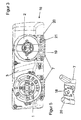
- Figur 2 einen Schnitt nach der Linie A - A in Figur 1,
- Figur 3 eine Rückansicht des Scheinwerfers mit einem Halter einer Lichtquelle für das Positionslicht,
- Figur 4 eine Rückansicht auf ein Abdeckelement des Scheinwerfers, das als Fixierelement für die Lichtleitringe und die Halter der Lichtquellen dient und
- Figur 5 in einer perspektivischen Ansicht den Halter mit Lichtquelle.
- Der Scheinwerfer für Fahrzeuge weist ein topfförmiges Gehäuse 14 und eine die vordere Öffnung des Gehäuses 14 verschließende Abschlussscheibe 15 auf. Im Inneren des Scheinwerfers ist eine Lichteinheit 16 angeordnet. Die Lichteinheit 16 ist um eine vertikale und horizontale Achse verstellbar (nicht dargestellt). Die Lichteinheit 16 besteht aus zwei Lichtelementen 1 und 2 und einem die Lichtelemente 1 und 2 tragenden Abdeckelement 3. Das Abdeckelement 3 deckt den Bereich zwischen den Lichtelementen 1 und 2 und dem vorderen Rand des Gehäuses 14 weitestgehend ab und ist auf seiner Vorderseite mit einer hochglänzenden silberfarbigen Beschichtung versehen. Das Lichtelement 1 besteht aus einem Projektionsmodul für Abblendlicht, dessen Linse von in einer Durchgangsöffnung des Abdeckelements 3 angeordnet ist, während das Lichtelement 2 ein schalenförmigen Reflektor ist der einstückig mit dem Abdeckelement 3 ausgeführt ist. Die Lichtelemente 1 und 2 sind jeweils von einem ringförmigen Lichtleitelement 4 umgeben, die auf der Vorderseite des Abdeckelements 3 angeordnet sind. An die Rückseite der Lichtleitelemente 4 sind jeweils drei Rastzungen 9 angeformt, die mit Rastnasen in Rastelemente 10 des Abdeckelements 3 selbsttätig eingreifen. Die Rastelemente 10 weisen Öffnungen in dem Abdeckelement 3 auf, durch die hindurch die in Aufsetzrichtung der Lichtleitelemente 4 weisende Rastzungen 9 führen. Bei jedem Lichtleitelement 4 verjüngt sich mindestens eine Rastzunge 9 mit schmalen Seitenflächen in Aufsetzrichtung und grenzt mit den schmalen Seitenflächen an ihrer Wurzel an den Rand der Öffnung des Rastelements 10 an. Das ringförmige Lichtleitelement 4 grenzt mit seiner Außenseite an eine kleine umlaufende Schulter 17 des Abdeckelements 3 an. Die Schulter 17 ist von einer Stufe in dem Abdeckelement 3 gebildet. Zwischen den Rastelementen 10 liegt das Lichtleitelement 4 an Erhebungen (nicht dargestellt) des Abdeckelements an. In dem unteren Bereich weisen die ringförmigen Lichtleitelemente 4 ein Lichteinkoppelelement mit einer Lichteinkoppelfläche 5 auf. Die Lichtei n-koppelfläche 5 ist einer Öffnung 8 des Abdeckelements 3 zugeordnet und weist zur Rückseite des Scheinwerfers. An der Rückseite des Abdeckelements 3 ist ein Halter 7 für eine Lichtquelle 6 befestigt. Die Lichtquelle 6 ist von einer Leuchtdiode gebildet, wobei der Halter 7 aus Metall besteht und im Druckgießverfahren hergestellt ist. Eine die Lichtquelle 6 tragende Leiterplatte 18 liegt flächig an dem Halter 7 an. Somit dient der metallische Halter 7 als Kühlkörper für die Lichtquelle 6. Der Halter 7 weist an seiner Rückseite mehrere Kühlrippen 19 auf. Die Längsachse 13 der Lichtquelle 6 verläuft ausgehende von dem Halter 7 schräg nach vorne und oben. Die Rückseite des Halters 7 verläuft etwa senkrecht zur Längsachse 13 der Lichtquelle 6. Somit benötigt der Halter 7 wenig Bauraum. Der Halter 7 weist an zwei sich abgewandten seitlichen Seiten jeweils eine nach vorne weisende Befestigungshülse 20 auf, die auf Befestigungsansätze 11 des Abdeckelements 3 aufgeschoben und durch Befestigungsschrauben an den Befestigungsansätzen 20 gehalten sind. Zusätzlich zu den beiden Befestigungsansätzen 20 ist an das Abdeckelement 3 zwischen den beiden Befestigungsansätzen 20 ein Fixierungsansatz 21 angeformt, der in entsprechende Öffnung des Halters 7, welche nahe seinem hinteren Rand angeordnet ist, eingeschoben ist. Zwischen der Öffnung für den Fixierungsansatz 21 und den Befestigungsansätzen 20 ist die Lichtquelle 6 angeordnet. Dadurch ist der Montage von den Lichtleitelementen 4 und dem Halter 7 die Lichtquelle 6 genau zu der Lichteinkoppelfläche 5 der Lichtleitelemente 4 ausgerichtet. Die zur Aufnahme der Lichteinkoppelfläche 5 und der Lichtquelle 6 dienende Öffnung 8 des Abdeckelements 3 ist durch eine Kappe 12 abgedeckt. Die Kappe 12 ist durch Laserschweißen an den Lichtleitelementen 4 befestigt, aus lichtundurchlässigem Material hergestellt und schirmt die im Bereich der Lichteinkoppelfläche 5 bestehenden störenden Lichtstrahlen ab. Die vordere Seite der Kappe 12 kann ein Emblem aufweisen. An der Rückseite weisen die ringförmigen Lichtleitelemente 4 umlaufend Reflexionselemente (nicht dargestellt) auf, die die Lichtstrahlen nach vorn reflektieren. Angrenzend an die Reflexionselemente sind an den äußeren rückwärtigen Rand der Lichtleitelemente 4 die Rastzungen 9 angeformt.
-
- 1.
- Lichtelement
- 2.
- Lichtelement
- 3.
- Abdeckelement
- 4.
- Lichtleitelement
- 5.
- Lichteinkoppelfläche
- 6.
- Lichtquelle
- 7.
- Halter
- 8.
- Öffnung
- 9.
- Rastzunge
- 10.
- Rastelement
- 11.
- Befestigungsansatz
- 12.
- Kappe
- 13.
- Längsachse
- 14.
- Gehäuse
- 15.
- Abschlussscheibe
- 16.
- Lichteinheit
- 17.
- Schulter
- 18.
- Leiterplatte
- 19.
- Kühlrippen
- 20.
- Befestigungshülse
- 21.
- Fixierungsansatz
Claims (12)
- Scheinwerfer für Fahrzeuge mit mindestens einem im Inneren des Scheinwerfers angeordneten Lichtelement (1, 2), mit einem Abdeckelement (3), das von der Vorderseite des Scheinwerfers her gesehen eine Lichtaustrittsöffnung des Lichtelements (1, 2) umgibt, mit einem ringförmigen Lichtleitelement (4), das an Vorderseite des Abdeckelements (3) angeordnet ist, zur Lichtaustrittsöffnung benachbart verläuft und eine Lichteinkoppelfläche (5) aufweist, und mit einer der Lichteinkoppelfläche (5) zugeordneten Lichtquelle (6),
dadurch gekennzeichnet, dass ein Halter (7) für die Lichtquelle (6) an der Rückseite des Abdeckelements (3) und/oder des Lichtelements (1 oder 2) angeordnet ist, die Lichtquelle (6) und die Lichteinkoppelfläche (5) des Lichtleitelements (4) einer Öffnung (8) des Abdeckelements (3) und/oder des Lichtelements (1 oder 2) zugeordnet sind und das Abdeckelement (3) und/oder das Lichtelement (1 oder 2) ein Fixierungselement für die Lichtquelle (6) und die der Lichtquelle (6) benachbarte Lichteinkoppelfläche (5) des Lichtleitelements (4) ist. - Scheinwerfer nach Anspruch 1, dadurch gekennzeichnet, dass an die Rückseite des ringförmigen Lichtleitelements (4) mehrere Rastzungen (9) angeformt sind, die in Rastelemente (10) des Abdeckelements (3) und/oder des Lichtelements (1 oder 2) eingreifen und das Lichtleitelement (4) in Aufsetzrichtung und in Umfangsrichtung an dem Abdeckelement (3) und/oder dem Lichtelement (1 oder 2) fixieren.
- Scheinwerfer nach Anspruch 2, dadurch gekennzeichnet, dass mindestens eine Rastzunge (9) sich in Einsetzrichtung verjüngt und mit den die Verjüngung bildenden Seiten das ringförmige Lichtleitelement (4) in seiner Umfangsrichtung fixiert.
- Scheinwerfer nach einem der Ansprüche 1 bis 3, dadurch gekennzeichnet, dass das ringförmige Lichtleitelement (4) mit seiner Außenseite an eine Schulter (17) des Abdeckelements (3) und/oder des Lichtelements (1 oder 2) angrenzt.
- Scheinwerfer nach einem der Ansprüche, 1 bis 4, dadurch gekennzeichnet, dass an die Rückseite des Abdeckelements (3) und/oder des Lichtelements (1 oder 2) mehrere Befestigungsansätze (11) zur Fixierung des Halters an dem Abdeckelement (3) und/oder dem Lichtelement (1 oder 2) anformt sind.
- Scheinwerfer nach einem der Ansprüche 1 bis 5, dadurch gekennzeichnet, dass die für die Lichteinkoppelfläche (5) und die Lichtquelle (6) zugeordnete Öffnung (8) des Abdeckelements (3) und/oder des Lichtelements (1 oder 2) im unteren Bereich des ringförmigen Lichtleitelements (4) angeordnet ist und von der Vorderseite des Scheinwerfers her gesehen von einer Kappe (12) abgedeckt ist.
- Scheinwerfer nach Anspruch 6, dass die Kappe (12) an dem Lichtleitelement (4) befestigt ist.
- Scheinwerfer nach Anspruch 7, dadurch gekennzeichnet, das die Kappe (12) durch Laserschweißstellen an dem Lichtleitelement (4) gehalten ist.
- Scheinwerfer nach einem der Ansprüche 1 bis 8, dadurch gekennzeichnet, dass die Lichtquelle (6) eine Leuchtdiode und der Halter (7) ein Kühlkörper für die Leuchtdiode ist.
- Scheinwerfer nach Anspruch 9, dadurch gekennzeichnet, dass die Längsachse (13) der Lichtquelle (6) ausgehend von dem Halter (7) schräg nach vorn und oben verläuft.
- Scheinwerfer nach einem der Ansprüche 1 bis 10, dadurch gekenn-zeichnet, dass das Lichtleitelement (4) mit seiner Rückseite unter Vorspannung an zwischen den Rastelementen (10) angeordneten Erhebungen des Abdeckelements (3) anliegt.
- Scheinwerfer nach einem der Ansprüche 1 bis 11, dadurch gekenn-zeichnet, dass die Rastzungen (9) am äußeren oder inneren rückwärtigen Randbereich der Lichtleitelemente (4) und außerhalb von einem optischen Reflexionsbereich des Lichtleitelements (4) angeformt sind.
Applications Claiming Priority (2)
| Application Number | Priority Date | Filing Date | Title |
|---|---|---|---|
| DE10251812A DE10251812A1 (de) | 2002-11-07 | 2002-11-07 | Scheinwerfer für Fahrzeuge |
| DE10251812 | 2002-11-07 |
Publications (3)
| Publication Number | Publication Date |
|---|---|
| EP1418087A2 EP1418087A2 (de) | 2004-05-12 |
| EP1418087A3 EP1418087A3 (de) | 2005-04-20 |
| EP1418087B1 true EP1418087B1 (de) | 2006-09-06 |
Family
ID=32103393
Family Applications (1)
| Application Number | Title | Priority Date | Filing Date |
|---|---|---|---|
| EP03103868A Expired - Fee Related EP1418087B1 (de) | 2002-11-07 | 2003-10-20 | Scheinwerfer für Fahrzeuge |
Country Status (3)
| Country | Link |
|---|---|
| EP (1) | EP1418087B1 (de) |
| DE (2) | DE10251812A1 (de) |
| ES (1) | ES2272892T3 (de) |
Families Citing this family (7)
| Publication number | Priority date | Publication date | Assignee | Title |
|---|---|---|---|---|
| JP4606930B2 (ja) * | 2005-04-18 | 2011-01-05 | 本田技研工業株式会社 | 車両用灯火装置 |
| DE102006027970A1 (de) * | 2005-10-19 | 2007-10-04 | Volkswagen Ag | Scheinwerfereinheit für ein Fahrzeug mit einem Tagfahrlicht |
| DE102006059902B4 (de) * | 2006-12-19 | 2019-05-09 | HELLA GmbH & Co. KGaA | Scheinwerfer für Fahrzeuge |
| US8333493B2 (en) | 2009-04-03 | 2012-12-18 | North American Lighting, Inc. | Dual-direction light pipe for automotive lighting |
| ITTV20110034A1 (it) * | 2011-03-04 | 2012-09-05 | Automotive Lighting Italia Spa | Fanale automobilistico |
| DE102013009178A1 (de) | 2013-05-31 | 2014-12-04 | Volkswagen Aktiengesellschaft | Leuchtvorrichtung für ein Kraftfahrzeug mit einem schwenkbaren Tragrahmen sowie ein Kraftfahrzeug |
| AT514405B1 (de) | 2013-06-07 | 2015-05-15 | Zkw Slovakia S R O | Beleuchtungskörper für ein Fahrzeug |
Family Cites Families (8)
| Publication number | Priority date | Publication date | Assignee | Title |
|---|---|---|---|---|
| US6168302B1 (en) * | 1997-12-09 | 2001-01-02 | Cooper Automotive Products, Inc. | Hybrid distributed lighting system for a vehicle |
| DE19943821A1 (de) * | 1999-09-14 | 2001-03-15 | Valeo Beleuchtung Deutschland | Leuchte, insbesondere für Kraftfahrzeuge |
| DE10028282A1 (de) * | 1999-12-08 | 2001-06-13 | Hella Kg Hueck & Co Patente Ma | Scheinwerfereinheit für Fahrzeuge |
| DE10040302B4 (de) * | 2000-08-17 | 2007-04-05 | Hella Kgaa Hueck & Co. | Signalleuchte eines Fahrzeugs |
| DE10114123A1 (de) * | 2001-03-22 | 2002-09-26 | Hella Kg Hueck & Co | Scheinwerfer für Fahrzeuge |
| DE10127966A1 (de) * | 2001-06-08 | 2002-12-12 | Hella Kg Hueck & Co | Scheinwerfer für Fahrzeuge |
| US6471368B1 (en) * | 2001-09-26 | 2002-10-29 | Yu-Chu Lin | Secondary alert light for motor vehicles |
| DE20214177U1 (de) * | 2002-09-11 | 2003-02-27 | Dj Auto Components Corp | Leuchtenstruktur |
-
2002
- 2002-11-07 DE DE10251812A patent/DE10251812A1/de not_active Withdrawn
-
2003
- 2003-10-20 DE DE50304935T patent/DE50304935D1/de not_active Expired - Lifetime
- 2003-10-20 ES ES03103868T patent/ES2272892T3/es not_active Expired - Lifetime
- 2003-10-20 EP EP03103868A patent/EP1418087B1/de not_active Expired - Fee Related
Also Published As
| Publication number | Publication date |
|---|---|
| DE10251812A1 (de) | 2004-05-19 |
| EP1418087A3 (de) | 2005-04-20 |
| EP1418087A2 (de) | 2004-05-12 |
| ES2272892T3 (es) | 2007-05-01 |
| DE50304935D1 (de) | 2006-10-19 |
Similar Documents
| Publication | Publication Date | Title |
|---|---|---|
| DE19652159B4 (de) | Beleuchtungseinrichtung für Fahrzeuge | |
| DE19621254B4 (de) | Fahrzeugscheinwerfer | |
| DE19814480B4 (de) | Scheinwerfer für Fahrzeuge nach dem Projektionsprinzip | |
| DE102016109132A1 (de) | Scheinwerfer, insbesondere Scheinwerfer eines Kraftfahrzeugs | |
| EP1243467B1 (de) | Scheinwerfer für Fahrzeuge | |
| DE19704426A1 (de) | Scheinwerfer für Fahrzeuge nach dem Projektionsprinzip | |
| DE19519872A1 (de) | Scheinwerfer für Fahrzeuge | |
| DE10040302B4 (de) | Signalleuchte eines Fahrzeugs | |
| DE10109357B4 (de) | Beleuchtungseinrichtung eines Fahrzeugs | |
| EP1418087B1 (de) | Scheinwerfer für Fahrzeuge | |
| DE102005050420B4 (de) | Kraftfahrzeugscheinwerfer | |
| DE10115868B4 (de) | Scheinwerfereinheit eines Kraftfahrzeugs | |
| DE102011053032A1 (de) | Leuchteneinheit für Fahrzeuge | |
| DE19839194A1 (de) | Scheinwerfer für Fahrzeuge nach dem Projektionsprinzip | |
| DE10314256A1 (de) | Leuchte für Fahrzeuge | |
| DE19507585A1 (de) | Scheinwerfer-Leuchten-Einheit für Fahrzeuge | |
| DE102004003402A1 (de) | Fahrzeugscheinwerfer | |
| DE102008012195A1 (de) | Beleuchtungsvorrichtung für Kraftfahrzeuge | |
| DE10308704A1 (de) | Kraftfahrzeugscheinwerfer | |
| EP0985871A2 (de) | Scheinwerfer und Verfahren zum Herstellen eines Scheinwerfers | |
| EP0422084A1 (de) | Leuchte, insbesondere für kraftfahrzeuge. | |
| EP1052449B1 (de) | Scheinwerfer für Fahrzeuge | |
| DE19734090B4 (de) | Leuchte für Fahrzeuge mit einem Abschirmteil und mit einer Rastvorrichtung | |
| EP0935727B1 (de) | Scheinwerfer für fahrzeuge | |
| DE19535704A1 (de) | Scheinwerfer für Fahrzeuge |
Legal Events
| Date | Code | Title | Description |
|---|---|---|---|
| PUAI | Public reference made under article 153(3) epc to a published international application that has entered the european phase |
Free format text: ORIGINAL CODE: 0009012 |
|
| AK | Designated contracting states |
Kind code of ref document: A2 Designated state(s): AT BE BG CH CY CZ DE DK EE ES FI FR GB GR HU IE IT LI LU MC NL PT RO SE SI SK TR |
|
| AX | Request for extension of the european patent |
Extension state: AL LT LV MK |
|
| RAP1 | Party data changed (applicant data changed or rights of an application transferred) |
Owner name: HELLA KGAA HUECK & CO. |
|
| PUAL | Search report despatched |
Free format text: ORIGINAL CODE: 0009013 |
|
| AK | Designated contracting states |
Kind code of ref document: A3 Designated state(s): AT BE BG CH CY CZ DE DK EE ES FI FR GB GR HU IE IT LI LU MC NL PT RO SE SI SK TR |
|
| AX | Request for extension of the european patent |
Extension state: AL LT LV MK |
|
| 17P | Request for examination filed |
Effective date: 20051019 |
|
| GRAP | Despatch of communication of intention to grant a patent |
Free format text: ORIGINAL CODE: EPIDOSNIGR1 |
|
| AKX | Designation fees paid |
Designated state(s): DE ES FR GB IT SE |
|
| RAP1 | Party data changed (applicant data changed or rights of an application transferred) |
Owner name: HELLA KG HUECK & CO. |
|
| RIN1 | Information on inventor provided before grant (corrected) |
Inventor name: HACK, MICHAEL Inventor name: HAASE, CHRISTIAN Inventor name: GORCZYCA, CHRISTIAN |
|
| RAP1 | Party data changed (applicant data changed or rights of an application transferred) |
Owner name: HELLA KGAA HUECK & CO. |
|
| RIN1 | Information on inventor provided before grant (corrected) |
Inventor name: HACK, MICHAEL Inventor name: GORCZYCA, CHRISTIAN Inventor name: HAASE, CHRISTIAN |
|
| GRAS | Grant fee paid |
Free format text: ORIGINAL CODE: EPIDOSNIGR3 |
|
| GRAA | (expected) grant |
Free format text: ORIGINAL CODE: 0009210 |
|
| AK | Designated contracting states |
Kind code of ref document: B1 Designated state(s): DE ES FR GB IT SE |
|
| PG25 | Lapsed in a contracting state [announced via postgrant information from national office to epo] |
Ref country code: IT Free format text: LAPSE BECAUSE OF FAILURE TO SUBMIT A TRANSLATION OF THE DESCRIPTION OR TO PAY THE FEE WITHIN THE PRESCRIBED TIME-LIMIT;WARNING: LAPSES OF ITALIAN PATENTS WITH EFFECTIVE DATE BEFORE 2007 MAY HAVE OCCURRED AT ANY TIME BEFORE 2007. THE CORRECT EFFECTIVE DATE MAY BE DIFFERENT FROM THE ONE RECORDED. Effective date: 20060906 |
|
| REG | Reference to a national code |
Ref country code: GB Ref legal event code: FG4D Free format text: NOT ENGLISH |
|
| REG | Reference to a national code |
Ref country code: SE Ref legal event code: TRGR |
|
| GBT | Gb: translation of ep patent filed (gb section 77(6)(a)/1977) |
Effective date: 20060923 |
|
| REF | Corresponds to: |
Ref document number: 50304935 Country of ref document: DE Date of ref document: 20061019 Kind code of ref document: P |
|
| ET | Fr: translation filed | ||
| REG | Reference to a national code |
Ref country code: ES Ref legal event code: FG2A Ref document number: 2272892 Country of ref document: ES Kind code of ref document: T3 |
|
| PLBE | No opposition filed within time limit |
Free format text: ORIGINAL CODE: 0009261 |
|
| STAA | Information on the status of an ep patent application or granted ep patent |
Free format text: STATUS: NO OPPOSITION FILED WITHIN TIME LIMIT |
|
| 26N | No opposition filed |
Effective date: 20070607 |
|
| PGFP | Annual fee paid to national office [announced via postgrant information from national office to epo] |
Ref country code: ES Payment date: 20081121 Year of fee payment: 6 |
|
| PGFP | Annual fee paid to national office [announced via postgrant information from national office to epo] |
Ref country code: IT Payment date: 20081025 Year of fee payment: 6 Ref country code: SE Payment date: 20081022 Year of fee payment: 6 |
|
| PGFP | Annual fee paid to national office [announced via postgrant information from national office to epo] |
Ref country code: FR Payment date: 20081014 Year of fee payment: 6 |
|
| PGFP | Annual fee paid to national office [announced via postgrant information from national office to epo] |
Ref country code: GB Payment date: 20081015 Year of fee payment: 6 |
|
| EUG | Se: european patent has lapsed | ||
| REG | Reference to a national code |
Ref country code: FR Ref legal event code: ST Effective date: 20100630 |
|
| PG25 | Lapsed in a contracting state [announced via postgrant information from national office to epo] |
Ref country code: FR Free format text: LAPSE BECAUSE OF NON-PAYMENT OF DUE FEES Effective date: 20091102 |
|
| PG25 | Lapsed in a contracting state [announced via postgrant information from national office to epo] |
Ref country code: GB Free format text: LAPSE BECAUSE OF NON-PAYMENT OF DUE FEES Effective date: 20091020 |
|
| REG | Reference to a national code |
Ref country code: ES Ref legal event code: FD2A Effective date: 20110310 |
|
| PG25 | Lapsed in a contracting state [announced via postgrant information from national office to epo] |
Ref country code: IT Free format text: LAPSE BECAUSE OF NON-PAYMENT OF DUE FEES Effective date: 20091020 |
|
| PG25 | Lapsed in a contracting state [announced via postgrant information from national office to epo] |
Ref country code: SE Free format text: LAPSE BECAUSE OF NON-PAYMENT OF DUE FEES Effective date: 20091021 |
|
| PG25 | Lapsed in a contracting state [announced via postgrant information from national office to epo] |
Ref country code: ES Free format text: LAPSE BECAUSE OF NON-PAYMENT OF DUE FEES Effective date: 20110309 |
|
| PG25 | Lapsed in a contracting state [announced via postgrant information from national office to epo] |
Ref country code: ES Free format text: LAPSE BECAUSE OF NON-PAYMENT OF DUE FEES Effective date: 20091021 |
|
| PGFP | Annual fee paid to national office [announced via postgrant information from national office to epo] |
Ref country code: DE Payment date: 20141014 Year of fee payment: 12 |
|
| REG | Reference to a national code |
Ref country code: DE Ref legal event code: R119 Ref document number: 50304935 Country of ref document: DE |
|
| PG25 | Lapsed in a contracting state [announced via postgrant information from national office to epo] |
Ref country code: DE Free format text: LAPSE BECAUSE OF NON-PAYMENT OF DUE FEES Effective date: 20160503 |