EP1416298A2 - Endstück für eine Unterwasser-Schleppantenne - Google Patents
Endstück für eine Unterwasser-Schleppantenne Download PDFInfo
- Publication number
- EP1416298A2 EP1416298A2 EP03024493A EP03024493A EP1416298A2 EP 1416298 A2 EP1416298 A2 EP 1416298A2 EP 03024493 A EP03024493 A EP 03024493A EP 03024493 A EP03024493 A EP 03024493A EP 1416298 A2 EP1416298 A2 EP 1416298A2
- Authority
- EP
- European Patent Office
- Prior art keywords
- funnel
- end piece
- piece according
- towing
- antenna
- Prior art date
- Legal status (The legal status is an assumption and is not a legal conclusion. Google has not performed a legal analysis and makes no representation as to the accuracy of the status listed.)
- Granted
Links
Images

Classifications
-
- G—PHYSICS
- G01—MEASURING; TESTING
- G01V—GEOPHYSICS; GRAVITATIONAL MEASUREMENTS; DETECTING MASSES OR OBJECTS; TAGS
- G01V1/00—Seismology; Seismic or acoustic prospecting or detecting
- G01V1/38—Seismology; Seismic or acoustic prospecting or detecting specially adapted for water-covered areas
- G01V1/3817—Positioning of seismic devices
-
- B—PERFORMING OPERATIONS; TRANSPORTING
- B63—SHIPS OR OTHER WATERBORNE VESSELS; RELATED EQUIPMENT
- B63B—SHIPS OR OTHER WATERBORNE VESSELS; EQUIPMENT FOR SHIPPING
- B63B21/00—Tying-up; Shifting, towing, or pushing equipment; Anchoring
- B63B21/56—Towing or pushing equipment
- B63B21/66—Equipment specially adapted for towing underwater objects or vessels, e.g. fairings for tow-cables
-
- G—PHYSICS
- G01—MEASURING; TESTING
- G01V—GEOPHYSICS; GRAVITATIONAL MEASUREMENTS; DETECTING MASSES OR OBJECTS; TAGS
- G01V1/00—Seismology; Seismic or acoustic prospecting or detecting
- G01V1/38—Seismology; Seismic or acoustic prospecting or detecting specially adapted for water-covered areas
- G01V1/3843—Deployment of seismic devices, e.g. of streamers
-
- G—PHYSICS
- G01—MEASURING; TESTING
- G01V—GEOPHYSICS; GRAVITATIONAL MEASUREMENTS; DETECTING MASSES OR OBJECTS; TAGS
- G01V5/00—Prospecting or detecting by the use of ionising radiation, e.g. of natural or induced radioactivity
-
- G—PHYSICS
- G01—MEASURING; TESTING
- G01V—GEOPHYSICS; GRAVITATIONAL MEASUREMENTS; DETECTING MASSES OR OBJECTS; TAGS
- G01V5/00—Prospecting or detecting by the use of ionising radiation, e.g. of natural or induced radioactivity
- G01V5/02—Prospecting or detecting by the use of ionising radiation, e.g. of natural or induced radioactivity specially adapted for surface logging, e.g. from aircraft
-
- G—PHYSICS
- G01—MEASURING; TESTING
- G01V—GEOPHYSICS; GRAVITATIONAL MEASUREMENTS; DETECTING MASSES OR OBJECTS; TAGS
- G01V5/00—Prospecting or detecting by the use of ionising radiation, e.g. of natural or induced radioactivity
- G01V5/02—Prospecting or detecting by the use of ionising radiation, e.g. of natural or induced radioactivity specially adapted for surface logging, e.g. from aircraft
- G01V5/025—Prospecting or detecting by the use of ionising radiation, e.g. of natural or induced radioactivity specially adapted for surface logging, e.g. from aircraft specially adapted for use from aircraft
-
- G—PHYSICS
- G01—MEASURING; TESTING
- G01V—GEOPHYSICS; GRAVITATIONAL MEASUREMENTS; DETECTING MASSES OR OBJECTS; TAGS
- G01V5/00—Prospecting or detecting by the use of ionising radiation, e.g. of natural or induced radioactivity
- G01V5/20—Detecting prohibited goods, e.g. weapons, explosives, hazardous substances, contraband or smuggled objects
-
- B—PERFORMING OPERATIONS; TRANSPORTING
- B63—SHIPS OR OTHER WATERBORNE VESSELS; RELATED EQUIPMENT
- B63B—SHIPS OR OTHER WATERBORNE VESSELS; EQUIPMENT FOR SHIPPING
- B63B21/00—Tying-up; Shifting, towing, or pushing equipment; Anchoring
- B63B21/24—Anchors
- B63B21/48—Sea-anchors; Drogues
Definitions
- the invention relates to an end piece for a towable Underwater towing antenna to generate one of the Tow direction opposite tensile force on Trailing antenna end.
- Underwater towing antennas e.g. from the GB 21 49 916 A are known to consist of one Trailing cable, a tubular trailing strand, which the acoustic section of the trailing antenna, and one End piece, a so-called rope tail or rope drogue, together, that has the task of creating one of the Tow direction opposite tensile force, the Tow strand largely stretched during towing to keep.
- the pull cable is attached to the tow line and the end piece is free at the end.
- Trailing cable and the trailing strand on the one hand and the Towline and the tail on the other hand are in general vibration damping modules, so-called VIM's, for acoustic decoupling of the tow from the pull cable and End piece arranged.
- VIM's vibration damping modules
- a known end piece of this type exists from a plurality of nylon threads with a length of approx. 30m and a thread diameter of approx. 15mm, of which the one end by means of a rotating coupling on the rear VIM attached and the other end is free.
- Such one Tail can be for a fixed set Towing speed can be designed so that it is due its flow resistance in water one for stretching the acoustically sensitive part of the towing antenna sufficient traction at the trailing antenna end.
- the invention has for its object an end piece for to create an underwater towing antenna that also at low drag speeds of the water flow opposed sufficiently high flow resistance and thus a sufficiently high one to stretch the towline Tractive force at the end of the towing antenna generates that with increasing higher towing speed increases only moderately.
- the end piece according to the invention for an underwater towing antenna has the advantage that the molded body through their Shape design and number even at low Towing speed for a sufficiently high Flow resistance of the end piece and thus for one sufficient traction to extend the trailing antenna to care.
- This tractive force increases up to a predetermined one Drag speed because of the flow resistance grows square with the towing speed.
- the inventive dimensioning of the distances between the Shaped bodies are above the specified Drag speed the fittings in the flow shadow or so-called dead water in the direction of towing previous shaped body, so that the regularity of the quadratic increase in flow resistance with the Towing speed is canceled and the most Tractive antenna end generated traction much less with the towing speed increases.
- the end piece can be advantageously as a pull-out aid for generating one at the end of spreading Towing antenna attacking traction when the Use a trailing antenna if the moldings are in one Flushing pipe with an inlet and outlet opening for the tubular trailing antenna are slidably guided by and a water pressure in the flushing pipe from the inlet opening is built up.
- the moldings act in this Use case like pistons that are affected by the water pressure through the Rinsing tube are pushed through and on the Tow antenna end attached rope a traction on the Apply a tubular tow.
- the moldings are made of Teflon, so they are high Slidability with low frictional resistance in the flushing pipe exhibit.
- the distances between those set on the rope Shaped bodies within the flow shadow area set differently.
- the moldings are rotatably arranged around the rope.
- each molded body has a funnel in the towing direction pointing funnel opening, as well as one at the of the Funnel opening opposite end arranged over the Funnel jacket protruding end plate.
- the Funnel design of the fitting with the one behind it End plate ensures in the free flow at low Towing speed for a sufficiently high Flow resistance and thus for a to stretch the Towing rope sufficiently high traction with not too large Number of shaped bodies on the rope, so that an acceptable Length of the end piece can be realized.
- the outer diameter of the end plate is equal to that Outside diameter of the funnel at the funnel opening dimensioned and the funnel jacket with in the circumferential direction Axial webs offset from each other, which differ from extend the funnel opening to the end plate and its outer web lines running parallel to the funnel axis a radial corresponding to the outer radius of the end plate Distance from the funnel axis.
- On the funnel opening is one with axial openings Final cone placed, and in the final cone, on The bottom of the funnel and in the end plate is a central one Through hole arranged for the rope, the Hole diameter is larger than the outside diameter of the Rope.
- the cone shape of the final cone, the radii on the Outer edges and the axial webs ensure that the Use of the end piece as a pull-out aid to secure the Towing antenna the fittings in the flushing pipe Center the spreading device for the trailing antenna yourself and do not get caught in the flushing pipe.
- the length of the fittings is tilted in the flushing pipe locked out.
- the final cone also provides sure that when repeating the trailing antenna the Fittings easily through the outlet of the Flush pipe can be pulled through and a safe "Threading" the end piece into the flushing pipe is guaranteed.
- the last shaped body in the towing direction a stop in Form of a preferably frustoconical closure member on that for closing the outlet opening of the flushing pipe is trained.
- This closure member can with the End plate are made in one piece. After threading of the end piece in the flushing pipe when repeating the Tow antenna attaches the locking member to the Outlet opening of the flushing pipe and prevents another Retraction of the end piece and penetration of foreign bodies into the flushing pipe. At the same time, this can mark the end of Repetition sensed and the catch winch for the Tow antenna can be switched off.
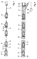
- the end piece shown in detail in FIG. 1 for a towable underwater towing antenna for generating a tractive force opposite to the towing direction at the towing antenna end has a cable 11 on which a large number of shaped bodies 12, which are designed to generate a flow resistance, are arranged.
- the molded bodies 12 are axially spaced apart from one another essentially fixed on the rope 11, but can rotate on the rope 11.
- the distances d of the shaped bodies 12 from one another are selected such that when a predetermined drag speed is exceeded, each shaped body 12 downstream of a shaped body 12 lies in the area of the flow shadow or "dead water" generated by the preceding shaped body 12.
- the distances d between the molded bodies 12 are defined differently within this distance dimensioning, which is fixed to the flow shadow area, as a comparison of the two distances d 1 and d 2 shown in FIG. 1 shows.
- the different distances d are arbitrary and random.
- the rope 11 is attached to a hose member 10 which in turn with the end of the acoustically sensitive part of the tow antenna forming tubular tow strand is connectable, preferably between the end of Dragline and the hose member 10 still one Towline acoustically decoupling from the tail Damping module, a so-called VIM, is arranged.
- the Hose member 10 has an elastic, by means of fittings stiffened hose cover with a liquid, e.g. Oil, or a gel is filled.
- All shaped bodies 12 are of identical design and consist from two parts, a funnel part 13 and one with the Funnel part 13 connected end cone 14.
- Funnel part 13 and end cone 14 are made of Teflon.
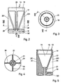
- in the Funnel part 13 is a funnel 15 with in the towing direction pointing funnel opening 16 and one at that of the Funnel opening 16 is arranged opposite end, over the Outer contours of the funnel jacket 17 protruding end plate 18 trained.
- the end plate 18 is rounded on the outside.
- the Curvatures of the outer shell of the end plate 18 to both Disc surfaces are in Fig. 1, 5 and 6 with 181st characterized.
- the funnel opening 16 is a cylindrical one Ring edge 19 upstream, the inner diameter of the Funnel opening 16 and its outer diameter Outer diameter of the end plate 18 corresponds.
- On the Funnel jacket 17 are four in the circumferential direction by 90 ° Axial webs 20 offset with respect to one another (FIG. 4) put on, which is from the funnel opening 16, ie from the Trailing edge of the ring edge 19 to the Funnel opening 16 facing front edge of the end plate 18, extend (Fig. 2, 5 and 6).
- the outer bridge line 201 of the Axial webs 20 run parallel to the funnel axis or Axis of the funnel part 13 and has a radial distance from the funnel axis, which is equal to the outer radius of the End plate 18 is.
- In the end plate 18 is a central one Through hole 21 introduced, which extends to Funnel base of the funnel 15 extends and in the funnel 15 flows freely.
- the bore diameter is chosen larger than the outer diameter of the rope 11.
- the closing cone 14 which can be placed on the funnel opening 16 has three axial angles offset by 120 ° Through openings 22 and a central through hole 23 on, whose bore diameter is chosen larger than that Outside diameter of the rope 11.
- the passage openings 22 are made so big that practically only bridges between they remain, which are arranged in a star shape. in the The through point runs through the star point 23.
- the Outer diameter of the base of the end cone 14, the funnel opening 16 is facing is equal to that Outer diameter of the ring rim 19 on the funnel part 13 dimensioned so that the end cone 14 and funnel part 13th are seamlessly assembled.
- an axial protruding ring web 24 formed, the form-fitting in the cylindrical ring edge 19 of the funnel part 13 axially can be inserted.
- funnel part 13 and End cone 14 firmly connected, e.g. by several screw connections between ring edge 19 and ring web 24.
- the axial immovability of the molded body 12 on the Rope 11 is e.g. by rope knots, not shown here causes, which are preferably inside the funnel 15, so that the bottom of the funnel and the Base of the end cone 14 on a rope knot support.
- the described end piece with the large number of shaped bodies 12 serves not only to stretch the acoustic part of the Tow antenna forming towline, but will at the same time as a pull-out aid for generating an am
- the inside diameter of the Flushing pipe 25 is dimensioned slightly larger than that Outside diameter of the shaped body 12, that is, the outside diameter of end plate 18, axial webs 20, ring rim 19 and base of the end cone 14.
- the flushing pipe 25 has an inlet opening 251 and an outlet opening 252 for the hose member 10 and the attached tubular trailing antenna.
- a water inlet 28 is arranged on a Water pump 29 is connected.
- a frustoconical closure member 26 On the last shaped body 12 of the end piece in the towing direction a frustoconical closure member 26 is arranged, the serves as a stop and to close the outlet opening 252 of the flushing pipe 25 is formed.
- the closure member 26 is on the rope 11 or on the last shaped body 12 on whose end plate 18, attached, but can also with the End plate 18 of the last molded body 12 in one piece be carried out.
- the winding drum is used to deploy the trailing antenna driven in the axial direction, is previously by means of Water pump 29 near the inlet opening 251 a water pressure from e.g. 2 to 3 bar built up in the flushing pipe 25. Since the The outer diameter of the molded body 12 is only slightly smaller is act as the clear diameter of the flushing tube 25 Shaped body 12 as a piston, so that a by the 'water pressure tensile force on the cable 11 directed towards the outlet opening 252 is generated, the trailing antenna through the purge pipe 25th pulls outwards to exit into the water.
- the Conical shape of the end cone 14 and the axial webs 20 on Funnel part 13 ensure that the fittings 12 themselves center yourself and not on tolerance-related paragraphs in the Rinsing pipe 25 get caught.
Landscapes
- Physics & Mathematics (AREA)
- Life Sciences & Earth Sciences (AREA)
- General Life Sciences & Earth Sciences (AREA)
- Geophysics (AREA)
- General Physics & Mathematics (AREA)
- Engineering & Computer Science (AREA)
- High Energy & Nuclear Physics (AREA)
- Acoustics & Sound (AREA)
- Remote Sensing (AREA)
- Geology (AREA)
- Environmental & Geological Engineering (AREA)
- Oceanography (AREA)
- Aviation & Aerospace Engineering (AREA)
- Chemical & Material Sciences (AREA)
- Combustion & Propulsion (AREA)
- Mechanical Engineering (AREA)
- Ocean & Marine Engineering (AREA)
- Details Of Aerials (AREA)
Abstract
Description
- Fig. 1
- ausschnittweise eine Seitenansicht eines Endstücks für eine Unterwasser-Schleppantenne,
- Fig. 2
- eine Seitenansicht des Trichterteils eines sich aus Trichterteil und Abschlußkegel zusammensetzenden Formkörpers im Endstück gemäß Fig. 1,
- Fig. 3
- eine Unteransicht des Trichterteils in Richtung Pfeil III in Fig. 2,
- Fig. 4
- einen Schnitt längs der Linie IV - IV in Fig. 2,
- Fig. 5
- einen Schnitt längs der Linie V - V in Fig. 3,
- Fig. 6
- eine perspektivische Darstellung des Trichterteils,
- Fig. 7
- eine Draufsicht eines Abschlußkegels des Formkörpers im Endstück gemäß Fig. 1,
- Fig. 8
- einen Schnitt längs der Linie VIII - VIII in Fig. 7,
- Fig. 9
- ausschnittweise einen Längsschnitt eines Spülrohrs einer Ausbringvorrichtung für die Schleppantenne mit darin eingezogenem Endstück gemäß Fig. 1.
Claims (16)
- Endstück für eine nachschleppbare Unterwasser-Schleppantenne zur Erzeugung einer der Schlepprichtung entgegengerichteten Zugkraft am Schleppantennenende, gekennzeichnet durch eine Vielzahl von auf einem Seil (11) im Abstand voneinander, axial im wesentlichen unverschieblich angeordneten Formkörpern (12), die zur Erzeugung eines Strömungswiderstandes ausgebildet sind, und dadurch, daß die Abstände (d) der Formkörper (12) so bemessen sind, daß bei Übersteigen einer festgelegten Schleppgeschwindigkeit jeder einem Formkörper (12) in Schlepprichtung nachgeordnete Formkörper (12) im Bereich des vom vorausliegenden Formkörper (12) erzeugten Strömungsschattens liegt.
- Endstück nach Anspruch 1, dadurch gekennzeichnet, daß die Abstände (d) der Formkörper (12) innerhalb des Strömungsschattenbereichs willkürlich unterschiedlich bemessen sind.
- Endstück nach Anspruch 1 oder 2, dadurch gekennzeichnet, daß die Formkörper (12) um das Seil (11) drehbar angeordnet sind.
- Endstück nach einem der Ansprüche 1 - 3, dadurch gekennzeichnet, daß jeder Formkörper (12) einen Trichter (15) mit in Schlepprichtung weisender Trichteröffnung (16), sowie eine an dem von der Trichteröffnung (16) abgekehrten Ende angeordnete, über den Trichtermantel (17) radial vorstehende Endscheibe (18) aufweist.
- Endstück nach Anspruch 4, dadurch gekennzeichnet, daß der Mantel der Endscheibe (18) zu beiden Scheibenflächen hin abgerundet ist.
- Endstück nach Anspruch 4 oder 5, dadurch gekennzeichnet, daß der Außendurchmesser der Endscheibe (18) gleich dem Außendurchmesser des Trichters (15) an der Trichteröffnung (16) ist.
- Endstück nach einem der Ansprüche 4 - 6, dadurch gekennzeichnet, daß auf dem Trichtermantel (17) in Umfangsrichtung gegeneinander versetzte Axialstege (20) aufgesetzt sind, die sich von der Trichteröffnung (16) bis zur Endscheibe (18) erstrecken und deren parallel zur Trichterachse verlaufende, äußere Steglinien (201) einen den Außenradius der Endscheibe (18) entsprechenden Radialabstand von der Trichterachse haben.
- Endstück nach Anspruch 7, dadurch gekennzeichnet, daß der Drehwinkelversatz der Axialstege 90° beträgt.
- Endstück nach einem der Ansprüche 4 - 8, dadurch gekennzeichnet, daß auf die Trichteröffnung (16) ein axiale Druchtrittsöffnungen (22) aufweisender Abschlußkegel (14) aufgesetzt ist und daß im Abschlußkegel (14), im Trichtergrund und in der Endscheibe (18) jeweils eine zentrale Durchgangsbohrung (23, 21) vorgesehen ist, deren Bohrungsdruchmesser größer ist als der Außendurchmesser des Seils (11).
- Endstück nach Anspruch 9, dadurch gekennzeichnet, daß der Trichteröffnung (16) ein Ringrand (19) mit einem den Durchmesser der Trichteröffnung (16) entsprechenden Innendurchmesser vorgeordnet ist und daß an dem trichterseitigen Ende des Abschlußkegels (14) ein Ringsteg (24) axial vorsteht, der formschlüssig in den Ringrand (19) einschiebbar ist.
- Endstück nach Anspruch 10, dadurch gekennzeichnet, daß der Durchmesser der Grundfläche des Abschlußkegels (14) gleich dem Außendurchmesser des Ringrands (19) bemessen ist.
- Endstück nach einem der Ansprüche 1 - 11, gekennzeichnet durch seine Verwendung als Auszugshilfe zur Erzeugung einer am Ausbringende der Schleppantenne angreifenden Zugkraft beim Fieren der Schleppantenne, indem die Formkörper (12) in einem Spülrohr (25) mit einer einund Austrittsöffnung (251, 252) für die schlauchförmige Schleppantenne gleitend geführt sind und von der Eintrittsöffnung (251) des Spülrohrs (25) her ein Wasserdruck im Spülrohr (25) aufgebaut wird.
- Endstück nach Anspruch 12, dadurch gekennzeichnet, daß die Formkörper (12) aus gut gleitfähigem Material, vorzugsweise Teflon, bestehen.
- Endstück nach Anspruch 12 oder 13, dadurch gekennzeichnet, daß der in Schlepprichtung letzte Formkörper (12) einen mit dem Spülrohr (25) zusammenwirkenden Anschlag aufweist.
- Endstück nach Anspruch 14, dadurch gekennzeichnet, daß der Anschlag von einem vorzugsweise kegelstumpfförmigen Verschlußglied (26) gebildet ist, das zum Verschließen der Austrittsöffnung (252) des Spülrohrs (25) ausgebildet ist.
- Endstück nach Anspruch 14, dadurch gekennzeichnet, daß das Verschlußglied (26) an der Endscheibe (18) des Formkörpers (12) befestigt ist.
Applications Claiming Priority (2)
| Application Number | Priority Date | Filing Date | Title |
|---|---|---|---|
| DE10250559A DE10250559B4 (de) | 2002-10-30 | 2002-10-30 | Endstück für eine Unterwasser-Schleppantenne |
| DE10250559 | 2002-10-30 |
Publications (3)
| Publication Number | Publication Date |
|---|---|
| EP1416298A2 true EP1416298A2 (de) | 2004-05-06 |
| EP1416298A3 EP1416298A3 (de) | 2008-01-02 |
| EP1416298B1 EP1416298B1 (de) | 2013-10-02 |
Family
ID=32087290
Family Applications (1)
| Application Number | Title | Priority Date | Filing Date |
|---|---|---|---|
| EP03024493.3A Expired - Lifetime EP1416298B1 (de) | 2002-10-30 | 2003-10-24 | Endstück für eine Unterwasser-Schleppantenne |
Country Status (2)
| Country | Link |
|---|---|
| EP (1) | EP1416298B1 (de) |
| DE (1) | DE10250559B4 (de) |
Cited By (1)
| Publication number | Priority date | Publication date | Assignee | Title |
|---|---|---|---|---|
| CN112664604A (zh) * | 2020-12-04 | 2021-04-16 | 中国船舶重工集团公司第七一五研究所 | 一种自适应变迎流面的阻力器及其制作方法 |
Family Cites Families (9)
| Publication number | Priority date | Publication date | Assignee | Title |
|---|---|---|---|---|
| US728330A (en) * | 1902-03-21 | 1903-05-19 | Joseph Temperley | Sea-anchor. |
| US3134355A (en) * | 1962-09-14 | 1964-05-26 | Jakosky John Jay | Sea anchor |
| US4509151A (en) * | 1982-01-22 | 1985-04-02 | Sea World, Inc. | Marine acoustic analysis system and method |
| US4534306A (en) * | 1983-06-13 | 1985-08-13 | Blue Harbor, Inc. | Sea anchor |
| GB2149916A (en) * | 1983-11-16 | 1985-06-19 | Britoil Plc | Buoyant seismic streamer array |
| AU599365B2 (en) * | 1986-02-25 | 1990-07-19 | William John Abernethy | Sea- or drag-anchor |
| KR890700512A (ko) * | 1987-02-17 | 1989-04-25 | 존 에번에씨 윌리엄 | 시이앵커 |
| DE19720991C2 (de) * | 1997-05-20 | 2001-02-22 | Stn Atlas Elektronik Gmbh | Schleppantenne |
| FR2841529B1 (fr) * | 2002-06-28 | 2004-07-30 | Thales Sa | Ancre flottante autoadaptative et procede d'utilisation |
-
2002
- 2002-10-30 DE DE10250559A patent/DE10250559B4/de not_active Expired - Fee Related
-
2003
- 2003-10-24 EP EP03024493.3A patent/EP1416298B1/de not_active Expired - Lifetime
Cited By (1)
| Publication number | Priority date | Publication date | Assignee | Title |
|---|---|---|---|---|
| CN112664604A (zh) * | 2020-12-04 | 2021-04-16 | 中国船舶重工集团公司第七一五研究所 | 一种自适应变迎流面的阻力器及其制作方法 |
Also Published As
| Publication number | Publication date |
|---|---|
| EP1416298B1 (de) | 2013-10-02 |
| DE10250559A1 (de) | 2004-05-19 |
| DE10250559B4 (de) | 2004-08-12 |
| EP1416298A3 (de) | 2008-01-02 |
Similar Documents
| Publication | Publication Date | Title |
|---|---|---|
| DE2547759B2 (de) | Schall-Echolot für die Messung von Füllständen | |
| DE3127071C2 (de) | Abwurfkörper | |
| EP2950932B1 (de) | Vollmantelschneckenzentrifuge mit einer wehrkante | |
| EP2789395B2 (de) | Vollmantelschneckenzentrifuge mit einer Energierückgewinnungseinrichtung | |
| DE1903346C3 (de) | Hochdruckschlauchelement, insbesondere für Hochdruckrotationsbohranlagen | |
| DE69517393T2 (de) | Verfahren zur Innenbeschichtung eines Rohres | |
| DE2033039A1 (de) | Stopper zum Verteilen von Zugbean spruchungen wahrend der Verlegung von See kabeln, insbesondere von Starkstromkabeln | |
| DE10250559B4 (de) | Endstück für eine Unterwasser-Schleppantenne | |
| DE10262054B4 (de) | Ausbringvorrichtung für eine Unterwasser-Schleppantenne | |
| DE19652737C1 (de) | Ausbringvorrichtung für Schleppantennen | |
| EP1695627B1 (de) | Vorrichtung und Verfahren zum Befüllen von Wursthüllen mit pastösem Füllgut | |
| EP2580490B1 (de) | Seilendverbindung | |
| DE2008163A1 (de) | ||
| DE3341990C2 (de) | ||
| DE10250560B4 (de) | Ausbringvorrichtung für eine Unterwasser-Schleppantenne | |
| DE3045977A1 (de) | "einrichtung zur verkleinerung des wasserwiderstands gegen die vorwaertsfahrtbewegung eines schiffs" | |
| DE60026120T2 (de) | Vorrichtung zum Ausbringen von Köder in Wasser | |
| DE10251057B4 (de) | Aufrollvorrichtung für Gurte oder dergleichen | |
| EP1213055B1 (de) | Injektionsdüse für Hochdruckinjektionsbohrsysteme sowie Hochdruckinjektionsbohrwerkzeug | |
| DE2217726C3 (de) | Vorrichtung zum Verstopfen des Abstich loches von rotierenden Konvertern | |
| DE2131041A1 (de) | Schwimmbaumbarriere fuer die Verwendung in offenem Wasser | |
| DE3233703T1 (de) | Nadelartiges werkzeug | |
| DE19622237C2 (de) | Fanggerät für Köder | |
| DE1924973B2 (de) | Winde mit wenigstens zwei ineinander angeordneten trommeln | |
| AT18575U1 (de) | Schneckenfalle |
Legal Events
| Date | Code | Title | Description |
|---|---|---|---|
| PUAI | Public reference made under article 153(3) epc to a published international application that has entered the european phase |
Free format text: ORIGINAL CODE: 0009012 |
|
| AK | Designated contracting states |
Kind code of ref document: A2 Designated state(s): AT BE BG CH CY CZ DE DK EE ES FI FR GB GR HU IE IT LI LU MC NL PT RO SE SI SK TR |
|
| AX | Request for extension of the european patent |
Extension state: AL LT LV MK |
|
| PUAL | Search report despatched |
Free format text: ORIGINAL CODE: 0009013 |
|
| AK | Designated contracting states |
Kind code of ref document: A3 Designated state(s): AT BE BG CH CY CZ DE DK EE ES FI FR GB GR HU IE IT LI LU MC NL PT RO SE SI SK TR |
|
| AX | Request for extension of the european patent |
Extension state: AL LT LV MK |
|
| RIC1 | Information provided on ipc code assigned before grant |
Ipc: B63B 21/48 20060101ALI20071127BHEP Ipc: G01V 1/38 20060101AFI20071127BHEP |
|
| 17P | Request for examination filed |
Effective date: 20080123 |
|
| AKX | Designation fees paid |
Designated state(s): AT BE BG CH CY CZ DE DK EE ES FI FR GB GR HU IE IT LI LU MC NL PT RO SE SI SK TR |
|
| 17Q | First examination report despatched |
Effective date: 20121128 |
|
| GRAP | Despatch of communication of intention to grant a patent |
Free format text: ORIGINAL CODE: EPIDOSNIGR1 |
|
| INTG | Intention to grant announced |
Effective date: 20130419 |
|
| GRAS | Grant fee paid |
Free format text: ORIGINAL CODE: EPIDOSNIGR3 |
|
| GRAA | (expected) grant |
Free format text: ORIGINAL CODE: 0009210 |
|
| AK | Designated contracting states |
Kind code of ref document: B1 Designated state(s): AT BE BG CH CY CZ DE DK EE ES FI FR GB GR HU IE IT LI LU MC NL PT RO SE SI SK TR |
|
| REG | Reference to a national code |
Ref country code: GB Ref legal event code: FG4D Free format text: NOT ENGLISH |
|
| REG | Reference to a national code |
Ref country code: CH Ref legal event code: EP Ref country code: AT Ref legal event code: REF Ref document number: 634876 Country of ref document: AT Kind code of ref document: T Effective date: 20131015 |
|
| REG | Reference to a national code |
Ref country code: IE Ref legal event code: FG4D Free format text: LANGUAGE OF EP DOCUMENT: GERMAN |
|
| REG | Reference to a national code |
Ref country code: DE Ref legal event code: R096 Ref document number: 50314902 Country of ref document: DE Effective date: 20131128 |
|
| REG | Reference to a national code |
Ref country code: SE Ref legal event code: TRGR |
|
| REG | Reference to a national code |
Ref country code: NL Ref legal event code: VDEP Effective date: 20131002 |
|
| PG25 | Lapsed in a contracting state [announced via postgrant information from national office to epo] |
Ref country code: SI Free format text: LAPSE BECAUSE OF FAILURE TO SUBMIT A TRANSLATION OF THE DESCRIPTION OR TO PAY THE FEE WITHIN THE PRESCRIBED TIME-LIMIT Effective date: 20131002 |
|
| BERE | Be: lapsed |
Owner name: ATLAS ELEKTRONIK G.M.B.H. Effective date: 20131031 |
|
| PG25 | Lapsed in a contracting state [announced via postgrant information from national office to epo] |
Ref country code: CZ Free format text: LAPSE BECAUSE OF FAILURE TO SUBMIT A TRANSLATION OF THE DESCRIPTION OR TO PAY THE FEE WITHIN THE PRESCRIBED TIME-LIMIT Effective date: 20131002 Ref country code: NL Free format text: LAPSE BECAUSE OF FAILURE TO SUBMIT A TRANSLATION OF THE DESCRIPTION OR TO PAY THE FEE WITHIN THE PRESCRIBED TIME-LIMIT Effective date: 20131002 Ref country code: FI Free format text: LAPSE BECAUSE OF FAILURE TO SUBMIT A TRANSLATION OF THE DESCRIPTION OR TO PAY THE FEE WITHIN THE PRESCRIBED TIME-LIMIT Effective date: 20131002 |
|
| PG25 | Lapsed in a contracting state [announced via postgrant information from national office to epo] |
Ref country code: CY Free format text: LAPSE BECAUSE OF FAILURE TO SUBMIT A TRANSLATION OF THE DESCRIPTION OR TO PAY THE FEE WITHIN THE PRESCRIBED TIME-LIMIT Effective date: 20131002 Ref country code: ES Free format text: LAPSE BECAUSE OF FAILURE TO SUBMIT A TRANSLATION OF THE DESCRIPTION OR TO PAY THE FEE WITHIN THE PRESCRIBED TIME-LIMIT Effective date: 20131002 |
|
| REG | Reference to a national code |
Ref country code: CH Ref legal event code: PL |
|
| PG25 | Lapsed in a contracting state [announced via postgrant information from national office to epo] |
Ref country code: PT Free format text: LAPSE BECAUSE OF FAILURE TO SUBMIT A TRANSLATION OF THE DESCRIPTION OR TO PAY THE FEE WITHIN THE PRESCRIBED TIME-LIMIT Effective date: 20140203 |
|
| REG | Reference to a national code |
Ref country code: DE Ref legal event code: R097 Ref document number: 50314902 Country of ref document: DE |
|
| REG | Reference to a national code |
Ref country code: IE Ref legal event code: MM4A |
|
| PG25 | Lapsed in a contracting state [announced via postgrant information from national office to epo] |
Ref country code: EE Free format text: LAPSE BECAUSE OF FAILURE TO SUBMIT A TRANSLATION OF THE DESCRIPTION OR TO PAY THE FEE WITHIN THE PRESCRIBED TIME-LIMIT Effective date: 20131002 Ref country code: LI Free format text: LAPSE BECAUSE OF NON-PAYMENT OF DUE FEES Effective date: 20131031 Ref country code: MC Free format text: LAPSE BECAUSE OF FAILURE TO SUBMIT A TRANSLATION OF THE DESCRIPTION OR TO PAY THE FEE WITHIN THE PRESCRIBED TIME-LIMIT Effective date: 20131002 Ref country code: CH Free format text: LAPSE BECAUSE OF NON-PAYMENT OF DUE FEES Effective date: 20131031 |
|
| PLBE | No opposition filed within time limit |
Free format text: ORIGINAL CODE: 0009261 |
|
| STAA | Information on the status of an ep patent application or granted ep patent |
Free format text: STATUS: NO OPPOSITION FILED WITHIN TIME LIMIT |
|
| PG25 | Lapsed in a contracting state [announced via postgrant information from national office to epo] |
Ref country code: RO Free format text: LAPSE BECAUSE OF FAILURE TO SUBMIT A TRANSLATION OF THE DESCRIPTION OR TO PAY THE FEE WITHIN THE PRESCRIBED TIME-LIMIT Effective date: 20131002 Ref country code: IT Free format text: LAPSE BECAUSE OF FAILURE TO SUBMIT A TRANSLATION OF THE DESCRIPTION OR TO PAY THE FEE WITHIN THE PRESCRIBED TIME-LIMIT Effective date: 20131002 Ref country code: SK Free format text: LAPSE BECAUSE OF FAILURE TO SUBMIT A TRANSLATION OF THE DESCRIPTION OR TO PAY THE FEE WITHIN THE PRESCRIBED TIME-LIMIT Effective date: 20131002 |
|
| 26N | No opposition filed |
Effective date: 20140703 |
|
| PG25 | Lapsed in a contracting state [announced via postgrant information from national office to epo] |
Ref country code: DK Free format text: LAPSE BECAUSE OF FAILURE TO SUBMIT A TRANSLATION OF THE DESCRIPTION OR TO PAY THE FEE WITHIN THE PRESCRIBED TIME-LIMIT Effective date: 20131002 Ref country code: BE Free format text: LAPSE BECAUSE OF NON-PAYMENT OF DUE FEES Effective date: 20131031 |
|
| REG | Reference to a national code |
Ref country code: DE Ref legal event code: R097 Ref document number: 50314902 Country of ref document: DE Effective date: 20140703 |
|
| PG25 | Lapsed in a contracting state [announced via postgrant information from national office to epo] |
Ref country code: IE Free format text: LAPSE BECAUSE OF NON-PAYMENT OF DUE FEES Effective date: 20131024 |
|
| REG | Reference to a national code |
Ref country code: AT Ref legal event code: MM01 Ref document number: 634876 Country of ref document: AT Kind code of ref document: T Effective date: 20131024 |
|
| PG25 | Lapsed in a contracting state [announced via postgrant information from national office to epo] |
Ref country code: AT Free format text: LAPSE BECAUSE OF NON-PAYMENT OF DUE FEES Effective date: 20131024 |
|
| PG25 | Lapsed in a contracting state [announced via postgrant information from national office to epo] |
Ref country code: TR Free format text: LAPSE BECAUSE OF FAILURE TO SUBMIT A TRANSLATION OF THE DESCRIPTION OR TO PAY THE FEE WITHIN THE PRESCRIBED TIME-LIMIT Effective date: 20131002 |
|
| PG25 | Lapsed in a contracting state [announced via postgrant information from national office to epo] |
Ref country code: HU Free format text: LAPSE BECAUSE OF FAILURE TO SUBMIT A TRANSLATION OF THE DESCRIPTION OR TO PAY THE FEE WITHIN THE PRESCRIBED TIME-LIMIT; INVALID AB INITIO Effective date: 20031024 Ref country code: LU Free format text: LAPSE BECAUSE OF NON-PAYMENT OF DUE FEES Effective date: 20131024 Ref country code: BG Free format text: LAPSE BECAUSE OF FAILURE TO SUBMIT A TRANSLATION OF THE DESCRIPTION OR TO PAY THE FEE WITHIN THE PRESCRIBED TIME-LIMIT Effective date: 20131002 |
|
| PG25 | Lapsed in a contracting state [announced via postgrant information from national office to epo] |
Ref country code: GR Free format text: LAPSE BECAUSE OF NON-PAYMENT OF DUE FEES Effective date: 20131002 |
|
| REG | Reference to a national code |
Ref country code: FR Ref legal event code: PLFP Year of fee payment: 13 |
|
| PG25 | Lapsed in a contracting state [announced via postgrant information from national office to epo] |
Ref country code: GR Free format text: LAPSE BECAUSE OF FAILURE TO SUBMIT A TRANSLATION OF THE DESCRIPTION OR TO PAY THE FEE WITHIN THE PRESCRIBED TIME-LIMIT Effective date: 20140103 |
|
| REG | Reference to a national code |
Ref country code: FR Ref legal event code: PLFP Year of fee payment: 14 |
|
| REG | Reference to a national code |
Ref country code: FR Ref legal event code: PLFP Year of fee payment: 15 |
|
| REG | Reference to a national code |
Ref country code: FR Ref legal event code: PLFP Year of fee payment: 16 |
|
| PGFP | Annual fee paid to national office [announced via postgrant information from national office to epo] |
Ref country code: FR Payment date: 20221028 Year of fee payment: 20 |
|
| PGFP | Annual fee paid to national office [announced via postgrant information from national office to epo] |
Ref country code: SE Payment date: 20221019 Year of fee payment: 20 Ref country code: GB Payment date: 20221019 Year of fee payment: 20 Ref country code: DE Payment date: 20220620 Year of fee payment: 20 |
|
| P01 | Opt-out of the competence of the unified patent court (upc) registered |
Effective date: 20230530 |
|
| REG | Reference to a national code |
Ref country code: DE Ref legal event code: R071 Ref document number: 50314902 Country of ref document: DE |
|
| REG | Reference to a national code |
Ref country code: GB Ref legal event code: PE20 Expiry date: 20231023 |
|
| REG | Reference to a national code |
Ref country code: SE Ref legal event code: EUG |
|
| PG25 | Lapsed in a contracting state [announced via postgrant information from national office to epo] |
Ref country code: GB Free format text: LAPSE BECAUSE OF EXPIRATION OF PROTECTION Effective date: 20231023 |
|
| PG25 | Lapsed in a contracting state [announced via postgrant information from national office to epo] |
Ref country code: GB Free format text: LAPSE BECAUSE OF EXPIRATION OF PROTECTION Effective date: 20231023 |