EP1415608B1 - Real-time monitoring and mapping of ablation lesion formation in the heart - Google Patents
Real-time monitoring and mapping of ablation lesion formation in the heart Download PDFInfo
- Publication number
- EP1415608B1 EP1415608B1 EP03256602A EP03256602A EP1415608B1 EP 1415608 B1 EP1415608 B1 EP 1415608B1 EP 03256602 A EP03256602 A EP 03256602A EP 03256602 A EP03256602 A EP 03256602A EP 1415608 B1 EP1415608 B1 EP 1415608B1
- Authority
- EP
- European Patent Office
- Prior art keywords
- ablation
- computer
- map
- sites
- organ
- Prior art date
- Legal status (The legal status is an assumption and is not a legal conclusion. Google has not performed a legal analysis and makes no representation as to the accuracy of the status listed.)
- Expired - Lifetime
Links
- 238000002679 ablation Methods 0.000 title claims abstract description 176
- 210000002216 heart Anatomy 0.000 title claims abstract description 56
- 238000013507 mapping Methods 0.000 title claims description 52
- 230000003902 lesion Effects 0.000 title description 17
- 238000012544 monitoring process Methods 0.000 title description 4
- 230000015572 biosynthetic process Effects 0.000 title 1
- 238000000034 method Methods 0.000 claims abstract description 80
- 238000011282 treatment Methods 0.000 claims abstract description 29
- 210000000056 organ Anatomy 0.000 claims description 37
- 210000001519 tissue Anatomy 0.000 claims description 25
- 239000000523 sample Substances 0.000 claims description 11
- 230000004913 activation Effects 0.000 claims description 10
- 238000002591 computed tomography Methods 0.000 claims description 9
- 210000000481 breast Anatomy 0.000 claims description 8
- 210000004185 liver Anatomy 0.000 claims description 8
- 210000002307 prostate Anatomy 0.000 claims description 8
- 230000007423 decrease Effects 0.000 claims description 5
- 238000002592 echocardiography Methods 0.000 claims description 5
- 238000002594 fluoroscopy Methods 0.000 claims description 5
- 238000002595 magnetic resonance imaging Methods 0.000 claims description 5
- 238000002600 positron emission tomography Methods 0.000 claims description 5
- 239000000126 substance Substances 0.000 claims description 5
- 238000002604 ultrasonography Methods 0.000 claims description 5
- 230000000747 cardiac effect Effects 0.000 description 33
- 210000005242 cardiac chamber Anatomy 0.000 description 17
- 230000000694 effects Effects 0.000 description 9
- 210000005003 heart tissue Anatomy 0.000 description 8
- 206010003119 arrhythmia Diseases 0.000 description 6
- 238000013153 catheter ablation Methods 0.000 description 5
- 230000006870 function Effects 0.000 description 5
- 238000005259 measurement Methods 0.000 description 5
- 238000003384 imaging method Methods 0.000 description 4
- 230000037361 pathway Effects 0.000 description 3
- XEEYBQQBJWHFJM-UHFFFAOYSA-N Iron Chemical compound [Fe] XEEYBQQBJWHFJM-UHFFFAOYSA-N 0.000 description 2
- 230000002159 abnormal effect Effects 0.000 description 2
- 230000005684 electric field Effects 0.000 description 2
- 238000012545 processing Methods 0.000 description 2
- 230000033764 rhythmic process Effects 0.000 description 2
- 206010003658 Atrial Fibrillation Diseases 0.000 description 1
- 230000001594 aberrant effect Effects 0.000 description 1
- 230000009471 action Effects 0.000 description 1
- 238000013459 approach Methods 0.000 description 1
- 230000006793 arrhythmia Effects 0.000 description 1
- 210000001367 artery Anatomy 0.000 description 1
- 238000004364 calculation method Methods 0.000 description 1
- 239000003086 colorant Substances 0.000 description 1
- 238000004891 communication Methods 0.000 description 1
- 239000004020 conductor Substances 0.000 description 1
- 230000003247 decreasing effect Effects 0.000 description 1
- 238000001514 detection method Methods 0.000 description 1
- 230000005672 electromagnetic field Effects 0.000 description 1
- 229910052742 iron Inorganic materials 0.000 description 1
- 238000000608 laser ablation Methods 0.000 description 1
- 238000012417 linear regression Methods 0.000 description 1
- 238000012986 modification Methods 0.000 description 1
- 230000004048 modification Effects 0.000 description 1
- 230000003287 optical effect Effects 0.000 description 1
- 230000008569 process Effects 0.000 description 1
- 230000002285 radioactive effect Effects 0.000 description 1
- 238000007674 radiofrequency ablation Methods 0.000 description 1
- 230000011218 segmentation Effects 0.000 description 1
- 238000002603 single-photon emission computed tomography Methods 0.000 description 1
- 230000004936 stimulating effect Effects 0.000 description 1
- 230000002123 temporal effect Effects 0.000 description 1
- 230000001225 therapeutic effect Effects 0.000 description 1
- 238000013519 translation Methods 0.000 description 1
- 210000003462 vein Anatomy 0.000 description 1
Images
Classifications
-
- A—HUMAN NECESSITIES
- A61—MEDICAL OR VETERINARY SCIENCE; HYGIENE
- A61B—DIAGNOSIS; SURGERY; IDENTIFICATION
- A61B18/00—Surgical instruments, devices or methods for transferring non-mechanical forms of energy to or from the body
- A61B18/04—Surgical instruments, devices or methods for transferring non-mechanical forms of energy to or from the body by heating
- A61B18/12—Surgical instruments, devices or methods for transferring non-mechanical forms of energy to or from the body by heating by passing a current through the tissue to be heated, e.g. high-frequency current
- A61B18/14—Probes or electrodes therefor
- A61B18/1492—Probes or electrodes therefor having a flexible, catheter-like structure, e.g. for heart ablation
-
- A—HUMAN NECESSITIES
- A61—MEDICAL OR VETERINARY SCIENCE; HYGIENE
- A61B—DIAGNOSIS; SURGERY; IDENTIFICATION
- A61B18/00—Surgical instruments, devices or methods for transferring non-mechanical forms of energy to or from the body
-
- A—HUMAN NECESSITIES
- A61—MEDICAL OR VETERINARY SCIENCE; HYGIENE
- A61B—DIAGNOSIS; SURGERY; IDENTIFICATION
- A61B34/00—Computer-aided surgery; Manipulators or robots specially adapted for use in surgery
- A61B34/20—Surgical navigation systems; Devices for tracking or guiding surgical instruments, e.g. for frameless stereotaxis
-
- A—HUMAN NECESSITIES
- A61—MEDICAL OR VETERINARY SCIENCE; HYGIENE
- A61B—DIAGNOSIS; SURGERY; IDENTIFICATION
- A61B18/00—Surgical instruments, devices or methods for transferring non-mechanical forms of energy to or from the body
- A61B18/18—Surgical instruments, devices or methods for transferring non-mechanical forms of energy to or from the body by applying electromagnetic radiation, e.g. microwaves
- A61B18/20—Surgical instruments, devices or methods for transferring non-mechanical forms of energy to or from the body by applying electromagnetic radiation, e.g. microwaves using laser
- A61B18/22—Surgical instruments, devices or methods for transferring non-mechanical forms of energy to or from the body by applying electromagnetic radiation, e.g. microwaves using laser the beam being directed along or through a flexible conduit, e.g. an optical fibre; Couplings or hand-pieces therefor
- A61B18/24—Surgical instruments, devices or methods for transferring non-mechanical forms of energy to or from the body by applying electromagnetic radiation, e.g. microwaves using laser the beam being directed along or through a flexible conduit, e.g. an optical fibre; Couplings or hand-pieces therefor with a catheter
-
- A—HUMAN NECESSITIES
- A61—MEDICAL OR VETERINARY SCIENCE; HYGIENE
- A61B—DIAGNOSIS; SURGERY; IDENTIFICATION
- A61B17/00—Surgical instruments, devices or methods
- A61B2017/00017—Electrical control of surgical instruments
- A61B2017/00022—Sensing or detecting at the treatment site
- A61B2017/00039—Electric or electromagnetic phenomena other than conductivity, e.g. capacity, inductivity, Hall effect
- A61B2017/00044—Sensing electrocardiography, i.e. ECG
- A61B2017/00048—Spectral analysis
- A61B2017/00053—Mapping
-
- A—HUMAN NECESSITIES
- A61—MEDICAL OR VETERINARY SCIENCE; HYGIENE
- A61B—DIAGNOSIS; SURGERY; IDENTIFICATION
- A61B17/00—Surgical instruments, devices or methods
- A61B2017/00017—Electrical control of surgical instruments
- A61B2017/00022—Sensing or detecting at the treatment site
- A61B2017/00084—Temperature
-
- A—HUMAN NECESSITIES
- A61—MEDICAL OR VETERINARY SCIENCE; HYGIENE
- A61B—DIAGNOSIS; SURGERY; IDENTIFICATION
- A61B17/00—Surgical instruments, devices or methods
- A61B17/00234—Surgical instruments, devices or methods for minimally invasive surgery
- A61B2017/00238—Type of minimally invasive operation
- A61B2017/00243—Type of minimally invasive operation cardiac
-
- A—HUMAN NECESSITIES
- A61—MEDICAL OR VETERINARY SCIENCE; HYGIENE
- A61B—DIAGNOSIS; SURGERY; IDENTIFICATION
- A61B17/00—Surgical instruments, devices or methods
- A61B17/00234—Surgical instruments, devices or methods for minimally invasive surgery
- A61B2017/00238—Type of minimally invasive operation
- A61B2017/00274—Prostate operation, e.g. prostatectomy, turp, bhp treatment
-
- A—HUMAN NECESSITIES
- A61—MEDICAL OR VETERINARY SCIENCE; HYGIENE
- A61B—DIAGNOSIS; SURGERY; IDENTIFICATION
- A61B18/00—Surgical instruments, devices or methods for transferring non-mechanical forms of energy to or from the body
- A61B2018/00315—Surgical instruments, devices or methods for transferring non-mechanical forms of energy to or from the body for treatment of particular body parts
- A61B2018/00345—Vascular system
- A61B2018/00351—Heart
-
- A—HUMAN NECESSITIES
- A61—MEDICAL OR VETERINARY SCIENCE; HYGIENE
- A61B—DIAGNOSIS; SURGERY; IDENTIFICATION
- A61B18/00—Surgical instruments, devices or methods for transferring non-mechanical forms of energy to or from the body
- A61B2018/00315—Surgical instruments, devices or methods for transferring non-mechanical forms of energy to or from the body for treatment of particular body parts
- A61B2018/00547—Prostate
-
- A—HUMAN NECESSITIES
- A61—MEDICAL OR VETERINARY SCIENCE; HYGIENE
- A61B—DIAGNOSIS; SURGERY; IDENTIFICATION
- A61B18/00—Surgical instruments, devices or methods for transferring non-mechanical forms of energy to or from the body
- A61B2018/00636—Sensing and controlling the application of energy
- A61B2018/00773—Sensed parameters
- A61B2018/00839—Bioelectrical parameters, e.g. ECG, EEG
-
- A—HUMAN NECESSITIES
- A61—MEDICAL OR VETERINARY SCIENCE; HYGIENE
- A61B—DIAGNOSIS; SURGERY; IDENTIFICATION
- A61B34/00—Computer-aided surgery; Manipulators or robots specially adapted for use in surgery
- A61B34/10—Computer-aided planning, simulation or modelling of surgical operations
- A61B2034/101—Computer-aided simulation of surgical operations
- A61B2034/105—Modelling of the patient, e.g. for ligaments or bones
-
- A—HUMAN NECESSITIES
- A61—MEDICAL OR VETERINARY SCIENCE; HYGIENE
- A61B—DIAGNOSIS; SURGERY; IDENTIFICATION
- A61B34/00—Computer-aided surgery; Manipulators or robots specially adapted for use in surgery
- A61B34/10—Computer-aided planning, simulation or modelling of surgical operations
- A61B2034/107—Visualisation of planned trajectories or target regions
-
- A—HUMAN NECESSITIES
- A61—MEDICAL OR VETERINARY SCIENCE; HYGIENE
- A61B—DIAGNOSIS; SURGERY; IDENTIFICATION
- A61B34/00—Computer-aided surgery; Manipulators or robots specially adapted for use in surgery
- A61B34/20—Surgical navigation systems; Devices for tracking or guiding surgical instruments, e.g. for frameless stereotaxis
- A61B2034/2046—Tracking techniques
- A61B2034/2051—Electromagnetic tracking systems
-
- A—HUMAN NECESSITIES
- A61—MEDICAL OR VETERINARY SCIENCE; HYGIENE
- A61B—DIAGNOSIS; SURGERY; IDENTIFICATION
- A61B34/00—Computer-aided surgery; Manipulators or robots specially adapted for use in surgery
- A61B34/20—Surgical navigation systems; Devices for tracking or guiding surgical instruments, e.g. for frameless stereotaxis
- A61B2034/2072—Reference field transducer attached to an instrument or patient
-
- A—HUMAN NECESSITIES
- A61—MEDICAL OR VETERINARY SCIENCE; HYGIENE
- A61B—DIAGNOSIS; SURGERY; IDENTIFICATION
- A61B90/00—Instruments, implements or accessories specially adapted for surgery or diagnosis and not covered by any of the groups A61B1/00 - A61B50/00, e.g. for luxation treatment or for protecting wound edges
- A61B90/39—Markers, e.g. radio-opaque or breast lesions markers
- A61B2090/397—Markers, e.g. radio-opaque or breast lesions markers electromagnetic other than visible, e.g. microwave
- A61B2090/3975—Markers, e.g. radio-opaque or breast lesions markers electromagnetic other than visible, e.g. microwave active
-
- A—HUMAN NECESSITIES
- A61—MEDICAL OR VETERINARY SCIENCE; HYGIENE
- A61B—DIAGNOSIS; SURGERY; IDENTIFICATION
- A61B34/00—Computer-aided surgery; Manipulators or robots specially adapted for use in surgery
- A61B34/25—User interfaces for surgical systems
Definitions
- the present invention relates generally to apparatus for performing invasive methods for geometric and electrical mapping of the heart, and specifically to apparatus for performing methods for real-time monitoring and mapping of lesions formed by an ablation procedure in the heart.
- Cardiac mapping is used to locate aberrant electrical pathways and currents within the heart, as well as to diagnose mechanical and other aspects of cardiac activity.
- Various methods and devices have been described for mapping the heart.
- Radiofrequency (RF) ablation is used to treat cardiac arrhythmia by ablating and killing cardiac tissue in order to create non-conducting lesions that disrupt the abnormal electrical pathway causing the arrhythmia.
- RF Radiofrequency
- US Patents 5,546,951 and 6,066,094 and European Patent 0 776 176 describe methods for sensing an electrical property of heart tissue, for example, local activation time, as a function of the precise location within the heart. The data are acquired with a catheter that has electrical and location sensors in its distal tip, and which is advanced into the heart. Techniques for sensing cardiac electrical activity are also described in US Patents 5,471,982 , 5,391,199 , 6,066,094 and 6,052,618 and in PCT Patent Publications WO94/06349 and WO97/24981 .
- the generated detailed map may then serve as the basis for deciding on a therapeutic course of action, for example, tissue ablation, which alters the propagation of the heart's electrical activity and restores normal heart rhythm.
- tissue ablation which alters the propagation of the heart's electrical activity and restores normal heart rhythm.
- Catheters containing position sensors may be used to determine the trajectory of points on the cardiac surface. These trajectories may be used to infer motion characteristics such as the contractility of the tissue. As disclosed in US Patent 5,738,096 , maps depicting such motion characteristics may be constructed when the trajectory information is sampled at a sufficient number of points in the heart.
- European Patent Application EP 1 125 549 describes techniques for rapidly generating an electrical map of a chamber of the heart.
- the catheter used for these techniques is described as comprising a contact electrode at the distal tip of the catheter and an array of non-contact electrodes on the shaft of the catheter near the distal end.
- the catheter also comprises at least one position sensor. Information from the non-contact electrodes and contact electrode is used for generating a geometric and electrical map of the cardiac chamber.
- US Patent 5,848,972 describes a method for endocardial activation mapping using a multi-electrode catheter.
- a multi-electrode catheter is advanced into a chamber of the heart.
- Anteroposterior and lateral fluorograms are obtained to establish the position and orientation of each of the electrodes.
- Electrograms are recorded from each of the electrodes in contact with the cardiac surface relative to a temporal reference such as the onset of the P-wave in sinus rhythm from a body surface ECG. After the initial electrograms are recorded, the catheter is repositioned, and fluorograms and electrograms are once again recorded.
- An electrical map is then constructed from the above information.
- US Patent 4,649,924 describes a method for the detection of intracardiac electrical potential fields.
- the '924 patent is illustrative of non-contact methods that have been proposed to simultaneously acquire a large amount of cardiac electrical information.
- a catheter having a distal end portion is provided with a series of sensor electrodes distributed over its surface and connected to insulated electrical conductors for connection to signal sensing and processing means.
- the size and shape of the end portion are such that the electrodes are spaced substantially away from the wall of the cardiac chamber.
- the method of the '924 patent is said to detect the intracardiac potential fields in only a single cardiac beat.
- PCT application WO 99/06112 describes an electrophysiological cardiac mapping system and method based on a non-contact, non-expanded multi-electrode catheter. Electrograms are obtained with catheters having from 42 to 122 electrodes.
- US Patent 5,297,549 describes a method and apparatus for mapping the electrical potential distribution of a heart chamber.
- An intra-cardiac multielectrode mapping catheter assembly is inserted into the heart.
- the mapping catheter assembly includes a multi-electrode array with an integral reference electrode, or, preferably, a companion reference catheter.
- the electrodes are deployed in the form of a substantially spherical array.
- the electrode array is spatially referenced to a point on the endocardial surface by the reference electrode or by the reference catheter, which is brought into contact with the endocardial surface. Knowledge of the location of each of the electrode sites on the array, as well as a knowledge of the cardiac geometry is determined by impedance plethysmography.
- US Patents 5,385,146 and 5,450,846 describe a catheter that is said to be useful for mapping electrophysiological activity within the heart.
- the catheter body has a distal tip which is adapted for delivery of a stimulating pulse for pacing the heart or for ablating tissue in contact with the tip.
- the catheter further comprises at least one pair of orthogonal electrodes to generate a difference signal indicative of the local cardiac electrical activity adjacent the orthogonal electrodes.
- US Patent 5,662,108 describes a process for measuring electrophysiological data in a heart chamber. The method involves, in part, positioning a set of active and passive electrodes in the heart; supplying current to the active electrodes, thereby generating an electric field in the heart chamber; and measuring this electric field at the passive electrode sites.
- the passive electrodes are contained in an array positioned on an inflatable balloon of a balloon catheter.
- US Patent 6,226,543 describes a method of recording and displaying in the context of an image a location of a point-of-interest in a body during an intra-body medical procedure.
- the method employs a catheter inserted into a portion of the body, and an imaging instrument for imaging the portion of the body.
- the point-of-interest is displayed in the context of the image generated by the imaging instrument.
- US Patents 5,718,241 , 6,216,027 , 6,004,269 and 5,769,846 describe techniques for directing a catheter to a desired treatment site in the heart and ablating tissue at the site.
- US Patent 6,353,751 describes systems for guiding a movable electrode within an array of electrodes located within the body.
- US 6,052,618 discloses apparatus of the type set forth in the preamble to the accompanying claim 1, and a computer software product of the type set forth in the preamble to the accompanying claim 34.
- RF radio frequency
- a real-time cardiac ablation mapping system comprises a catheter and a display monitor.
- the catheter preferably comprises a position sensor, a tip electrode, and one or more temperature sensors, all of which are preferably fixed at or near a distal tip of the catheter.
- the position sensor generates or receives signals used to determine the position and orientation of the catheter within a chamber of the heart of a subject.
- the tip electrode is preferably configured to apply electrical signals to the heart for ablating cardiac tissue, and is also preferably configured for diagnostic purposes, such as facilitating mapping of the heart.
- the catheter is inserted into the cardiac chamber, and is used, during a plurality of cardiac cycles, to acquire and record position information and information about a power dose applied by the tip electrode during ablation, including power information and temperature information generated by the temperature sensors.
- position and power dose information Using the position and power dose information, a three-dimensional, preferably color-coded reconstruction of the ablation lesion is generated and displayed in real time on the monitor.
- embodiments of the present invention enable a user of the system to visually determine, in real-time during a procedure, which areas of the surface of the cardiac chamber have been ablated and which areas require application or re-application of the ablating electrode. As a result, a more complete non-conducting lesion is typically formed, without unnecessary ablation of excess cardiac tissue.
- a geometric and electrical map of the cardiac chamber is acquired prior to beginning the ablation procedure.
- the reconstruction of the ablation lesion e.g., responsive to temperature data
- the tip electrode comprises a monopolar electrode.
- the mapping system preferably further comprises a back-pad electrode or other large electrode to complete the electrical circuit created by the mapping system.
- the back-pad electrode is preferably positioned to be in contact with the skin of the back of the subject, adjacent to the heart during the procedure.
- the dose of applied ablation energy is preferably calculated responsive additionally to a measure of impedance between the tip electrode and the back-pad electrode.
- the tip electrode comprises a bipolar or multipolar electrode, in which case a measure of impedance between the poles of the electrode is preferably used.
- the mapping system additionally comprises a location system, an ablation power generator, a junction box, an electrocardiogram (ECG) recording and/or monitoring system, and a computer.
- the junction box preferably routes (a) conducting wires and temperature sensor signals from the catheter to the ablation power generator, (b) location sensor information to the location system, and (c) diagnostic electrode signals to the ECG monitor.
- the ECG monitor is preferably coupled to receive signals from one or more body surface electrodes, so as to provide an ECG synchronization signal to the mapping system.
- the location system preferably comprises a set of external radiators, the position sensor of the catheter, and a location system control unit.
- the location system comprises additional position sensors fixed to the catheter.
- the location system control unit receives signals from the position sensors, calculates the location of the sensors and the catheter, and transmits to the computer the location information and the energy dose information which relates to the location information.
- the ablation power generator preferably generates power used by the tip electrode to perform ablation.
- the ablation power generator additionally measures one or more of the following: (a) the temperature of the temperature sensors, (b) power applied to the tissue of the cardiac chamber, and (c) the measure of impedance.
- the ablation power generator transmits this energy dose information to the location system control unit and/or the ECG monitor.
- apparatus for ablating tissue in an organ of a subject during an ablation procedure including:
- the organ may be the heart, liver, prostate or breast of the subject, with the ablation device being adapted, respectively, to apply the local treatment to the heart, liver, prostate or breast
- the senor is adapted to be fixed to the probe.
- the probe includes a catheter.
- the apparatus includes an ablation power generator, coupled to the ablation device, adapted to generate power for use by the ablation device for performing ablation.
- the apparatus includes one or more body surface electrodes, adapted to be coupled to a surface of a body of the subject, and an electrocardiogram (ECG) monitor, adapted to receive signals from the body surface electrodes and to provide an ECG synchronization signal to the computer.
- ECG electrocardiogram
- the apparatus includes a position sensor, adapted to be fixed to the probe and to generate respective position sensor signals responsive to respective locations of the sites, and the computer is adapted to:
- the ablation device includes:
- the apparatus includes a return electrode, adapted to be placed against skin of the subject and to complete an electrical circuit with the monopolar ablation electrode.
- the sensor includes the ablation electrode, and the ablation electrode is adapted to sense the parameter indicative of the level of ablation.
- the computer is adapted to translate each indication into a color on a color scale, and to designate the translated indications on the map.
- the map comprises an electroanatomical activation map
- the computer is adapted to display the electroanatomical activation map on the display monitor.
- the map comprises an electroanatomical voltage amplitude map
- the computer is adapted to display the electroanatomical voltage amplitude map on the display monitor.
- the map comprises a map generated using a modality selected from the list consisting of: CT scanning, magnetic resonance imaging, fluoroscopy, echocardiography, single-photon computed tomography, and positron emission tomography, and wherein the computer is adapted to display the map on the display monitor.
- a modality selected from the list consisting of: CT scanning, magnetic resonance imaging, fluoroscopy, echocardiography, single-photon computed tomography, and positron emission tomography
- the computer is adapted to segment a mapping volume including the sites into voxels, and wherein the computer is adapted to designate, on the map, the indications of the respective levels of ablation at the sites with respect to respective voxels of the mapping volume.
- the parameter comprises a measure of electrical impedance
- the sensor comprises an electrode, adapted to sense the measure of electrical impedance
- the computer is adapted to segment a surface area including the sites into planar segments, and to designate the indications of the respective levels of ablation with respect to respective planar segments of the surface area.
- the computer is adapted to segment the surface area into triangular segments.
- the senor includes a temperature sensor.
- the computer is adapted to receive, from the temperature sensor, a sequence of sensed temperatures at one of the sites, and to determine responsive thereto a maximum temperature sensed at the site. Further preferably, the computer is adapted to receive, from the temperature sensor, a sequence of sensed temperatures at one of the sites, and to determine responsive thereto a maximal temperature time-gradient at the site.
- the senor includes an energy sensor, adapted to sense a measure of the energy applied by the ablation device.
- the computer is adapted to receive, from the sensor, respective sensed measures of energy applied at each of the sites, and to calculate for each site a measure of the total amount of energy applied.
- a computer software product for mapping an ablation procedure performed on tissue in a organ of a subject including a computer-readable medium, in which program instructions are stored, which instructions, when read by a computer, cause the computer to:
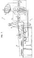
- Fig. 1 is a schematic, pictorial illustration of a mapping system 10, for real-time mapping of cardiac ablation treatment in a heart 24 of a subject 25, in accordance with a preferred embodiment of the present invention.
- System 10 comprises an elongated mapping probe, preferably a catheter 30, which is inserted by a user 22 through a vein or artery of the subject into a chamber of the heart.
- Fig. 2 is a schematic, pictorial illustration showing a distal portion of catheter 30, which is inserted into heart 24.
- Catheter 30 preferably comprises at least one position sensor 40, a tip electrode 48, and one or more temperature sensors 49, all of which are preferably fixed at or near a distal tip 44 of the catheter. Temperature sensors 49 may comprise, for example, thermocouples and/or thermistors.
- Position sensor 40 generates or receives signals used to determine the position and orientation of catheter 40 within the chamber of the heart.
- Tip electrode 48 is preferably configured to apply electrical signals to heart 24 for ablating cardiac tissue, and is preferably further configured for diagnostic purposes such as cardiac mapping. Alternatively, separate electrodes are provided for diagnostic purposes and for ablating cardiac tissue.
- catheter 30 further comprises at least one additional position sensor (not shown).
- Suitable position sensors are described, for example, in the above-cited US Patent 5,391,199 , the above-cited European Patent 0 776 176 , European Patent Applications 1,321 , 097 and 1,325,708 .
- a preferred electromagnetic mapping sensor and system is manufactured by Biosense Webster (Israel) Ltd., (Tirat Hacarmel, Israel) and marketed under the trade designations NOGATM and CARTOTM.
- substantially any other suitable type of position/coordinate sensing device known in the art is used for position sensing.
- catheter 30 is marked with one or more markers whose positions can be determined from outside of the body. Suitable markers include radio-opaque markers to facilitate fluoroscopic measurements.
- Position sensing techniques are used that achieve continuous generation of up to six dimensions of location and orientation information with respect to sensors 40.
- Position sensing techniques are used that achieve continuous generation of up to six dimensions of location and orientation information with respect to sensors 40.
- Positioning information as used in the context of the present patent application and in the claims, is to be understood as being indicative of the combination of location and orientation information, unless the context clearly indicates otherwise.
- mapping system 10 comprises a display monitor 52 and a console 20, which preferably comprises a location system control unit 36, an ablation power generator 38, a junction box 32, an electrocardiogram (ECG) recording and/or monitoring system 34, and a computer 50, which preferably comprises appropriate signal processing circuits that are typically contained inside a housing of the computer.
- Computer 50 is preferably programmed in software and/or hardware to carry out the functions described herein. This software may be downloaded to the computer in electronic form, over a network, for example, or it may alternatively be provided on tangible media, such as magnetic or optical media or other non-volatile memory.
- computer 50 comprises a general-purpose computer.
- Junction box 32 preferably routes (a) conducting wires and temperature sensor signals from catheter 30 to ablation power generator 38, (b) location sensor information from sensor 40 of catheter 30 to location system control unit 36, and (c) the diagnostic electrode signals generated by tip electrode 48 to ECG monitor 34. Alternatively or additionally, junction box 32 routes one or more of these signals directly to computer 50.
- ECG monitor 34 is preferably also coupled to receive signals from one or more body surface electrodes, so as to provide an ECG synchronization signal to computer 50.
- a location system 11 preferably comprises a set of external radiators 28, position sensor 40 of catheter 30 and any additional position sensors, and location system control unit 36.
- External radiators 28 are preferably adapted to be located at respective positions external to subject 25 and to generate fields, such as electromagnetic fields, towards position sensor 40, which is adapted to detect the fields and facilitate a calculation of its position coordinates by location system control unit 36 responsive to the fields.
- position sensor 40 generates fields, which are detected by external radiators 28.
- a reference position sensor typically either on an externally-applied reference patch attached to the exterior of the body of the subject, or on an internally-placed catheter, is maintained in a generally fixed position relative to heart 24. By comparing the position of catheter 30 to that of the reference catheter, the coordinates of catheter 30 are accurately determined relative to the heart, irrespective of motion of the subject. Alternatively, any other suitable method may be used to compensate for such motion.
- Location system control unit 36 receives signals from position sensor 40 (or from external radiators 28 when position sensor 40 generates the energy fields), calculates the location of sensor 40 and catheter 30, and transmits to computer 50 the location information and energy dose information (received from ablation power generator 38, as described below) which relates to the location information.
- the location system control unit preferably generates and transmits location information (a) essentially continuously, (b) between about one and 10 times per second, or (c) once per cardiac cycle.
- Ablation power generator 38 preferably generates power used by tip electrode 48 to perform ablation.
- the ablation power generator generates RF power for performing RF ablation.
- the ablation power generator induces ablation by means of other ablation techniques, such as laser ablation, cryogenic ablation, ultrasound ablation, radioactivity-induced ablation, or chemically-induced ablation.
- suitable feedback techniques are applied to facilitate identifying ablated regions on the cardiac map.
- ablation power generator 38 measures one or more of the following: (a) the temperature of temperature sensors 49, (b) the power applied to the tissue of the cardiac chamber by tip electrode 48, and (c) a measure of impedance, as described below (together, the "energy dose information").
- the ablation power generator transmits this energy dose information and preferably over a serial communications line, to location system control unit 46 and/or ECG monitor 34. Alternatively or additionally, the ablation power generator transmits some or all of this information directly to computer 50.
- the ablation power generator preferably measures and transmits the energy dose information (a) essentially continuously, (b) between about one and 10 times per second, or (c) once per cardiac cycle.
- tip electrode 48 comprises a monopolar electrode.
- mapping system 10 preferably further comprises a back-pad electrode 26 to complete the electrical circuit created by the mapping system.
- the back-pad electrode is preferably positioned to be in contact with the skin of the back of subject 25, adjacent to heart 24 during the procedure.
- the measure of impedance is preferably measured between tip electrode 48 and back-pad electrode 26.
- tip electrode 48 comprises a bipolar or multipolar electrode, in which case the measure of impedance is preferably measured between the poles of the electrode.
- catheter 30 prior to a cardiac ablation procedure, catheter 30 is inserted into the chamber of heart 24, and is used to acquire and record geometric and electrical information about the surface of the chamber of the heart.
- position and electrical information is acquired at an easily-identifiable annotation point in time, over a number of cardiac cycles.
- a geometric and electrical map (an "electroanatomical activation map") based thereupon is generated, preferably using techniques described in the above-cited US Patents 6,226,542 and 6,301,496 , European patent applications EP 1 125 549 and EP 1 166 714 , adapted for use with the techniques described herein.
- electrical signals from the electrodes are measured using techniques described in European patent applicaton EP 1 240 868 .
- an electroanatomical voltage amplitude map is acquired.
- a cardiac map generated during a previous cardiac procedure is used.
- a cardiac map is acquired from another source, such as an imaging modality (e.g., fluoroscopy, MRI, echocardiography, CT, single-photon computed tomography (SPECT), or positron emission tomography (PET)), and the location of the catheter is visualized on this map.
- an imaging modality e.g., fluoroscopy, MRI, echocardiography, CT, single-photon computed tomography (SPECT), or positron emission tomography (PET)
- SPECT single-photon computed tomography
- PET positron emission tomography
- computer 50 marks the ablation lesion locations on this map.
- a cardiac map is not acquired, in which case only a map of the ablation lesion is generated, as described below.
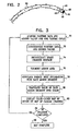
- Fig. 3 is a flow chart that schematically illustrates a method for mapping a lesion formed in a cardiac chamber, in accordance with a preferred embodiment of the present invention.
- user 22 advances catheter 30 to the area of the surface of the cardiac chamber on which ablation is to be performed.
- ablation power generator 38 measures, preferably continuously, the energy dose information, as described above.
- computer 50 receives (a) location information for the position of tip 44 of catheter 30 at the annotation point in the cardiac cycle and (b) energy dose information acquired during the cardiac cycle, at an acquisition and synchronization step 70.
- the computer For each cardiac cycle during which ablation is performed, the computer uses the location information to calculate a three-dimensional ablation mapping point.
- the computer uses an ECG signal generated by ECG monitor 34 for synchronizing the location information with the energy dose information.
- the computer For each cardiac cycle, the computer preferably associates the location of tip 44 at the annotation point with the series of measurements, at a synchronization step 72.
- a chamber reconstruction step 74 computer 50 generates a three-dimensional surface that connects the ablation mapping points generated at each iteration of step 70.
- techniques described above with respect to generating a cardiac map are used. If a map of the cardiac surface was acquired prior to beginning ablation, these ablation mapping points are preferably added to this existing map.
- the surface area of the ablation lesion reconstruction is segmented into small planar segments, preferably triangles, at a segmentation step 76.
- these triangular segments have an average side length of about 3 millimeters, because such an area is generally large enough to contain at least one ablation mapping point.
- the mapping volume is segmented into a grid of voxels, with each voxel segment preferably having dimensions of 2 millimeters by 2 millimeters by 2 millimeters.
- Computer 50 generates display values for each segment, responsive to the energy dose information of the ablation mapping points within the segment, at a dose/segment association step 78.
- user 22 selects one of several functions for the computer to use for generating the display values for each segment. Examples of such functions include:
- the segments comprise voxels, as described above, and a weighted display value is calculated for each segment.
- the weighted display value equals a weighted average of the display value of the segment and the display values of neighboring segments, with the weighting of each neighboring segment decreasing with distance from the segment.
- the weighted display value for a segment may equal the sum of (a) the display value of the segment, (b) one half of the display values of once-removed segments, (c) one quarter of the display values of twice-removed segments, and (d) one eighth of the display values of thrice-removed segments, as shown in the following grid where x represents the display value of each of the segments: 1/8 x 1/8 x 1/8 x 1/8 x 1/8 x 1/8 x 1/8 x 1/8 x 1/4 x 1/4 x 1/4 x 1/4 x 1/8 x 1/4 x 1/2 x 1/2 x 1/2 x 1/4 x 1/8 x 1/8 x 1/4 x 1/2 x 1/2 x 1/4 x 1/8 x 1/8 x 1/4 x 1/2 x 1/2 x 1/4 x 1/8 x 1/8 x 1/4 x 1/2 x 1/2 x 1/4 x 1/8 x 1/8 x 1/4 x 1/2 x 1/2 x 1/4 x 1/8 x 1/8 x 1/4
- the weighting is calculated in three dimensions. If the same weighting factors are used as in the preceding two-dimensional example, the weighted display values are preferably normalized by dividing the sum by 65.75. Preferably, weighting multipliers are determined based on empirical data regarding the actual thermal conduction of ablation energy and resulting ablation lesions in neighboring segments.
- the segments preferably comprise voxels with a relatively fine grid, such as 1 millimeter by 1 millimeter by 1 millimeter.
- This weighted-average approach is particularly useful when the display values are based on energy dose values, temperature values, and/or average impedance values, as described above.
- the application of a weighted average simulates thermal conduction that occurs in tissue.
- Computer 50 translates the display value or weighted display value, as appropriate, of each segment into color using a color scale, at a color translation step 80.
- Computer 50 then displays on display monitor 52 the three-dimensional reconstruction of the ablation lesion with the segments colored based on their display values or weighted display values, at a map display step 82.
- Example color scales include a grayscale (ranging from black, representing the lowest value to progressively lighter shades of gray to white, representing the highest value) or a hot iron color scale (ranging from black, representing the lowest value, to blue to red to yellow to white, representing the highest value).
- the colors of the color scale are not assigned pre-set ranges of display values.
- the ranges are preferably auto-scaled responsive to the total range of display values for a given ablation map. If a cardiac map was acquired prior to beginning ablation, the color-coded segments are preferably overlaid on this pre-acquired map and displayed together on display monitor 52.
- user 22 determines that a particular site or region has not been sufficiently ablated, he can immediately return to the site and repeat the ablation procedure.
- Computer 50 checks whether the ablation procedure is concluded, at a completion check step 84. If not, the steps of Fig. 3 are repeated for each cardiac cycle until the ablation procedure is concluded. If ablation has been concluded, then the computer ceases mapping, at a map completion step 86. As a result of the steps shown in Fig. 3 , a real-time three-dimensional representation of the ablation lesion is generated for user 22 as the ablation procedure is being performed.
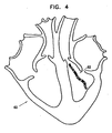
- Fig. 4 is a schematic, pictorial representation of a sample, highly simplified black-and-white ablation lesion map 62 on a calculated or estimated map 60 of a cardiac chamber, in accordance with a preferred embodiment of the present invention.
- the various shadings of the plotted ablation mapping points of map 62 symbolically represent the color scale of the points. It will be appreciated that actual maps generated are preferably in color.
- the present application discloses a method for ablating tissue in a heart of a subject during an ablation procedure, comprising:
- the method includes applying the local treatment by applying a cryogenic source to induce ablation.
- the method includes applying the local treatment by applying a radioactive source to induce ablation.
- the method includes applying the local treatment by applying a chemical to induce ablation.
- the method comprises designating the indications of the respective levels of ablation at the sites by translating each indication into a color on a color scale.
- displaying the map comprises displaying an electroanatomical activation map.
- displaying the map comprises displaying an electroanatomical voltage amplitude map.
- displaying the map comprises displaying a map generated using a modality selected from the list consisting of: CT scanning, magnetic resonance imaging, fluoroscopy, echocardiography, single-photon computed tomography, and positron emission tomography.
- a modality selected from the list consisting of: CT scanning, magnetic resonance imaging, fluoroscopy, echocardiography, single-photon computed tomography, and positron emission tomography.
- sensing at each respective site the parameter that is indicative of the level of ablation at the site comprises calculating a weighted average of levels of ablation at the site and at secondary sites in a vicinity of the site, wherein the weighting of each secondary site decreases as the distance of the secondary site from the site increases.
- the method comprises segmenting a mapping volume including the sites into voxels, wherein designating the indications of the respective levels of ablation at the sites comprises designating the indications with respect to respective voxels of the mapping volume.
- sensing the parameter comprises sensing a measure of electrical impedance at the site.
- the method comprises segmenting a surface area including the sites into planar segments, wherein designating the indications of the respective levels of ablation at the sites comprises designating the indications with respect to respective planar segments of the surface area.
- segmenting the surface area comprises segmenting the surface area into triangular segments.
- applying the local treatment comprises applying energy to the heart.
- applying the energy comprises applying radiofrequency energy.
- applying the energy comprises applying energy generated by a laser.
- applying the energy comprises applying ultrasound energy.
- sensing the parameter comprises sensing a measure of the energy applied at the site.
- sensing the parameter comprises calculating a measure of a total amount of energy applied at the site.
- sensing the parameter comprises sensing a temperature of the site.
- sensing the parameter comprises determining a maximum temperature sensed at the site.
- sensing the parameter comprises determining a maximal temperature time-gradient at the site.
- the application also discloses a method for ablating tissue in an organ of a subject, comprising:
- the organ includes a liver of the subject, and wherein applying the local treatment comprises applying the treatment to the liver.
- the organ includes a prostate of the subject, and wherein applying the local treatment comprises applying the treatment to the prostate.
- the organ includes a breast of the subject, and wherein applying the local treatment comprises applying the treatment to the breast.
Landscapes
- Health & Medical Sciences (AREA)
- Life Sciences & Earth Sciences (AREA)
- Surgery (AREA)
- Engineering & Computer Science (AREA)
- General Health & Medical Sciences (AREA)
- Nuclear Medicine, Radiotherapy & Molecular Imaging (AREA)
- Animal Behavior & Ethology (AREA)
- Public Health (AREA)
- Veterinary Medicine (AREA)
- Biomedical Technology (AREA)
- Heart & Thoracic Surgery (AREA)
- Medical Informatics (AREA)
- Molecular Biology (AREA)
- Otolaryngology (AREA)
- Plasma & Fusion (AREA)
- Physics & Mathematics (AREA)
- Cardiology (AREA)
- Robotics (AREA)
- Surgical Instruments (AREA)
- Measurement And Recording Of Electrical Phenomena And Electrical Characteristics Of The Living Body (AREA)
- Electrotherapy Devices (AREA)
- Magnetic Resonance Imaging Apparatus (AREA)
- Laser Surgery Devices (AREA)
- Ultra Sonic Daignosis Equipment (AREA)
Applications Claiming Priority (2)
| Application Number | Priority Date | Filing Date | Title |
|---|---|---|---|
| US277079 | 1994-07-19 | ||
| US10/277,079 US7001383B2 (en) | 2002-10-21 | 2002-10-21 | Real-time monitoring and mapping of ablation lesion formation in the heart |
Publications (3)
| Publication Number | Publication Date |
|---|---|
| EP1415608A2 EP1415608A2 (en) | 2004-05-06 |
| EP1415608A3 EP1415608A3 (en) | 2004-10-20 |
| EP1415608B1 true EP1415608B1 (en) | 2009-02-18 |
Family
ID=32093212
Family Applications (1)
| Application Number | Title | Priority Date | Filing Date |
|---|---|---|---|
| EP03256602A Expired - Lifetime EP1415608B1 (en) | 2002-10-21 | 2003-10-20 | Real-time monitoring and mapping of ablation lesion formation in the heart |
Country Status (12)
| Country | Link |
|---|---|
| US (1) | US7001383B2 (https=) |
| EP (1) | EP1415608B1 (https=) |
| JP (1) | JP4509527B2 (https=) |
| KR (1) | KR20040036867A (https=) |
| AT (1) | ATE422849T1 (https=) |
| AU (1) | AU2003255201B2 (https=) |
| CA (1) | CA2445360C (https=) |
| DE (1) | DE60326202D1 (https=) |
| DK (1) | DK1415608T3 (https=) |
| ES (1) | ES2319976T3 (https=) |
| IL (1) | IL158545A (https=) |
| PT (1) | PT1415608E (https=) |
Cited By (5)
| Publication number | Priority date | Publication date | Assignee | Title |
|---|---|---|---|---|
| EP3122246B1 (en) * | 2014-03-25 | 2022-05-04 | Acutus Medical, Inc. | Cardiac analysis user interface system and method |
| US11786300B2 (en) | 2021-04-07 | 2023-10-17 | Btl Medical Technologies S.R.O. | Pulsed field ablation device and method |
| US11896298B2 (en) | 2021-07-06 | 2024-02-13 | Btl Medical Development A.S. | Pulsed field ablation device and method |
| US12076067B2 (en) | 2022-10-05 | 2024-09-03 | Btl Medical Development A.S. | Pulsed field ablation device and method |
| EP4708209A1 (en) * | 2024-09-03 | 2026-03-11 | Biosense Webster (Israel) Ltd. | High-resolution high-dynamic-range pfa map |
Families Citing this family (231)
| Publication number | Priority date | Publication date | Assignee | Title |
|---|---|---|---|---|
| US8361067B2 (en) | 2002-09-30 | 2013-01-29 | Relievant Medsystems, Inc. | Methods of therapeutically heating a vertebral body to treat back pain |
| US7306593B2 (en) * | 2002-10-21 | 2007-12-11 | Biosense, Inc. | Prediction and assessment of ablation of cardiac tissue |
| US8862204B2 (en) * | 2002-11-18 | 2014-10-14 | Mediguide Ltd. | Reducing mechanical stress on conductors and connection points in a position determinable interventional medical device |
| ATE523141T1 (de) * | 2004-02-17 | 2011-09-15 | Philips Electronics Ltd | Verfahren und vorrichtung zur registrierung, verifizierung von und bezugnahme auf körperorgane(n) |
| CA2586560A1 (en) * | 2004-11-05 | 2006-06-01 | The Government Of The United States Of America, As Represented By The Se Cretary, Department Of Health And Human Services | Access system |
| US7805269B2 (en) * | 2004-11-12 | 2010-09-28 | Philips Electronics Ltd | Device and method for ensuring the accuracy of a tracking device in a volume |
| US7751868B2 (en) * | 2004-11-12 | 2010-07-06 | Philips Electronics Ltd | Integrated skin-mounted multifunction device for use in image-guided surgery |
| EP1838215B1 (en) * | 2005-01-18 | 2012-08-01 | Philips Electronics LTD | Electromagnetically tracked k-wire device |
| US7715604B2 (en) * | 2005-01-18 | 2010-05-11 | Siemens Medical Solutions Usa, Inc. | System and method for automatically registering three dimensional cardiac images with electro-anatomical cardiac mapping data |
| US8611983B2 (en) * | 2005-01-18 | 2013-12-17 | Philips Electronics Ltd | Method and apparatus for guiding an instrument to a target in the lung |
| CA2605360C (en) | 2005-04-21 | 2017-03-28 | Asthmatx, Inc. | Control methods and devices for energy delivery |
| US7588567B2 (en) * | 2005-04-22 | 2009-09-15 | Abl Technologies, Llc | Method and system of stopping energy delivery of an ablation procedure with a computer based device for increasing safety of ablation procedures |
| US20050203502A1 (en) * | 2005-04-22 | 2005-09-15 | Boveja Birinder R. | Method and system for monitoring atrial fibrillation ablations with an ablation interface device |
| WO2008045016A2 (en) * | 2005-06-21 | 2008-04-17 | Traxtal Inc. | Device and method for a trackable ultrasound |
| EP1898775B1 (en) * | 2005-06-21 | 2013-02-13 | Philips Electronics LTD | System and apparatus for navigated therapy and diagnosis |
| US7740584B2 (en) * | 2005-08-16 | 2010-06-22 | The General Electric Company | Method and system for mapping physiology information onto ultrasound-based anatomic structure |
| EP1924197B1 (en) * | 2005-08-24 | 2017-10-11 | Philips Electronics LTD | System for navigated flexible endoscopy |
| EP1922005B1 (en) * | 2005-08-25 | 2011-12-21 | Koninklijke Philips Electronics N.V. | System for electrophysiology regaining support to continue line and ring ablations |
| US20070078453A1 (en) * | 2005-10-04 | 2007-04-05 | Johnson Kristin D | System and method for performing cardiac ablation |
| JP5227180B2 (ja) * | 2005-12-02 | 2013-07-03 | コーニンクレッカ フィリップス エレクトロニクス エヌ ヴィ | アブレーション手順を自動化して人の手の介入の必要性を最少化する方法及び装置 |
| US9492226B2 (en) | 2005-12-06 | 2016-11-15 | St. Jude Medical, Atrial Fibrillation Division, Inc. | Graphical user interface for real-time RF lesion depth display |
| US8603084B2 (en) * | 2005-12-06 | 2013-12-10 | St. Jude Medical, Atrial Fibrillation Division, Inc. | System and method for assessing the formation of a lesion in tissue |
| US8406866B2 (en) | 2005-12-06 | 2013-03-26 | St. Jude Medical, Atrial Fibrillation Division, Inc. | System and method for assessing coupling between an electrode and tissue |
| US8403925B2 (en) | 2006-12-06 | 2013-03-26 | St. Jude Medical, Atrial Fibrillation Division, Inc. | System and method for assessing lesions in tissue |
| US9254163B2 (en) | 2005-12-06 | 2016-02-09 | St. Jude Medical, Atrial Fibrillation Division, Inc. | Assessment of electrode coupling for tissue ablation |
| US8369922B2 (en) | 2005-12-06 | 2013-02-05 | St. Jude Medical Atrial Fibrillation Division, Inc. | Method for displaying catheter electrode-tissue contact in electro-anatomic mapping and navigation system |
| US10362959B2 (en) | 2005-12-06 | 2019-07-30 | St. Jude Medical, Atrial Fibrillation Division, Inc. | System and method for assessing the proximity of an electrode to tissue in a body |
| WO2007070361A2 (en) | 2005-12-06 | 2007-06-21 | St. Jude Medical, Atrial Fibrillation Division, Inc. | Assessment of electrode coupling for tissue ablation |
| US7918850B2 (en) | 2006-02-17 | 2011-04-05 | Biosense Wabster, Inc. | Lesion assessment by pacing |
| US7749249B2 (en) | 2006-02-21 | 2010-07-06 | Kardium Inc. | Method and device for closing holes in tissue |
| US7996059B2 (en) * | 2006-03-08 | 2011-08-09 | Biosense Webster, Inc. | Esophagus imaging enhancement device |
| DE102006013475A1 (de) * | 2006-03-23 | 2007-09-27 | Siemens Ag | Vorrichtung und Verfahren zur Synchronisation einer Bilderfassungsvorrichtung mit einem ersten, älteren Bilddatensatz |
| DE102006013476B4 (de) * | 2006-03-23 | 2012-11-15 | Siemens Ag | Verfahren zur positionsgenauen Darstellung von interessierenden Gewebebereichen |
| US20070270688A1 (en) | 2006-05-19 | 2007-11-22 | Daniel Gelbart | Automatic atherectomy system |
| US8449605B2 (en) | 2006-06-28 | 2013-05-28 | Kardium Inc. | Method for anchoring a mitral valve |
| US10028783B2 (en) | 2006-06-28 | 2018-07-24 | Kardium Inc. | Apparatus and method for intra-cardiac mapping and ablation |
| US9119633B2 (en) | 2006-06-28 | 2015-09-01 | Kardium Inc. | Apparatus and method for intra-cardiac mapping and ablation |
| US8920411B2 (en) * | 2006-06-28 | 2014-12-30 | Kardium Inc. | Apparatus and method for intra-cardiac mapping and ablation |
| US11389232B2 (en) | 2006-06-28 | 2022-07-19 | Kardium Inc. | Apparatus and method for intra-cardiac mapping and ablation |
| US7728868B2 (en) | 2006-08-02 | 2010-06-01 | Inneroptic Technology, Inc. | System and method of providing real-time dynamic imagery of a medical procedure site using multiple modalities |
| US7837610B2 (en) | 2006-08-02 | 2010-11-23 | Kardium Inc. | System for improving diastolic dysfunction |
| US8641660B2 (en) * | 2006-10-04 | 2014-02-04 | P Tech, Llc | Methods and devices for controlling biologic microenvironments |
| US9403029B2 (en) | 2007-07-18 | 2016-08-02 | Visualase, Inc. | Systems and methods for thermal therapy |
| US8131379B2 (en) * | 2007-08-27 | 2012-03-06 | St. Jude Medical Atrial Fibrillation Division, Inc. | Cardiac tissue elasticity sensing |
| KR100957713B1 (ko) * | 2007-10-16 | 2010-05-12 | 주식회사 사이버메드 | 수술용 항법 장치의 작동 방법 |
| US8906011B2 (en) | 2007-11-16 | 2014-12-09 | Kardium Inc. | Medical device for use in bodily lumens, for example an atrium |
| US8359092B2 (en) * | 2007-11-29 | 2013-01-22 | Biosense Webster, Inc. | Determining locations of ganglia and plexi in the heart using complex fractionated atrial electrogram |
| US9204927B2 (en) * | 2009-05-13 | 2015-12-08 | St. Jude Medical, Atrial Fibrillation Division, Inc. | System and method for presenting information representative of lesion formation in tissue during an ablation procedure |
| US8290578B2 (en) | 2007-12-28 | 2012-10-16 | St. Jude Medical, Atrial Fibrillation Division, Inc. | Method and apparatus for complex impedance compensation |
| WO2009094646A2 (en) | 2008-01-24 | 2009-07-30 | The University Of North Carolina At Chapel Hill | Methods, systems, and computer readable media for image guided ablation |
| US8489172B2 (en) * | 2008-01-25 | 2013-07-16 | Kardium Inc. | Liposuction system |
| US8340379B2 (en) | 2008-03-07 | 2012-12-25 | Inneroptic Technology, Inc. | Systems and methods for displaying guidance data based on updated deformable imaging data |
| US20090287304A1 (en) * | 2008-05-13 | 2009-11-19 | Kardium Inc. | Medical Device for Constricting Tissue or a Bodily Orifice, for example a mitral valve |
| EP2163218A1 (fr) * | 2008-09-16 | 2010-03-17 | Osyris Medical | Appareil de traitement d'une partie de corps humain ou animal, comportant un instrument permettant de délivrer et/ou un instrument permettant d'aspirer localement des doses de traitement et des moyens de controle de dosimétrie |
| US10028753B2 (en) | 2008-09-26 | 2018-07-24 | Relievant Medsystems, Inc. | Spine treatment kits |
| CA2957010C (en) | 2008-09-26 | 2017-07-04 | Relievant Medsystems, Inc. | Systems and methods for navigating an instrument through bone |
| US9192789B2 (en) * | 2008-10-30 | 2015-11-24 | Vytronus, Inc. | System and method for anatomical mapping of tissue and planning ablation paths therein |
| WO2010058372A1 (en) * | 2008-11-24 | 2010-05-27 | Koninklijke Philips Electronics N.V. | Imaging apparatus for imaging a heart |
| US9554774B2 (en) | 2008-12-08 | 2017-01-31 | Acist Medical Systems, Inc. | System and catheter for image guidance and methods thereof |
| US20100168557A1 (en) * | 2008-12-30 | 2010-07-01 | Deno D Curtis | Multi-electrode ablation sensing catheter and system |
| US8900150B2 (en) | 2008-12-30 | 2014-12-02 | St. Jude Medical, Atrial Fibrillation Division, Inc. | Intracardiac imaging system utilizing a multipurpose catheter |
| US8948476B2 (en) * | 2010-12-20 | 2015-02-03 | St. Jude Medical, Atrial Fibrillation Division, Inc. | Determination of cardiac geometry responsive to doppler based imaging of blood flow characteristics |
| US9610118B2 (en) | 2008-12-31 | 2017-04-04 | St. Jude Medical, Atrial Fibrillation Division, Inc. | Method and apparatus for the cancellation of motion artifacts in medical interventional navigation |
| US8945117B2 (en) | 2009-02-11 | 2015-02-03 | Boston Scientific Scimed, Inc. | Insulated ablation catheter devices and methods of use |
| US8690776B2 (en) | 2009-02-17 | 2014-04-08 | Inneroptic Technology, Inc. | Systems, methods, apparatuses, and computer-readable media for image guided surgery |
| US11464578B2 (en) | 2009-02-17 | 2022-10-11 | Inneroptic Technology, Inc. | Systems, methods, apparatuses, and computer-readable media for image management in image-guided medical procedures |
| US8554307B2 (en) | 2010-04-12 | 2013-10-08 | Inneroptic Technology, Inc. | Image annotation in image-guided medical procedures |
| US8641621B2 (en) | 2009-02-17 | 2014-02-04 | Inneroptic Technology, Inc. | Systems, methods, apparatuses, and computer-readable media for image management in image-guided medical procedures |
| US9808323B2 (en) | 2009-06-04 | 2017-11-07 | Koninklijke Philips N.V. | Visualization apparatus |
| US9259290B2 (en) | 2009-06-08 | 2016-02-16 | MRI Interventions, Inc. | MRI-guided surgical systems with proximity alerts |
| WO2010148083A2 (en) | 2009-06-16 | 2010-12-23 | Surgivision, Inc. | Mri-guided devices and mri-guided interventional systems that can track and generate dynamic visualizations of the devices in near real time |
| WO2011008444A1 (en) | 2009-06-30 | 2011-01-20 | Boston Scientific Scimed, Inc. | Map and ablate open irrigated hybrid catheter |
| CN102469976B (zh) * | 2009-07-06 | 2015-02-18 | 皇家飞利浦电子股份有限公司 | 生理参数的可视化 |
| GB2485924B (en) * | 2009-09-15 | 2015-11-04 | Boston Scient Scimed Inc | System for predicting lesion size shortly after onset of RF energy delivery |
| CN102497822B (zh) | 2009-09-17 | 2015-02-11 | 皇家飞利浦电子股份有限公司 | 具有远端处的温度探测的医学超声设备 |
| EP2482749B1 (en) | 2009-10-01 | 2017-08-30 | Kardium Inc. | Kit for constricting tissue or a bodily orifice, for example, a mitral valve |
| WO2011044248A2 (en) * | 2009-10-06 | 2011-04-14 | Cardiofocus, Inc. | Cardiac ablation image analysis system and process |
| US20110082351A1 (en) * | 2009-10-07 | 2011-04-07 | Inneroptic Technology, Inc. | Representing measurement information during a medical procedure |
| US8454589B2 (en) * | 2009-11-20 | 2013-06-04 | St. Jude Medical, Atrial Fibrillation Division, Inc. | System and method for assessing effective delivery of ablation therapy |
| US8926604B2 (en) * | 2009-12-23 | 2015-01-06 | Biosense Webster (Israel) Ltd. | Estimation and mapping of ablation volume |
| US9962217B2 (en) | 2009-12-23 | 2018-05-08 | Biosense Webster (Israel) Ltd. | Estimation and mapping of ablation volume |
| US8568404B2 (en) * | 2010-02-19 | 2013-10-29 | Covidien Lp | Bipolar electrode probe for ablation monitoring |
| US9241762B2 (en) | 2010-06-03 | 2016-01-26 | Covidien Lp | Specific absorption rate measurement and energy-delivery device characterization using image analysis |
| US9468492B2 (en) | 2010-06-03 | 2016-10-18 | Covidien Lp | Specific absorption rate measurement and energy-delivery device characterization using image analysis |
| US9377367B2 (en) | 2010-06-03 | 2016-06-28 | Covidien Lp | Specific absorption rate measurement and energy-delivery device characterization using thermal phantom and image analysis |
| US8188435B2 (en) | 2010-06-03 | 2012-05-29 | Tyco Healthcare Group Lp | Specific absorption rate measurement and energy-delivery device characterization using thermal phantom and image analysis |
| US11490957B2 (en) | 2010-06-16 | 2022-11-08 | Biosense Webster (Israel) Ltd. | Spectral sensing of ablation |
| US10314650B2 (en) | 2010-06-16 | 2019-06-11 | Biosense Webster (Israel) Ltd. | Spectral sensing of ablation |
| US10765882B2 (en) * | 2010-09-05 | 2020-09-08 | Madryn Heatlh Partners, Lp | Self operated esthetic device with a substrate |
| US8940002B2 (en) | 2010-09-30 | 2015-01-27 | Kardium Inc. | Tissue anchor system |
| US9089340B2 (en) | 2010-12-30 | 2015-07-28 | Boston Scientific Scimed, Inc. | Ultrasound guided tissue ablation |
| US11259867B2 (en) | 2011-01-21 | 2022-03-01 | Kardium Inc. | High-density electrode-based medical device system |
| US9486273B2 (en) | 2011-01-21 | 2016-11-08 | Kardium Inc. | High-density electrode-based medical device system |
| CA2764494A1 (en) | 2011-01-21 | 2012-07-21 | Kardium Inc. | Enhanced medical device for use in bodily cavities, for example an atrium |
| US9452016B2 (en) | 2011-01-21 | 2016-09-27 | Kardium Inc. | Catheter system |
| US9757044B2 (en) | 2011-03-10 | 2017-09-12 | Acutus Medical, Inc. | Device and method for the geometric determination of electrical dipole densities on the cardiac wall |
| US9072511B2 (en) | 2011-03-25 | 2015-07-07 | Kardium Inc. | Medical kit for constricting tissue or a bodily orifice, for example, a mitral valve |
| US10039502B2 (en) * | 2011-04-12 | 2018-08-07 | Medtronic Ablation Frontiers Llc | Electrophysiological signal processing and utilization |
| US9241687B2 (en) | 2011-06-01 | 2016-01-26 | Boston Scientific Scimed Inc. | Ablation probe with ultrasonic imaging capabilities |
| AU2012308464B2 (en) | 2011-09-14 | 2016-10-20 | Boston Scientific Scimed, Inc. | Ablation device with ionically conductive balloon |
| EP2755587B1 (en) | 2011-09-14 | 2018-11-21 | Boston Scientific Scimed, Inc. | Ablation device with multiple ablation modes |
| ES2727868T3 (es) | 2011-09-22 | 2019-10-21 | Univ George Washington | Sistemas para visualizar el tejido ablacionado |
| CN104066368B (zh) | 2011-09-22 | 2017-02-22 | 乔治华盛顿大学 | 用于使经消融组织可视化的系统和方法 |
| WO2013102072A1 (en) | 2011-12-28 | 2013-07-04 | Boston Scientific Scimed, Inc. | Ablation probe with ultrasonic imaging capability |
| WO2013101772A1 (en) | 2011-12-30 | 2013-07-04 | Relievant Medsystems, Inc. | Systems and methods for treating back pain |
| CA2860636A1 (en) | 2012-01-10 | 2013-07-18 | Boston Scientific Scimed, Inc. | Electrophysiology system |
| USD777925S1 (en) | 2012-01-20 | 2017-01-31 | Kardium Inc. | Intra-cardiac procedure device |
| USD777926S1 (en) | 2012-01-20 | 2017-01-31 | Kardium Inc. | Intra-cardiac procedure device |
| WO2013116240A1 (en) | 2012-01-30 | 2013-08-08 | Inneroptic Technology, Inc. | Multiple medical device guidance |
| US8945015B2 (en) | 2012-01-31 | 2015-02-03 | Koninklijke Philips N.V. | Ablation probe with fluid-based acoustic coupling for ultrasonic tissue imaging and treatment |
| US8900225B2 (en) * | 2012-05-07 | 2014-12-02 | Biosense Webster (Israel) Ltd. | Automatic ablation tracking |
| US10827977B2 (en) | 2012-05-21 | 2020-11-10 | Kardium Inc. | Systems and methods for activating transducers |
| US9017321B2 (en) | 2012-05-21 | 2015-04-28 | Kardium, Inc. | Systems and methods for activating transducers |
| US9198592B2 (en) | 2012-05-21 | 2015-12-01 | Kardium Inc. | Systems and methods for activating transducers |
| JP6301926B2 (ja) | 2012-08-09 | 2018-03-28 | ユニバーシティ オブ アイオワ リサーチ ファウンデーション | カテーテル、カテーテルシステム、及び組織構造を刺通する方法 |
| EP2890292B1 (en) | 2012-08-31 | 2021-01-13 | Acutus Medical, Inc. | Catheter system for the heart |
| US10588691B2 (en) | 2012-09-12 | 2020-03-17 | Relievant Medsystems, Inc. | Radiofrequency ablation of tissue within a vertebral body |
| CA2889478C (en) | 2012-11-05 | 2020-11-24 | Relievant Medsystems, Inc. | Systems and methods for creating curved paths through bone and modulating nerves within the bone |
| US10314559B2 (en) | 2013-03-14 | 2019-06-11 | Inneroptic Technology, Inc. | Medical device guidance |
| US9703317B2 (en) | 2013-03-14 | 2017-07-11 | Biosense Webster (Israel) Ltd. | Dongle with shape memory |
| US9724151B2 (en) | 2013-08-08 | 2017-08-08 | Relievant Medsystems, Inc. | Modulating nerves within bone using bone fasteners |
| WO2015038607A2 (en) | 2013-09-13 | 2015-03-19 | Acutus Medical, Inc. | Devices and methods for determination of electrical dipole densities on a cardiac surface |
| JP6737705B2 (ja) | 2013-11-14 | 2020-08-12 | ザ・ジョージ・ワシントン・ユニバーシティThe George Washingtonuniversity | 損傷部位の深さを決定するシステムの動作方法及び心臓組織の画像を生成するシステム |
| US20150141847A1 (en) | 2013-11-20 | 2015-05-21 | The George Washington University | Systems and methods for hyperspectral analysis of cardiac tissue |
| US9713456B2 (en) | 2013-12-30 | 2017-07-25 | Acist Medical Systems, Inc. | Position sensing in intravascular imaging |
| WO2015103574A1 (en) | 2014-01-06 | 2015-07-09 | Iowa Approach Inc. | Apparatus and methods for renal denervation ablation |
| US10083278B2 (en) * | 2014-02-12 | 2018-09-25 | Edda Technology, Inc. | Method and system for displaying a timing signal for surgical instrument insertion in surgical procedures |
| US9326693B2 (en) * | 2014-04-15 | 2016-05-03 | Biosense Webster (Israel) Ltd. | Placement of electrodes in proximity to the heart |
| EP4670627A3 (en) | 2014-05-07 | 2026-03-25 | Boston Scientific Scimed, Inc. | Methods and apparatus for selective tissue ablation |
| WO2015175944A1 (en) | 2014-05-16 | 2015-11-19 | Gary Long | Methods and apparatus for multi-catheter tissue ablation |
| US9757182B2 (en) | 2014-06-02 | 2017-09-12 | Biosense Webster (Israel) Ltd. | Identification and visualization of gaps between cardiac ablation sites |
| WO2015192018A1 (en) | 2014-06-12 | 2015-12-17 | Iowa Approach Inc. | Method and apparatus for rapid and selective tissue ablation with cooling |
| EP3154463B1 (en) | 2014-06-12 | 2019-03-27 | Farapulse, Inc. | Apparatus for rapid and selective transurethral tissue ablation |
| US9901406B2 (en) | 2014-10-02 | 2018-02-27 | Inneroptic Technology, Inc. | Affected region display associated with a medical device |
| WO2016061002A1 (en) | 2014-10-13 | 2016-04-21 | Boston Scientific Scimed Inc. | Tissue diagnosis and treatment using mini-electrodes |
| EP3206613B1 (en) | 2014-10-14 | 2019-07-03 | Farapulse, Inc. | Apparatus for rapid and safe pulmonary vein cardiac ablation |
| EP4316361A3 (en) | 2014-10-24 | 2024-05-01 | Boston Scientific Scimed Inc. | Medical devices with a flexible electrode assembly coupled to an ablation tip |
| EP3215002B1 (en) | 2014-11-03 | 2024-03-20 | The George Washington University | Systems for lesion assessment |
| JP6771731B2 (ja) | 2014-11-03 | 2020-10-21 | 460メディカル・インコーポレイテッド460Medical, Inc. | 接触性評価システム及び方法 |
| US10368936B2 (en) | 2014-11-17 | 2019-08-06 | Kardium Inc. | Systems and methods for selecting, activating, or selecting and activating transducers |
| US10722184B2 (en) | 2014-11-17 | 2020-07-28 | Kardium Inc. | Systems and methods for selecting, activating, or selecting and activating transducers |
| WO2016081650A1 (en) | 2014-11-19 | 2016-05-26 | Advanced Cardiac Therapeutics, Inc. | Ablation devices, systems and methods of using a high-resolution electrode assembly |
| EP3220844B1 (en) | 2014-11-19 | 2020-11-11 | EPiX Therapeutics, Inc. | Systems for high-resolution mapping of tissue |
| WO2016081611A1 (en) | 2014-11-19 | 2016-05-26 | Advanced Cardiac Therapeutics, Inc. | High-resolution mapping of tissue with pacing |
| US10188467B2 (en) | 2014-12-12 | 2019-01-29 | Inneroptic Technology, Inc. | Surgical guidance intersection display |
| US10271893B2 (en) * | 2014-12-15 | 2019-04-30 | Medtronic Ablation Frontiers Llc | Timed energy delivery |
| US9743854B2 (en) | 2014-12-18 | 2017-08-29 | Boston Scientific Scimed, Inc. | Real-time morphology analysis for lesion assessment |
| AU2015268674A1 (en) | 2014-12-29 | 2016-07-14 | Biosense Webster (Israel) Ltd. | Spectral sensing of ablation |
| US9636164B2 (en) | 2015-03-25 | 2017-05-02 | Advanced Cardiac Therapeutics, Inc. | Contact sensing systems and methods |
| EP3294179B1 (en) * | 2015-05-12 | 2024-04-17 | Navix International Limited | Lesion assessment by dielectric property analysis |
| WO2016181317A2 (en) | 2015-05-12 | 2016-11-17 | Navix International Limited | Calculation of an ablation plan |
| WO2016183285A1 (en) | 2015-05-12 | 2016-11-17 | Acutus Medical, Inc. | Ultrasound sequencing system and method |
| CN107847745B (zh) | 2015-05-13 | 2022-06-24 | 阿库图森医疗有限公司 | 用于采集和分析心脏信息的定位系统和方法 |
| US20160331262A1 (en) * | 2015-05-13 | 2016-11-17 | Ep Solutions Sa | Combined Electrophysiological Mapping and Cardiac Ablation Methods, Systems, Components and Devices |
| US10517670B2 (en) | 2015-07-16 | 2019-12-31 | Biosense Webster (Israel) Ltd. | Estimation of lesion size |
| US10779904B2 (en) | 2015-07-19 | 2020-09-22 | 460Medical, Inc. | Systems and methods for lesion formation and assessment |
| US9949700B2 (en) | 2015-07-22 | 2018-04-24 | Inneroptic Technology, Inc. | Medical device approaches |
| US11154186B2 (en) | 2015-07-31 | 2021-10-26 | University Of Utah Research Foundation | Devices, systems, and methods for imaging and treating a selected tissue |
| US20170065353A1 (en) * | 2015-09-04 | 2017-03-09 | Biosense Webster (Israel) Ltd. | Identifying and presenting suspected map shifts |
| ITUB20155830A1 (it) | 2015-11-23 | 2017-05-23 | R A W Srl | "sistema di navigazione, tracciamento, e guida per il posizionamento di strumenti operatori" |
| US10213253B2 (en) | 2015-12-24 | 2019-02-26 | Biosense Webster (Israel) Ltd. | Estimating a temperature during ablation |
| US12514632B2 (en) | 2015-12-30 | 2026-01-06 | Biozonal Id, Llc | Tissue mapping and treatment |
| WO2017117582A1 (en) | 2015-12-30 | 2017-07-06 | Schuler Scientific Solutions, Llc | Tissue mapping and treatment |
| US10130423B1 (en) | 2017-07-06 | 2018-11-20 | Farapulse, Inc. | Systems, devices, and methods for focal ablation |
| US10172673B2 (en) | 2016-01-05 | 2019-01-08 | Farapulse, Inc. | Systems devices, and methods for delivery of pulsed electric field ablative energy to endocardial tissue |
| US20170189097A1 (en) | 2016-01-05 | 2017-07-06 | Iowa Approach Inc. | Systems, apparatuses and methods for delivery of ablative energy to tissue |
| US10660702B2 (en) | 2016-01-05 | 2020-05-26 | Farapulse, Inc. | Systems, devices, and methods for focal ablation |
| US12144541B2 (en) | 2016-01-05 | 2024-11-19 | Boston Scientific Scimed, Inc. | Systems, apparatuses and methods for delivery of ablative energy to tissue |
| WO2017136548A1 (en) | 2016-02-04 | 2017-08-10 | Cardiac Pacemakers, Inc. | Delivery system with force sensor for leadless cardiac device |
| US9675319B1 (en) | 2016-02-17 | 2017-06-13 | Inneroptic Technology, Inc. | Loupe display |
| SG11201807618QA (en) | 2016-03-15 | 2018-10-30 | Epix Therapeutics Inc | Improved devices, systems and methods for irrigated ablation |
| US11172821B2 (en) * | 2016-04-28 | 2021-11-16 | Medtronic Navigation, Inc. | Navigation and local thermometry |
| CN109561879B (zh) | 2016-05-19 | 2022-03-29 | 阿西斯特医疗系统有限公司 | 血管内过程中的位置感测 |
| WO2017201287A1 (en) | 2016-05-19 | 2017-11-23 | Acist Medical Systems, Inc. | Position sensing in intravascular processes |
| EP3471631A4 (en) | 2016-06-16 | 2020-03-04 | Farapulse, Inc. | Systems, apparatuses, and methods for guide wire delivery |
| US10278778B2 (en) | 2016-10-27 | 2019-05-07 | Inneroptic Technology, Inc. | Medical device navigation using a virtual 3D space |
| CN110177500B (zh) | 2016-11-16 | 2022-03-04 | 纳维斯国际有限公司 | 组织模型动态视觉渲染 |
| WO2018092071A1 (en) | 2016-11-16 | 2018-05-24 | Navix International Limited | Estimators for ablation effectiveness |
| US11284813B2 (en) | 2016-11-16 | 2022-03-29 | Navix International Limited | Real-time display of tissue deformation by interactions with an intra-body probe |
| US10709507B2 (en) | 2016-11-16 | 2020-07-14 | Navix International Limited | Real-time display of treatment-related tissue changes using virtual material |
| CN110494076B (zh) * | 2017-02-01 | 2023-07-21 | 犹他大学研究基金会 | 用于标测心脏组织的装置和方法 |
| US11278350B2 (en) * | 2017-02-10 | 2022-03-22 | Biosense Webster (Israel) Ltd. | Estimation of tissue thickness |
| US9987081B1 (en) | 2017-04-27 | 2018-06-05 | Iowa Approach, Inc. | Systems, devices, and methods for signal generation |
| EP3614946B1 (en) | 2017-04-27 | 2024-03-20 | EPiX Therapeutics, Inc. | Determining nature of contact between catheter tip and tissue |
| US10617867B2 (en) | 2017-04-28 | 2020-04-14 | Farapulse, Inc. | Systems, devices, and methods for delivery of pulsed electric field ablative energy to esophageal tissue |
| US11832889B2 (en) * | 2017-06-28 | 2023-12-05 | Auris Health, Inc. | Electromagnetic field generator alignment |
| CN110913788B (zh) | 2017-06-28 | 2024-03-12 | 奥瑞斯健康公司 | 电磁失真检测 |
| US11259879B2 (en) | 2017-08-01 | 2022-03-01 | Inneroptic Technology, Inc. | Selective transparency to assist medical device navigation |
| US10682181B2 (en) * | 2017-09-06 | 2020-06-16 | Biosense Webster (Israel) Ltd. | Methods and systems for modeling and registration of 3-dimensional images of the heart |
| CN115844523A (zh) | 2017-09-12 | 2023-03-28 | 波士顿科学医学有限公司 | 用于心室局灶性消融的系统、设备和方法 |
| US11484365B2 (en) | 2018-01-23 | 2022-11-01 | Inneroptic Technology, Inc. | Medical image guidance |
| EP3749238B1 (en) | 2018-02-08 | 2023-08-16 | Farapulse, Inc. | Apparatus for controlled delivery of pulsed electric field ablative energy to tissue |
| US20190336198A1 (en) | 2018-05-03 | 2019-11-07 | Farapulse, Inc. | Systems, devices, and methods for ablation using surgical clamps |
| CN115836908A (zh) | 2018-05-07 | 2023-03-24 | 波士顿科学医学有限公司 | 用于将消融能量递送到组织的系统、设备和方法 |
| CN116327352A (zh) | 2018-05-07 | 2023-06-27 | 波士顿科学医学有限公司 | 心外膜消融导管 |
| EP3790483B1 (en) | 2018-05-07 | 2024-08-28 | Boston Scientific Scimed, Inc. | Systems for filtering high voltage noise induced by pulsed electric field ablation |
| CN112955088B (zh) | 2018-09-20 | 2024-11-26 | 波士顿科学医学有限公司 | 用于将脉冲电场消融能量输送到心内膜组织的系统、装置和方法 |
| CN112804955B (zh) * | 2018-10-05 | 2024-10-11 | Epix疗法公司 | 用于损伤形成评估和显示的系统 |
| CA3114620A1 (en) | 2018-11-09 | 2020-05-14 | Acutus Medical, Inc. | Systems and methods for calculating patient information |
| WO2020247619A1 (en) | 2019-06-04 | 2020-12-10 | Acutus Medical, Inc. | Systems and methods for performing localization within a body |
| WO2021044297A1 (en) | 2019-09-03 | 2021-03-11 | Auris Health, Inc. | Electromagnetic distortion detection and compensation |
| EP4027912B1 (en) | 2019-09-12 | 2024-12-18 | Relievant Medsystems, Inc. | Systems for tissue modulation |
| US10625080B1 (en) | 2019-09-17 | 2020-04-21 | Farapulse, Inc. | Systems, apparatuses, and methods for detecting ectopic electrocardiogram signals during pulsed electric field ablation |
| US11607272B2 (en) * | 2019-11-12 | 2023-03-21 | Biosense Webster (Israel) Ltd. | Visual route indication for activation clusters |
| US11497541B2 (en) | 2019-11-20 | 2022-11-15 | Boston Scientific Scimed, Inc. | Systems, apparatuses, and methods for protecting electronic components from high power noise induced by high voltage pulses |
| US11065047B2 (en) | 2019-11-20 | 2021-07-20 | Farapulse, Inc. | Systems, apparatuses, and methods for protecting electronic components from high power noise induced by high voltage pulses |
| US10842572B1 (en) | 2019-11-25 | 2020-11-24 | Farapulse, Inc. | Methods, systems, and apparatuses for tracking ablation devices and generating lesion lines |
| US11903638B2 (en) * | 2019-12-11 | 2024-02-20 | Biosense Webster (Israel) Ltd. | Regulating delivery of irreversible electroporation pulses according to transferred energy |
| WO2021119479A1 (en) * | 2019-12-12 | 2021-06-17 | Schuler Scientific Solutions, Llc | Tissue mapping and treatment |
| JP2023507412A (ja) | 2019-12-17 | 2023-02-22 | ユニバーシティ オブ ユタ リサーチ ファウンデーション | カテーテル挿入式光散乱分光法を用いた心臓組織性状診断 |
| US12076081B2 (en) | 2020-01-08 | 2024-09-03 | 460Medical, Inc. | Systems and methods for optical interrogation of ablation lesions |
| WO2021243061A1 (en) | 2020-05-27 | 2021-12-02 | The George Washington University | Lesion visualization using dual wavelength approach |
| WO2022011115A1 (en) | 2020-07-10 | 2022-01-13 | Relievant Medsystems, Inc. | Vertebral denervation in conjunction with vertebral fusion |
| JP7536995B2 (ja) | 2020-07-24 | 2024-08-20 | ボストン サイエンティフィック サイムド,インコーポレイテッド | 不可逆電気穿孔によるシングル・ショット心臓アブレーションのための電界印加 |
| US12310652B2 (en) | 2020-07-24 | 2025-05-27 | Boston Scientific Scimed, Inc. | Hybrid electroporation ablation catheter |
| US12076071B2 (en) | 2020-08-14 | 2024-09-03 | Kardium Inc. | Systems and methods for treating tissue with pulsed field ablation |
| US20220061733A1 (en) * | 2020-09-02 | 2022-03-03 | Biosense Webster (Israel) Ltd. | Automatically identifying scar areas within organic tissue using multiple imaging modalities |
| US12496123B2 (en) | 2020-09-08 | 2025-12-16 | Boston Scientific Scimed, Inc. | Contoured electrodes for pulsed electric field ablation, and systems, devices, and methods thereof |
| US12082875B2 (en) | 2020-09-24 | 2024-09-10 | Biosense Webster (Israel) Ltd | Balloon catheter having a coil for sensing tissue temperature and position of the balloon |
| US12082876B1 (en) | 2020-09-28 | 2024-09-10 | Relievant Medsystems, Inc. | Introducer drill |
| WO2022072385A2 (en) | 2020-09-30 | 2022-04-07 | Boston Scientific Scimed Inc | Pretreatment waveform for irreversible electroporation |
| US11484369B2 (en) * | 2020-10-28 | 2022-11-01 | Biosense Webster (Israel) Ltd. | Identifying instances of cardioversion while building a position map |
| AU2021409967A1 (en) | 2020-12-22 | 2023-08-03 | Relievant Medsystems, Inc. | Prediction of candidates for spinal neuromodulation |
| PL244497B1 (pl) * | 2020-12-23 | 2024-02-05 | Piotr Futyma | Adapter stosowany w zabiegach ablacji serca, zwłaszcza do ablacji bipolarnej |
| EP4284276A1 (en) | 2021-01-27 | 2023-12-06 | Boston Scientific Scimed, Inc. | Voltage controlled pulse sequences for irreversible electroporation ablations |
| CN115886989B (zh) * | 2021-08-11 | 2025-12-02 | 上海鸿电医疗科技有限公司 | 消融系统 |
| US12433668B1 (en) | 2021-11-08 | 2025-10-07 | Relievant Medsystems, Inc. | Impedance stoppage mitigation during radiofrequency tissue ablation procedures |
| US12544124B2 (en) | 2022-04-04 | 2026-02-10 | Medtronic, Inc. | Multiple pulse width trains to enhance ablation homogeneity in highly oriented cellular substrates |
| US12551270B2 (en) * | 2022-06-23 | 2026-02-17 | Biosense Webster (Israel) Ltd. | Graphical contact quality indicator for balloon catheter navigation |
| CN116712166B (zh) * | 2023-06-05 | 2026-03-17 | 曲阜师范大学 | 一种肝癌微波消融的双针适形消融规划方法及装置 |
| US20250311958A1 (en) * | 2024-04-09 | 2025-10-09 | Biosense Webster (Israel) Ltd. | Mapping a cavity |
Family Cites Families (32)
| Publication number | Priority date | Publication date | Assignee | Title |
|---|---|---|---|---|
| CA1265586A (en) | 1984-08-14 | 1990-02-06 | Consiglio Nazionale Delle Ricerche | Method and device for quick location of starting site of ventricular arrhythmias |
| US5588432A (en) * | 1988-03-21 | 1996-12-31 | Boston Scientific Corporation | Catheters for imaging, sensing electrical potentials, and ablating tissue |
| US5156151A (en) * | 1991-02-15 | 1992-10-20 | Cardiac Pathways Corporation | Endocardial mapping and ablation system and catheter probe |
| DE69315354T2 (de) | 1992-09-23 | 1998-03-19 | Endocardial Solutions Inc | Endokard-mapping system |
| US5657755A (en) * | 1993-03-11 | 1997-08-19 | Desai; Jawahar M. | Apparatus and method for cardiac ablation |
| WO1996005768A1 (en) | 1994-08-19 | 1996-02-29 | Biosense, Inc. | Medical diagnosis, treatment and imaging systems |
| US5391199A (en) * | 1993-07-20 | 1995-02-21 | Biosense, Inc. | Apparatus and method for treating cardiac arrhythmias |
| US5738096A (en) | 1993-07-20 | 1998-04-14 | Biosense, Inc. | Cardiac electromechanics |
| US5881727A (en) * | 1993-10-14 | 1999-03-16 | Ep Technologies, Inc. | Integrated cardiac mapping and ablation probe |
| US5722402A (en) * | 1994-10-11 | 1998-03-03 | Ep Technologies, Inc. | Systems and methods for guiding movable electrode elements within multiple-electrode structures |
| US5876336A (en) | 1994-10-11 | 1999-03-02 | Ep Technologies, Inc. | Systems and methods for guiding movable electrode elements within multiple-electrode structure |
| US5941251A (en) * | 1994-10-11 | 1999-08-24 | Ep Technologies, Inc. | Systems for locating and guiding operative elements within interior body regions |
| AU5487696A (en) | 1995-04-20 | 1996-11-07 | Jawahar M. Desai | Apparatus for cardiac ablation |
| US5697925A (en) | 1995-06-09 | 1997-12-16 | Engineering & Research Associates, Inc. | Apparatus and method for thermal ablation |
| US6322558B1 (en) * | 1995-06-09 | 2001-11-27 | Engineering & Research Associates, Inc. | Apparatus and method for predicting ablation depth |
| US6023638A (en) * | 1995-07-28 | 2000-02-08 | Scimed Life Systems, Inc. | System and method for conducting electrophysiological testing using high-voltage energy pulses to stun tissue |
| US5848972A (en) | 1995-09-15 | 1998-12-15 | Children's Medical Center Corporation | Method for endocardial activation mapping using a multi-electrode catheter |
| EP0944350B1 (en) | 1996-01-08 | 2003-12-03 | Biosense Inc. | Cardiac electro-mechanics |
| US5820580A (en) * | 1996-02-23 | 1998-10-13 | Somnus Medical Technologies, Inc. | Method for ablating interior sections of the tongue |
| SE9702678D0 (sv) * | 1997-07-11 | 1997-07-11 | Siemens Elema Ab | Anordning för att kartlägga elektrisk aktivitet i hjärtat |
| US6014579A (en) * | 1997-07-21 | 2000-01-11 | Cardiac Pathways Corp. | Endocardial mapping catheter with movable electrode |
| US6071281A (en) * | 1998-05-05 | 2000-06-06 | Ep Technologies, Inc. | Surgical method and apparatus for positioning a diagnostic or therapeutic element within the body and remote power control unit for use with same |
| US6027500A (en) * | 1998-05-05 | 2000-02-22 | Buckles; David S. | Cardiac ablation system |
| US6301496B1 (en) * | 1998-07-24 | 2001-10-09 | Biosense, Inc. | Vector mapping of three-dimensionally reconstructed intrabody organs and method of display |
| US6385476B1 (en) | 1999-09-21 | 2002-05-07 | Biosense, Inc. | Method and apparatus for intracardially surveying a condition of a chamber of a heart |
| US6892091B1 (en) | 2000-02-18 | 2005-05-10 | Biosense, Inc. | Catheter, method and apparatus for generating an electrical map of a chamber of the heart |
| US6558382B2 (en) * | 2000-04-27 | 2003-05-06 | Medtronic, Inc. | Suction stabilized epicardial ablation devices |
| AU2001279026B2 (en) * | 2000-07-25 | 2005-12-22 | Angiodynamics, Inc. | Apparatus for detecting and treating tumors using localized impedance measurement |
| US6650927B1 (en) | 2000-08-18 | 2003-11-18 | Biosense, Inc. | Rendering of diagnostic imaging data on a three-dimensional map |
| US6633773B1 (en) * | 2000-09-29 | 2003-10-14 | Biosene, Inc. | Area of interest reconstruction for surface of an organ using location data |
| JP2002143178A (ja) * | 2000-11-08 | 2002-05-21 | Engineering & Research Associates Inc | 剥離深さを予測するための装置及び方法 |
| US6895267B2 (en) * | 2001-10-24 | 2005-05-17 | Scimed Life Systems, Inc. | Systems and methods for guiding and locating functional elements on medical devices positioned in a body |
-
2002
- 2002-10-21 US US10/277,079 patent/US7001383B2/en not_active Expired - Lifetime
-
2003
- 2003-10-17 CA CA2445360A patent/CA2445360C/en not_active Expired - Fee Related
- 2003-10-20 EP EP03256602A patent/EP1415608B1/en not_active Expired - Lifetime
- 2003-10-20 AT AT03256602T patent/ATE422849T1/de active
- 2003-10-20 DK DK03256602T patent/DK1415608T3/da active
- 2003-10-20 KR KR1020030073110A patent/KR20040036867A/ko not_active Ceased
- 2003-10-20 ES ES03256602T patent/ES2319976T3/es not_active Expired - Lifetime
- 2003-10-20 JP JP2003359568A patent/JP4509527B2/ja not_active Expired - Lifetime
- 2003-10-20 DE DE60326202T patent/DE60326202D1/de not_active Expired - Lifetime
- 2003-10-20 PT PT03256602T patent/PT1415608E/pt unknown
- 2003-10-21 AU AU2003255201A patent/AU2003255201B2/en not_active Ceased
- 2003-10-21 IL IL158545A patent/IL158545A/en unknown
Cited By (7)
| Publication number | Priority date | Publication date | Assignee | Title |
|---|---|---|---|---|
| EP3122246B1 (en) * | 2014-03-25 | 2022-05-04 | Acutus Medical, Inc. | Cardiac analysis user interface system and method |
| US11786300B2 (en) | 2021-04-07 | 2023-10-17 | Btl Medical Technologies S.R.O. | Pulsed field ablation device and method |
| US11832785B2 (en) | 2021-04-07 | 2023-12-05 | Btl Medical Development A.S. | Pulsed field ablation device and method |
| US11896298B2 (en) | 2021-07-06 | 2024-02-13 | Btl Medical Development A.S. | Pulsed field ablation device and method |
| US12076067B2 (en) | 2022-10-05 | 2024-09-03 | Btl Medical Development A.S. | Pulsed field ablation device and method |
| US12279801B2 (en) | 2022-10-05 | 2025-04-22 | Btl Medical Development A.S. | Pulsed field ablation device and method |
| EP4708209A1 (en) * | 2024-09-03 | 2026-03-11 | Biosense Webster (Israel) Ltd. | High-resolution high-dynamic-range pfa map |
Also Published As
| Publication number | Publication date |
|---|---|
| DK1415608T3 (da) | 2009-05-11 |
| PT1415608E (pt) | 2009-04-29 |
| JP2004160212A (ja) | 2004-06-10 |
| KR20040036867A (ko) | 2004-05-03 |
| EP1415608A2 (en) | 2004-05-06 |
| US7001383B2 (en) | 2006-02-21 |
| ATE422849T1 (de) | 2009-03-15 |
| CA2445360C (en) | 2010-06-22 |
| EP1415608A3 (en) | 2004-10-20 |
| DE60326202D1 (de) | 2009-04-02 |
| US20040078036A1 (en) | 2004-04-22 |
| AU2003255201B2 (en) | 2008-02-21 |
| AU2003255201A1 (en) | 2004-05-06 |
| CA2445360A1 (en) | 2004-04-21 |
| IL158545A0 (en) | 2004-05-12 |
| IL158545A (en) | 2010-12-30 |
| ES2319976T3 (es) | 2009-05-18 |
| JP4509527B2 (ja) | 2010-07-21 |
Similar Documents
| Publication | Publication Date | Title |
|---|---|---|
| EP1415608B1 (en) | Real-time monitoring and mapping of ablation lesion formation in the heart | |
| US7306593B2 (en) | Prediction and assessment of ablation of cardiac tissue | |
| JP2004160212A5 (https=) | ||
| EP4183342B1 (en) | Mapping system with realtime electrogram overlay | |
| EP4122413A1 (en) | Accurate tissue proximity | |
| WO2024116002A1 (en) | Assessment of tissue ablation using intracardiac ultrasound catheter | |
| EP4389004B1 (en) | Detecting local activation source in atrial fibrillation | |
| US20250221649A1 (en) | Impedance based tracking of catheter location in relation to a cavity wall | |
| US20250025129A1 (en) | Visualization of distal end effector on biplane or triplane views using intracardiac echography (ice) | |
| US20250186108A1 (en) | Estimation of catheter proximity to tissue using contact force sensing | |
| WO2024134311A1 (en) | Cropping volumetric image of region of interest from three-dimensional ultrasound image | |
| HK1078451B (en) | Prediction and assessment of ablation of cardiac tissue |
Legal Events
| Date | Code | Title | Description |
|---|---|---|---|
| PUAI | Public reference made under article 153(3) epc to a published international application that has entered the european phase |
Free format text: ORIGINAL CODE: 0009012 |
|
| AK | Designated contracting states |
Kind code of ref document: A2 Designated state(s): AT BE BG CH CY CZ DE DK EE ES FI FR GB GR HU IE IT LI LU MC NL PT RO SE SI SK TR |
|
| AX | Request for extension of the european patent |
Extension state: AL LT LV MK |
|
| PUAL | Search report despatched |
Free format text: ORIGINAL CODE: 0009013 |
|
| AK | Designated contracting states |
Kind code of ref document: A3 Designated state(s): AT BE BG CH CY CZ DE DK EE ES FI FR GB GR HU IE IT LI LU MC NL PT RO SE SI SK TR |
|
| AX | Request for extension of the european patent |
Extension state: AL LT LV MK |
|
| RAP1 | Party data changed (applicant data changed or rights of an application transferred) |
Owner name: BIOSENSE WEBSTER, INC. |
|
| 17P | Request for examination filed |
Effective date: 20050401 |
|
| AKX | Designation fees paid |
Designated state(s): AT BE BG CH CY CZ DE DK EE ES FI FR GB GR HU IE IT LI LU MC NL PT RO SE SI SK TR |
|
| R17C | First examination report despatched (corrected) |
Effective date: 20050718 |
|
| GRAP | Despatch of communication of intention to grant a patent |
Free format text: ORIGINAL CODE: EPIDOSNIGR1 |
|
| GRAS | Grant fee paid |
Free format text: ORIGINAL CODE: EPIDOSNIGR3 |
|
| GRAA | (expected) grant |
Free format text: ORIGINAL CODE: 0009210 |
|
| AK | Designated contracting states |
Kind code of ref document: B1 Designated state(s): AT BE BG CH CY CZ DE DK EE ES FI FR GB GR HU IE IT LI LU MC NL PT RO SE SI SK TR |
|
| REG | Reference to a national code |
Ref country code: GB Ref legal event code: FG4D |
|
| REG | Reference to a national code |
Ref country code: CH Ref legal event code: NV Representative=s name: E. BLUM & CO. AG PATENT- UND MARKENANWAELTE VSP Ref country code: CH Ref legal event code: EP |
|
| REG | Reference to a national code |
Ref country code: IE Ref legal event code: FG4D |
|
| REF | Corresponds to: |
Ref document number: 60326202 Country of ref document: DE Date of ref document: 20090402 Kind code of ref document: P |
|
| REG | Reference to a national code |
Ref country code: PT Ref legal event code: SC4A Free format text: AVAILABILITY OF NATIONAL TRANSLATION Effective date: 20090421 |
|
| REG | Reference to a national code |
Ref country code: DK Ref legal event code: T3 |
|
| REG | Reference to a national code |
Ref country code: RO Ref legal event code: EPE |
|
| REG | Reference to a national code |
Ref country code: ES Ref legal event code: FG2A Ref document number: 2319976 Country of ref document: ES Kind code of ref document: T3 |
|
| REG | Reference to a national code |
Ref country code: SE Ref legal event code: TRGR |
|
| PG25 | Lapsed in a contracting state [announced via postgrant information from national office to epo] |
Ref country code: SI Free format text: LAPSE BECAUSE OF FAILURE TO SUBMIT A TRANSLATION OF THE DESCRIPTION OR TO PAY THE FEE WITHIN THE PRESCRIBED TIME-LIMIT Effective date: 20090218 |
|
| REG | Reference to a national code |
Ref country code: HU Ref legal event code: AG4A Ref document number: E005734 Country of ref document: HU |
|
| PG25 | Lapsed in a contracting state [announced via postgrant information from national office to epo] |
Ref country code: EE Free format text: LAPSE BECAUSE OF FAILURE TO SUBMIT A TRANSLATION OF THE DESCRIPTION OR TO PAY THE FEE WITHIN THE PRESCRIBED TIME-LIMIT Effective date: 20090218 |
|
| PG25 | Lapsed in a contracting state [announced via postgrant information from national office to epo] |
Ref country code: SK Free format text: LAPSE BECAUSE OF FAILURE TO SUBMIT A TRANSLATION OF THE DESCRIPTION OR TO PAY THE FEE WITHIN THE PRESCRIBED TIME-LIMIT Effective date: 20090218 |
|
| PLBE | No opposition filed within time limit |
Free format text: ORIGINAL CODE: 0009261 |
|
| STAA | Information on the status of an ep patent application or granted ep patent |
Free format text: STATUS: NO OPPOSITION FILED WITHIN TIME LIMIT |
|
| 26N | No opposition filed |
Effective date: 20091119 |
|
| PG25 | Lapsed in a contracting state [announced via postgrant information from national office to epo] |
Ref country code: GR Free format text: LAPSE BECAUSE OF FAILURE TO SUBMIT A TRANSLATION OF THE DESCRIPTION OR TO PAY THE FEE WITHIN THE PRESCRIBED TIME-LIMIT Effective date: 20090519 |
|
| PG25 | Lapsed in a contracting state [announced via postgrant information from national office to epo] |
Ref country code: CY Free format text: LAPSE BECAUSE OF FAILURE TO SUBMIT A TRANSLATION OF THE DESCRIPTION OR TO PAY THE FEE WITHIN THE PRESCRIBED TIME-LIMIT Effective date: 20090218 |
|
| PGFP | Annual fee paid to national office [announced via postgrant information from national office to epo] |
Ref country code: MC Payment date: 20110928 Year of fee payment: 9 Ref country code: BG Payment date: 20110929 Year of fee payment: 9 |
|
| PGFP | Annual fee paid to national office [announced via postgrant information from national office to epo] |
Ref country code: TR Payment date: 20110928 Year of fee payment: 9 Ref country code: RO Payment date: 20110914 Year of fee payment: 9 |
|
| PGFP | Annual fee paid to national office [announced via postgrant information from national office to epo] |
Ref country code: HU Payment date: 20110926 Year of fee payment: 9 Ref country code: LU Payment date: 20111013 Year of fee payment: 9 Ref country code: FI Payment date: 20111011 Year of fee payment: 9 Ref country code: PT Payment date: 20111020 Year of fee payment: 9 |
|
| REG | Reference to a national code |
Ref country code: PT Ref legal event code: MM4A Free format text: LAPSE DUE TO NON-PAYMENT OF FEES Effective date: 20130422 |
|
| PG25 | Lapsed in a contracting state [announced via postgrant information from national office to epo] |
Ref country code: MC Free format text: LAPSE BECAUSE OF NON-PAYMENT OF DUE FEES Effective date: 20121031 |
|
| PG25 | Lapsed in a contracting state [announced via postgrant information from national office to epo] |
Ref country code: HU Free format text: LAPSE BECAUSE OF NON-PAYMENT OF DUE FEES Effective date: 20121021 Ref country code: RO Free format text: LAPSE BECAUSE OF NON-PAYMENT OF DUE FEES Effective date: 20121020 Ref country code: PT Free format text: LAPSE BECAUSE OF NON-PAYMENT OF DUE FEES Effective date: 20130422 Ref country code: FI Free format text: LAPSE BECAUSE OF NON-PAYMENT OF DUE FEES Effective date: 20121020 |
|
| PG25 | Lapsed in a contracting state [announced via postgrant information from national office to epo] |
Ref country code: TR Free format text: LAPSE BECAUSE OF NON-PAYMENT OF DUE FEES Effective date: 20121020 Ref country code: LU Free format text: LAPSE BECAUSE OF NON-PAYMENT OF DUE FEES Effective date: 20121020 |
|
| PG25 | Lapsed in a contracting state [announced via postgrant information from national office to epo] |
Ref country code: BG Free format text: LAPSE BECAUSE OF NON-PAYMENT OF DUE FEES Effective date: 20121031 |
|
| REG | Reference to a national code |
Ref country code: FR Ref legal event code: PLFP Year of fee payment: 14 |
|
| REG | Reference to a national code |
Ref country code: FR Ref legal event code: PLFP Year of fee payment: 15 |
|
| PGFP | Annual fee paid to national office [announced via postgrant information from national office to epo] |
Ref country code: DK Payment date: 20171011 Year of fee payment: 15 |
|
| PGFP | Annual fee paid to national office [announced via postgrant information from national office to epo] |
Ref country code: SE Payment date: 20171011 Year of fee payment: 15 Ref country code: CH Payment date: 20171013 Year of fee payment: 15 Ref country code: IE Payment date: 20171010 Year of fee payment: 15 Ref country code: AT Payment date: 20170926 Year of fee payment: 15 Ref country code: ES Payment date: 20171102 Year of fee payment: 15 |
|
| REG | Reference to a national code |
Ref country code: FR Ref legal event code: PLFP Year of fee payment: 16 |
|
| PGFP | Annual fee paid to national office [announced via postgrant information from national office to epo] |
Ref country code: CZ Payment date: 20180927 Year of fee payment: 16 |
|
| REG | Reference to a national code |
Ref country code: DK Ref legal event code: EBP Effective date: 20181031 |
|
| REG | Reference to a national code |
Ref country code: SE Ref legal event code: EUG |
|
| REG | Reference to a national code |
Ref country code: CH Ref legal event code: PL |
|
| REG | Reference to a national code |
Ref country code: AT Ref legal event code: MM01 Ref document number: 422849 Country of ref document: AT Kind code of ref document: T Effective date: 20181020 |
|
| REG | Reference to a national code |
Ref country code: IE Ref legal event code: MM4A |
|
| PG25 | Lapsed in a contracting state [announced via postgrant information from national office to epo] |
Ref country code: SE Free format text: LAPSE BECAUSE OF NON-PAYMENT OF DUE FEES Effective date: 20181021 |
|
| PG25 | Lapsed in a contracting state [announced via postgrant information from national office to epo] |
Ref country code: LI Free format text: LAPSE BECAUSE OF NON-PAYMENT OF DUE FEES Effective date: 20181031 Ref country code: CH Free format text: LAPSE BECAUSE OF NON-PAYMENT OF DUE FEES Effective date: 20181031 |
|
| PG25 | Lapsed in a contracting state [announced via postgrant information from national office to epo] |
Ref country code: IE Free format text: LAPSE BECAUSE OF NON-PAYMENT OF DUE FEES Effective date: 20181020 Ref country code: AT Free format text: LAPSE BECAUSE OF NON-PAYMENT OF DUE FEES Effective date: 20181020 Ref country code: DK Free format text: LAPSE BECAUSE OF NON-PAYMENT OF DUE FEES Effective date: 20181031 |
|
| REG | Reference to a national code |
Ref country code: ES Ref legal event code: FD2A Effective date: 20191202 |
|
| PG25 | Lapsed in a contracting state [announced via postgrant information from national office to epo] |
Ref country code: ES Free format text: LAPSE BECAUSE OF NON-PAYMENT OF DUE FEES Effective date: 20181021 |
|
| PG25 | Lapsed in a contracting state [announced via postgrant information from national office to epo] |
Ref country code: CZ Free format text: LAPSE BECAUSE OF NON-PAYMENT OF DUE FEES Effective date: 20191020 |
|
| PGFP | Annual fee paid to national office [announced via postgrant information from national office to epo] |
Ref country code: NL Payment date: 20220916 Year of fee payment: 20 Ref country code: GB Payment date: 20220901 Year of fee payment: 20 |
|
| PGFP | Annual fee paid to national office [announced via postgrant information from national office to epo] |
Ref country code: FR Payment date: 20220908 Year of fee payment: 20 Ref country code: BE Payment date: 20220916 Year of fee payment: 20 |
|
| PGFP | Annual fee paid to national office [announced via postgrant information from national office to epo] |
Ref country code: IT Payment date: 20220913 Year of fee payment: 20 Ref country code: DE Payment date: 20220621 Year of fee payment: 20 |
|
| REG | Reference to a national code |
Ref country code: DE Ref legal event code: R071 Ref document number: 60326202 Country of ref document: DE |
|
| REG | Reference to a national code |
Ref country code: NL Ref legal event code: MK Effective date: 20231019 |
|
| REG | Reference to a national code |
Ref country code: GB Ref legal event code: PE20 Expiry date: 20231019 |
|
| REG | Reference to a national code |
Ref country code: BE Ref legal event code: MK Effective date: 20231020 |
|
| PG25 | Lapsed in a contracting state [announced via postgrant information from national office to epo] |
Ref country code: GB Free format text: LAPSE BECAUSE OF EXPIRATION OF PROTECTION Effective date: 20231019 |
|
| PG25 | Lapsed in a contracting state [announced via postgrant information from national office to epo] |
Ref country code: GB Free format text: LAPSE BECAUSE OF EXPIRATION OF PROTECTION Effective date: 20231019 |