EP1414683B1 - Verfahren zur bestimmung der belastung eines fahrzeugreifens - Google Patents
Verfahren zur bestimmung der belastung eines fahrzeugreifens Download PDFInfo
- Publication number
- EP1414683B1 EP1414683B1 EP02760294A EP02760294A EP1414683B1 EP 1414683 B1 EP1414683 B1 EP 1414683B1 EP 02760294 A EP02760294 A EP 02760294A EP 02760294 A EP02760294 A EP 02760294A EP 1414683 B1 EP1414683 B1 EP 1414683B1
- Authority
- EP
- European Patent Office
- Prior art keywords
- load
- pressure
- wheels
- wheel
- variables
- Prior art date
- Legal status (The legal status is an assumption and is not a legal conclusion. Google has not performed a legal analysis and makes no representation as to the accuracy of the status listed.)
- Expired - Lifetime
Links
- 238000000034 method Methods 0.000 title claims abstract description 42
- 238000005096 rolling process Methods 0.000 claims description 26
- 230000006399 behavior Effects 0.000 claims description 11
- 238000011156 evaluation Methods 0.000 claims description 11
- 230000001960 triggered effect Effects 0.000 claims description 2
- 230000006835 compression Effects 0.000 claims 1
- 238000007906 compression Methods 0.000 claims 1
- 238000012544 monitoring process Methods 0.000 abstract description 8
- 238000001514 detection method Methods 0.000 description 9
- 230000006870 function Effects 0.000 description 6
- 238000004364 calculation method Methods 0.000 description 3
- 230000001419 dependent effect Effects 0.000 description 3
- 238000010586 diagram Methods 0.000 description 3
- 238000009530 blood pressure measurement Methods 0.000 description 2
- 238000005259 measurement Methods 0.000 description 2
- 230000001133 acceleration Effects 0.000 description 1
- 238000004458 analytical method Methods 0.000 description 1
- 238000009529 body temperature measurement Methods 0.000 description 1
- 238000013461 design Methods 0.000 description 1
- 238000011161 development Methods 0.000 description 1
- 238000005516 engineering process Methods 0.000 description 1
- 238000000691 measurement method Methods 0.000 description 1
- 238000012806 monitoring device Methods 0.000 description 1
- 238000010972 statistical evaluation Methods 0.000 description 1
Images



Classifications
-
- B—PERFORMING OPERATIONS; TRANSPORTING
- B60—VEHICLES IN GENERAL
- B60T—VEHICLE BRAKE CONTROL SYSTEMS OR PARTS THEREOF; BRAKE CONTROL SYSTEMS OR PARTS THEREOF, IN GENERAL; ARRANGEMENT OF BRAKING ELEMENTS ON VEHICLES IN GENERAL; PORTABLE DEVICES FOR PREVENTING UNWANTED MOVEMENT OF VEHICLES; VEHICLE MODIFICATIONS TO FACILITATE COOLING OF BRAKES
- B60T8/00—Arrangements for adjusting wheel-braking force to meet varying vehicular or ground-surface conditions, e.g. limiting or varying distribution of braking force
- B60T8/17—Using electrical or electronic regulation means to control braking
- B60T8/172—Determining control parameters used in the regulation, e.g. by calculations involving measured or detected parameters
- B60T8/1725—Using tyre sensors, e.g. Sidewall Torsion sensors [SWT]
-
- B—PERFORMING OPERATIONS; TRANSPORTING
- B60—VEHICLES IN GENERAL
- B60C—VEHICLE TYRES; TYRE INFLATION; TYRE CHANGING; CONNECTING VALVES TO INFLATABLE ELASTIC BODIES IN GENERAL; DEVICES OR ARRANGEMENTS RELATED TO TYRES
- B60C23/00—Devices for measuring, signalling, controlling, or distributing tyre pressure or temperature, specially adapted for mounting on vehicles; Arrangement of tyre inflating devices on vehicles, e.g. of pumps or of tanks; Tyre cooling arrangements
- B60C23/06—Signalling devices actuated by deformation of the tyre, e.g. tyre mounted deformation sensors or indirect determination of tyre deformation based on wheel speed, wheel-centre to ground distance or inclination of wheel axle
- B60C23/061—Signalling devices actuated by deformation of the tyre, e.g. tyre mounted deformation sensors or indirect determination of tyre deformation based on wheel speed, wheel-centre to ground distance or inclination of wheel axle by monitoring wheel speed
Definitions
- the invention relates to a method for determining the utilization or loading of the tires of a motor vehicle.
- the measured pressure is detected together with the temperature by means of sensors arranged in the tire and transmitted wirelessly to a receiver installed in the vehicle.
- the pressure information is evaluated and determines the prevailing pressure in each tire.
- the vehicles are equipped with passive or active wheel speed sensors, which provide the required input signals for the various safety and control systems.
- DDS Delation Detecting System
- the tire pressure which can not be derived directly from the wheel speeds, is detected indirectly via the dynamic rolling circumference of the individual vehicle wheels.
- the load dependency of the dynamic rolling circumference is to be regarded as a disturbance variable with the pressure loss detection with the aid of the DDS.
- a device for estimating the tire pressure from vibration components resulting from the analysis of wheel speed signals is disclosed in US Pat EP 0 719 663 A1 described. In this case, based on estimated from vibration components tire pressure using wheel speed signals on the tire pressure of another wheel.
- Tire pressure loss monitoring is not enough, as the tire load or load, more than tire pressure, is responsible for the tire's safety and durability and, depending on the wheel load or wheel load distribution, different tire pressures for comfortable ride and ideal tire utilization required are.
- the present invention is therefore based on the object to provide an alternative method, which allows detecting the utilization or load of a tire under different conditions, in particular at different wheel load or wheel load distribution.
- the invention is based on the recognition that the size which influences the safety and service life of a tire to a great extent, namely the load of the tire, can be determined by pressure measurement and observation of the wheel rotational behavior.
- the dependence of the dynamic rolling circumference on tire pressure and wheel load is e.g. from the development of wheel speed based pressure monitoring systems (DDS).
- DDS wheel speed based pressure monitoring systems
- DDS wheel speed information System
- the information required to determine the driving situation is preferably obtained from a known ABS or ESP system.
- a normal state i. a defined state or desired state
- a start signal e.g. after the setting of a predetermined air pressure and load condition
- Values for the load distribution characteristics and the associated tire pressure values are learned and stored during predetermined driving conditions.
- These learned parameters can also be determined in particular as a function of a driving parameter, for example as a function of the speed. In the latter case, it is particularly expedient if successive intervals are formed for the driving parameter and a learning value is determined for each interval.
- Learning processes are also preferably used for the system based on evaluation of the wheel speed information. Specifically, in a learning phase, the desired or normal state, in particular by determining and storing quantities that reflect the rolling circumference of the wheels, learned.
- the sizes that represent the rolling circumference of the wheels can also be ratio sizes of different wheel pairings. Depending on the application, the ratio can of course be determined by other types of calculations or different comparison of the individual wheels.
- the system based on evaluation of the wheel speed information system determines, after the learning phase, changes in the magnitudes representing the rolling circumference of the wheels by comparing current characteristics representing the rolling circumference of the wheels with taught-in values representing the rolling circumference of the wheels Represent wheels.
- the difference between the learned size and the current size is in this case a measure of the wheel load.
- the based on evaluation of the wheel speed information system can with little effort to a complete DDS, ie a system that is able, regardless of the Pressure measuring system (TPMS) to detect a tire pressure loss can be extended.
- TPMS Pressure measuring system
- FIG. 1 serves to illustrate the operation of the method according to the invention.
- wheel speed characteristics in this example wheel speeds "n” are compared with each other instead of wheel speeds "v" are calculated as indicated and then checked in FIG.
- the learning of the setpoints is continued (symbolized by 7) or, if a tire overload has been detected (alternative "yes" of branch 5), after comparing the current values with the setpoints in operator 6 and exceeding a predetermined threshold (branch 8) triggered a warning function or turned on a warning lamp.
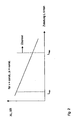
- Fig. 2 shows the course or the dependence of characteristics XL, XR on the payload (payload L rear); This is a vehicle in which the load on the rear axle is increased by the payload.
- L min is the load condition with the lowest possible utilization (driver only, no additional load) and L max is the load condition at which a warning is displayed.
- Fig. 3 serves to illustrate the learning processes of the characteristics XL and XR for the minimum load condition of a vehicle which is loaded substantially at the rear.
- the load distribution characteristics XL t , XR t , XV t and XH t are recorded at various times together with the associated pressure values, stored and statistically evaluated. It is assumed that the condition at partial load or minimum load occurs repeatedly in the operation of a vehicle, which is why the value of the corresponding load distribution characteristic can be recognized by statistical evaluation or conclusion.
- XL t , XR t , XV t and XH t are determined for each ignition run of the vehicle (time between starting the engine and stopping the engine). Additionally to the parameters and the associated tire pressure p i is stored in each case. With the simplifying assumption that the vehicle is also operated unloaded (only driver without additional load) in the case of several ignition runs, a nominal value X nominal can be determined in a particularly simple manner from the values X t via a maximum function.
- Fig. 4 serves to explain the load recognition and the corresponding load distribution characteristics in different Situations and at different tire pressure.
- the applicable boundary conditions are in Fig. 4 called.
- a detection threshold X Schw, Soll provides, which can initially remain uncompensated, since the tire pressure of all wheels corresponds to the target pressure within the required accuracy. If the detection threshold is exceeded, the system generates a warning.
- the detection threshold In the sub-images under b) situations are shown in which one or more wheels has a lower pressure ⁇ p ⁇ 0. Since a wheel with reduced pressure can no longer be utilized as much as a wheel having the desired pressure, the detection threshold must be compensated to X Schw, komp pressure-dependent to lower values. It makes sense to make the adjustment to the lowest pressure per vehicle side. This activates the load warning of too high utilization even at a lower load. In the illustrated cases 2 and 3, the tire pressures of the wheels used to determine X deviate from each other, so that a compensation of X target to X target, komp is required.
- the pressure-dependent compensation of the detection thresholds described above depends on the type of tire used. It has been found that compensation can be carried out with sufficient accuracy, preferably with the aid of vehicle type-dependent constants. This is possible because in a certain type of vehicle usually only certain known types of tires are allowed to operate the vehicle.
- a pressure measurement based method has in principle the disadvantage that the driver only a pressure information can be provided. In how far the tire is used, however, depends not only on the pressure, but also from the current load, which is unknown. The driver must therefore continue to take responsibility for the correct air pressure associated with the load. Although it can often be concluded by means of mostly carried out simultaneously temperature measurement in the TPMS sensor on tire overloads. However, the temperature in the sensor on the rim is subject to numerous disturbing influences. Therefore, these measurements do not reflect with sufficient certainty the temperature load of the tire (at the critical positions).
- a DDS has the disadvantage that the absolute tire pressure is unknown. However, it has the advantage that a rolling circumference change caused by the changed deflection of a tire can be detected. This deflection of the tire is to be regarded as the decisive measure for the utilization of the tire. In practice, it can not be differentiated with DDS whether a change in spring deflection is caused by a change in air pressure or a change in wheel load. The main fault with a tire pressure control via DDS is therefore the load.
- the method according to the invention overcomes both the disadvantages of a known TPMS and also shortcomings of a DDS.
- the method according to the invention is based on the combination of a measurement method based on pressure sensor technology with a method based on observation and evaluation of the wheel speeds, the physical basis of which is based on the dynamic rolling circumferences of the individual tires and on the relative changes of these rolling circumferences with wheel load changes.
- the air pressure is detected exactly. From the wheel rotation behavior, the load of the tire is monitored due to pressure and load variations. This combination offers the opportunity to determine the tire load. The driver can thus largely responsibility for the tire are removed.
- the solution according to the invention also has the advantage that the system can adapt to load variations itself, ie the driver does not have to inform the TPMS that a new pressure setpoint applies depending on the load.
- the method according to the invention makes use of functions and findings in an analogous manner which were obtained in connection with pressure loss detection methods which work on the basis of data from the wheel speed sensors.
- the "normal state”, ie the air pressure correctly set to the current loading state (known via TPMS), can be communicated to the system by the driver, for example by means of a button pressure or, for example, according to the example in FIG Fig. 3 be determined by means of a maximum function without intervention of the driver.
- the rolling circumferences are first determined in a learning phase. Thereafter, after the learning phase, the actual state is compared with the learned state. This comparison provides information about increased jounce and / or load on the tire; the computational procedure is in some ways analogous to the detection of a pressure loss via DDS.
- the decision on the driver's warning of tire overload is made by the combined assessment of current air pressure and deflection.
- the invention includes a method for determining or monitoring tire utilization based on a combination of a direct measuring tire air pressure monitoring system (TPMS) and a system for monitoring wheel rotational behavior and tire rolling circumferences analogous to DDS.
- TPMS direct measuring tire air pressure monitoring system
- the method is preferably carried out in a motor vehicle, in particular a passenger car.
Landscapes
- Engineering & Computer Science (AREA)
- Mechanical Engineering (AREA)
- Transportation (AREA)
- Measuring Fluid Pressure (AREA)
- Regulating Braking Force (AREA)
Applications Claiming Priority (3)
| Application Number | Priority Date | Filing Date | Title |
|---|---|---|---|
| DE10137029 | 2001-07-30 | ||
| DE10137029 | 2001-07-30 | ||
| PCT/EP2002/008478 WO2003016115A1 (de) | 2001-07-30 | 2002-07-30 | Verfahren zur bestimmung der belastung eines fahrzeugreifens |
Publications (2)
| Publication Number | Publication Date |
|---|---|
| EP1414683A1 EP1414683A1 (de) | 2004-05-06 |
| EP1414683B1 true EP1414683B1 (de) | 2011-09-14 |
Family
ID=7693555
Family Applications (1)
| Application Number | Title | Priority Date | Filing Date |
|---|---|---|---|
| EP02760294A Expired - Lifetime EP1414683B1 (de) | 2001-07-30 | 2002-07-30 | Verfahren zur bestimmung der belastung eines fahrzeugreifens |
Country Status (4)
| Country | Link |
|---|---|
| US (1) | US7013721B2 (cg-RX-API-DMAC7.html) |
| EP (1) | EP1414683B1 (cg-RX-API-DMAC7.html) |
| JP (1) | JP2004538210A (cg-RX-API-DMAC7.html) |
| WO (1) | WO2003016115A1 (cg-RX-API-DMAC7.html) |
Families Citing this family (31)
| Publication number | Priority date | Publication date | Assignee | Title |
|---|---|---|---|---|
| DE10302410B4 (de) * | 2002-01-25 | 2016-12-15 | Continental Teves Ag & Co. Ohg | Verfahren und Vorrichtung zur Überwachung eines Reifenluftdrucks |
| WO2004048136A1 (fr) * | 2002-11-28 | 2004-06-10 | Societe De Technologie Michelin | Methode et systeme pour l´extension de la mobilite d´un vehicule |
| AU2003304318A1 (en) * | 2003-07-04 | 2005-01-28 | Pirelli Pneumatici S.P.A. | Method and system for determining a tyre load during the running of a motor vehicle |
| BR0318560A (pt) | 2003-10-24 | 2006-10-10 | Pirelli | método e sistema para determinar um ángulo de desvio de um pneumático, e, método para controlar um veìculo |
| WO2005042281A1 (en) | 2003-10-24 | 2005-05-12 | Pirelli Pneumatici S.P.A. | Method and system for determining a tyre load during the running of a vehicle |
| JP4217197B2 (ja) * | 2004-08-11 | 2009-01-28 | 住友ゴム工業株式会社 | 車両積載条件の判定方法 |
| JP2006084424A (ja) | 2004-09-17 | 2006-03-30 | Sumitomo Rubber Ind Ltd | 荷重配分判定方法 |
| EP1794007B1 (en) | 2004-09-29 | 2008-04-02 | PIRELLI TYRE S.p.A. | Method and system for determining a cornering angle of a tyre during the running of a vehicle |
| US7142102B2 (en) * | 2004-11-07 | 2006-11-28 | Lear Corporation | Weight overload warning system |
| US20080281552A1 (en) * | 2005-11-14 | 2008-11-13 | Continental Teves Ag & Co. Ohg | Method for the Detection of the Loading of a Motor Vehicle |
| FR2898078B1 (fr) * | 2006-03-01 | 2010-07-30 | Michelin Soc Tech | Methode pour determiner l'etat de charge d'un vehicule |
| US7658099B2 (en) | 2006-03-01 | 2010-02-09 | Michelin Recherche Et Technique S.A. | Method for determining the load condition of a vehicle |
| FR2898679B1 (fr) * | 2006-03-16 | 2008-05-30 | Michelin Soc Tech | Procede de determination d'un indicateur des contraintes supportees par un pneumatique de dumper |
| US7714707B2 (en) * | 2007-05-18 | 2010-05-11 | Trw Automotive U.S. Llc | System for measuring life expectancy of a tire condition monitoring system |
| DE102007029870A1 (de) * | 2007-06-28 | 2009-01-02 | Continental Teves Ag & Co. Ohg | Verfahren und Vorrichtung zur Reifenzustandsüberwachung |
| JP4898867B2 (ja) * | 2009-05-11 | 2012-03-21 | 住友ゴム工業株式会社 | 荷重配分判定方法 |
| CN102975581B (zh) * | 2012-12-19 | 2015-03-18 | 中联重机股份有限公司 | 轮胎压力的调整方法、设备和系统 |
| DE102013208553A1 (de) * | 2013-05-08 | 2014-11-13 | Fachhochschule Brandenburg | Verfahren und Vorrichtung zur Erfassung von Zuständen in Reifen |
| DE102013108283A1 (de) * | 2013-08-01 | 2015-02-05 | Scania Cv Ab | Verfahren und System zur Bestimmung eines Druckverhältnisses zwischen einem Sollreifendruck und einem aktuellen Reifendruck für einen Reifen eines Fahrzeugs |
| DE102013108285A1 (de) * | 2013-08-01 | 2015-02-05 | Scania Cv Ab | Verfahren und System zur Bestimmung einer Druckabweichung zwischen einem Sollreifendruck und einem aktuellen Reifendruck für einen Reifen eines Fahrzeugs sowie zur Bestimmung einer Radlast |
| DE102013012993A1 (de) * | 2013-08-02 | 2015-02-05 | Wabco Gmbh | Verfahren zur Ermittlung der Achslast eines Fahrzeugs |
| US9233581B2 (en) | 2013-12-05 | 2016-01-12 | Nissan North America, Inc. | Tire condition advisory system with optimum, advisory and warning states |
| US9056532B1 (en) | 2013-12-05 | 2015-06-16 | Nissan North America, Inc. | Tire condition advisory system |
| TWI579536B (zh) * | 2015-12-28 | 2017-04-21 | 柴方俊 | Method and device for controlling vehicle load by vehicle tire pressure detection |
| CN106626994B (zh) * | 2016-12-24 | 2018-06-29 | 安徽佳通乘用子午线轮胎有限公司 | 一种车辆行驶期间检测轮胎动态垂直载荷的方法及系统 |
| DE102018117579A1 (de) * | 2018-07-20 | 2020-01-23 | Schenck Process Europe Gmbh | Identifikation eines Schienenfahrzeugrades |
| US11774301B2 (en) | 2020-06-16 | 2023-10-03 | The Goodyear Tire & Rubber Company | Tire load estimation system and method |
| DE102021201519A1 (de) | 2021-02-17 | 2022-08-18 | Robert Bosch Gesellschaft mit beschränkter Haftung | Verfahren zur Erfassung und/oder Überwachung eines Reifendrucks eines Anhängers eines Fahrzeuggespanns |
| US12115821B2 (en) | 2021-07-02 | 2024-10-15 | The Goodyear Tire & Rubber Company | Tire pressure monitoring system employing axle cross comparison |
| CN115257249B (zh) * | 2022-08-29 | 2024-07-09 | 浙江联控技术有限公司 | 胎压报警方法、装置、计算机设备及存储介质 |
| US20250153518A1 (en) * | 2023-11-13 | 2025-05-15 | The Goodyear Tire & Rubber Company | Compensating footprint length for inflation pressure changes |
Family Cites Families (17)
| Publication number | Priority date | Publication date | Assignee | Title |
|---|---|---|---|---|
| US4224597A (en) * | 1978-10-27 | 1980-09-23 | Avmar, Incorporated | System for detecting underinflated tire in a rolling vehicle |
| JPH03135810A (ja) | 1989-10-19 | 1991-06-10 | Mitsubishi Motors Corp | タイヤ圧異常検出方法 |
| DE4009540A1 (de) | 1990-03-24 | 1991-09-26 | Teves Gmbh Alfred | Verfahren und system zur reifendruckueberwachung |
| JP3136801B2 (ja) | 1992-10-08 | 2001-02-19 | 株式会社デンソー | タイヤ空気圧検知装置 |
| DE4228894A1 (de) * | 1992-08-29 | 1994-03-03 | Bosch Gmbh Robert | Verfahren und Vorrichtung zur Auswertung von Raddrehzahlsignalen bei einem Kraftfahrzeug |
| US5578984A (en) * | 1993-11-04 | 1996-11-26 | Sumitomo Electric | Tire air pressure reduction detecting method and apparatus |
| JP3300580B2 (ja) | 1994-12-26 | 2002-07-08 | トヨタ自動車株式会社 | タイヤ空気圧推定装置 |
| JP3509330B2 (ja) * | 1995-10-11 | 2004-03-22 | 本田技研工業株式会社 | 車両の車輪減圧判定装置 |
| JP3497304B2 (ja) * | 1995-11-17 | 2004-02-16 | 本田技研工業株式会社 | 車両の制動力制御装置 |
| JP3150893B2 (ja) * | 1996-01-12 | 2001-03-26 | 住友ゴム工業株式会社 | タイヤ識別方法および装置 |
| DE19611364B4 (de) | 1996-03-22 | 2005-10-20 | Daimler Chrysler Ag | Verfahren und Vorrichtung zur Fahrzeugreifenüberwachung |
| DE19613916C2 (de) * | 1996-04-06 | 2001-12-06 | Daimler Chrysler Ag | Verfahren und Vorrichtung zur Reifenüberwachung bei einem Fahrzeug |
| US6321180B1 (en) * | 1996-12-11 | 2001-11-20 | The Goodyear Tire & Rubber Company | Method for characterizing noise level of rotating tire |
| DE19807880A1 (de) | 1998-02-25 | 1999-09-09 | Daimler Chrysler Ag | Verfahren und Vorrichtung zur Überwachung des Reifenluftdrucks von Rädern eines Kraftfahrzeuges |
| DE19917034C1 (de) * | 1999-04-15 | 2000-11-23 | Continental Ag | Verfahren zur Überwachung des Luftdrucks der Reifen eines Kraftfahrzeuges |
| DE10058099A1 (de) * | 2000-11-09 | 2002-05-23 | Continental Teves Ag & Co Ohg | Verfahren und Vorrichtung zum Erkennen oder Abschätzen von Reifenabnutzung |
| JP2003054230A (ja) * | 2001-08-16 | 2003-02-26 | Sumitomo Rubber Ind Ltd | タイヤ空気圧低下検出方法および装置、ならびにタイヤ減圧判定しきい値の選択プログラム |
-
2002
- 2002-07-30 US US10/485,015 patent/US7013721B2/en not_active Expired - Lifetime
- 2002-07-30 EP EP02760294A patent/EP1414683B1/de not_active Expired - Lifetime
- 2002-07-30 WO PCT/EP2002/008478 patent/WO2003016115A1/de not_active Ceased
- 2002-07-30 JP JP2003520642A patent/JP2004538210A/ja active Pending
Non-Patent Citations (1)
| Title |
|---|
| None * |
Also Published As
| Publication number | Publication date |
|---|---|
| JP2004538210A (ja) | 2004-12-24 |
| US20050172709A1 (en) | 2005-08-11 |
| EP1414683A1 (de) | 2004-05-06 |
| WO2003016115A1 (de) | 2003-02-27 |
| US7013721B2 (en) | 2006-03-21 |
Similar Documents
| Publication | Publication Date | Title |
|---|---|---|
| EP1414683A1 (de) | Verfahren zur bestimmung der belastung eines fahrzeugreifens | |
| DE69305374T2 (de) | System und Verfahren zur Bestimmung des Druckverlustes in einem Reifen | |
| EP1480855B1 (de) | Verfahren und vorrichtung zur erkennung abgehobener fahrzeugräder | |
| EP1293362B1 (de) | Verfahren zur Bestimmung des Reifenluftdrucks und der Radlast von Fahrzeugreifen | |
| DE69308011T2 (de) | Verfahren und Vorrichtung zum Erkennen von Reifenfehlern | |
| DE4418070C1 (de) | Verfahren zum Abgleichen der Raddrehzahlen für ein Kraftfahrzeug | |
| WO2018172317A1 (de) | Verfahren, steuereinrichtung und system zum ermitteln einer profiltiefe eines profils eines reifens | |
| DE10144360A1 (de) | Verfahren zum Zuordnen von Reifendruckmessvorrichtungen eines Kraftfahrzeugs zu Radpositionen und Vorrichtung zum Messen des Reifendrucks | |
| EP1615786B1 (de) | Reifendrucküberwachungseinrichtung und verfahren zur reifendrucküberwachung | |
| DE60129225T2 (de) | Auswertungsverfahren der autonomie eines notlaufreifensystems | |
| WO2018202719A1 (de) | Verfahren und vorrichtung zur bestimmung von radlasten an rädern eines fahrzeuges | |
| DE10058099A1 (de) | Verfahren und Vorrichtung zum Erkennen oder Abschätzen von Reifenabnutzung | |
| EP1347903A1 (de) | System und verfahren zur beurteilung eines beladungszustandes eines kraftfahrzeugs | |
| EP1948453B1 (de) | Verfahren zur indirekten reifendrucküberwachung | |
| DE102006033951A1 (de) | Vorrichtung und Verfahren zur Bestimmung einer Radlast eines Reifens eines Kraftwagens | |
| EP1270275B1 (de) | Verfahren und Vorrichtung zur Überwachung von Reifendrücken | |
| DE69715134T2 (de) | Verfahren und Ausrüstung zum Erkennen eines Reifens mit zumindest teilweisem Druckverlust an einem Kraftfahtzeug. | |
| EP1951534B1 (de) | Verfahren zur erkennung der beladung eines kraftfahrzeugs | |
| DE102008014537B4 (de) | Reifenzustandsüberwachungsvorrichtung | |
| DE19712097C1 (de) | System zur Erkennung des Reifenzustands | |
| DE102014226705A1 (de) | System und Verfahren zur Ermittlung eines Reifendruckes eines Reifens eines Rades | |
| EP1240037A1 (de) | Verfahren und vorrichtung zur erkennung eines druckverlustes von reifen in kraftfahrzeugen | |
| EP1403100A1 (de) | Adaptive Reifendruckverlusterkennung | |
| DE10303492A1 (de) | System zur Überwachung des Reifenzustands | |
| EP1765608B1 (de) | Verfahren zur erkennung eines druckverlusts in kraftfahrzeugreifen |
Legal Events
| Date | Code | Title | Description |
|---|---|---|---|
| PUAI | Public reference made under article 153(3) epc to a published international application that has entered the european phase |
Free format text: ORIGINAL CODE: 0009012 |
|
| 17P | Request for examination filed |
Effective date: 20040301 |
|
| AK | Designated contracting states |
Kind code of ref document: A1 Designated state(s): AT BE BG CH CY CZ DE DK EE ES FI FR GB GR IE IT LI LU MC NL PT SE SK TR |
|
| RIN1 | Information on inventor provided before grant (corrected) |
Inventor name: KELLER, LOTHAR Inventor name: SAEGER, PETER Inventor name: KOEBE, ANDREAS Inventor name: GRIESSER, DR. MARTIN |
|
| 17Q | First examination report despatched |
Effective date: 20051222 |
|
| GRAP | Despatch of communication of intention to grant a patent |
Free format text: ORIGINAL CODE: EPIDOSNIGR1 |
|
| RIC1 | Information provided on ipc code assigned before grant |
Ipc: B60C 23/06 20060101ALI20110126BHEP Ipc: B60T 8/172 20060101AFI20110126BHEP |
|
| GRAS | Grant fee paid |
Free format text: ORIGINAL CODE: EPIDOSNIGR3 |
|
| GRAA | (expected) grant |
Free format text: ORIGINAL CODE: 0009210 |
|
| AK | Designated contracting states |
Kind code of ref document: B1 Designated state(s): DE FR IT |
|
| REG | Reference to a national code |
Ref country code: DE Ref legal event code: R096 Ref document number: 50215209 Country of ref document: DE Effective date: 20111117 |
|
| PG25 | Lapsed in a contracting state [announced via postgrant information from national office to epo] |
Ref country code: IT Free format text: LAPSE BECAUSE OF FAILURE TO SUBMIT A TRANSLATION OF THE DESCRIPTION OR TO PAY THE FEE WITHIN THE PRESCRIBED TIME-LIMIT Effective date: 20110914 |
|
| PLBE | No opposition filed within time limit |
Free format text: ORIGINAL CODE: 0009261 |
|
| STAA | Information on the status of an ep patent application or granted ep patent |
Free format text: STATUS: NO OPPOSITION FILED WITHIN TIME LIMIT |
|
| 26N | No opposition filed |
Effective date: 20120615 |
|
| REG | Reference to a national code |
Ref country code: DE Ref legal event code: R097 Ref document number: 50215209 Country of ref document: DE Effective date: 20120615 |
|
| REG | Reference to a national code |
Ref country code: FR Ref legal event code: PLFP Year of fee payment: 14 |
|
| REG | Reference to a national code |
Ref country code: FR Ref legal event code: PLFP Year of fee payment: 15 |
|
| REG | Reference to a national code |
Ref country code: FR Ref legal event code: PLFP Year of fee payment: 16 |
|
| REG | Reference to a national code |
Ref country code: FR Ref legal event code: PLFP Year of fee payment: 17 |
|
| REG | Reference to a national code |
Ref country code: DE Ref legal event code: R084 Ref document number: 50215209 Country of ref document: DE |
|
| PGFP | Annual fee paid to national office [announced via postgrant information from national office to epo] |
Ref country code: FR Payment date: 20210727 Year of fee payment: 20 |
|
| PGFP | Annual fee paid to national office [announced via postgrant information from national office to epo] |
Ref country code: DE Payment date: 20210731 Year of fee payment: 20 |
|
| REG | Reference to a national code |
Ref country code: DE Ref legal event code: R071 Ref document number: 50215209 Country of ref document: DE |