EP1414505B1 - Appareil d'administration comportant un dispositif de dosage - Google Patents
Appareil d'administration comportant un dispositif de dosage Download PDFInfo
- Publication number
- EP1414505B1 EP1414505B1 EP02742641A EP02742641A EP1414505B1 EP 1414505 B1 EP1414505 B1 EP 1414505B1 EP 02742641 A EP02742641 A EP 02742641A EP 02742641 A EP02742641 A EP 02742641A EP 1414505 B1 EP1414505 B1 EP 1414505B1
- Authority
- EP
- European Patent Office
- Prior art keywords
- piston rod
- metering
- movement
- reservoir
- dose setting
- Prior art date
- Legal status (The legal status is an assumption and is not a legal conclusion. Google has not performed a legal analysis and makes no representation as to the accuracy of the status listed.)
- Expired - Lifetime
Links
- 230000007246 mechanism Effects 0.000 claims description 71
- 230000000903 blocking effect Effects 0.000 claims description 36
- 238000002347 injection Methods 0.000 claims description 36
- 239000007924 injection Substances 0.000 claims description 36
- 238000006073 displacement reaction Methods 0.000 claims description 7
- 230000008878 coupling Effects 0.000 claims description 3
- 238000010168 coupling process Methods 0.000 claims description 3
- 238000005859 coupling reaction Methods 0.000 claims description 3
- 238000001802 infusion Methods 0.000 claims description 2
- 239000003708 ampul Substances 0.000 description 14
- 238000009826 distribution Methods 0.000 description 11
- 238000013519 translation Methods 0.000 description 8
- 230000006870 function Effects 0.000 description 7
- 241001417534 Lutjanidae Species 0.000 description 5
- NOESYZHRGYRDHS-UHFFFAOYSA-N insulin Chemical compound N1C(=O)C(NC(=O)C(CCC(N)=O)NC(=O)C(CCC(O)=O)NC(=O)C(C(C)C)NC(=O)C(NC(=O)CN)C(C)CC)CSSCC(C(NC(CO)C(=O)NC(CC(C)C)C(=O)NC(CC=2C=CC(O)=CC=2)C(=O)NC(CCC(N)=O)C(=O)NC(CC(C)C)C(=O)NC(CCC(O)=O)C(=O)NC(CC(N)=O)C(=O)NC(CC=2C=CC(O)=CC=2)C(=O)NC(CSSCC(NC(=O)C(C(C)C)NC(=O)C(CC(C)C)NC(=O)C(CC=2C=CC(O)=CC=2)NC(=O)C(CC(C)C)NC(=O)C(C)NC(=O)C(CCC(O)=O)NC(=O)C(C(C)C)NC(=O)C(CC(C)C)NC(=O)C(CC=2NC=NC=2)NC(=O)C(CO)NC(=O)CNC2=O)C(=O)NCC(=O)NC(CCC(O)=O)C(=O)NC(CCCNC(N)=N)C(=O)NCC(=O)NC(CC=3C=CC=CC=3)C(=O)NC(CC=3C=CC=CC=3)C(=O)NC(CC=3C=CC(O)=CC=3)C(=O)NC(C(C)O)C(=O)N3C(CCC3)C(=O)NC(CCCCN)C(=O)NC(C)C(O)=O)C(=O)NC(CC(N)=O)C(O)=O)=O)NC(=O)C(C(C)CC)NC(=O)C(CO)NC(=O)C(C(C)O)NC(=O)C1CSSCC2NC(=O)C(CC(C)C)NC(=O)C(NC(=O)C(CCC(N)=O)NC(=O)C(CC(N)=O)NC(=O)C(NC(=O)C(N)CC=1C=CC=CC=1)C(C)C)CC1=CN=CN1 NOESYZHRGYRDHS-UHFFFAOYSA-N 0.000 description 4
- 239000011324 bead Substances 0.000 description 3
- 239000002537 cosmetic Substances 0.000 description 3
- 206010012601 diabetes mellitus Diseases 0.000 description 3
- 230000000694 effects Effects 0.000 description 3
- 239000007788 liquid Substances 0.000 description 3
- 238000004519 manufacturing process Methods 0.000 description 3
- 230000004044 response Effects 0.000 description 3
- 230000001225 therapeutic effect Effects 0.000 description 3
- 238000002560 therapeutic procedure Methods 0.000 description 3
- 210000002105 tongue Anatomy 0.000 description 3
- 102000018997 Growth Hormone Human genes 0.000 description 2
- 108010051696 Growth Hormone Proteins 0.000 description 2
- 102000004877 Insulin Human genes 0.000 description 2
- 108090001061 Insulin Proteins 0.000 description 2
- 230000015572 biosynthetic process Effects 0.000 description 2
- 230000006835 compression Effects 0.000 description 2
- 238000007906 compression Methods 0.000 description 2
- 230000009977 dual effect Effects 0.000 description 2
- 239000012530 fluid Substances 0.000 description 2
- 239000000122 growth hormone Substances 0.000 description 2
- 238000003780 insertion Methods 0.000 description 2
- 230000037431 insertion Effects 0.000 description 2
- 229940125396 insulin Drugs 0.000 description 2
- 239000012528 membrane Substances 0.000 description 2
- 238000000034 method Methods 0.000 description 2
- 210000001331 nose Anatomy 0.000 description 2
- 230000001960 triggered effect Effects 0.000 description 2
- 230000009471 action Effects 0.000 description 1
- 230000004323 axial length Effects 0.000 description 1
- 230000004888 barrier function Effects 0.000 description 1
- 230000008901 benefit Effects 0.000 description 1
- 238000006243 chemical reaction Methods 0.000 description 1
- 238000010276 construction Methods 0.000 description 1
- 238000013461 design Methods 0.000 description 1
- 230000002349 favourable effect Effects 0.000 description 1
- 239000005556 hormone Substances 0.000 description 1
- 229940088597 hormone Drugs 0.000 description 1
- 238000007373 indentation Methods 0.000 description 1
- 229940025708 injectable product Drugs 0.000 description 1
- 238000009434 installation Methods 0.000 description 1
- 230000003993 interaction Effects 0.000 description 1
- 239000006199 nebulizer Substances 0.000 description 1
- 230000035764 nutrition Effects 0.000 description 1
- 235000016709 nutrition Nutrition 0.000 description 1
- 238000003825 pressing Methods 0.000 description 1
- 230000037452 priming Effects 0.000 description 1
- 230000008569 process Effects 0.000 description 1
- 230000003716 rejuvenation Effects 0.000 description 1
- 238000012549 training Methods 0.000 description 1
- 230000000007 visual effect Effects 0.000 description 1
Images


Classifications
-
- A—HUMAN NECESSITIES
- A61—MEDICAL OR VETERINARY SCIENCE; HYGIENE
- A61M—DEVICES FOR INTRODUCING MEDIA INTO, OR ONTO, THE BODY; DEVICES FOR TRANSDUCING BODY MEDIA OR FOR TAKING MEDIA FROM THE BODY; DEVICES FOR PRODUCING OR ENDING SLEEP OR STUPOR
- A61M5/00—Devices for bringing media into the body in a subcutaneous, intra-vascular or intramuscular way; Accessories therefor, e.g. filling or cleaning devices, arm-rests
- A61M5/178—Syringes
- A61M5/31—Details
- A61M5/315—Pistons; Piston-rods; Guiding, blocking or restricting the movement of the rod or piston; Appliances on the rod for facilitating dosing ; Dosing mechanisms
- A61M5/31533—Dosing mechanisms, i.e. setting a dose
- A61M5/31545—Setting modes for dosing
- A61M5/31548—Mechanically operated dose setting member
- A61M5/3155—Mechanically operated dose setting member by rotational movement of dose setting member, e.g. during setting or filling of a syringe
- A61M5/31553—Mechanically operated dose setting member by rotational movement of dose setting member, e.g. during setting or filling of a syringe without axial movement of dose setting member
-
- A—HUMAN NECESSITIES
- A61—MEDICAL OR VETERINARY SCIENCE; HYGIENE
- A61M—DEVICES FOR INTRODUCING MEDIA INTO, OR ONTO, THE BODY; DEVICES FOR TRANSDUCING BODY MEDIA OR FOR TAKING MEDIA FROM THE BODY; DEVICES FOR PRODUCING OR ENDING SLEEP OR STUPOR
- A61M5/00—Devices for bringing media into the body in a subcutaneous, intra-vascular or intramuscular way; Accessories therefor, e.g. filling or cleaning devices, arm-rests
- A61M5/178—Syringes
- A61M5/31—Details
- A61M5/315—Pistons; Piston-rods; Guiding, blocking or restricting the movement of the rod or piston; Appliances on the rod for facilitating dosing ; Dosing mechanisms
-
- A—HUMAN NECESSITIES
- A61—MEDICAL OR VETERINARY SCIENCE; HYGIENE
- A61M—DEVICES FOR INTRODUCING MEDIA INTO, OR ONTO, THE BODY; DEVICES FOR TRANSDUCING BODY MEDIA OR FOR TAKING MEDIA FROM THE BODY; DEVICES FOR PRODUCING OR ENDING SLEEP OR STUPOR
- A61M5/00—Devices for bringing media into the body in a subcutaneous, intra-vascular or intramuscular way; Accessories therefor, e.g. filling or cleaning devices, arm-rests
- A61M5/14—Infusion devices, e.g. infusing by gravity; Blood infusion; Accessories therefor
- A61M5/142—Pressure infusion, e.g. using pumps
- A61M5/145—Pressure infusion, e.g. using pumps using pressurised reservoirs, e.g. pressurised by means of pistons
- A61M5/1452—Pressure infusion, e.g. using pumps using pressurised reservoirs, e.g. pressurised by means of pistons pressurised by means of pistons
- A61M5/14566—Pressure infusion, e.g. using pumps using pressurised reservoirs, e.g. pressurised by means of pistons pressurised by means of pistons with a replaceable reservoir for receiving a piston rod of the pump
-
- A—HUMAN NECESSITIES
- A61—MEDICAL OR VETERINARY SCIENCE; HYGIENE
- A61M—DEVICES FOR INTRODUCING MEDIA INTO, OR ONTO, THE BODY; DEVICES FOR TRANSDUCING BODY MEDIA OR FOR TAKING MEDIA FROM THE BODY; DEVICES FOR PRODUCING OR ENDING SLEEP OR STUPOR
- A61M5/00—Devices for bringing media into the body in a subcutaneous, intra-vascular or intramuscular way; Accessories therefor, e.g. filling or cleaning devices, arm-rests
- A61M5/178—Syringes
- A61M5/24—Ampoule syringes, i.e. syringes with needle for use in combination with replaceable ampoules or carpules, e.g. automatic
-
- A—HUMAN NECESSITIES
- A61—MEDICAL OR VETERINARY SCIENCE; HYGIENE
- A61M—DEVICES FOR INTRODUCING MEDIA INTO, OR ONTO, THE BODY; DEVICES FOR TRANSDUCING BODY MEDIA OR FOR TAKING MEDIA FROM THE BODY; DEVICES FOR PRODUCING OR ENDING SLEEP OR STUPOR
- A61M5/00—Devices for bringing media into the body in a subcutaneous, intra-vascular or intramuscular way; Accessories therefor, e.g. filling or cleaning devices, arm-rests
- A61M5/178—Syringes
- A61M5/31—Details
- A61M5/315—Pistons; Piston-rods; Guiding, blocking or restricting the movement of the rod or piston; Appliances on the rod for facilitating dosing ; Dosing mechanisms
- A61M5/31501—Means for blocking or restricting the movement of the rod or piston
-
- A—HUMAN NECESSITIES
- A61—MEDICAL OR VETERINARY SCIENCE; HYGIENE
- A61M—DEVICES FOR INTRODUCING MEDIA INTO, OR ONTO, THE BODY; DEVICES FOR TRANSDUCING BODY MEDIA OR FOR TAKING MEDIA FROM THE BODY; DEVICES FOR PRODUCING OR ENDING SLEEP OR STUPOR
- A61M5/00—Devices for bringing media into the body in a subcutaneous, intra-vascular or intramuscular way; Accessories therefor, e.g. filling or cleaning devices, arm-rests
- A61M5/178—Syringes
- A61M5/31—Details
- A61M5/315—Pistons; Piston-rods; Guiding, blocking or restricting the movement of the rod or piston; Appliances on the rod for facilitating dosing ; Dosing mechanisms
- A61M5/31533—Dosing mechanisms, i.e. setting a dose
- A61M5/31535—Means improving security or handling thereof, e.g. blocking means, means preventing insufficient dosing, means allowing correction of overset dose
-
- A—HUMAN NECESSITIES
- A61—MEDICAL OR VETERINARY SCIENCE; HYGIENE
- A61M—DEVICES FOR INTRODUCING MEDIA INTO, OR ONTO, THE BODY; DEVICES FOR TRANSDUCING BODY MEDIA OR FOR TAKING MEDIA FROM THE BODY; DEVICES FOR PRODUCING OR ENDING SLEEP OR STUPOR
- A61M5/00—Devices for bringing media into the body in a subcutaneous, intra-vascular or intramuscular way; Accessories therefor, e.g. filling or cleaning devices, arm-rests
- A61M5/178—Syringes
- A61M5/31—Details
- A61M5/315—Pistons; Piston-rods; Guiding, blocking or restricting the movement of the rod or piston; Appliances on the rod for facilitating dosing ; Dosing mechanisms
- A61M5/31565—Administration mechanisms, i.e. constructional features, modes of administering a dose
- A61M5/31576—Constructional features or modes of drive mechanisms for piston rods
- A61M5/31578—Constructional features or modes of drive mechanisms for piston rods based on axial translation, i.e. components directly operatively associated and axially moved with plunger rod
- A61M5/3158—Constructional features or modes of drive mechanisms for piston rods based on axial translation, i.e. components directly operatively associated and axially moved with plunger rod performed by axially moving actuator operated by user, e.g. an injection button
Definitions
- the invention relates to administration devices, preferably injection devices, which allow a selection of a product dose to be distributed and are preferably provided for medical, therapeutic, diagnostic, pharmaceutical or cosmetic applications.
- injection devices are injection pens, in particular semidisposable pens.
- An administration device according to the invention may, for example, also be an inhalation device or a device for metered delivery of an orally administered product.
- Delivery devices should be generally handy and therefore small, but on the other hand have the highest possible functionality.
- the first aspect so-called Injekomspens, because of their slim form because of so called, readily meet.
- a key aspect in terms of functionality is the ability to freely select the dose of product to inject with an injection.
- the possibility of product dose selection is particularly advantageous in those applications where a user self-administers the product to be injected, as is common in, for example, diabetes therapy or hormone administration, to name just two preferred examples of use.
- the possibility of flexible product dose selection is accompanied by a corresponding technical effort, which not only increases the price, but also increases the devices concerned.
- a product dose selection type injection pen is described in U.S. Patent No. 4,973,318.
- the pen has a piston rod which is formed by a threaded rod and serves to displace a piston in a product ampule and thereby pour out the product.
- the pen has a front housing sleeve and a rear housing sleeve, which are rotatable relative to one another about a common longitudinal axis. Due to the relative rotation of the two housing sleeves, the product dose is selected.
- the piston rod is threadedly engaged with a threaded nut.
- the threaded nut forms a front portion of a sleeve-shaped metering and actuating element.
- This metering and actuating element projects at a rear end into the rear housing sleeve and is connected secured against rotation with the rear housing sleeve, but displaceable relative to the rear housing sleeve in the longitudinal direction of the piston rod back and forth. If the rear housing sleeve is rotated for the purpose of dose selection, the metering and actuating element is forcibly rotated. However, since the piston rod is connected non-rotatably to the front housing sleeve, the metering and actuating element is moved further out of the rear housing sleeve due to the rotational movement.
- the total length of the assembly of piston rod and metering and actuating element is increased and increased a clear distance between the front end of the metering and actuating element and a stop surface of the housing.
- This clear distance corresponds to the maximum possible stroke, when the metering and actuating element is advanced together with the piston rod for the purpose of product distribution in the direction of a front end of the pen. Because of this fairly simple dosing mechanism corresponds to the stroke of the dispensing movement of each set product dose and is thus variable.
- the piston rod is also designed as a threaded rod and secured against rotation connected to the housing of the pen.
- a dose setting nut is threadedly engaged with the piston rod.
- the piston rod protrudes into sleeve-shaped metering and actuating element.
- the metering and actuation element and the dose setting nut of this pen are separate parts.
- the metering and actuating element is secured against rotation with the dose setting nut, but slidably connected in the longitudinal direction of the piston rod. For this procedure, the dosing and actuating element surrounds the dose setting nut.
- the metering and actuating element is rotated about the longitudinal axis.
- the dose setting nut is turned in this case. Due to the threaded engagement with the piston rod, the linear guide of the dose setting on the housing and the blocking of the piston rod against movement against the feed direction, the dose setting is moved during the rotational movement along the piston rod to the rear and thus deeper into the dosing and actuating element. Between the front end of the dose setting nut and an opposite stop in the feed direction of the housing, there is a clear distance, which corresponds to the commontechnischlegbaren during the dispensing movement of the piston rod and the dose setting mother way and thus the product dose.
- Another object is to design a metering mechanism of a semidisposable pen or other delivery device so that the assembly of the device when replacing a reservoir module is simplified.
- An administering device comprises a housing, a reservoir for a pourable, preferably injectable product and a piston which is slidably received in the reservoir in a direction of advance to a reservoir outlet, so that by displacement of the piston in the feed direction product is distributed through the Reservoirauslass through.
- the reservoir may be formed by a receptacle received by the housing.
- an ampoule can form the reservoir.
- the reservoir can also be formed directly from the housing itself, i. without the interposition of a product container.
- the product is preferably a liquid for medical, therapeutic, diagnostic, pharmaceutical or cosmetic applications.
- the product may be insulin, a growth hormone, or liquid or creamy food.
- the delivery device is preferably used in those applications where a user self-administers the product, as is common in diabetes therapy, for example. However, the use in inpatient and outpatient care by doctors or trained personnel should not be ruled out.
- the delivery device further comprises a piston rod which serves to move the piston in the direction of advance.
- the piston rod may be fixed to the piston, i. constantly, be connected, including an integral formation of piston and piston rod to be understood.
- the piston and the piston rod are designed as separate components, and it presses for the purpose of product distribution, the piston rod with a front end against a rear side of the piston.
- the administration device comprises a metering and drive element with which a metering movement for selecting a product dose and a dispensing movement for distributing the product dose can be carried out relative to the housing.
- the dispensing movement is preferably in the feed direction, and the metering movement is preferably a rotary movement around an axis parallel to the feed direction.
- the metering and drive element is in engagement with the piston rod, which causes entrainment of the piston rod during the metering movement, but does not hinder or at least permit a delivery movement of the metering and drive element relative to the piston rod.
- the engagement of the metering and drive element with the piston rod is positively. If the metering movement is a rotary movement, the connection between the metering and drive element and the piston rod creates a connection secured against rotation about the axis of rotation.
- the administering device comprises a dosage setting member which is engaged with the piston rod and the housing each.
- the dose setting is only movable together with the piston rod in the feed direction and is moved by the metering movement relative to the piston rod against the feed direction.
- the dose setting member is moved by the metering and drive element during its dispensing movement in the feed direction. It performs together with the piston rod itself a dispensing movement, which is transmitted to the piston and leads to product distribution.
- the engagement between the dose setting member and the piston rod is preferably a threaded engagement.
- the piston rod is provided with a thread about the longitudinal axis of the piston rod.
- the engagement can also be formed differently, for example in the manner of a ratchet.
- such a tooth engagement is preferably used to prevent movement of the piston rod against the feed direction.
- the metering and drive element does not act directly on the piston rod, but on the dose setting member during its dispensing movement, as is generally already known from WO 97/17096, an equally long dispensing stroke can be achieved.
- the metering and drive member secured against rotation with the piston rod and the dose setting member is engaged with the housing to obtain a Dosierhub the dose setting against the feed direction, the administering device is slimmer.
- the dosing and drive element no longer has to surround the dosage setting member, as is the case with the known device, in order to effect the dosing stroke of the dose setting nut there.
- the metering and drive element and the dose setting can advantageously be arranged in succession without overlap with respect to the feed direction.
- the metering and drive element can be a very simply shaped part, which merely has to be shaped with respect to the metering in such a way that the rotationally secured, displaceable connection with the piston rod can be produced.
- the invention is particularly advantageous in so-called semi-disposable administration devices, in particular semidisposable injection pens.
- Such delivery devices include a reservoir module that not only includes the reservoir for the product but also holds the piston rod. After emptying the reservoir, the entire reservoir module, including the piston rod, is replaced with a new reservoir module with a filled reservoir.
- a rear part of such a semidisposable delivery device comprises the metering and drive element and usually a counting and display device.
- This generally technically complex and therefore expensive part of the delivery device is designed as a reusable part and can be repeatedly connected to a new reservoir module.
- the reservoir module on the other hand, can be designed as a disposable part, from where the term "semidisposable" comes from.
- the metering and drive device can operate manually, semi-automatically or fully automatically.
- both the rotary metering movement and the translatory discharge movement are carried out manually.
- either the dosing movement or the dispensing movement is carried out manually, and the other movement is effected by motor or by another type of force application, for example by spring force, when the user has triggered the corresponding movement by an actuating handle.
- the metering movement and the delivery movement are effected by means of a motor or by means of another force, for example spring force.
- the delivery device according to the invention is equipped with a manual metering and drive device, which is then referred to as metering and actuating device.
- metering and actuating device As far as therefore of a metering and actuating device is mentioned, it is called the manual execution.
- metering and drive device As far as a metering and drive device is mentioned, this should not be limited to manual, semi-automatic or fully automatic, but it should be encompassed each of the embodiments.
- the term "metering and actuation module" is used in connection with all embodiments of the metering and drive device.
- the metering and drive device may be a metering element that performs the metering movement; and separately have a drive element that performs the dispensing movement.
- the metering movement and dispensing movement are performed by the same body of the metering and drive device, which is therefore hereinafter also referred to as metering and drive element or as metering and actuating element.
- the product is preferably a fluid, more preferably a liquid, for a medical, therapeutic, diagnostic, pharmaceutical or cosmetic application.
- the product may be, for example, insulin, a growth hormone or else a thin to viscous, ripened food.
- the delivery device is preferably used in those applications where a user self-administers the product, as is common in diabetes therapy, for example. However, the use in inpatient and outpatient care by trained personnel should not be excluded.
- the product administration can be carried out in an injection device by means of an injection cannula or, for example, a nozzle for needle-less injections.
- Injection or infusion may in particular be performed subcutaneously or venous, or intramuscularly.
- the selected product dose from the reservoir may be dispensed into a chamber of the inhalation device and atomized by means of a nebulizer for inhalation.
- oral or oesophageal administration to name but a few examples of administration.
- the delivery device is semidisposable.
- the front housing section carries a reservoir module which is disposed of or recirculated after the reservoir has been emptied, and the rear housing section carries a metering and actuation module that is repeatedly used in conjunction with a new reservoir module.
- the reservoir module is also traded separately as a consumption module, it is also separately subject of the invention.
- the metering and actuation module can also be the subject of the invention separately.
- a system of an administration device and at least one reservoir module which can replace the reservoir module of the device for consumption forms an object of the invention.
- the concept of the two-part administering device in a part intended for single use and a part intended for repeated use is advantageous in particular for injection pens, but also for example for inhalation devices or devices for the oral intake of a product or an artificial nutrition.
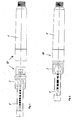
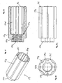
- FIG. 1 shows in a view a reservoir part 1 and a mechanism holder 3 which are connected to one another in order to form the reservoir module 10 shown in FIG.
- a piston rod 4 is further seen, which protrudes at an end facing away from the reservoir part 1 of the mechanism holder 3 in the mechanism holder 3 and of the mechanism holder 3 in a longitudinal axis L of the piston rod 4 facing feed direction to one of the mechanism holder 3 facing away, front end of the reservoir part 1 is slidably mounted.
- the reservoir part 1 is substantially circular in cross-section Hollow cylinder having at its front end a connecting portion for connection to a needle holder for an injection needle.
- the reservoir part 1 is used to receive a reservoir container, which is formed in the embodiment of an ampoule 2, which can be seen in the longitudinal section of Figure 3.
- An outlet at the front end of the ampoule 2 is sealed fluid-tight by a membrane.
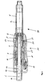
- Figure 3 shows the injection device in its entirety in a longitudinal section.
- a piston is slidably received in the feed direction on the outlet formed at the front end of the ampoule 2.
- product is displaced from the ampoule 2 and distributed through the outlet and the injection needle through.
- the advance of the piston causes the piston rod 4, which presses with its front end against the piston and thereby moves at its own feed the piston in the feed direction.
- the piston rod 4 is held by the mechanism holder 3 so that it can be moved after overcoming a certain resistance in the feed direction, but not against the feed direction.
- the backward movement of the piston rod 4 against the feed direction is prevented by a blocking device 8.
- the blocking device 8 is fixed axially by the mechanism holder 3, i. it is held in the mechanism holder 3 so that it is not movable in and against the feed direction. However, it is rotatably supported by the mechanism holder 3 about the longitudinal axis L.
- the blocking device 8 also generates the resistance that must be overcome for the forward movement.
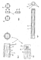
- the blocking device 8 is shown alone in FIG. It is formed by a one-piece ring element, which on the mechanism holder 3 between two mutually spaced spaced shoulders 3b, of an inner shell of the 3 protrude radially inward, about the longitudinal axis L rotatably applied.
- the shoulders 3b form a fixing device for the axial fixing of the blocking device 8.
- the mounting of the blocking device 8 in the mechanism holder 3 is best seen from the representation of the mechanism holder 3 in Figure 5.
- a dose setting member 9 is further included in the mechanism holder 3.
- the dose setting member 9 is formed as a threaded nut and is in threaded engagement with an external thread of the piston rod 4.
- the dose setting member 9 is secured against rotation by the mechanism holder 3, but guided axially linearly movable in and against the feed direction.
- the piston rod 4 and dose setting member 9 form a spindle drive to select the product dose to be administered.
- the ampoule holder 1 and the mechanism holder 3 are rotationally and non-displaceably connected to one another and together form the reservoir module 10 of the injection device, this reservoir module 10 comprising the piston rod 4 and the dosage setting member 9 held by the mechanism holder 3 by means of the blocking device 8.
- the ampoule holder 1 and the mechanism holder 3 together form a front housing portion of the injection device. With this front housing section 1, 3, a rear housing portion 11 is positively connected.
- the rear housing portion 11 forms the carrier of a metering and actuating element 12 and together with the same and parts of a locking device and other parts of a metering and actuation module 30 of the injection device.
- a metering and actuation device comprises the other components for the selection of the product dose and the actuation of the injection device.
- it comprises the metering and actuating element 12.
- the metering and actuating device comprises a counting and display device 17 for counting and visual display of the selected Product dosage.
- the counting and display device 17 makes the dosing and actuation module 30 to a high-quality and therefore high-priced part of the injection device. While the comparatively inexpensive reservoir module 10 is designed as a disposable module, the metering and actuation module 30 is intended for repeated use with ever new reservoir modules 10.
- the metering and actuating element 12 is rotatable about the longitudinal axis L and further supported in the feed direction along the longitudinal axis L of the rear housing portion 11.
- the metering and actuating element 12 is hollow cylindrical and surrounds the piston rod 4 with a front section. A rear section of the metering and actuating element 12 projects beyond a rear end of the housing section 11.
- a rod-shaped Dosiermit matter 13 is inserted from the rear against a radially inwardly projecting shoulder of the metering and actuating element 12.
- a closure 14 is inserted against the Dosiermitnitrogen 13 in the metering and actuating element 12.
- the Dosiermit demanding 13 is axially fixed between the radially projecting shoulder of the metering and actuating element 12 and the closure 14 relative to the metering and actuating element 12.
- the Dosiermit demanding 13 is also connected against rotation with the metering and actuating element 12.
- the Dosiermit facultative 13 projects for the purpose of dosage from behind into the hollow piston rod 4 inside.
- the piston rod 4 has a connecting portion 4a (FIG.
- the connecting portion 4a is formed as a linear guide for the Dosiermitcret 13.
- a return device 16 biases the dosing and actuating element 12 elastically against the feed direction in the starting position shown in Figures 3 and 4.
- In the initial position can be made by rotation of the metering and actuating element 12 about the longitudinal axis L, the dosage.
- the distribution of the selected product dose can be effected from the initial position by axial displacement of the metering and actuating element 12.
- the restoring device 16 is formed by a helical spring acting as a compression spring, which is received in an annular gap around the metering and actuating element 12 and between a radially inwardly projecting shoulder of the housing portion 11 and a radially outwardly projecting radially outwardly shoulder of the metering and actuating element 12 is axially supported.
- the blocking device 8 fulfills a dual function. On the one hand, with its blocking elements 8a, it ensures that the piston rod 4 can not be moved back counter to the feed direction relative to the mechanism holder 3, and thus in particular relative to the piston received in the ampoule 2. In its dual function, the blocking device 8 further prevents the brake as a forward movement of the piston rod 4 in the dosing, in which the dose setting 9 is moved axially against the feed direction to the dosing and actuating element 12.
- the dose setting member 9 In the initial position shown in FIGS. 3 and 4, prior to metering, the dose setting member 9 lies in the direction of advance against an ejection stop 3c formed by the mechanism holder 3 (FIG. 5).
- the piston rod 4 is in permanent contact with the piston.
- the dose setting member 9 is moved by the threaded engagement with the piston rod 4 and the linear guide through the mechanism holder 3 from the Aus thoroughlyanschlag 3 c away on the metering and actuating element 12.
- a clear distance between a rear abutment surface of the dose setting member 9 and a front abutment surface of the metering and actuating element 12 is reduced, on the other hand however, the clearance between a front abutment surface of the dose setting member 9 and the delivery stopper 3c is increased.
- the latter distance between the discharge stopper 3c and the dosage setting member 9 is the path length by which the dose setting member 9 is moved in the course of the delivery movement of the metering and actuating element 12 and also the piston rod 4 in the feed direction because of the threaded engagement.
- the discharge stopper 3c forms a front translational stop.
- the piston rod 4 presses against the piston with its front end, which is formed by a plunger body which is not movably connected to the piston rod 4 and against the feed direction, and presses the piston in the direction of advance toward the outlet of the ampoule 2.
- the longitudinal axis L forms the rotation and translation axes of the movements that are carried out for the purpose of metering and product dispensing.
- the distance between the dose setting member 9 and the metering and actuation element 12 before the metering operation when the dose setting member 9 abuts against the delivery stopper 3c corresponds to the maximum product dose which can be selected and distributed in the course of a discharge.
- the lifting movement of the metering and actuating element 12 is the same length for each distribution. It is set by the dosage only the distance of the dose setting 9 of the Aus frequentlyanschlag 3c and thus in the course of the distribution of the dosing and actuating element 12 and the dose setting 9 together safelylegbare path length.
- the blocking device 8 for braking engagement has two brake elements 8b which, like the locking elements 8a, are each formed by an elastically yielding snapper.
- the blocking device 8 is formed in the embodiment of a single ring element, of which four elastic on one end face Protrude snappers axially. The snapper are distributed uniformly over the circumference of the ring element. Two opposing snapper form the locking elements 8a and the two other, also oppositely arranged snapper form the brake elements 8b.
- the piston rod 4 accordingly has two retraction locking devices 6 formed on opposite sides on the outer jacket and extending in the longitudinal direction of the piston rod 4 and two advancing brake devices 7 extending on likewise opposite sides in the longitudinal direction of the piston rod 4.
- the thread of the piston rod 4 for threaded engagement with the dose setting member 9 is formed by four remaining threaded portions 5 which extend over almost the entire length of the piston rod 4.
- the remindzusperr noiseen 6 and the feed braking devices 7 are each formed by a row of teeth. While the teeth of remindzugsperr Hughes 6 but are swept in the feed direction saw teeth with rearwardly facing, transverse to the feed direction extending locking surfaces are formed, the two rows of teeth that form the feed brake means 7, not facing forward locking surfaces with a comparable barrier effect.
- the teeth of the advancing brake devices 7 each have a softer tooth profile than the retraction locking devices 6.
- the braking engagement of the blocking device 8 with the feed brake means 7 of the piston rod 4 is not intended to prevent a feed movement of the piston rod 4, but only complicate to ensure that the piston rod 4 is not moved in the feed direction in the feed direction.
- the teeth of the advancing brake devices 7 are at their front sides and the brake elements 8b are formed at their rear sides, which contact the front sides of the teeth of the advancing brake device 7, so that to overcome the braking intervention, a threshold force must be overcome, which is not reached in the dosage. This threshold force is greater than the force required to move the teeth of the retraction locking devices 6 over the locking elements 8a in the feed direction.
- the threshold force is at least twice as large as the initial frictional force between the remindzugsausperr wornen 6 and the locking elements 8a.
- the frictional force between the latter also increases gradually only during the course of the advancing movement between two successive interlocking interventions.
- the threshold force of the braking engagement must be applied in each locking engagement immediately at the beginning of the feed movement of a locking intervention in the next following.
- the threshold force should not be so great that it is perceived by the user in the distribution as disturbing.
- An undesired advancing movement of the piston rod in response to the movement of the dosage setting member 9 in the dose selection can in principle also be effected solely by the blocking engagement of the blocking device 8. However, such a movement is more reliably prevented because of the braking engagement than by the locking intervention alone.
- connection between the reservoir module 10 and the metering and actuation module 30 is form-fitting.
- the front housing section 1, 3 and the rear housing section 11 are axially linearly guided directly adjacent to each other to prevent relative rotation in the connection and in the connected state.
- the axial guides 3d of the mechanical holder 3, which form the linear guide with one or more corresponding engagement elements of the rear housing section 11, can be easily recognized.
- the axial guides 3d are formed by guide surfaces on guide ribs; they could also be formed by guide surfaces in axially extending recesses. In this way, axial guide channels are obtained.
- the guide ribs are axially tapered so that leading insertion funnels for the one or more engagement elements of the rear housing section 11 are formed in the guide channels. For even better centering of the housing sections 1, 3 and 11 at the beginning of the connection, the guide ribs are also in the radial direction rejuvenated.
- the one or more engagement elements of the rear housing section 11 is or are preferably formed like the axial sections 3d on the mantle counter surface, ie the inner lateral surface, of the rear housing section 11.
- the locking engagement consists between a female, first locking element 3a of the mechanism holder 3 ( Figure 5) and a locking ring 20 which is connected to the rear housing portion 11 radially movable, but not axially movable.
- the locking ring 20 forms a male, second locking element 21 engaging radially directly in the first locking element 3a.
- Figures 3 and 4 show the locking element 21 in locking engagement with the locking element 3a.
- the locking element 3 a is formed by an annular web and a groove, which rotate on the outer jacket of the mechanism holder 3.
- the ring land forms a rear side wall of the groove.
- the second locking element 21 is formed by a cam, which protrudes radially inwardly from the inner shell of the locking ring 20 and is pressed in locking engagement by a restoring device 24 radially inwardly over an inner circumferential surface of the rear housing portion 11 projecting into the female locking element 3a.
- the locking ring 20 is supported in its entirety in the radial direction by means of the restoring device 24 on an inner shell surface formed by the housing section 11, so that the restoring device 24 presses against the outer shell of the locking ring 20 approximately in the radial extension of the locking element 21.
- the locking ring 20 surrounds the mechanism holder 3 and is in its entirety against the restoring force of the return means 24 radially movable back and forth, so that the second locking element 21 in and out of the locking engagement with the first Locking element 3a can be brought.
- the rear housing portion 11 forms a tight sliding guide for the radial movement of the locking ring 20.
- At its locking element 21 radially opposite side of the locking ring 20 forms a release button 22 for the user.
- a guide cam protrudes radially from the outer circumferential surface of the locking ring 20 facing away from the locking element 21.
- the release position therefore coincides with the foremost displacement position, which occupies the metering and actuating element 12 when it in turn abuts against the Aus featureanschlag 3c of the mechanism holder 3 in the course of its Aus wellzi to the dose setting 9 and the dose setting.
- a mechanical stop for the metering and actuation element 12 is formed by a stop element 31 of the metering and actuation device.
- a reset holder ring which serves to reset the display 17, the stop element 31.
- the stop of the metering and actuating element 12 against this stop element 31 defines the release position of the metering and actuating element 12 in this case, which defined by the stop element 31 release position corresponds to that which is defined by the abutment of the dose setting 9 at the Aus commonlyanschlag 3c.
- FIG 8 shows the locking lock 25. It is formed integrally in the embodiment of a locking slide.
- the locking catch 25 has a plate-shaped main body, which extends axially in the assembled state, as shown for example in Figure 4. At one end of the main body protrudes a web 26 at right angles. In the mounted state, the web 26 extends radially up to against the metering and actuating element 12.
- the web 26 serves to fasten the locking lock 25 on the metering and actuating element 12, which has two axially spaced formed on an outer circumferential surface ring lands, the driver 15a and 15b form.
- the front driver 15b simultaneously forms the support shoulder for the return device 16.
- the locking catch 25 protrudes with its web 26 and is axially enclosed on both sides by the two drivers 15a and 15b.
- the main body of the lock catch 25 is provided with an axial recess 27 open to the front end of the lock catch 25.
- axially extending locking tongues 28 are formed.
- the two locking cams 23 of the locking ring 20 are arranged so that each one of these locking cam 23 presses against one of the locking tongues 28, as long as the metering and actuating element 12 does not occupy the release position.
- the return device 24 for the locking element 21 extends during the axial movement of the locking catch 25.
- Einschausnaturalept 29 are further formed, which define the release position of the metering and actuating element 12.
- Per locking cam 23 each have a Einschreibausnaturalung 29 is provided.
- the position of Einschreibausnaturalept 29 is chosen so that they only come into overlap with the locking cam 23 and thereby allow retraction of the locking cam 23 when the metering and actuating element 12 has been advanced to its release position.
- the locking lock could also be made in one piece with the metering and actuating element 12.
- the training as a separate part offers advantages in terms of manufacturing, assembly and the interaction of the metering and actuating element 12 with the piston rod 4.
- the locking catch 25 at its from the locking element 21 opposite outer side is supported on an inner circumferential surface of the housing 11. In this way, the stability of the lock for the locking engagement is increased.
- the housing 11 forms an axial guide for the locking catch 25th
- the metering and actuation module 30 and the new reservoir module 10 are aligned axially with respect to each other so that their two longitudinal axes are aligned with each other. Subsequently, the reservoir module 10 is inserted with its rear end into the forwardly open housing 11 of the metering and actuation module 30.
- the housing section 1, 3 and the housing portion 11 centered at the tapered ends of the guide ribs 3d of the mechanism holder 3. While sliding the two housing sections are axially linearly guided together in a predetermined by the linear guide rotational angular position, until the housing sections 1, 3 and 11 a Occupy the connection end position in which the locking engagement of the locking elements 3a and 21 can be made or self-adjusting.
- the metering and actuating element 12 is locked in predetermined rotational angle positions relative to the rear housing portion 11.
- the linear guide of the housing sections 1, 3 and 11 and the rotational locking position of the metering and actuating element 12 are coordinated so that the rotationally secured engagement of the metering and actuating element 12 with the piston rod 4 in each locking position of the metering and actuating element 12 and each rotational angular position, in which the housing sections 1, 3 and 11 are linearly guided together, is produced.
- the locking element 21 is held by the locking catch 25 in its radially innermost position.
- the metering and actuation module 30 and the reservoir module 10 can not be pushed together into the final connection position and therefore not connected to each other, since the annular web formed on the outer shell of the mechanism holder 3, which mit stipulate the first locking element 3a, before against the second locking element 21 comes to rest on stop.
- the annular land can be reduced to a short tangential radial projection, if it is ensured that the housing sections 1, 3 and 11 can be assembled only in the rotational angular position, in which such a projection and the second locking member 21 to lie in axial alignment come.
- the annular ridge or radial projection could be the first Locking element 3a also form alone, since it is the essential function of the first locking element 3a, to allow the establishment of the connection between the reservoir module 10 and the metering and actuation module 30 only when the metering and actuating element 12 assumes its release position.
- the metering and actuation element 12 would ensure that the dose setting member 9 is in its zeroing position when it is connected to the delivery stop 3c of the mechanism holder when establishing the connection between the reservoir module 10 and the metering and actuation module 30 3 abuts.
- the user presses the metering and actuating member 12 axially relative to the rear housing portion 11 to the release position.
- the locking cams 23 can be moved into the engagement receptacles 29 of the locking catch 25.
- the user therefore not only presses the metering and actuating element 12 to at least in the release position, but at the same time by means of the release button 22, the first locking element 20 from the locking engagement.
- the reservoir module 10 can now be moved axially over the annular web of the first locking element 3 a and further inserted into the rear housing section 11. The user can release the unlock button 22.
- the reservoir module 10 and the metering and actuation module 30 are now connected to each other in a defined manner with respect to the position of the dose setting member 9 and the piston rod 4. If the dosage setting member 9 has still shown a clear distance from the Aus thoroughlyanschlag 3c before making the locking engagement, this distance is eliminated due to the action of the metering and actuating element 12 required for establishing the connection. An accompanying one Product release can be tolerated and may even be desirable for the purpose of priming the injection needle.
- the counting and display device 17 is preferably zeroed.
- the dosage is effected by rotation of the metering and actuating element 12 about the longitudinal axis L and relative to the housing portion 11. Since the Dosiermit supportive 13 is connected against rotation with the metering and actuating element 12 and in turn engages against rotation in the piston rod 4, takes the dosing and Actuator 12 in the rotary metering the piston rod 4 with. Due to the threaded engagement between the piston rod 4 and the dose setting member 9 and the linear guide of dose setting 9 through the mechanism holder 3, the dose setting 9 performs a predetermined by the thread pitch of the mutual thread engagement, axial translational dosing in the direction of the dosing and actuating element 12. The metering and actuating element 12 forms a rear translation stop 12c, which limits the translational metering movement of the dose setting member 9 and thereby defines the maximum adjustable delivery stroke.
- Counting and indicating device 17 counts the dose units corresponding to the rotational angle position of metering and actuating element 12 and visually displays them.
- the dosing process is completed.
- the distribution of the selected product dose is effected by means of the discharge movement of the dosing and actuating element 12 pointing in the direction of advance of the piston.
- the dosing and actuating element 12 abuts against the dosage setting member 9 and takes it with him.
- the dose setting member 9 abuts in the course of Aus.rois against the Aus.anschlag 3 c of the mechanism holder 3, the Aus thoroughlyroisen the metering and actuating element 12 and the Product distribution finished.
- the return device 16 counter is preferably moved by the return device 16 counter to the feed direction back into a new starting position for a new dosage and product distribution.
- the counting and display device 17 is preferably coupled to the metering and actuating element 12 so that it has meanwhile been returned to zero. If appropriate, it has means for counting and displaying the total amount of product already distributed and thus the remaining amount of product in the ampoule 2.
- the metering and actuation element 12 In order to release the reservoir module 10 from the metering and actuation module 30, the metering and actuation element 12 is moved into the release position, i. until it stops against the dosage setting 9, moved forward. In this position, the user can release the locking engagement again by pressing the unlocking button 22 and disconnect the reservoir module 10 from the metering and actuation module 30.
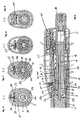
- FIGS. 9 to 13 show in a longitudinal section and four cross sections a second embodiment of an injection device.
- the injection apparatus of the second embodiment is similar to that of the first embodiment with respect to the lock and the lock-lock 25 so that reference is made to the relevant description of the first embodiment.
- the lock-up lock 25 of the second embodiment is identical to that of the first embodiment in all functional details. The same applies to the locking elements 3a and 21st
- the injection device of the second embodiment differs from the first embodiment by the engagement and the movement of the components involved in the dosage. Furthermore, beyond the functions of the mechanism holder of the first embodiment, the mechanism holder in particular fulfills the function of positioning the dose setting member in discrete rotational angular positions which are variable relative to the mechanism holder for the purpose of metering.
- the blocking device of the second embodiment is made simpler than that of the first embodiment. In the following, only the differences compared to the first embodiment will be described in the first place, for components that are identical in their basic function to the same components of the first embodiment, but in details, 30iger numbers with the same final digit or exactly the same reference numerals in the first embodiment. As far as the second embodiment, no comments are made, the corresponding statements to apply to the first embodiment.
- the relative to the rear housing portion 11 axially linearly movable and rotatable about the longitudinal axis L metering and actuating element 32 is connected against rotation with the dose setting 39.
- the metering and actuating element 32 and the dose setting member 39 are movable relative to each other and relative to the housing sections 1, 3 and 11 in and against the feed direction.
- the piston rod 4 is held against rotation by the mechanism holder 3.
- the functionally identical with the first embodiment stuntzugsperr worn 6 prevents in cooperation with locking elements integrally formed on the mechanism holder 3 blocking device 38, a movement of the piston rod 4 against the feed direction, but allows movement in the feed direction.
- the metering and actuating element 32 forms a sliding guide for the piston rod 4.
- the blocking elements form at the same time the retraction lock and the rotation lock for the piston rod 4.
- the dosage setting member 39 thus performs a rotary dosing movement and a translatory dosing movement relative to the front housing section during dosing, while the piston rod 4 is stationary.
- the piston rod 4 is advanced by the path length which corresponds to the set by the dosage clear distance between a stop surface of the dose setting 39 and the delivery stop 3c of the mechanism holder 3.
- the translational metering movement of the dosage setting member 39 is limited against the advancing direction by a rear translation stop 11c, which the rear housing portion 11 itself forms directly.
- the longitudinal axis L forms the axis of rotation and translation of the components involved in metering and product dispensing.
- the front housing section 1, 3 forms a sliding guide for the dosage setting member 39.
- an inner circumferential surface of the mechanical holder 3 and an outer circumferential surface of the dose setting member 39 are in sliding contact with each other.
- the metering and actuating element 32 is engaged with an inner circumferential surface of the dose setting member 39 in engagement with the non-rotational connection between the dosage setting member 39 and the metering and actuating element 32 to form.
- the piston rod 4 via the retraction locking device 6 also has no own braking device.
- the front sides of the saw teeth of the retraction locking device 6 rather alone form the braking device.
- the piston rod 4 of the second embodiment can be replaced by the piston rod of the first embodiment. Accordingly, in this case by the mechanism holder 3 of the second embodiment, at least one braking element, preferably both brake elements of the first embodiment would be formed.
- Figures 14 to 16 show the mechanism holder 3 of the second embodiment in a perspective view, a side view and in the registered in side view cross-section A-A.
- the mechanism holder 3 is designed as a one-piece sleeve part as in the first embodiment, preferably as a plastic injection molded part. It has on the outer jacket of a front sleeve portion on a bead 3e. The front sleeve portion is inserted into the reservoir part 1 and by means of the bead 3e at least for the user inextricably locked to the reservoir part 1.
- the locking element 3a is formed on a central sleeve portion of the mechanism holder 3 as in the first embodiment.
- the axial guides 3d are formed by guide ribs which project radially on the outer circumference of the rear sleeve section. More specifically, the axial guide is formed by the axially extending, straight side walls of these guide ribs, so that, as in the first embodiment, axial guide channels are obtained.
- the guide ribs protrude from the Middle sleeve portion of like fingers to the rear end of the mechanism holder 3, where they taper axially tapered.
- the axial guide 3d serves to guide the linear movement of the rear housing section 11 when the reservoir module 10 is connected to the metering and actuation module 30.
- the amount of an inner circumferential surface of the rear housing section 11 is corresponding and in shape adapted engagement elements 11 d radially inwardly from.
- each of the axial guides 3d protrudes an engagement member 11 d and is linearly guided by the axial guide 3d, when the front housing section 1, 3 and the rear housing section 11 are pushed into each other for connecting. In this way, it is ensured that between the front housing portion 1, 3 and the rear housing portion 11, no relative rotation can take place when in the course of connecting the rotationally secured engagement between the metering and actuating element 32 and the dose setting member 39 is made.
- the guide ribs tapering axially tapered at their rear ends and the guide channels are so widened to insertion funnels, a centering between the front housing portion 1, 3 and the rear housing portion 11 is facilitated for the purpose of connecting.
- the guide ribs taper at their ends also radially to the lateral surface of the mechanism holder 3, whereby the centering of the housing sections 1, 3 and 11 in a predetermined by the axial guide 3d rotational angular position relative to each other even easier.
- the dose setting member 39 is fixed relative to its rotational angular position relative to the front housing portion 1, 3, said fixation is solvable allow the required for the dosage rotation of the dose setting 39. Therefore, on the one hand to allow the metering movement of the dose setting 39, but on the other hand, an undesirable metering movement by establishing the connection between the front Housing section 1, 3 and the rear housing portion 11 to prevent the dosage setting member 39 is fixed by the mechanism holder 3 by means of a releasable latching connection in discrete rotational angular positions.
- Figures 17 to 20 show the dose setting member 39 in individual representations.
- a plurality of latching receptacles 39g are formed on the outer circumferential surface of the dosage setting member 39 distributed over the circumference at a regular pitch.
- Each of the locking receptacles 39g is formed by a straight, axially extending groove with a rounded contour extending in cross-section.
- the mechanism holder 3 is provided with two latching noses 3g (FIGS. 15 and 16).
- the two locking lugs 3g protrude in the rear sleeve portion of the mechanism holder 3 from an inner circumferential surface of the mechanism holder 3 radially inwardly. They are arranged diametrically opposite each other.
- the locking engagement is designed so that the rotational angle fixation of dose setting 39 is so stable that when connecting the front housing portion 1, 3 with the rear housing portion 11 no unwanted dosing of the dose setting 39 can take place, if the rotational coupling of the dosing and actuating element 32 is made with the metering and actuating element 32.
- the latching connection between the mechanism holder 3 and the dosage setting member 39 gives as an advantageous side effect a tactile signal during dosing.
- the rear sleeve portion of the mechanism holder 3 is cut out in the respective jacket region, so that the spring element 3f is obtained as a circumferentially extending ring segment which is exposed axially on both sides.
- axial guides 39d for non-rotatable engagement of the dose setting member 39 with the metering and actuation element 32.
- the metering and actuation element 32 is provided with at least one engagement element to provide axial linear guidance, i. the rotation, to get between the metering and actuating element 32 and the dose setting 39.
- the axial guides 39d are again guide channels, which are formed by a plurality of axially extending guide ribs. Each of the guide ribs is axially and radially tapered at its rear end facing the metering and actuation element 32 in order to facilitate the centering between the metering and actuation element 32 and the dose setting element 39 in the production of the rotationally secure engagement.
- the axial linear guide of dose setting 39 and metering and actuating element 32 thus the same construction as for the axial linear guide of the housing sections 1, 3 and 11 is used.
- 39 rotational stops 39h are formed at a front end of the dose setting member.
- the rotational stops 39h in the front end position occupied by the dosage setting member 39 immediately after a product dispensing or before a dose selection are engaged with rotational counterstops 3h formed on the mechanism holder 3 (FIG. 16).
- the rotational stops 39h protrude axially from a front end face of the dosage setting member 39, and the rotational counter stops 3h project from an axially facing end face of the Mechanism holder 3, which forms the Auf commonlyanschlag 3c, the rotational stops 39h axially opposite.
- the engagement between the rotational stops 39h and the rotational counter-stoppers 3h is such as to permit rotational metering movement in a rotational direction which causes a translational metering movement of the dose setting member 39 away from the delivery stopper 3c, but rotational metering movement in the reverse direction of rotation in the forward axial end position prevented.
- the height, i. the axial length, all of the rotational stops 3h, 39h, 11i and 39i is matched to the pitch of the engaged metering threads of the piston rod 4 and the dose setting member 39.
- the rotational stops are axially so short that the rotary metering movement is not hindered, by which the dose setting member 39 is moved away from the respective translation stop 3 c or 11 c.
- the dosage setting member 39 is screwed onto the piston rod 4 up to a predetermined axial position, as can be seen in FIG. Subsequently, the Piston rod 4 is introduced with the screwed dose setting 39 from behind into the mechanism holder 3 until the blocking device 38 comes into locking engagement with the remindzugsssperr adopted 6 of the piston rod 4 and further the rotationally secured engagement between the rotational stops 39h of the dose setting 39 and the VerFD brieflyanelle 3h of the mechanism holder 3 is made ,
- the dosage setting member 39 is axially linearly guided in a rotational locking position by the locking engagement between the locking lugs 3g and the locking receptacles 39g of the mechanism holder 3 until the dose setting member 39 abuts the Aus thoroughlyanschlag 3c of the mechanism holder 3. In this front end position of the dose setting member 39 relative to the mechanism holder 3, the rotation-proof engagement between the rotation stops 3h and 39h is simultaneously already established.
- the rear housing portion 11 of the fully assembled metering and actuation module 30 is pushed onto the mechanism holder 3, wherein the mechanism holder 3 and the rear housing portion 11 due to the axial guides 3d and the engagement elements 11 d of the rear housing portion 11 can center each other and be guided linearly to each other after centering due to the guiding engagement.
- the dosing and actuating element 32 passes into the rotationally secured engagement with the dose setting member 39, wherein here also by a the axial guides 3d and engagement elements 11 d corresponding linear guide can first take place a certain centering.
- the metering and actuating element 32 is in discrete Drehwinkelrastpositionen with the rear housing portion in a latching engagement and is guided axially linearly in the latching engagement, ie in the respective rotational locking position.
- the rotation angle difference between two consecutive Angular locking positions corresponds to a dose unit.
- the linear guide between the mechanism holder 3 and the rear housing section 11 on the one hand and the discrete rotational angular positions of the dose setting member 39 relative to the mechanism holder 3 (locking lugs 3g and latching receptacles 39g) and the Drehwinkelrastpositionen the metering and actuating element 32 relative to the rear housing portion 11 on the other hand are so that the linear displacement of the two housing sections 1, 3 and 11 always takes place in such a rotational angle position that the dosage setting member 39 and the metering and actuating element 32 are also aligned relative to one another for their rotationally engaged engagement, so that during the connection of the reservoir module 10 With the metering and actuation module 30, there is no relative rotation between the components involved in the metering.
- anti-rotation devices can be provided which prevent undesired reaction movements of the piston rod 4 in the two axial end positions of the dose setting member 9 of the first embodiment.
- Figure 21 shows the two anti-rotation, which are shaped in the same way as the anti-rotation of the second embodiment.
- the rotational counter-abutments formed on the housing sections 1, 3, and 11 in the first embodiment are formed by the blocking device 8 and the metering and actuating element 12, respectively.
- a plurality of rotational stops 8h are formed, which project axially onto the dose setting member 9.
- the second rotation stopper pair is formed between the dose setting member 9 and the rear translation stopper 12c.
- the dose setting member 9 is provided on its rear side with torsion stops 9i as in the second embodiment, which engage in the rear axial end position of the dose setting member 9 into engagement with the rotational stops 12i. In the rear axial end position of the dose setting 9, only the rotary metering movement is allowed by the rear Verdichtanschlagschreib 9i / 12i, which causes a translational metering movement of dose setting 9 in the feed direction.
Claims (13)
- Dispositif d'administration comportant un dispositif de dosage, le dispositif d'administration comprenant :a) un boîtier (1, 3, 11) équipé d'un réservoir (2) pour un produit pouvant être évacué,b) un piston qui peut être déplacé dans le réservoir (2) en direction d'une sortie du réservoir pour évacuer le produit,c) une tige du piston (4),d) un élément d'entraînement (12) avec lequel un mouvement de rotation peut être exécuté par rapport au boîtier (1, 3, 11),
caractérisé en ce qued1) l'élément d'entraînement est un élément de dosage et d'entraînement (12), avec lequel un mouvement de dosage sous la forme d'un mouvement de rotation afin de choisir une dose de produit, et un mouvement d'évacuation sous la forme d'un mouvement linéaire pour évacuer la dose de produit peuvent être réalisés par rapport au boîtier (1, 3, 11), et qui est engagé sur la tige du piston (4) de manière à provoquer un entraînement de la tige du piston (4) lors du mouvement de rotation, mais qui autorise le mouvement linéaire d'évacuation de l'élément de dosage et d'entraînement (12) par rapport à la tige du piston (4),e) et par un organe de réglage de la dose (9), qui est déplacé dans la direction d'avancement par l'élément de dosage et d'entraînement (12) lors du mouvement d'évacuation et qui est engagé sur la tige du piston (4) et dans le boîtier (1, 3, 11) de manière à ne pouvoir être déplacé dans la direction d'avancement qu'avec la tige du piston (4) et qui est déplacé par le mouvement de dosage par rapport à la tige du piston (4) dans le sens opposé à la direction d'avancement. - Dispositif d'administration selon l'une des revendications précédentes, caractérisé en ce que l'organe de réglage de la dose (9) et l'élément de dosage et d'entraînement (12) sont agencés l'un derrière l'autre par rapport à la direction d'avancement, sans se chevaucher.
- Dispositif d'administration selon l'une des revendications précédentes, caractérisé en ce qu'un dispositif de blocage (8) est prévu, qui est engagé sur la tige du piston (4), afin d'empêcher un mouvement de la tige du piston (4) dans le sens opposé à la direction d'avancement.
- Dispositif d'administration selon l'une des revendications précédentes, caractérisé en ce qu'un dispositif de blocage (8) est prévu, qui se trouve en engagement freinant avec la tige du piston (4), ce qui entrave le mouvement de la tige du piston (4) dans la direction d'avancement.
- Dispositif d'administration selon l'une des deux revendications précédentes, caractérisé en ce que la tige du piston (4) et le dispositif de blocage (8) sont engagés de manière à ce que la tige du piston (4) entraîne le dispositif de blocage (8) lors du mouvement de dosage.
- Dispositif d'administration selon l'une des trois revendications précédentes, caractérisé en ce que le dispositif de blocage (8) est monté tournant par rapport au boîtier (1, 3, 11) autour d'un axe longitudinal de la tige du piston (4).
- Dispositif d'administration selon l'une des quatre revendications précédentes, caractérisé en ce que la tige du piston (4) comporte au moins une rangée de dents (6, 7) dans laquelle s'engage au moins un élément d'engagement (8a, 8b) du dispositif de blocage (8).
- Dispositif d'administration selon l'une des revendications précédentes, caractérisé en ce que le boîtier (1,3, 11) forme un guidage linéaire pour l'organe de réglage de la dose (9), dans lequel s'engage l'organe de réglage de la dose (9).
- Dispositif d'administration selon l'une des revendications précédentes, caractérisé en ce que le boîtier (1, 3, 11) comprend au moins une partie avant du boîtier (1, 3) et une partie arrière du boîtier (11), qui sont reliées l'une à l'autre de manière amovible, la partie avant du boîtier (1, 3) contenant le réservoir (2) et formant le guidage linéaire pour l'organe de réglage de la dose (9), et la partie arrière du boîtier (11) comprenant l'élément de dosage et d'entraînement (12).
- Dispositif d'administration selon l'une des revendications précédentes, caractérisé en ce qu'une canule d'au moins 30 gauges, de préférence une canule de 31 ou 32 gauges, ou une canule qui ne possède pas une combinaison de diamètre externe et de diamètre interne spécifiée dans la norme ISO 9626, et dont le diamètre externe est de tout au plus 320 µm, forme une partie d'injection du dispositif d'injection.
- Module de réservoir pour un dispositif d'administration selon l'une des revendications précédentes, caractérisé en ce que le module de réservoir comprend :a) une partie avant du boîtier (1, 3) du dispositif d'administration, qui comporte un réservoir (2) pour un produit pouvant être évacué et un dispositif de liaison (3d, 20, 21) pour une liaison avec une partie arrière du boîtier du dispositif d'administration,b) un piston qui est logé dans le réservoir (2) de manière à pouvoir être déplacé, dans une direction d'avancement, vers une sortie du réservoir, pour évacuer le produit,c) une tige du piston (4) qui est montée tournant autour de son axe longitudinal (L) par rapport à la partie avant du boîtier (1, 3) et qui comporte un filetage,d) et un organe de réglage de la dose (9) qui est engagé par filetage sur la tige du piston (4) et qui est guidé par la partie avant du boîtier (1, 3), de sorte qu'un mouvement de rotation de la tige du piston (4) autour de son axe longitudinal provoque un mouvement de l'organe de réglage de la dose (9) allant dans le sens opposé à la direction d'avancement, e) la tige du piston (4) comportant une partie de liaison (4a) pour un accouplement avec un élément de dosage et d'entraînement du dispositif d'administration et la partie de liaison (4a) étant conçue de telle sorte que l'accouplement de la tige du piston (4) avec l'élément de dosage et d'entraînement du dispositif d'administration autorise un déplacement relatif entre l'élément de dosage et d'entraînement et la tige du piston (4) et empêche une rotation relative entre l'élément de dosage et d'entraînement et la tige du piston (4) autour de l'axe longitudinal (L) de la tige du piston (4).
- Module de réservoir selon l'une des revendications précédentes, caractérisé en ce que la partie avant du boîtier (1, 3) comporte une partie de réservoir en forme de manchon (1) équipée du réservoir (2) et d'un support de mécanisme en forme de manchon (3), qui sont fabriqués séparément et reliés l'un à l'autre de manière amovible ou inamovible, le support de mécanisme (3) maintenant la tige du piston (4) et guidant l'organe de réglage de la dose (9).
- Module de réservoir selon l'une des revendications précédentes, caractérisé en ce que le module de réservoir (10) est un module consommable qui est prévu pour être entièrement échangé une fois le réservoir (2) vidé.
Applications Claiming Priority (5)
| Application Number | Priority Date | Filing Date | Title |
|---|---|---|---|
| DE20112501U | 2001-07-30 | ||
| DE20112501U DE20112501U1 (de) | 2001-07-30 | 2001-07-30 | Verriegelungssperre für eine Verbindung von Gehäuseteilen eines Injektions- oder Infusionsgeräts |
| DE10163326A DE10163326A1 (de) | 2001-07-30 | 2001-12-21 | Verabreichungsgerät mit Dosiervorrichtung |
| DE10163326 | 2001-12-21 | ||
| PCT/CH2002/000410 WO2003011371A2 (fr) | 2001-07-30 | 2002-07-22 | Appareil d'administration comportant un dispositif de dosage |
Publications (2)
| Publication Number | Publication Date |
|---|---|
| EP1414505A2 EP1414505A2 (fr) | 2004-05-06 |
| EP1414505B1 true EP1414505B1 (fr) | 2007-01-03 |
Family
ID=26010836
Family Applications (1)
| Application Number | Title | Priority Date | Filing Date |
|---|---|---|---|
| EP02742641A Expired - Lifetime EP1414505B1 (fr) | 2001-07-30 | 2002-07-22 | Appareil d'administration comportant un dispositif de dosage |
Country Status (18)
| Country | Link |
|---|---|
| US (1) | US8007476B2 (fr) |
| EP (1) | EP1414505B1 (fr) |
| JP (1) | JP3989435B2 (fr) |
| KR (1) | KR100877793B1 (fr) |
| CN (1) | CN100518841C (fr) |
| AT (1) | ATE350084T1 (fr) |
| AU (1) | AU2002344924B2 (fr) |
| BR (1) | BR0211529A (fr) |
| CA (1) | CA2451884C (fr) |
| DE (2) | DE10163326A1 (fr) |
| HK (1) | HK1070598A1 (fr) |
| HR (1) | HRP20040094A2 (fr) |
| HU (1) | HUP0401752A2 (fr) |
| IL (2) | IL159662A0 (fr) |
| MX (1) | MXPA04000867A (fr) |
| PL (1) | PL198863B1 (fr) |
| RU (1) | RU2268755C2 (fr) |
| WO (1) | WO2003011371A2 (fr) |
Families Citing this family (46)
| Publication number | Priority date | Publication date | Assignee | Title |
|---|---|---|---|---|
| HU222513B1 (hu) | 1998-01-30 | 2003-08-28 | Novo Nordisk A/S | Injekciós fecskendő |
| TW453884B (en) | 1999-09-16 | 2001-09-11 | Novo Nordisk As | Dose setting limiter |
| US6663602B2 (en) | 2000-06-16 | 2003-12-16 | Novo Nordisk A/S | Injection device |
| DE20112501U1 (de) * | 2001-07-30 | 2002-12-19 | Disetronic Licensing Ag | Verriegelungssperre für eine Verbindung von Gehäuseteilen eines Injektions- oder Infusionsgeräts |
| DE10163327A1 (de) * | 2001-07-30 | 2003-02-27 | Disetronic Licensing Ag | Reservoirmodul mit Kolbenstange |
| DE10163325B4 (de) * | 2001-07-30 | 2005-07-28 | Tecpharma Licensing Ag | Verriegelungssperre für eine Verbindung von Gehäuseabschnitten eines Verabreichungsgeräts |
| DE10163328B4 (de) * | 2001-07-30 | 2005-08-11 | Tecpharma Licensing Ag | Verabreichungsgerät mit Verdrehsicherung |
| DE10163326A1 (de) | 2001-07-30 | 2003-02-27 | Disetronic Licensing Ag | Verabreichungsgerät mit Dosiervorrichtung |
| DE20209051U1 (de) | 2001-12-21 | 2003-04-24 | Disetronic Licensing Ag | Injektionsgerät mit endpositionsblockiertem Dosiseinstellglied |
| DE10232158A1 (de) * | 2002-07-16 | 2004-02-05 | Disetronic Licensing Ag | Verabreichungsgerät mit rückzugsgesperrter Kolbenstange |
| US9205197B2 (en) | 2003-03-03 | 2015-12-08 | Sanofi-Aventis Deutschland Gmbh | Drug delivery device dose setting mechanism |
| GB0304822D0 (en) | 2003-03-03 | 2003-04-09 | Dca Internat Ltd | Improvements in and relating to a pen-type injector |
| GB0308267D0 (en) | 2003-04-10 | 2003-05-14 | Dca Design Int Ltd | Improvements in and relating to a pen-type injector |
| DE10327119A1 (de) | 2003-06-13 | 2004-12-30 | Aventis Pharma Deutschland Gmbh | Kappe für Injektionsvorrichtungen |
| DE20317377U1 (de) * | 2003-11-03 | 2005-03-17 | B D Medico S A R L | Injektionsgerät |
| DE102004041151A1 (de) * | 2004-08-25 | 2006-03-02 | Tecpharma Licensing Ag | Dosiervorrichtung mit Ablaufsteuerung |
| CA2584760C (fr) | 2004-10-21 | 2013-12-24 | Novo Nordisk A/S | Mecanisme a disque se deplacant vers le bas pour des seringues automatiques |
| WO2006114395A1 (fr) * | 2005-04-24 | 2006-11-02 | Novo Nordisk A/S | Dispositif d'injection muni d'une boite d'engrenage |
| WO2006114396A1 (fr) | 2005-04-24 | 2006-11-02 | Novo Nordisk A/S | Dispositif d'injection |
| DE602006019712D1 (fr) | 2005-05-10 | 2011-03-03 | Novo Nordisk As | |
| EP1929248B1 (fr) | 2005-09-22 | 2015-11-11 | Novo Nordisk A/S | Dispositif et procédé pour une détermination de la position absolue sans contact |
| US8298194B2 (en) | 2006-03-10 | 2012-10-30 | Novo Nordisk A/S | Injection device and a method of changing a cartridge in the device |
| CN101400394B (zh) | 2006-03-10 | 2012-07-04 | 诺沃-诺迪斯克有限公司 | 具有传动部件的注射装置 |
| EP2019701B1 (fr) | 2006-05-16 | 2010-02-24 | Novo Nordisk A/S | Mécanisme d'engrenage pour dispositif d'injection |
| ES2389866T3 (es) | 2006-05-18 | 2012-11-02 | Novo Nordisk A/S | Dispositivo de inyección con medio de bloqueo de modo |
| DE102006038101A1 (de) * | 2006-08-14 | 2008-02-21 | Tecpharma Licensing Ag | Injektionsvorrichtung mit Klauensicherung |
| DE102007001432A1 (de) * | 2006-08-14 | 2008-02-21 | Tecpharma Licensing Ag | Dosiermechaniksperrung |
| DE102006038103B4 (de) * | 2006-08-14 | 2017-02-23 | Tecpharma Licensing Ag | Injektionsvorrichtung mit variabler Gewindeführung |
| DE102006038123C5 (de) * | 2006-08-14 | 2012-05-03 | Tecpharma Licensing Ag | Injektionsvorrichtung mit Mechanikverriegelung |
| AU2008213084B2 (en) | 2007-02-05 | 2013-03-28 | Novo Nordisk A/S | Injection button |
| TWI405588B (zh) | 2007-03-20 | 2013-08-21 | Lundbeck & Co As H | 4-〔2-(4-甲苯基硫基)-苯基〕哌啶之鹽類的液體調配物 |
| US8353878B2 (en) | 2007-03-23 | 2013-01-15 | Novo Nordisk A/S | Injection device comprising a locking nut |
| PL2254624T3 (pl) * | 2008-02-12 | 2015-01-30 | Shl Group Ab | Automatyczne urządzenie wstrzykujące |
| ES2443951T3 (es) * | 2009-07-08 | 2014-02-21 | Novo Nordisk A/S | Dispositivo de inyección con protección contra congelación |
| GB0918145D0 (en) | 2009-10-16 | 2009-12-02 | Owen Mumford Ltd | Injector apparatus |
| AU2011262408B2 (en) * | 2010-06-03 | 2013-03-21 | Shl Medical Ag | Medicament delivery device |
| WO2012125876A1 (fr) | 2011-03-16 | 2012-09-20 | Becton, Dickinson And Company | Crayon d'injection multi-usage jetable |
| DE202011100654U1 (de) | 2011-05-13 | 2011-10-20 | Erich Eggenberger | Injektionsnadel |
| US9533106B2 (en) | 2011-12-29 | 2017-01-03 | Novo Nordisk A/S | Torsion-spring based wind-up auto injector pen with dial-up/dial-down mechanism |
| CN105246532B (zh) * | 2013-04-12 | 2018-06-19 | 卡贝欧洲有限公司 | 药物输送设备 |
| PL414382A1 (pl) * | 2015-10-15 | 2017-04-24 | Copernicus Spółka Z Ograniczoną Odpowiedzialnością | Mechanizm nastawczy, w szczególności do dozowania |
| EP4360651A2 (fr) | 2017-08-24 | 2024-05-01 | Novo Nordisk A/S | Compositions glp-1 et leurs utilisations |
| AU2019214394A1 (en) * | 2018-02-02 | 2020-08-13 | Becton Dickinson France | Injection device for injecting a composition contained in a medical container |
| DE102019123735A1 (de) * | 2019-09-04 | 2021-03-04 | Henke-Sass, Wolf Gmbh | Vorrichtung zum Applizieren eines Fluids |
| EP4106724A1 (fr) | 2020-02-18 | 2022-12-28 | Novo Nordisk A/S | Compositions de glp-1 et leurs utilisations |
| CN114202983B (zh) * | 2021-12-13 | 2022-08-23 | 医视角科技(深圳)有限公司 | 临床急救治疗教学用仿真系统设备 |
Family Cites Families (34)
| Publication number | Priority date | Publication date | Assignee | Title |
|---|---|---|---|---|
| GB2109690B (en) | 1981-02-12 | 1985-02-20 | Robert Charles Turner | Dose metering plunger devices for use with syringes |
| US4592745A (en) * | 1984-02-29 | 1986-06-03 | Novo Industri A/S | Dispenser |
| GB8713810D0 (en) * | 1987-06-12 | 1987-07-15 | Hypoguard Uk Ltd | Measured dose dispensing device |
| CH675078A5 (fr) * | 1988-01-22 | 1990-08-31 | Nosta Ag | |
| US4973318A (en) * | 1988-02-10 | 1990-11-27 | D.C.P. Af 1988 A/S | Disposable syringe |
| DE3901691A1 (de) * | 1988-11-21 | 1990-07-26 | Holzer Walter | Verfahren und hilfsmittel zur nadellosen injektion |
| US5226895A (en) * | 1989-06-05 | 1993-07-13 | Eli Lilly And Company | Multiple dose injection pen |
| GB9007113D0 (en) * | 1990-03-29 | 1990-05-30 | Sams Bernard | Dispensing device |
| US5226896A (en) * | 1990-04-04 | 1993-07-13 | Eli Lilly And Company | Dose indicating injection pen |
| EP0498737B1 (fr) * | 1991-02-07 | 1995-07-19 | Terumo Kabushiki Kaisha | Dispositif de dosage pour injecteur |
| DE4112259A1 (de) | 1991-04-15 | 1992-10-22 | Medico Dev Investment Co | Injektionsgeraet |
| AU3156493A (en) * | 1991-11-29 | 1993-06-28 | Novo Nordisk A/S | A pen-shaped syringe |
| US5279586A (en) * | 1992-02-04 | 1994-01-18 | Becton, Dickinson And Company | Reusable medication delivery pen |
| US5545147A (en) * | 1992-10-20 | 1996-08-13 | Eli Lilly And Company | Anti-backup improvement for hypodermic syringes |
| US5383865A (en) * | 1993-03-15 | 1995-01-24 | Eli Lilly And Company | Medication dispensing device |
| US5584815A (en) * | 1993-04-02 | 1996-12-17 | Eli Lilly And Company | Multi-cartridge medication injection device |
| TW360548B (en) * | 1993-04-08 | 1999-06-11 | Powderject Res Ltd | Products for therapeutic use |
| US5514097A (en) * | 1994-02-14 | 1996-05-07 | Genentech, Inc. | Self administered injection pen apparatus and method |
| DE4425763A1 (de) | 1994-07-21 | 1996-01-25 | Braun Medical Ag | Vorrichtung zum Vorschub eines Kolbenverschiebeorgans |
| NZ302558A (en) | 1995-03-07 | 1999-11-29 | Lilly Co Eli | Dispensing apparatus with a medication cartridge with a manually adjustable metering mechanism |
| DE59509694D1 (de) * | 1995-11-09 | 2001-11-15 | Disetronic Licensing Ag | Injektionsvorrichtung zur Aufnahme eines flüssigen Medikaments |
| AU3769595A (en) | 1995-11-09 | 1997-05-29 | Disetronic Medical Systems Ag | Injection device |
| US6146361A (en) * | 1996-09-26 | 2000-11-14 | Becton Dickinson And Company | Medication delivery pen having a 31 gauge needle |
| DE19723647C1 (de) * | 1997-06-05 | 1998-12-24 | Disetronic Licensing Ag | Rücksetzbare Anzeigeeinrichtung einer Vorrichtung zur dosierten Abgabe eines Medikamentfluids |
| US5957896A (en) | 1997-08-11 | 1999-09-28 | Becton, Dickinson And Company | Medication delivery pen |
| HU222513B1 (hu) * | 1998-01-30 | 2003-08-28 | Novo Nordisk A/S | Injekciós fecskendő |
| IL140526A0 (en) | 1998-07-08 | 2002-02-10 | Novo Nordisk As | A medication delivery device and a cartridge assembly for use in the same |
| FR2796289B1 (fr) * | 1999-07-16 | 2001-08-10 | Cross Site Technologies | Seringue sans aiguille avec injecteur a elements superposes |
| US6585698B1 (en) * | 1999-11-01 | 2003-07-01 | Becton, Dickinson & Company | Electronic medical delivery pen having a multifunction actuator |
| GB0007071D0 (en) * | 2000-03-24 | 2000-05-17 | Sams Bernard | One-way clutch mechanisms and injector devices |
| DE10163326A1 (de) | 2001-07-30 | 2003-02-27 | Disetronic Licensing Ag | Verabreichungsgerät mit Dosiervorrichtung |
| DE10163327A1 (de) * | 2001-07-30 | 2003-02-27 | Disetronic Licensing Ag | Reservoirmodul mit Kolbenstange |
| DE10163328B4 (de) * | 2001-07-30 | 2005-08-11 | Tecpharma Licensing Ag | Verabreichungsgerät mit Verdrehsicherung |
| DE10163325B4 (de) * | 2001-07-30 | 2005-07-28 | Tecpharma Licensing Ag | Verriegelungssperre für eine Verbindung von Gehäuseabschnitten eines Verabreichungsgeräts |
-
2001
- 2001-12-21 DE DE10163326A patent/DE10163326A1/de not_active Ceased
-
2002
- 2002-07-22 BR BR0211529-8A patent/BR0211529A/pt not_active Application Discontinuation
- 2002-07-22 DE DE50209180T patent/DE50209180D1/de not_active Expired - Lifetime
- 2002-07-22 HU HU0401752A patent/HUP0401752A2/hu unknown
- 2002-07-22 CN CNB028148967A patent/CN100518841C/zh not_active Expired - Fee Related
- 2002-07-22 WO PCT/CH2002/000410 patent/WO2003011371A2/fr active IP Right Grant
- 2002-07-22 AU AU2002344924A patent/AU2002344924B2/en not_active Ceased
- 2002-07-22 EP EP02742641A patent/EP1414505B1/fr not_active Expired - Lifetime
- 2002-07-22 RU RU2004105951/14A patent/RU2268755C2/ru not_active IP Right Cessation
- 2002-07-22 IL IL15966202A patent/IL159662A0/xx unknown
- 2002-07-22 JP JP2003516601A patent/JP3989435B2/ja not_active Expired - Fee Related
- 2002-07-22 AT AT02742641T patent/ATE350084T1/de not_active IP Right Cessation
- 2002-07-22 PL PL367428A patent/PL198863B1/pl not_active IP Right Cessation
- 2002-07-22 KR KR1020047001535A patent/KR100877793B1/ko not_active IP Right Cessation
- 2002-07-22 MX MXPA04000867A patent/MXPA04000867A/es active IP Right Grant
- 2002-07-22 CA CA002451884A patent/CA2451884C/fr not_active Expired - Fee Related
-
2003
- 2003-12-31 IL IL159662A patent/IL159662A/en not_active IP Right Cessation
-
2004
- 2004-01-29 US US10/767,972 patent/US8007476B2/en not_active Expired - Fee Related
- 2004-01-29 HR HR20040094A patent/HRP20040094A2/hr not_active Application Discontinuation
-
2005
- 2005-04-15 HK HK05103239.0A patent/HK1070598A1/xx not_active IP Right Cessation
Also Published As
| Publication number | Publication date |
|---|---|
| WO2003011371A3 (fr) | 2003-06-26 |
| CN1538857A (zh) | 2004-10-20 |
| HRP20040094A2 (en) | 2005-02-28 |
| US8007476B2 (en) | 2011-08-30 |
| AU2002344924B2 (en) | 2007-01-04 |
| PL198863B1 (pl) | 2008-07-31 |
| RU2004105951A (ru) | 2005-03-20 |
| KR20040030899A (ko) | 2004-04-09 |
| JP2004535901A (ja) | 2004-12-02 |
| CN100518841C (zh) | 2009-07-29 |
| KR100877793B1 (ko) | 2009-01-12 |
| IL159662A (en) | 2010-04-15 |
| HK1070598A1 (en) | 2005-06-24 |
| MXPA04000867A (es) | 2005-06-06 |
| CA2451884A1 (fr) | 2003-02-13 |
| CA2451884C (fr) | 2008-01-08 |
| DE50209180D1 (de) | 2007-02-15 |
| PL367428A1 (en) | 2005-02-21 |
| BR0211529A (pt) | 2004-10-26 |
| RU2268755C2 (ru) | 2006-01-27 |
| US20040186431A1 (en) | 2004-09-23 |
| IL159662A0 (en) | 2004-06-01 |
| DE10163326A1 (de) | 2003-02-27 |
| JP3989435B2 (ja) | 2007-10-10 |
| EP1414505A2 (fr) | 2004-05-06 |
| WO2003011371A2 (fr) | 2003-02-13 |
| ATE350084T1 (de) | 2007-01-15 |
| HUP0401752A2 (en) | 2004-11-29 |
Similar Documents
| Publication | Publication Date | Title |
|---|---|---|
| EP1414505B1 (fr) | Appareil d'administration comportant un dispositif de dosage | |
| EP1414506B1 (fr) | Module de reservoir muni d'une tige de piston | |
| EP1416982B1 (fr) | Dispositif de verrouillage destiné à la connexion de sections de bôitier d'un appareil d'administration | |
| EP1414507B1 (fr) | Appareil d'administration de produits, muni d'un systeme de blocage en rotation | |
| EP1742688B1 (fr) | Appareil d'injection comportant un dispositif de dosage pouvant etre bloque plusieurs fois en rotation | |
| EP3590569B1 (fr) | Dispositif d'administration dosée d'un produit fluide pouvant être séparé pour le changement de récipient | |
| DE10106367B4 (de) | Ablesehilfe für eine Vorrichtung zur Verabreichung einer einstellbaren Dosis eines injizierbaren Produkts | |
| WO2004002557A1 (fr) | Dispositif d'administration pourvu d'un dispositif de blocage pouvant etre ramene en arriere | |
| DE10163329A1 (de) | Verbindung von Gehäuseabschnitten eines Verabreichungsgeräts für eine dosierte Verabreichung eines ausschüttbaren Produkts | |
| EP1965845A1 (fr) | Dispositif d'injection doté d'un organe de dosage ou d'affichage a superposition axiale | |
| EP2058021A2 (fr) | Dispositif d'administration comportant un tambour d'affichage | |
| DE102005060929A1 (de) | Injektionsvorrichtung mit Zweiwege-Rutschkupplung | |
| DE10232410A1 (de) | Verabreichungsgerät mit Dosisanzeige | |
| WO2005072796A2 (fr) | Dispositif d'injection a element de dosage enclenchable | |
| WO2002005878A1 (fr) | Reservoir muni d'un dispositif de dosage permettant de transferer un produit injectable en quantites dosees dans un appareil d'injection | |
| EP1523356B1 (fr) | Dispositif d'administration presentant une tige de piston a retour bloque | |
| DE10106368B4 (de) | Verstellsperre für eine Vorrichtung zur Verabreichung einer einstellbaren Dosis eines injizierbaren Produkts | |
| EP3938014A1 (fr) | Système de dosage destiné à un dispositif d'injection | |
| CH709878A2 (de) | Antriebs- und Dosiervorrichtung mit einem Begrenzungselement zur Verhinderung der Einstellung einer Dosis. | |
| CH703909A2 (de) | Mehrfach dosierbare Injektionsvorrichtung mit einer Zweikammerampulle. |
Legal Events
| Date | Code | Title | Description |
|---|---|---|---|
| PUAI | Public reference made under article 153(3) epc to a published international application that has entered the european phase |
Free format text: ORIGINAL CODE: 0009012 |
|
| 17P | Request for examination filed |
Effective date: 20040301 |
|
| AK | Designated contracting states |
Kind code of ref document: A2 Designated state(s): AT BE BG CH CY CZ DE DK EE ES FI FR GB GR IE IT LI LU MC NL PT SE SK TR |
|
| AX | Request for extension of the european patent |
Extension state: AL LT LV MK RO SI |
|
| GRAP | Despatch of communication of intention to grant a patent |
Free format text: ORIGINAL CODE: EPIDOSNIGR1 |
|
| RAP1 | Party data changed (applicant data changed or rights of an application transferred) |
Owner name: TECPHARMA LICENSING AG |
|
| GRAS | Grant fee paid |
Free format text: ORIGINAL CODE: EPIDOSNIGR3 |
|
| GRAA | (expected) grant |
Free format text: ORIGINAL CODE: 0009210 |
|
| AK | Designated contracting states |
Kind code of ref document: B1 Designated state(s): AT BE BG CH CY CZ DE DK EE ES FI FR GB GR IE IT LI LU MC NL PT SE SK TR |
|
| PG25 | Lapsed in a contracting state [announced via postgrant information from national office to epo] |
Ref country code: FI Free format text: LAPSE BECAUSE OF FAILURE TO SUBMIT A TRANSLATION OF THE DESCRIPTION OR TO PAY THE FEE WITHIN THE PRESCRIBED TIME-LIMIT Effective date: 20070103 Ref country code: DK Free format text: LAPSE BECAUSE OF FAILURE TO SUBMIT A TRANSLATION OF THE DESCRIPTION OR TO PAY THE FEE WITHIN THE PRESCRIBED TIME-LIMIT Effective date: 20070103 Ref country code: NL Free format text: LAPSE BECAUSE OF FAILURE TO SUBMIT A TRANSLATION OF THE DESCRIPTION OR TO PAY THE FEE WITHIN THE PRESCRIBED TIME-LIMIT Effective date: 20070103 Ref country code: IE Free format text: LAPSE BECAUSE OF FAILURE TO SUBMIT A TRANSLATION OF THE DESCRIPTION OR TO PAY THE FEE WITHIN THE PRESCRIBED TIME-LIMIT Effective date: 20070103 |
|
| REG | Reference to a national code |
Ref country code: GB Ref legal event code: FG4D Free format text: NOT ENGLISH |
|
| REF | Corresponds to: |
Ref document number: 50209180 Country of ref document: DE Date of ref document: 20070215 Kind code of ref document: P |
|
| REG | Reference to a national code |
Ref country code: IE Ref legal event code: FG4D Free format text: LANGUAGE OF EP DOCUMENT: GERMAN |
|
| PG25 | Lapsed in a contracting state [announced via postgrant information from national office to epo] |
Ref country code: SE Free format text: LAPSE BECAUSE OF FAILURE TO SUBMIT A TRANSLATION OF THE DESCRIPTION OR TO PAY THE FEE WITHIN THE PRESCRIBED TIME-LIMIT Effective date: 20070403 |
|
| PG25 | Lapsed in a contracting state [announced via postgrant information from national office to epo] |
Ref country code: BG Free format text: LAPSE BECAUSE OF THE APPLICANT RENOUNCES Effective date: 20070404 |
|
| PG25 | Lapsed in a contracting state [announced via postgrant information from national office to epo] |
Ref country code: ES Free format text: LAPSE BECAUSE OF FAILURE TO SUBMIT A TRANSLATION OF THE DESCRIPTION OR TO PAY THE FEE WITHIN THE PRESCRIBED TIME-LIMIT Effective date: 20070414 |
|
| GBT | Gb: translation of ep patent filed (gb section 77(6)(a)/1977) |
Effective date: 20070419 |
|
| PG25 | Lapsed in a contracting state [announced via postgrant information from national office to epo] |
Ref country code: PT Free format text: LAPSE BECAUSE OF FAILURE TO SUBMIT A TRANSLATION OF THE DESCRIPTION OR TO PAY THE FEE WITHIN THE PRESCRIBED TIME-LIMIT Effective date: 20070604 |
|
| NLV1 | Nl: lapsed or annulled due to failure to fulfill the requirements of art. 29p and 29m of the patents act | ||
| ET | Fr: translation filed | ||
| REG | Reference to a national code |
Ref country code: IE Ref legal event code: FD4D |
|
| PLBE | No opposition filed within time limit |
Free format text: ORIGINAL CODE: 0009261 |
|
| STAA | Information on the status of an ep patent application or granted ep patent |
Free format text: STATUS: NO OPPOSITION FILED WITHIN TIME LIMIT |
|
| PG25 | Lapsed in a contracting state [announced via postgrant information from national office to epo] |
Ref country code: SK Free format text: LAPSE BECAUSE OF FAILURE TO SUBMIT A TRANSLATION OF THE DESCRIPTION OR TO PAY THE FEE WITHIN THE PRESCRIBED TIME-LIMIT Effective date: 20070103 |
|
| 26N | No opposition filed |
Effective date: 20071005 |
|
| PG25 | Lapsed in a contracting state [announced via postgrant information from national office to epo] |
Ref country code: CZ Free format text: LAPSE BECAUSE OF FAILURE TO SUBMIT A TRANSLATION OF THE DESCRIPTION OR TO PAY THE FEE WITHIN THE PRESCRIBED TIME-LIMIT Effective date: 20070103 |
|
| BERE | Be: lapsed |
Owner name: TECPHARMA LICENSING A.G. Effective date: 20070731 |
|
| PG25 | Lapsed in a contracting state [announced via postgrant information from national office to epo] |
Ref country code: GR Free format text: LAPSE BECAUSE OF FAILURE TO SUBMIT A TRANSLATION OF THE DESCRIPTION OR TO PAY THE FEE WITHIN THE PRESCRIBED TIME-LIMIT Effective date: 20070404 Ref country code: MC Free format text: LAPSE BECAUSE OF NON-PAYMENT OF DUE FEES Effective date: 20070731 |
|
| PG25 | Lapsed in a contracting state [announced via postgrant information from national office to epo] |
Ref country code: BE Free format text: LAPSE BECAUSE OF NON-PAYMENT OF DUE FEES Effective date: 20070731 |
|
| PG25 | Lapsed in a contracting state [announced via postgrant information from national office to epo] |
Ref country code: EE Free format text: LAPSE BECAUSE OF FAILURE TO SUBMIT A TRANSLATION OF THE DESCRIPTION OR TO PAY THE FEE WITHIN THE PRESCRIBED TIME-LIMIT Effective date: 20070103 |
|
| PG25 | Lapsed in a contracting state [announced via postgrant information from national office to epo] |
Ref country code: CY Free format text: LAPSE BECAUSE OF FAILURE TO SUBMIT A TRANSLATION OF THE DESCRIPTION OR TO PAY THE FEE WITHIN THE PRESCRIBED TIME-LIMIT Effective date: 20070103 |
|
| PG25 | Lapsed in a contracting state [announced via postgrant information from national office to epo] |
Ref country code: LU Free format text: LAPSE BECAUSE OF NON-PAYMENT OF DUE FEES Effective date: 20070722 |
|
| PG25 | Lapsed in a contracting state [announced via postgrant information from national office to epo] |
Ref country code: TR Free format text: LAPSE BECAUSE OF FAILURE TO SUBMIT A TRANSLATION OF THE DESCRIPTION OR TO PAY THE FEE WITHIN THE PRESCRIBED TIME-LIMIT Effective date: 20070103 |
|
| PGFP | Annual fee paid to national office [announced via postgrant information from national office to epo] |
Ref country code: AT Payment date: 20090723 Year of fee payment: 8 Ref country code: CH Payment date: 20090727 Year of fee payment: 8 |
|
| PGFP | Annual fee paid to national office [announced via postgrant information from national office to epo] |
Ref country code: IT Payment date: 20090729 Year of fee payment: 8 |
|
| REG | Reference to a national code |
Ref country code: CH Ref legal event code: PL |
|
| PG25 | Lapsed in a contracting state [announced via postgrant information from national office to epo] |
Ref country code: LI Free format text: LAPSE BECAUSE OF NON-PAYMENT OF DUE FEES Effective date: 20100731 Ref country code: CH Free format text: LAPSE BECAUSE OF NON-PAYMENT OF DUE FEES Effective date: 20100731 |
|
| PG25 | Lapsed in a contracting state [announced via postgrant information from national office to epo] |
Ref country code: IT Free format text: LAPSE BECAUSE OF NON-PAYMENT OF DUE FEES Effective date: 20100722 Ref country code: AT Free format text: LAPSE BECAUSE OF NON-PAYMENT OF DUE FEES Effective date: 20100722 |
|
| PGFP | Annual fee paid to national office [announced via postgrant information from national office to epo] |
Ref country code: DE Payment date: 20130724 Year of fee payment: 12 |
|
| PGFP | Annual fee paid to national office [announced via postgrant information from national office to epo] |
Ref country code: FR Payment date: 20130719 Year of fee payment: 12 Ref country code: GB Payment date: 20130723 Year of fee payment: 12 |
|
| REG | Reference to a national code |
Ref country code: DE Ref legal event code: R119 Ref document number: 50209180 Country of ref document: DE |
|
| GBPC | Gb: european patent ceased through non-payment of renewal fee |
Effective date: 20140722 |
|
| REG | Reference to a national code |
Ref country code: FR Ref legal event code: ST Effective date: 20150331 |
|
| PG25 | Lapsed in a contracting state [announced via postgrant information from national office to epo] |
Ref country code: DE Free format text: LAPSE BECAUSE OF NON-PAYMENT OF DUE FEES Effective date: 20150203 |
|
| REG | Reference to a national code |
Ref country code: DE Ref legal event code: R119 Ref document number: 50209180 Country of ref document: DE Effective date: 20150203 |
|
| PG25 | Lapsed in a contracting state [announced via postgrant information from national office to epo] |
Ref country code: GB Free format text: LAPSE BECAUSE OF NON-PAYMENT OF DUE FEES Effective date: 20140722 Ref country code: FR Free format text: LAPSE BECAUSE OF NON-PAYMENT OF DUE FEES Effective date: 20140731 |