EP1414505B1 - Administration appliance comprising a dosage device - Google Patents
Administration appliance comprising a dosage device Download PDFInfo
- Publication number
- EP1414505B1 EP1414505B1 EP02742641A EP02742641A EP1414505B1 EP 1414505 B1 EP1414505 B1 EP 1414505B1 EP 02742641 A EP02742641 A EP 02742641A EP 02742641 A EP02742641 A EP 02742641A EP 1414505 B1 EP1414505 B1 EP 1414505B1
- Authority
- EP
- European Patent Office
- Prior art keywords
- piston rod
- metering
- movement
- reservoir
- dose setting
- Prior art date
- Legal status (The legal status is an assumption and is not a legal conclusion. Google has not performed a legal analysis and makes no representation as to the accuracy of the status listed.)
- Expired - Lifetime
Links
- 230000007246 mechanism Effects 0.000 claims description 71
- 230000000903 blocking effect Effects 0.000 claims description 36
- 238000002347 injection Methods 0.000 claims description 36
- 239000007924 injection Substances 0.000 claims description 36
- 238000006073 displacement reaction Methods 0.000 claims description 7
- 230000008878 coupling Effects 0.000 claims description 3
- 238000010168 coupling process Methods 0.000 claims description 3
- 238000005859 coupling reaction Methods 0.000 claims description 3
- 238000001802 infusion Methods 0.000 claims description 2
- 239000003708 ampul Substances 0.000 description 14
- 238000009826 distribution Methods 0.000 description 11
- 238000013519 translation Methods 0.000 description 8
- 230000006870 function Effects 0.000 description 7
- 241001417534 Lutjanidae Species 0.000 description 5
- NOESYZHRGYRDHS-UHFFFAOYSA-N insulin Chemical compound N1C(=O)C(NC(=O)C(CCC(N)=O)NC(=O)C(CCC(O)=O)NC(=O)C(C(C)C)NC(=O)C(NC(=O)CN)C(C)CC)CSSCC(C(NC(CO)C(=O)NC(CC(C)C)C(=O)NC(CC=2C=CC(O)=CC=2)C(=O)NC(CCC(N)=O)C(=O)NC(CC(C)C)C(=O)NC(CCC(O)=O)C(=O)NC(CC(N)=O)C(=O)NC(CC=2C=CC(O)=CC=2)C(=O)NC(CSSCC(NC(=O)C(C(C)C)NC(=O)C(CC(C)C)NC(=O)C(CC=2C=CC(O)=CC=2)NC(=O)C(CC(C)C)NC(=O)C(C)NC(=O)C(CCC(O)=O)NC(=O)C(C(C)C)NC(=O)C(CC(C)C)NC(=O)C(CC=2NC=NC=2)NC(=O)C(CO)NC(=O)CNC2=O)C(=O)NCC(=O)NC(CCC(O)=O)C(=O)NC(CCCNC(N)=N)C(=O)NCC(=O)NC(CC=3C=CC=CC=3)C(=O)NC(CC=3C=CC=CC=3)C(=O)NC(CC=3C=CC(O)=CC=3)C(=O)NC(C(C)O)C(=O)N3C(CCC3)C(=O)NC(CCCCN)C(=O)NC(C)C(O)=O)C(=O)NC(CC(N)=O)C(O)=O)=O)NC(=O)C(C(C)CC)NC(=O)C(CO)NC(=O)C(C(C)O)NC(=O)C1CSSCC2NC(=O)C(CC(C)C)NC(=O)C(NC(=O)C(CCC(N)=O)NC(=O)C(CC(N)=O)NC(=O)C(NC(=O)C(N)CC=1C=CC=CC=1)C(C)C)CC1=CN=CN1 NOESYZHRGYRDHS-UHFFFAOYSA-N 0.000 description 4
- 239000011324 bead Substances 0.000 description 3
- 239000002537 cosmetic Substances 0.000 description 3
- 206010012601 diabetes mellitus Diseases 0.000 description 3
- 230000000694 effects Effects 0.000 description 3
- 239000007788 liquid Substances 0.000 description 3
- 238000004519 manufacturing process Methods 0.000 description 3
- 230000004044 response Effects 0.000 description 3
- 230000001225 therapeutic effect Effects 0.000 description 3
- 238000002560 therapeutic procedure Methods 0.000 description 3
- 210000002105 tongue Anatomy 0.000 description 3
- 102000018997 Growth Hormone Human genes 0.000 description 2
- 108010051696 Growth Hormone Proteins 0.000 description 2
- 102000004877 Insulin Human genes 0.000 description 2
- 108090001061 Insulin Proteins 0.000 description 2
- 230000015572 biosynthetic process Effects 0.000 description 2
- 230000006835 compression Effects 0.000 description 2
- 238000007906 compression Methods 0.000 description 2
- 230000009977 dual effect Effects 0.000 description 2
- 239000012530 fluid Substances 0.000 description 2
- 239000000122 growth hormone Substances 0.000 description 2
- 238000003780 insertion Methods 0.000 description 2
- 230000037431 insertion Effects 0.000 description 2
- 229940125396 insulin Drugs 0.000 description 2
- 239000012528 membrane Substances 0.000 description 2
- 238000000034 method Methods 0.000 description 2
- 210000001331 nose Anatomy 0.000 description 2
- 230000001960 triggered effect Effects 0.000 description 2
- 230000009471 action Effects 0.000 description 1
- 230000004323 axial length Effects 0.000 description 1
- 230000004888 barrier function Effects 0.000 description 1
- 230000008901 benefit Effects 0.000 description 1
- 238000006243 chemical reaction Methods 0.000 description 1
- 238000010276 construction Methods 0.000 description 1
- 238000013461 design Methods 0.000 description 1
- 230000002349 favourable effect Effects 0.000 description 1
- 239000005556 hormone Substances 0.000 description 1
- 229940088597 hormone Drugs 0.000 description 1
- 238000007373 indentation Methods 0.000 description 1
- 229940025708 injectable product Drugs 0.000 description 1
- 238000009434 installation Methods 0.000 description 1
- 230000003993 interaction Effects 0.000 description 1
- 239000006199 nebulizer Substances 0.000 description 1
- 230000035764 nutrition Effects 0.000 description 1
- 235000016709 nutrition Nutrition 0.000 description 1
- 238000003825 pressing Methods 0.000 description 1
- 230000037452 priming Effects 0.000 description 1
- 230000008569 process Effects 0.000 description 1
- 230000003716 rejuvenation Effects 0.000 description 1
- 238000012549 training Methods 0.000 description 1
- 230000000007 visual effect Effects 0.000 description 1
Images


Classifications
-
- A—HUMAN NECESSITIES
- A61—MEDICAL OR VETERINARY SCIENCE; HYGIENE
- A61M—DEVICES FOR INTRODUCING MEDIA INTO, OR ONTO, THE BODY; DEVICES FOR TRANSDUCING BODY MEDIA OR FOR TAKING MEDIA FROM THE BODY; DEVICES FOR PRODUCING OR ENDING SLEEP OR STUPOR
- A61M5/00—Devices for bringing media into the body in a subcutaneous, intra-vascular or intramuscular way; Accessories therefor, e.g. filling or cleaning devices, arm-rests
- A61M5/178—Syringes
- A61M5/31—Details
- A61M5/315—Pistons; Piston-rods; Guiding, blocking or restricting the movement of the rod or piston; Appliances on the rod for facilitating dosing ; Dosing mechanisms
- A61M5/31533—Dosing mechanisms, i.e. setting a dose
- A61M5/31545—Setting modes for dosing
- A61M5/31548—Mechanically operated dose setting member
- A61M5/3155—Mechanically operated dose setting member by rotational movement of dose setting member, e.g. during setting or filling of a syringe
- A61M5/31553—Mechanically operated dose setting member by rotational movement of dose setting member, e.g. during setting or filling of a syringe without axial movement of dose setting member
-
- A—HUMAN NECESSITIES
- A61—MEDICAL OR VETERINARY SCIENCE; HYGIENE
- A61M—DEVICES FOR INTRODUCING MEDIA INTO, OR ONTO, THE BODY; DEVICES FOR TRANSDUCING BODY MEDIA OR FOR TAKING MEDIA FROM THE BODY; DEVICES FOR PRODUCING OR ENDING SLEEP OR STUPOR
- A61M5/00—Devices for bringing media into the body in a subcutaneous, intra-vascular or intramuscular way; Accessories therefor, e.g. filling or cleaning devices, arm-rests
- A61M5/178—Syringes
- A61M5/31—Details
- A61M5/315—Pistons; Piston-rods; Guiding, blocking or restricting the movement of the rod or piston; Appliances on the rod for facilitating dosing ; Dosing mechanisms
-
- A—HUMAN NECESSITIES
- A61—MEDICAL OR VETERINARY SCIENCE; HYGIENE
- A61M—DEVICES FOR INTRODUCING MEDIA INTO, OR ONTO, THE BODY; DEVICES FOR TRANSDUCING BODY MEDIA OR FOR TAKING MEDIA FROM THE BODY; DEVICES FOR PRODUCING OR ENDING SLEEP OR STUPOR
- A61M5/00—Devices for bringing media into the body in a subcutaneous, intra-vascular or intramuscular way; Accessories therefor, e.g. filling or cleaning devices, arm-rests
- A61M5/14—Infusion devices, e.g. infusing by gravity; Blood infusion; Accessories therefor
- A61M5/142—Pressure infusion, e.g. using pumps
- A61M5/145—Pressure infusion, e.g. using pumps using pressurised reservoirs, e.g. pressurised by means of pistons
- A61M5/1452—Pressure infusion, e.g. using pumps using pressurised reservoirs, e.g. pressurised by means of pistons pressurised by means of pistons
- A61M5/14566—Pressure infusion, e.g. using pumps using pressurised reservoirs, e.g. pressurised by means of pistons pressurised by means of pistons with a replaceable reservoir for receiving a piston rod of the pump
-
- A—HUMAN NECESSITIES
- A61—MEDICAL OR VETERINARY SCIENCE; HYGIENE
- A61M—DEVICES FOR INTRODUCING MEDIA INTO, OR ONTO, THE BODY; DEVICES FOR TRANSDUCING BODY MEDIA OR FOR TAKING MEDIA FROM THE BODY; DEVICES FOR PRODUCING OR ENDING SLEEP OR STUPOR
- A61M5/00—Devices for bringing media into the body in a subcutaneous, intra-vascular or intramuscular way; Accessories therefor, e.g. filling or cleaning devices, arm-rests
- A61M5/178—Syringes
- A61M5/24—Ampoule syringes, i.e. syringes with needle for use in combination with replaceable ampoules or carpules, e.g. automatic
-
- A—HUMAN NECESSITIES
- A61—MEDICAL OR VETERINARY SCIENCE; HYGIENE
- A61M—DEVICES FOR INTRODUCING MEDIA INTO, OR ONTO, THE BODY; DEVICES FOR TRANSDUCING BODY MEDIA OR FOR TAKING MEDIA FROM THE BODY; DEVICES FOR PRODUCING OR ENDING SLEEP OR STUPOR
- A61M5/00—Devices for bringing media into the body in a subcutaneous, intra-vascular or intramuscular way; Accessories therefor, e.g. filling or cleaning devices, arm-rests
- A61M5/178—Syringes
- A61M5/31—Details
- A61M5/315—Pistons; Piston-rods; Guiding, blocking or restricting the movement of the rod or piston; Appliances on the rod for facilitating dosing ; Dosing mechanisms
- A61M5/31501—Means for blocking or restricting the movement of the rod or piston
-
- A—HUMAN NECESSITIES
- A61—MEDICAL OR VETERINARY SCIENCE; HYGIENE
- A61M—DEVICES FOR INTRODUCING MEDIA INTO, OR ONTO, THE BODY; DEVICES FOR TRANSDUCING BODY MEDIA OR FOR TAKING MEDIA FROM THE BODY; DEVICES FOR PRODUCING OR ENDING SLEEP OR STUPOR
- A61M5/00—Devices for bringing media into the body in a subcutaneous, intra-vascular or intramuscular way; Accessories therefor, e.g. filling or cleaning devices, arm-rests
- A61M5/178—Syringes
- A61M5/31—Details
- A61M5/315—Pistons; Piston-rods; Guiding, blocking or restricting the movement of the rod or piston; Appliances on the rod for facilitating dosing ; Dosing mechanisms
- A61M5/31533—Dosing mechanisms, i.e. setting a dose
- A61M5/31535—Means improving security or handling thereof, e.g. blocking means, means preventing insufficient dosing, means allowing correction of overset dose
-
- A—HUMAN NECESSITIES
- A61—MEDICAL OR VETERINARY SCIENCE; HYGIENE
- A61M—DEVICES FOR INTRODUCING MEDIA INTO, OR ONTO, THE BODY; DEVICES FOR TRANSDUCING BODY MEDIA OR FOR TAKING MEDIA FROM THE BODY; DEVICES FOR PRODUCING OR ENDING SLEEP OR STUPOR
- A61M5/00—Devices for bringing media into the body in a subcutaneous, intra-vascular or intramuscular way; Accessories therefor, e.g. filling or cleaning devices, arm-rests
- A61M5/178—Syringes
- A61M5/31—Details
- A61M5/315—Pistons; Piston-rods; Guiding, blocking or restricting the movement of the rod or piston; Appliances on the rod for facilitating dosing ; Dosing mechanisms
- A61M5/31565—Administration mechanisms, i.e. constructional features, modes of administering a dose
- A61M5/31576—Constructional features or modes of drive mechanisms for piston rods
- A61M5/31578—Constructional features or modes of drive mechanisms for piston rods based on axial translation, i.e. components directly operatively associated and axially moved with plunger rod
- A61M5/3158—Constructional features or modes of drive mechanisms for piston rods based on axial translation, i.e. components directly operatively associated and axially moved with plunger rod performed by axially moving actuator operated by user, e.g. an injection button
Definitions
- the invention relates to administration devices, preferably injection devices, which allow a selection of a product dose to be distributed and are preferably provided for medical, therapeutic, diagnostic, pharmaceutical or cosmetic applications.
- injection devices are injection pens, in particular semidisposable pens.
- An administration device according to the invention may, for example, also be an inhalation device or a device for metered delivery of an orally administered product.
- Delivery devices should be generally handy and therefore small, but on the other hand have the highest possible functionality.
- the first aspect so-called Injekomspens, because of their slim form because of so called, readily meet.
- a key aspect in terms of functionality is the ability to freely select the dose of product to inject with an injection.
- the possibility of product dose selection is particularly advantageous in those applications where a user self-administers the product to be injected, as is common in, for example, diabetes therapy or hormone administration, to name just two preferred examples of use.
- the possibility of flexible product dose selection is accompanied by a corresponding technical effort, which not only increases the price, but also increases the devices concerned.
- a product dose selection type injection pen is described in U.S. Patent No. 4,973,318.
- the pen has a piston rod which is formed by a threaded rod and serves to displace a piston in a product ampule and thereby pour out the product.
- the pen has a front housing sleeve and a rear housing sleeve, which are rotatable relative to one another about a common longitudinal axis. Due to the relative rotation of the two housing sleeves, the product dose is selected.
- the piston rod is threadedly engaged with a threaded nut.
- the threaded nut forms a front portion of a sleeve-shaped metering and actuating element.
- This metering and actuating element projects at a rear end into the rear housing sleeve and is connected secured against rotation with the rear housing sleeve, but displaceable relative to the rear housing sleeve in the longitudinal direction of the piston rod back and forth. If the rear housing sleeve is rotated for the purpose of dose selection, the metering and actuating element is forcibly rotated. However, since the piston rod is connected non-rotatably to the front housing sleeve, the metering and actuating element is moved further out of the rear housing sleeve due to the rotational movement.
- the total length of the assembly of piston rod and metering and actuating element is increased and increased a clear distance between the front end of the metering and actuating element and a stop surface of the housing.
- This clear distance corresponds to the maximum possible stroke, when the metering and actuating element is advanced together with the piston rod for the purpose of product distribution in the direction of a front end of the pen. Because of this fairly simple dosing mechanism corresponds to the stroke of the dispensing movement of each set product dose and is thus variable.
- the piston rod is also designed as a threaded rod and secured against rotation connected to the housing of the pen.
- a dose setting nut is threadedly engaged with the piston rod.
- the piston rod protrudes into sleeve-shaped metering and actuating element.
- the metering and actuation element and the dose setting nut of this pen are separate parts.
- the metering and actuating element is secured against rotation with the dose setting nut, but slidably connected in the longitudinal direction of the piston rod. For this procedure, the dosing and actuating element surrounds the dose setting nut.
- the metering and actuating element is rotated about the longitudinal axis.
- the dose setting nut is turned in this case. Due to the threaded engagement with the piston rod, the linear guide of the dose setting on the housing and the blocking of the piston rod against movement against the feed direction, the dose setting is moved during the rotational movement along the piston rod to the rear and thus deeper into the dosing and actuating element. Between the front end of the dose setting nut and an opposite stop in the feed direction of the housing, there is a clear distance, which corresponds to the commontechnischlegbaren during the dispensing movement of the piston rod and the dose setting mother way and thus the product dose.
- Another object is to design a metering mechanism of a semidisposable pen or other delivery device so that the assembly of the device when replacing a reservoir module is simplified.
- An administering device comprises a housing, a reservoir for a pourable, preferably injectable product and a piston which is slidably received in the reservoir in a direction of advance to a reservoir outlet, so that by displacement of the piston in the feed direction product is distributed through the Reservoirauslass through.
- the reservoir may be formed by a receptacle received by the housing.
- an ampoule can form the reservoir.
- the reservoir can also be formed directly from the housing itself, i. without the interposition of a product container.
- the product is preferably a liquid for medical, therapeutic, diagnostic, pharmaceutical or cosmetic applications.
- the product may be insulin, a growth hormone, or liquid or creamy food.
- the delivery device is preferably used in those applications where a user self-administers the product, as is common in diabetes therapy, for example. However, the use in inpatient and outpatient care by doctors or trained personnel should not be ruled out.
- the delivery device further comprises a piston rod which serves to move the piston in the direction of advance.
- the piston rod may be fixed to the piston, i. constantly, be connected, including an integral formation of piston and piston rod to be understood.
- the piston and the piston rod are designed as separate components, and it presses for the purpose of product distribution, the piston rod with a front end against a rear side of the piston.
- the administration device comprises a metering and drive element with which a metering movement for selecting a product dose and a dispensing movement for distributing the product dose can be carried out relative to the housing.
- the dispensing movement is preferably in the feed direction, and the metering movement is preferably a rotary movement around an axis parallel to the feed direction.
- the metering and drive element is in engagement with the piston rod, which causes entrainment of the piston rod during the metering movement, but does not hinder or at least permit a delivery movement of the metering and drive element relative to the piston rod.
- the engagement of the metering and drive element with the piston rod is positively. If the metering movement is a rotary movement, the connection between the metering and drive element and the piston rod creates a connection secured against rotation about the axis of rotation.
- the administering device comprises a dosage setting member which is engaged with the piston rod and the housing each.
- the dose setting is only movable together with the piston rod in the feed direction and is moved by the metering movement relative to the piston rod against the feed direction.
- the dose setting member is moved by the metering and drive element during its dispensing movement in the feed direction. It performs together with the piston rod itself a dispensing movement, which is transmitted to the piston and leads to product distribution.
- the engagement between the dose setting member and the piston rod is preferably a threaded engagement.
- the piston rod is provided with a thread about the longitudinal axis of the piston rod.
- the engagement can also be formed differently, for example in the manner of a ratchet.
- such a tooth engagement is preferably used to prevent movement of the piston rod against the feed direction.
- the metering and drive element does not act directly on the piston rod, but on the dose setting member during its dispensing movement, as is generally already known from WO 97/17096, an equally long dispensing stroke can be achieved.
- the metering and drive member secured against rotation with the piston rod and the dose setting member is engaged with the housing to obtain a Dosierhub the dose setting against the feed direction, the administering device is slimmer.
- the dosing and drive element no longer has to surround the dosage setting member, as is the case with the known device, in order to effect the dosing stroke of the dose setting nut there.
- the metering and drive element and the dose setting can advantageously be arranged in succession without overlap with respect to the feed direction.
- the metering and drive element can be a very simply shaped part, which merely has to be shaped with respect to the metering in such a way that the rotationally secured, displaceable connection with the piston rod can be produced.
- the invention is particularly advantageous in so-called semi-disposable administration devices, in particular semidisposable injection pens.
- Such delivery devices include a reservoir module that not only includes the reservoir for the product but also holds the piston rod. After emptying the reservoir, the entire reservoir module, including the piston rod, is replaced with a new reservoir module with a filled reservoir.
- a rear part of such a semidisposable delivery device comprises the metering and drive element and usually a counting and display device.
- This generally technically complex and therefore expensive part of the delivery device is designed as a reusable part and can be repeatedly connected to a new reservoir module.
- the reservoir module on the other hand, can be designed as a disposable part, from where the term "semidisposable" comes from.
- the metering and drive device can operate manually, semi-automatically or fully automatically.
- both the rotary metering movement and the translatory discharge movement are carried out manually.
- either the dosing movement or the dispensing movement is carried out manually, and the other movement is effected by motor or by another type of force application, for example by spring force, when the user has triggered the corresponding movement by an actuating handle.
- the metering movement and the delivery movement are effected by means of a motor or by means of another force, for example spring force.
- the delivery device according to the invention is equipped with a manual metering and drive device, which is then referred to as metering and actuating device.
- metering and actuating device As far as therefore of a metering and actuating device is mentioned, it is called the manual execution.
- metering and drive device As far as a metering and drive device is mentioned, this should not be limited to manual, semi-automatic or fully automatic, but it should be encompassed each of the embodiments.
- the term "metering and actuation module" is used in connection with all embodiments of the metering and drive device.
- the metering and drive device may be a metering element that performs the metering movement; and separately have a drive element that performs the dispensing movement.
- the metering movement and dispensing movement are performed by the same body of the metering and drive device, which is therefore hereinafter also referred to as metering and drive element or as metering and actuating element.
- the product is preferably a fluid, more preferably a liquid, for a medical, therapeutic, diagnostic, pharmaceutical or cosmetic application.
- the product may be, for example, insulin, a growth hormone or else a thin to viscous, ripened food.
- the delivery device is preferably used in those applications where a user self-administers the product, as is common in diabetes therapy, for example. However, the use in inpatient and outpatient care by trained personnel should not be excluded.
- the product administration can be carried out in an injection device by means of an injection cannula or, for example, a nozzle for needle-less injections.
- Injection or infusion may in particular be performed subcutaneously or venous, or intramuscularly.
- the selected product dose from the reservoir may be dispensed into a chamber of the inhalation device and atomized by means of a nebulizer for inhalation.
- oral or oesophageal administration to name but a few examples of administration.
- the delivery device is semidisposable.
- the front housing section carries a reservoir module which is disposed of or recirculated after the reservoir has been emptied, and the rear housing section carries a metering and actuation module that is repeatedly used in conjunction with a new reservoir module.
- the reservoir module is also traded separately as a consumption module, it is also separately subject of the invention.
- the metering and actuation module can also be the subject of the invention separately.
- a system of an administration device and at least one reservoir module which can replace the reservoir module of the device for consumption forms an object of the invention.
- the concept of the two-part administering device in a part intended for single use and a part intended for repeated use is advantageous in particular for injection pens, but also for example for inhalation devices or devices for the oral intake of a product or an artificial nutrition.
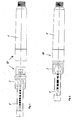
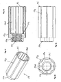
- FIG. 1 shows in a view a reservoir part 1 and a mechanism holder 3 which are connected to one another in order to form the reservoir module 10 shown in FIG.
- a piston rod 4 is further seen, which protrudes at an end facing away from the reservoir part 1 of the mechanism holder 3 in the mechanism holder 3 and of the mechanism holder 3 in a longitudinal axis L of the piston rod 4 facing feed direction to one of the mechanism holder 3 facing away, front end of the reservoir part 1 is slidably mounted.
- the reservoir part 1 is substantially circular in cross-section Hollow cylinder having at its front end a connecting portion for connection to a needle holder for an injection needle.
- the reservoir part 1 is used to receive a reservoir container, which is formed in the embodiment of an ampoule 2, which can be seen in the longitudinal section of Figure 3.
- An outlet at the front end of the ampoule 2 is sealed fluid-tight by a membrane.
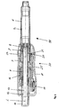
- Figure 3 shows the injection device in its entirety in a longitudinal section.
- a piston is slidably received in the feed direction on the outlet formed at the front end of the ampoule 2.
- product is displaced from the ampoule 2 and distributed through the outlet and the injection needle through.
- the advance of the piston causes the piston rod 4, which presses with its front end against the piston and thereby moves at its own feed the piston in the feed direction.
- the piston rod 4 is held by the mechanism holder 3 so that it can be moved after overcoming a certain resistance in the feed direction, but not against the feed direction.
- the backward movement of the piston rod 4 against the feed direction is prevented by a blocking device 8.
- the blocking device 8 is fixed axially by the mechanism holder 3, i. it is held in the mechanism holder 3 so that it is not movable in and against the feed direction. However, it is rotatably supported by the mechanism holder 3 about the longitudinal axis L.
- the blocking device 8 also generates the resistance that must be overcome for the forward movement.
- the blocking device 8 is shown alone in FIG. It is formed by a one-piece ring element, which on the mechanism holder 3 between two mutually spaced spaced shoulders 3b, of an inner shell of the 3 protrude radially inward, about the longitudinal axis L rotatably applied.
- the shoulders 3b form a fixing device for the axial fixing of the blocking device 8.
- the mounting of the blocking device 8 in the mechanism holder 3 is best seen from the representation of the mechanism holder 3 in Figure 5.
- a dose setting member 9 is further included in the mechanism holder 3.
- the dose setting member 9 is formed as a threaded nut and is in threaded engagement with an external thread of the piston rod 4.
- the dose setting member 9 is secured against rotation by the mechanism holder 3, but guided axially linearly movable in and against the feed direction.
- the piston rod 4 and dose setting member 9 form a spindle drive to select the product dose to be administered.
- the ampoule holder 1 and the mechanism holder 3 are rotationally and non-displaceably connected to one another and together form the reservoir module 10 of the injection device, this reservoir module 10 comprising the piston rod 4 and the dosage setting member 9 held by the mechanism holder 3 by means of the blocking device 8.
- the ampoule holder 1 and the mechanism holder 3 together form a front housing portion of the injection device. With this front housing section 1, 3, a rear housing portion 11 is positively connected.
- the rear housing portion 11 forms the carrier of a metering and actuating element 12 and together with the same and parts of a locking device and other parts of a metering and actuation module 30 of the injection device.
- a metering and actuation device comprises the other components for the selection of the product dose and the actuation of the injection device.
- it comprises the metering and actuating element 12.
- the metering and actuating device comprises a counting and display device 17 for counting and visual display of the selected Product dosage.
- the counting and display device 17 makes the dosing and actuation module 30 to a high-quality and therefore high-priced part of the injection device. While the comparatively inexpensive reservoir module 10 is designed as a disposable module, the metering and actuation module 30 is intended for repeated use with ever new reservoir modules 10.
- the metering and actuating element 12 is rotatable about the longitudinal axis L and further supported in the feed direction along the longitudinal axis L of the rear housing portion 11.
- the metering and actuating element 12 is hollow cylindrical and surrounds the piston rod 4 with a front section. A rear section of the metering and actuating element 12 projects beyond a rear end of the housing section 11.
- a rod-shaped Dosiermit matter 13 is inserted from the rear against a radially inwardly projecting shoulder of the metering and actuating element 12.
- a closure 14 is inserted against the Dosiermitnitrogen 13 in the metering and actuating element 12.
- the Dosiermit demanding 13 is axially fixed between the radially projecting shoulder of the metering and actuating element 12 and the closure 14 relative to the metering and actuating element 12.
- the Dosiermit demanding 13 is also connected against rotation with the metering and actuating element 12.
- the Dosiermit facultative 13 projects for the purpose of dosage from behind into the hollow piston rod 4 inside.
- the piston rod 4 has a connecting portion 4a (FIG.
- the connecting portion 4a is formed as a linear guide for the Dosiermitcret 13.
- a return device 16 biases the dosing and actuating element 12 elastically against the feed direction in the starting position shown in Figures 3 and 4.
- In the initial position can be made by rotation of the metering and actuating element 12 about the longitudinal axis L, the dosage.
- the distribution of the selected product dose can be effected from the initial position by axial displacement of the metering and actuating element 12.
- the restoring device 16 is formed by a helical spring acting as a compression spring, which is received in an annular gap around the metering and actuating element 12 and between a radially inwardly projecting shoulder of the housing portion 11 and a radially outwardly projecting radially outwardly shoulder of the metering and actuating element 12 is axially supported.
- the blocking device 8 fulfills a dual function. On the one hand, with its blocking elements 8a, it ensures that the piston rod 4 can not be moved back counter to the feed direction relative to the mechanism holder 3, and thus in particular relative to the piston received in the ampoule 2. In its dual function, the blocking device 8 further prevents the brake as a forward movement of the piston rod 4 in the dosing, in which the dose setting 9 is moved axially against the feed direction to the dosing and actuating element 12.
- the dose setting member 9 In the initial position shown in FIGS. 3 and 4, prior to metering, the dose setting member 9 lies in the direction of advance against an ejection stop 3c formed by the mechanism holder 3 (FIG. 5).
- the piston rod 4 is in permanent contact with the piston.
- the dose setting member 9 is moved by the threaded engagement with the piston rod 4 and the linear guide through the mechanism holder 3 from the Aus thoroughlyanschlag 3 c away on the metering and actuating element 12.
- a clear distance between a rear abutment surface of the dose setting member 9 and a front abutment surface of the metering and actuating element 12 is reduced, on the other hand however, the clearance between a front abutment surface of the dose setting member 9 and the delivery stopper 3c is increased.
- the latter distance between the discharge stopper 3c and the dosage setting member 9 is the path length by which the dose setting member 9 is moved in the course of the delivery movement of the metering and actuating element 12 and also the piston rod 4 in the feed direction because of the threaded engagement.
- the discharge stopper 3c forms a front translational stop.
- the piston rod 4 presses against the piston with its front end, which is formed by a plunger body which is not movably connected to the piston rod 4 and against the feed direction, and presses the piston in the direction of advance toward the outlet of the ampoule 2.
- the longitudinal axis L forms the rotation and translation axes of the movements that are carried out for the purpose of metering and product dispensing.
- the distance between the dose setting member 9 and the metering and actuation element 12 before the metering operation when the dose setting member 9 abuts against the delivery stopper 3c corresponds to the maximum product dose which can be selected and distributed in the course of a discharge.
- the lifting movement of the metering and actuating element 12 is the same length for each distribution. It is set by the dosage only the distance of the dose setting 9 of the Aus frequentlyanschlag 3c and thus in the course of the distribution of the dosing and actuating element 12 and the dose setting 9 together safelylegbare path length.
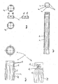
- the blocking device 8 for braking engagement has two brake elements 8b which, like the locking elements 8a, are each formed by an elastically yielding snapper.
- the blocking device 8 is formed in the embodiment of a single ring element, of which four elastic on one end face Protrude snappers axially. The snapper are distributed uniformly over the circumference of the ring element. Two opposing snapper form the locking elements 8a and the two other, also oppositely arranged snapper form the brake elements 8b.
- the piston rod 4 accordingly has two retraction locking devices 6 formed on opposite sides on the outer jacket and extending in the longitudinal direction of the piston rod 4 and two advancing brake devices 7 extending on likewise opposite sides in the longitudinal direction of the piston rod 4.
- the thread of the piston rod 4 for threaded engagement with the dose setting member 9 is formed by four remaining threaded portions 5 which extend over almost the entire length of the piston rod 4.
- the remindzusperr noiseen 6 and the feed braking devices 7 are each formed by a row of teeth. While the teeth of remindzugsperr Hughes 6 but are swept in the feed direction saw teeth with rearwardly facing, transverse to the feed direction extending locking surfaces are formed, the two rows of teeth that form the feed brake means 7, not facing forward locking surfaces with a comparable barrier effect.
- the teeth of the advancing brake devices 7 each have a softer tooth profile than the retraction locking devices 6.
- the braking engagement of the blocking device 8 with the feed brake means 7 of the piston rod 4 is not intended to prevent a feed movement of the piston rod 4, but only complicate to ensure that the piston rod 4 is not moved in the feed direction in the feed direction.
- the teeth of the advancing brake devices 7 are at their front sides and the brake elements 8b are formed at their rear sides, which contact the front sides of the teeth of the advancing brake device 7, so that to overcome the braking intervention, a threshold force must be overcome, which is not reached in the dosage. This threshold force is greater than the force required to move the teeth of the retraction locking devices 6 over the locking elements 8a in the feed direction.
- the threshold force is at least twice as large as the initial frictional force between the remindzugsausperr wornen 6 and the locking elements 8a.
- the frictional force between the latter also increases gradually only during the course of the advancing movement between two successive interlocking interventions.
- the threshold force of the braking engagement must be applied in each locking engagement immediately at the beginning of the feed movement of a locking intervention in the next following.
- the threshold force should not be so great that it is perceived by the user in the distribution as disturbing.
- An undesired advancing movement of the piston rod in response to the movement of the dosage setting member 9 in the dose selection can in principle also be effected solely by the blocking engagement of the blocking device 8. However, such a movement is more reliably prevented because of the braking engagement than by the locking intervention alone.
- connection between the reservoir module 10 and the metering and actuation module 30 is form-fitting.
- the front housing section 1, 3 and the rear housing section 11 are axially linearly guided directly adjacent to each other to prevent relative rotation in the connection and in the connected state.
- the axial guides 3d of the mechanical holder 3, which form the linear guide with one or more corresponding engagement elements of the rear housing section 11, can be easily recognized.
- the axial guides 3d are formed by guide surfaces on guide ribs; they could also be formed by guide surfaces in axially extending recesses. In this way, axial guide channels are obtained.
- the guide ribs are axially tapered so that leading insertion funnels for the one or more engagement elements of the rear housing section 11 are formed in the guide channels. For even better centering of the housing sections 1, 3 and 11 at the beginning of the connection, the guide ribs are also in the radial direction rejuvenated.
- the one or more engagement elements of the rear housing section 11 is or are preferably formed like the axial sections 3d on the mantle counter surface, ie the inner lateral surface, of the rear housing section 11.
- the locking engagement consists between a female, first locking element 3a of the mechanism holder 3 ( Figure 5) and a locking ring 20 which is connected to the rear housing portion 11 radially movable, but not axially movable.
- the locking ring 20 forms a male, second locking element 21 engaging radially directly in the first locking element 3a.
- Figures 3 and 4 show the locking element 21 in locking engagement with the locking element 3a.
- the locking element 3 a is formed by an annular web and a groove, which rotate on the outer jacket of the mechanism holder 3.
- the ring land forms a rear side wall of the groove.
- the second locking element 21 is formed by a cam, which protrudes radially inwardly from the inner shell of the locking ring 20 and is pressed in locking engagement by a restoring device 24 radially inwardly over an inner circumferential surface of the rear housing portion 11 projecting into the female locking element 3a.
- the locking ring 20 is supported in its entirety in the radial direction by means of the restoring device 24 on an inner shell surface formed by the housing section 11, so that the restoring device 24 presses against the outer shell of the locking ring 20 approximately in the radial extension of the locking element 21.
- the locking ring 20 surrounds the mechanism holder 3 and is in its entirety against the restoring force of the return means 24 radially movable back and forth, so that the second locking element 21 in and out of the locking engagement with the first Locking element 3a can be brought.
- the rear housing portion 11 forms a tight sliding guide for the radial movement of the locking ring 20.
- At its locking element 21 radially opposite side of the locking ring 20 forms a release button 22 for the user.
- a guide cam protrudes radially from the outer circumferential surface of the locking ring 20 facing away from the locking element 21.
- the release position therefore coincides with the foremost displacement position, which occupies the metering and actuating element 12 when it in turn abuts against the Aus featureanschlag 3c of the mechanism holder 3 in the course of its Aus wellzi to the dose setting 9 and the dose setting.
- a mechanical stop for the metering and actuation element 12 is formed by a stop element 31 of the metering and actuation device.
- a reset holder ring which serves to reset the display 17, the stop element 31.
- the stop of the metering and actuating element 12 against this stop element 31 defines the release position of the metering and actuating element 12 in this case, which defined by the stop element 31 release position corresponds to that which is defined by the abutment of the dose setting 9 at the Aus commonlyanschlag 3c.
- FIG 8 shows the locking lock 25. It is formed integrally in the embodiment of a locking slide.
- the locking catch 25 has a plate-shaped main body, which extends axially in the assembled state, as shown for example in Figure 4. At one end of the main body protrudes a web 26 at right angles. In the mounted state, the web 26 extends radially up to against the metering and actuating element 12.
- the web 26 serves to fasten the locking lock 25 on the metering and actuating element 12, which has two axially spaced formed on an outer circumferential surface ring lands, the driver 15a and 15b form.
- the front driver 15b simultaneously forms the support shoulder for the return device 16.
- the locking catch 25 protrudes with its web 26 and is axially enclosed on both sides by the two drivers 15a and 15b.
- the main body of the lock catch 25 is provided with an axial recess 27 open to the front end of the lock catch 25.
- axially extending locking tongues 28 are formed.
- the two locking cams 23 of the locking ring 20 are arranged so that each one of these locking cam 23 presses against one of the locking tongues 28, as long as the metering and actuating element 12 does not occupy the release position.
- the return device 24 for the locking element 21 extends during the axial movement of the locking catch 25.
- Einschausnaturalept 29 are further formed, which define the release position of the metering and actuating element 12.
- Per locking cam 23 each have a Einschreibausnaturalung 29 is provided.
- the position of Einschreibausnaturalept 29 is chosen so that they only come into overlap with the locking cam 23 and thereby allow retraction of the locking cam 23 when the metering and actuating element 12 has been advanced to its release position.
- the locking lock could also be made in one piece with the metering and actuating element 12.
- the training as a separate part offers advantages in terms of manufacturing, assembly and the interaction of the metering and actuating element 12 with the piston rod 4.
- the locking catch 25 at its from the locking element 21 opposite outer side is supported on an inner circumferential surface of the housing 11. In this way, the stability of the lock for the locking engagement is increased.
- the housing 11 forms an axial guide for the locking catch 25th
- the metering and actuation module 30 and the new reservoir module 10 are aligned axially with respect to each other so that their two longitudinal axes are aligned with each other. Subsequently, the reservoir module 10 is inserted with its rear end into the forwardly open housing 11 of the metering and actuation module 30.
- the housing section 1, 3 and the housing portion 11 centered at the tapered ends of the guide ribs 3d of the mechanism holder 3. While sliding the two housing sections are axially linearly guided together in a predetermined by the linear guide rotational angular position, until the housing sections 1, 3 and 11 a Occupy the connection end position in which the locking engagement of the locking elements 3a and 21 can be made or self-adjusting.
- the metering and actuating element 12 is locked in predetermined rotational angle positions relative to the rear housing portion 11.
- the linear guide of the housing sections 1, 3 and 11 and the rotational locking position of the metering and actuating element 12 are coordinated so that the rotationally secured engagement of the metering and actuating element 12 with the piston rod 4 in each locking position of the metering and actuating element 12 and each rotational angular position, in which the housing sections 1, 3 and 11 are linearly guided together, is produced.
- the locking element 21 is held by the locking catch 25 in its radially innermost position.
- the metering and actuation module 30 and the reservoir module 10 can not be pushed together into the final connection position and therefore not connected to each other, since the annular web formed on the outer shell of the mechanism holder 3, which mit stipulate the first locking element 3a, before against the second locking element 21 comes to rest on stop.
- the annular land can be reduced to a short tangential radial projection, if it is ensured that the housing sections 1, 3 and 11 can be assembled only in the rotational angular position, in which such a projection and the second locking member 21 to lie in axial alignment come.
- the annular ridge or radial projection could be the first Locking element 3a also form alone, since it is the essential function of the first locking element 3a, to allow the establishment of the connection between the reservoir module 10 and the metering and actuation module 30 only when the metering and actuating element 12 assumes its release position.
- the metering and actuation element 12 would ensure that the dose setting member 9 is in its zeroing position when it is connected to the delivery stop 3c of the mechanism holder when establishing the connection between the reservoir module 10 and the metering and actuation module 30 3 abuts.
- the user presses the metering and actuating member 12 axially relative to the rear housing portion 11 to the release position.
- the locking cams 23 can be moved into the engagement receptacles 29 of the locking catch 25.
- the user therefore not only presses the metering and actuating element 12 to at least in the release position, but at the same time by means of the release button 22, the first locking element 20 from the locking engagement.
- the reservoir module 10 can now be moved axially over the annular web of the first locking element 3 a and further inserted into the rear housing section 11. The user can release the unlock button 22.
- the reservoir module 10 and the metering and actuation module 30 are now connected to each other in a defined manner with respect to the position of the dose setting member 9 and the piston rod 4. If the dosage setting member 9 has still shown a clear distance from the Aus thoroughlyanschlag 3c before making the locking engagement, this distance is eliminated due to the action of the metering and actuating element 12 required for establishing the connection. An accompanying one Product release can be tolerated and may even be desirable for the purpose of priming the injection needle.
- the counting and display device 17 is preferably zeroed.
- the dosage is effected by rotation of the metering and actuating element 12 about the longitudinal axis L and relative to the housing portion 11. Since the Dosiermit supportive 13 is connected against rotation with the metering and actuating element 12 and in turn engages against rotation in the piston rod 4, takes the dosing and Actuator 12 in the rotary metering the piston rod 4 with. Due to the threaded engagement between the piston rod 4 and the dose setting member 9 and the linear guide of dose setting 9 through the mechanism holder 3, the dose setting 9 performs a predetermined by the thread pitch of the mutual thread engagement, axial translational dosing in the direction of the dosing and actuating element 12. The metering and actuating element 12 forms a rear translation stop 12c, which limits the translational metering movement of the dose setting member 9 and thereby defines the maximum adjustable delivery stroke.
- Counting and indicating device 17 counts the dose units corresponding to the rotational angle position of metering and actuating element 12 and visually displays them.
- the dosing process is completed.
- the distribution of the selected product dose is effected by means of the discharge movement of the dosing and actuating element 12 pointing in the direction of advance of the piston.
- the dosing and actuating element 12 abuts against the dosage setting member 9 and takes it with him.
- the dose setting member 9 abuts in the course of Aus.rois against the Aus.anschlag 3 c of the mechanism holder 3, the Aus thoroughlyroisen the metering and actuating element 12 and the Product distribution finished.
- the return device 16 counter is preferably moved by the return device 16 counter to the feed direction back into a new starting position for a new dosage and product distribution.
- the counting and display device 17 is preferably coupled to the metering and actuating element 12 so that it has meanwhile been returned to zero. If appropriate, it has means for counting and displaying the total amount of product already distributed and thus the remaining amount of product in the ampoule 2.
- the metering and actuation element 12 In order to release the reservoir module 10 from the metering and actuation module 30, the metering and actuation element 12 is moved into the release position, i. until it stops against the dosage setting 9, moved forward. In this position, the user can release the locking engagement again by pressing the unlocking button 22 and disconnect the reservoir module 10 from the metering and actuation module 30.
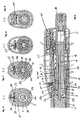
- FIGS. 9 to 13 show in a longitudinal section and four cross sections a second embodiment of an injection device.
- the injection apparatus of the second embodiment is similar to that of the first embodiment with respect to the lock and the lock-lock 25 so that reference is made to the relevant description of the first embodiment.
- the lock-up lock 25 of the second embodiment is identical to that of the first embodiment in all functional details. The same applies to the locking elements 3a and 21st
- the injection device of the second embodiment differs from the first embodiment by the engagement and the movement of the components involved in the dosage. Furthermore, beyond the functions of the mechanism holder of the first embodiment, the mechanism holder in particular fulfills the function of positioning the dose setting member in discrete rotational angular positions which are variable relative to the mechanism holder for the purpose of metering.
- the blocking device of the second embodiment is made simpler than that of the first embodiment. In the following, only the differences compared to the first embodiment will be described in the first place, for components that are identical in their basic function to the same components of the first embodiment, but in details, 30iger numbers with the same final digit or exactly the same reference numerals in the first embodiment. As far as the second embodiment, no comments are made, the corresponding statements to apply to the first embodiment.
- the relative to the rear housing portion 11 axially linearly movable and rotatable about the longitudinal axis L metering and actuating element 32 is connected against rotation with the dose setting 39.
- the metering and actuating element 32 and the dose setting member 39 are movable relative to each other and relative to the housing sections 1, 3 and 11 in and against the feed direction.
- the piston rod 4 is held against rotation by the mechanism holder 3.
- the functionally identical with the first embodiment stuntzugsperr worn 6 prevents in cooperation with locking elements integrally formed on the mechanism holder 3 blocking device 38, a movement of the piston rod 4 against the feed direction, but allows movement in the feed direction.
- the metering and actuating element 32 forms a sliding guide for the piston rod 4.
- the blocking elements form at the same time the retraction lock and the rotation lock for the piston rod 4.
- the dosage setting member 39 thus performs a rotary dosing movement and a translatory dosing movement relative to the front housing section during dosing, while the piston rod 4 is stationary.
- the piston rod 4 is advanced by the path length which corresponds to the set by the dosage clear distance between a stop surface of the dose setting 39 and the delivery stop 3c of the mechanism holder 3.
- the translational metering movement of the dosage setting member 39 is limited against the advancing direction by a rear translation stop 11c, which the rear housing portion 11 itself forms directly.
- the longitudinal axis L forms the axis of rotation and translation of the components involved in metering and product dispensing.
- the front housing section 1, 3 forms a sliding guide for the dosage setting member 39.
- an inner circumferential surface of the mechanical holder 3 and an outer circumferential surface of the dose setting member 39 are in sliding contact with each other.
- the metering and actuating element 32 is engaged with an inner circumferential surface of the dose setting member 39 in engagement with the non-rotational connection between the dosage setting member 39 and the metering and actuating element 32 to form.
- the piston rod 4 via the retraction locking device 6 also has no own braking device.
- the front sides of the saw teeth of the retraction locking device 6 rather alone form the braking device.
- the piston rod 4 of the second embodiment can be replaced by the piston rod of the first embodiment. Accordingly, in this case by the mechanism holder 3 of the second embodiment, at least one braking element, preferably both brake elements of the first embodiment would be formed.
- Figures 14 to 16 show the mechanism holder 3 of the second embodiment in a perspective view, a side view and in the registered in side view cross-section A-A.
- the mechanism holder 3 is designed as a one-piece sleeve part as in the first embodiment, preferably as a plastic injection molded part. It has on the outer jacket of a front sleeve portion on a bead 3e. The front sleeve portion is inserted into the reservoir part 1 and by means of the bead 3e at least for the user inextricably locked to the reservoir part 1.
- the locking element 3a is formed on a central sleeve portion of the mechanism holder 3 as in the first embodiment.
- the axial guides 3d are formed by guide ribs which project radially on the outer circumference of the rear sleeve section. More specifically, the axial guide is formed by the axially extending, straight side walls of these guide ribs, so that, as in the first embodiment, axial guide channels are obtained.
- the guide ribs protrude from the Middle sleeve portion of like fingers to the rear end of the mechanism holder 3, where they taper axially tapered.
- the axial guide 3d serves to guide the linear movement of the rear housing section 11 when the reservoir module 10 is connected to the metering and actuation module 30.
- the amount of an inner circumferential surface of the rear housing section 11 is corresponding and in shape adapted engagement elements 11 d radially inwardly from.
- each of the axial guides 3d protrudes an engagement member 11 d and is linearly guided by the axial guide 3d, when the front housing section 1, 3 and the rear housing section 11 are pushed into each other for connecting. In this way, it is ensured that between the front housing portion 1, 3 and the rear housing portion 11, no relative rotation can take place when in the course of connecting the rotationally secured engagement between the metering and actuating element 32 and the dose setting member 39 is made.
- the guide ribs tapering axially tapered at their rear ends and the guide channels are so widened to insertion funnels, a centering between the front housing portion 1, 3 and the rear housing portion 11 is facilitated for the purpose of connecting.
- the guide ribs taper at their ends also radially to the lateral surface of the mechanism holder 3, whereby the centering of the housing sections 1, 3 and 11 in a predetermined by the axial guide 3d rotational angular position relative to each other even easier.
- the dose setting member 39 is fixed relative to its rotational angular position relative to the front housing portion 1, 3, said fixation is solvable allow the required for the dosage rotation of the dose setting 39. Therefore, on the one hand to allow the metering movement of the dose setting 39, but on the other hand, an undesirable metering movement by establishing the connection between the front Housing section 1, 3 and the rear housing portion 11 to prevent the dosage setting member 39 is fixed by the mechanism holder 3 by means of a releasable latching connection in discrete rotational angular positions.
- Figures 17 to 20 show the dose setting member 39 in individual representations.
- a plurality of latching receptacles 39g are formed on the outer circumferential surface of the dosage setting member 39 distributed over the circumference at a regular pitch.
- Each of the locking receptacles 39g is formed by a straight, axially extending groove with a rounded contour extending in cross-section.
- the mechanism holder 3 is provided with two latching noses 3g (FIGS. 15 and 16).
- the two locking lugs 3g protrude in the rear sleeve portion of the mechanism holder 3 from an inner circumferential surface of the mechanism holder 3 radially inwardly. They are arranged diametrically opposite each other.
- the locking engagement is designed so that the rotational angle fixation of dose setting 39 is so stable that when connecting the front housing portion 1, 3 with the rear housing portion 11 no unwanted dosing of the dose setting 39 can take place, if the rotational coupling of the dosing and actuating element 32 is made with the metering and actuating element 32.
- the latching connection between the mechanism holder 3 and the dosage setting member 39 gives as an advantageous side effect a tactile signal during dosing.
- the rear sleeve portion of the mechanism holder 3 is cut out in the respective jacket region, so that the spring element 3f is obtained as a circumferentially extending ring segment which is exposed axially on both sides.
- axial guides 39d for non-rotatable engagement of the dose setting member 39 with the metering and actuation element 32.
- the metering and actuation element 32 is provided with at least one engagement element to provide axial linear guidance, i. the rotation, to get between the metering and actuating element 32 and the dose setting 39.
- the axial guides 39d are again guide channels, which are formed by a plurality of axially extending guide ribs. Each of the guide ribs is axially and radially tapered at its rear end facing the metering and actuation element 32 in order to facilitate the centering between the metering and actuation element 32 and the dose setting element 39 in the production of the rotationally secure engagement.
- the axial linear guide of dose setting 39 and metering and actuating element 32 thus the same construction as for the axial linear guide of the housing sections 1, 3 and 11 is used.
- 39 rotational stops 39h are formed at a front end of the dose setting member.
- the rotational stops 39h in the front end position occupied by the dosage setting member 39 immediately after a product dispensing or before a dose selection are engaged with rotational counterstops 3h formed on the mechanism holder 3 (FIG. 16).
- the rotational stops 39h protrude axially from a front end face of the dosage setting member 39, and the rotational counter stops 3h project from an axially facing end face of the Mechanism holder 3, which forms the Auf commonlyanschlag 3c, the rotational stops 39h axially opposite.
- the engagement between the rotational stops 39h and the rotational counter-stoppers 3h is such as to permit rotational metering movement in a rotational direction which causes a translational metering movement of the dose setting member 39 away from the delivery stopper 3c, but rotational metering movement in the reverse direction of rotation in the forward axial end position prevented.
- the height, i. the axial length, all of the rotational stops 3h, 39h, 11i and 39i is matched to the pitch of the engaged metering threads of the piston rod 4 and the dose setting member 39.
- the rotational stops are axially so short that the rotary metering movement is not hindered, by which the dose setting member 39 is moved away from the respective translation stop 3 c or 11 c.
- the dosage setting member 39 is screwed onto the piston rod 4 up to a predetermined axial position, as can be seen in FIG. Subsequently, the Piston rod 4 is introduced with the screwed dose setting 39 from behind into the mechanism holder 3 until the blocking device 38 comes into locking engagement with the remindzugsssperr adopted 6 of the piston rod 4 and further the rotationally secured engagement between the rotational stops 39h of the dose setting 39 and the VerFD brieflyanelle 3h of the mechanism holder 3 is made ,
- the dosage setting member 39 is axially linearly guided in a rotational locking position by the locking engagement between the locking lugs 3g and the locking receptacles 39g of the mechanism holder 3 until the dose setting member 39 abuts the Aus thoroughlyanschlag 3c of the mechanism holder 3. In this front end position of the dose setting member 39 relative to the mechanism holder 3, the rotation-proof engagement between the rotation stops 3h and 39h is simultaneously already established.
- the rear housing portion 11 of the fully assembled metering and actuation module 30 is pushed onto the mechanism holder 3, wherein the mechanism holder 3 and the rear housing portion 11 due to the axial guides 3d and the engagement elements 11 d of the rear housing portion 11 can center each other and be guided linearly to each other after centering due to the guiding engagement.
- the dosing and actuating element 32 passes into the rotationally secured engagement with the dose setting member 39, wherein here also by a the axial guides 3d and engagement elements 11 d corresponding linear guide can first take place a certain centering.
- the metering and actuating element 32 is in discrete Drehwinkelrastpositionen with the rear housing portion in a latching engagement and is guided axially linearly in the latching engagement, ie in the respective rotational locking position.
- the rotation angle difference between two consecutive Angular locking positions corresponds to a dose unit.
- the linear guide between the mechanism holder 3 and the rear housing section 11 on the one hand and the discrete rotational angular positions of the dose setting member 39 relative to the mechanism holder 3 (locking lugs 3g and latching receptacles 39g) and the Drehwinkelrastpositionen the metering and actuating element 32 relative to the rear housing portion 11 on the other hand are so that the linear displacement of the two housing sections 1, 3 and 11 always takes place in such a rotational angle position that the dosage setting member 39 and the metering and actuating element 32 are also aligned relative to one another for their rotationally engaged engagement, so that during the connection of the reservoir module 10 With the metering and actuation module 30, there is no relative rotation between the components involved in the metering.
- anti-rotation devices can be provided which prevent undesired reaction movements of the piston rod 4 in the two axial end positions of the dose setting member 9 of the first embodiment.
- Figure 21 shows the two anti-rotation, which are shaped in the same way as the anti-rotation of the second embodiment.
- the rotational counter-abutments formed on the housing sections 1, 3, and 11 in the first embodiment are formed by the blocking device 8 and the metering and actuating element 12, respectively.
- a plurality of rotational stops 8h are formed, which project axially onto the dose setting member 9.
- the second rotation stopper pair is formed between the dose setting member 9 and the rear translation stopper 12c.
- the dose setting member 9 is provided on its rear side with torsion stops 9i as in the second embodiment, which engage in the rear axial end position of the dose setting member 9 into engagement with the rotational stops 12i. In the rear axial end position of the dose setting 9, only the rotary metering movement is allowed by the rear Verdichtanschlagschreib 9i / 12i, which causes a translational metering movement of dose setting 9 in the feed direction.
Abstract
Description
Die Erfindung betrifft Verabreichungsgeräte, vorzugsweise Injektionsgeräte, die eine Auswahl einer auszuschüttenden Produktdosis erlauben und bevorzugt für medizinische, therapeutische, diagnostische, pharmazeutische oder kosmetische Anwendungen vorgesehen sind. Bevorzugte Beispiele von Injektionsgeräten sind Injektionspens, insbesondere Semidisposable Pens. Ein Verabreichungsgerät nach der Erfindung kann beispielsweise auch ein Inhalationsgerät oder ein Gerät zur dosierten Abgabe eines oral einzunehmenden Produkts sein.The invention relates to administration devices, preferably injection devices, which allow a selection of a product dose to be distributed and are preferably provided for medical, therapeutic, diagnostic, pharmaceutical or cosmetic applications. Preferred examples of injection devices are injection pens, in particular semidisposable pens. An administration device according to the invention may, for example, also be an inhalation device or a device for metered delivery of an orally administered product.
Verabreichungsgeräte sollen im Allgemeinen handlich und daher klein sein, andererseits aber eine möglichst hohe Funktionalität aufweisen. Dem ersten Aspekt werden sogenannte Injektionspens, die ihrer schlanken Form wegen so bezeichnet werden, ohne weiteres gerecht. Ein wesentlicher Aspekt im Hinblick auf die Funktionalität ist die Fähigkeit der freien Auswahl der mit einer Injektion zu injizierenden Produktdosis. Die Möglichkeit der Produktdosisauswahl ist insbesondere in solchen Anwendungen von Vorteil, in denen ein Verwender sich das zu injizierende Produkt selbst verabreicht, wie dies beispielsweise in der Diabetestherapie oder in der Hormonverabreichung üblich ist, um nur zwei bevorzugte Anwendungsbeispiele zu nennen. Mit der Möglichkeit der flexiblen Produktdosisauswahl einher geht jedoch ein entsprechender technischer Aufwand, der nicht nur den Preis erhöht, sondern auch die betreffenden Geräte vergrößert.Delivery devices should be generally handy and therefore small, but on the other hand have the highest possible functionality. The first aspect, so-called Injektionspens, because of their slim form because of so called, readily meet. A key aspect in terms of functionality is the ability to freely select the dose of product to inject with an injection. The possibility of product dose selection is particularly advantageous in those applications where a user self-administers the product to be injected, as is common in, for example, diabetes therapy or hormone administration, to name just two preferred examples of use. However, with the possibility of flexible product dose selection is accompanied by a corresponding technical effort, which not only increases the price, but also increases the devices concerned.
Ein Injektionspen mit Produktdosisauswahl wird in der US-PS 4,973,318 beschrieben. Der Pen weist eine Kolbenstange auf, die von einer Gewindestange gebildet wird, und dazu dient, einen Kolben in einer Produktampulle zu verschieben und dadurch das Produkt auszuschütten. Der Pen weist eine vordere Gehäusehülse und eine hintere Gehäusehülse auf, die um eine gemeinsame Längsachse relativ zueinander verdrehbar sind. Durch die Relatiwerdrehung der beiden Gehäusehülsen wird die Produktdosis ausgewählt. Die Kolbenstange steht mit einer Gewindemutter in einem Gewindeeingriff. Die Gewindemutter bildet einen vorderen Abschnitt eines hülsenförmigen Dosier- und Betätigungselements. Dieses Dosier- und Betätigungselement ragt an einem hinteren Ende in die hintere Gehäusehülse ein und ist mit der hinteren Gehäusehülse verdrehgesichert verbunden, aber relativ zu der hinteren Gehäusehülse in Längsrichtung der Kolbenstange hin und her verschiebbar. Wird die hintere Gehäusehülse zum Zwecke der Dosisauswahl gedreht, so wird das Dosier- und Betätigungselement zwangsweise mitgedreht. Da die Kolbenstange jedoch mit der vorderen Gehäusehülse verdrehgesichert verbunden ist, wird das Dosier- und Betätigungselement aufgrund der Drehbewegung weiter aus der hinteren Gehäusehülse nach hinten hinaus bewegt. Hierbei wird die Gesamtlänge der Anordnung aus Kolbenstange und Dosier- und Betätigungselement vergrößert und ein lichter Abstand zwischen dem vorderen Ende des Dosier- und Betätigungselements und einer Anschlagfläche des Gehäuses vergrößert. Dieser lichte Abstand entspricht dem maximal möglichen Hub, wenn das Dosier- und Betätigungselement zusammen mit der Kolbenstange zum Zwecke der Produktausschüttung in Richtung auf ein vorderes Ende des Pens vorgeschoben wird. Wegen dieser recht einfachen Dosiermechanik entspricht der Hub der Ausschüttbewegung der jeweils eingestellten Produktdosis und ist somit variabel.A product dose selection type injection pen is described in U.S. Patent No. 4,973,318. The pen has a piston rod which is formed by a threaded rod and serves to displace a piston in a product ampule and thereby pour out the product. The pen has a front housing sleeve and a rear housing sleeve, which are rotatable relative to one another about a common longitudinal axis. Due to the relative rotation of the two housing sleeves, the product dose is selected. The piston rod is threadedly engaged with a threaded nut. The threaded nut forms a front portion of a sleeve-shaped metering and actuating element. This metering and actuating element projects at a rear end into the rear housing sleeve and is connected secured against rotation with the rear housing sleeve, but displaceable relative to the rear housing sleeve in the longitudinal direction of the piston rod back and forth. If the rear housing sleeve is rotated for the purpose of dose selection, the metering and actuating element is forcibly rotated. However, since the piston rod is connected non-rotatably to the front housing sleeve, the metering and actuating element is moved further out of the rear housing sleeve due to the rotational movement. Here, the total length of the assembly of piston rod and metering and actuating element is increased and increased a clear distance between the front end of the metering and actuating element and a stop surface of the housing. This clear distance corresponds to the maximum possible stroke, when the metering and actuating element is advanced together with the piston rod for the purpose of product distribution in the direction of a front end of the pen. Because of this fairly simple dosing mechanism corresponds to the stroke of the dispensing movement of each set product dose and is thus variable.
Aus der WO 97/17096 ist ein Injektionspen bekannt, der unabhängig von der ausgewählten Produktdosis stets den gleichen Ausschütthub aufweist. Die Kolbenstange ist ebenfalls als Gewindestange ausgebildet und verdrehgesichert mit dem Gehäuse des Pens verbunden. Eine Dosiseinstellmutter steht mit der Kolbenstange in einem Gewindeeingriff. Die Kolbenstange ragt in ein hülsenförmiges Dosier- und Betätigungselement. Das Dosier- und Betätigungselement und die Dosiseinstellmutter dieses Pens sind separate Teile. Das Dosier- und Betätigungselement ist mit der Dosiseinstellmutter verdrehgesichert, aber in Längsrichtung der Kolbenstange verschieblich verbunden. Für diesen Eingriff umgibt das Dosier- und Betätigungselement die Dosiseinstellmutter. Für die Auswahl der Produktdosis wird das Dosier- und Betätigungselement um die Längsachse verdreht. Die Dosiseinstellmutter wird hierbei mitgedreht. Aufgrund des Gewindeeingriffs mit der Kolbenstange, der Linearführung der Dosiseinstellmutter an dem Gehäuse und der Sperrung der Kolbenstange gegen eine Bewegung entgegen der Vorschubrichtung wird die Dosiseinstellmutter bei der Drehbewegung entlang der Kolbenstange nach hinten und damit tiefer in das Dosier- und Betätigungselement hinein bewegt. Zwischen dem vorderen Ende der Dosiseinstellmutter und einem in Vorschubrichtung gegenüberliegenden Anschlag des Gehäuses ergibt sich ein lichter Abstand, der dem bei der Ausschüttbewegung von der Kolbenstange und der Dosiseinstellmutter gemeinsam zurücklegbaren Weg und damit der Produktdosis entspricht. Zur Bildung der verdrehgesicherten Verbindung zwischen dem Dosier-und Betätigungselement und der Dosiseinstellmutter ist eine Überlappung dieser beiden Teile entlang der Längsachse erforderlich, wodurch der Durchmesser des Pens vergrößert wird. Bei Verwendung des Dosiermechanismus in einem Semidisposable Injektionspen wird der Zusammenbau der Teile solch eines Pens erschwert, falls die Dosiseinstellmutter einerseits und das Dosier- und Betätigungselement andererseits je Bestandteil von Penteilen sind, die miteinander verbunden werden müssen.From WO 97/17096 a Injektionspen is known, which always has the same delivery stroke regardless of the selected product dose. The piston rod is also designed as a threaded rod and secured against rotation connected to the housing of the pen. A dose setting nut is threadedly engaged with the piston rod. The piston rod protrudes into sleeve-shaped metering and actuating element. The metering and actuation element and the dose setting nut of this pen are separate parts. The metering and actuating element is secured against rotation with the dose setting nut, but slidably connected in the longitudinal direction of the piston rod. For this procedure, the dosing and actuating element surrounds the dose setting nut. For the selection of the product dose, the metering and actuating element is rotated about the longitudinal axis. The dose setting nut is turned in this case. Due to the threaded engagement with the piston rod, the linear guide of the dose setting on the housing and the blocking of the piston rod against movement against the feed direction, the dose setting is moved during the rotational movement along the piston rod to the rear and thus deeper into the dosing and actuating element. Between the front end of the dose setting nut and an opposite stop in the feed direction of the housing, there is a clear distance, which corresponds to the common zurücklegbaren during the dispensing movement of the piston rod and the dose setting mother way and thus the product dose. To form the rotationally secured connection between the metering and actuating element and the dose setting nut, an overlap of these two parts along the longitudinal axis is required, whereby the diameter of the pen is increased. When using the metering mechanism in a semi-disposable injection pen, the assembly of the parts of such a pen is made more difficult if the dose setting nut on the one hand and the metering and actuating element on the other hand each part of Penteilen, which must be connected to each other.
Aus der EP 0 594 349 A1 ist ein Verabreichungsgerät gemäß dem Oberbegriff des Patentanspruchs 1 bekannt. Eine Kolbenstange mit einem Gewinde ist vorgesehen, wobei mittels einer Drehbewegung ein Kolben voranbewegt wird, der auf ein Reservoir einwirkt, um ein Produkt aus dem Verabreichungsgerät auszuschütten. Da keine Linearbewegung für die Kolbenstange vorgesehen ist, sondern eine Drehbewegung, ist es möglich, dass die mit einem Außengewinde versehene Kolbenstange am Ende ihrer für den Kolben gedachten Vortriebsbewegung die Vortriebsbewegung in eine umgekehrte Bewegung wandelt, so dass das auszuschüttende Produkt wieder zurückgesaugt werden könnte. Um diesem Nachteil entgegenzuwirken, wird eine Sperre vorgesehen, die eine Umkehr der Vortriebsbewegung in eine Rückwärtsbewegung verhindern soll.From EP 0 594 349 A1 an administration device according to the preamble of
Es ist eine Aufgabe der Erfindung, ein Verabreichungsgerät mit Produktdosisauswahl zu schaffen, das schlank und preiswert ist und einen konstanten Ausschütthub ermöglicht.It is an object of the invention to provide a product dosage range delivery device that is slim, low cost, and provides a constant delivery stroke.
Eine andere Aufgabe ist es, eine Dosiermechanik eines Semidisposable Pen oder anderen Verabreichungsgeräts so zu gestalten, dass der Zusammenbau des Geräts bei einem Austausch eines Reservoirmoduls vereinfacht wird.Another object is to design a metering mechanism of a semidisposable pen or other delivery device so that the assembly of the device when replacing a reservoir module is simplified.
Ein Verabreichungsgerät, wie die Erfindung es betrifft, weist ein Gehäuse, ein Reservoir für ein ausschüttbares, vorzugsweise injizierbares Produkt und einen Kolben auf, der in dem Reservoir in eine Vorschubrichtung auf einen Reservoirauslass zu verschiebbar aufgenommen ist, so dass durch eine Verschiebung des Kolbens in die Vorschubrichtung Produkt durch den Reservoirauslass hindurch ausgeschüttet wird. Das Reservoir kann von einem Behältnis gebildet werden, das von dem Gehäuse aufgenommen ist. So kann insbesondere eine Ampulle das Reservoir bilden. Das Reservoir kann grundsätzlich aber auch unmittelbar von dem Gehäuse selbst gebildet werden, d.h. ohne Zwischenschaltung eines Produktbehältnisses. Bei dem Produkt handelt es sich vorzugsweise um eine Flüssigkeit für medizinische, therapeutische, diagnostische, pharmazeutische oder kosmetische Anwendungen. So kann das Produkt beispielsweise Insulin, ein Wachstumshormon oder auch flüssige oder breiförmige Nahrung sein. Das Verabreichungsgerät wird vorzugsweise in solchen Verwendungen eingesetzt, in denen ein Benutzer sich das Produkt selbst verabreicht, wie dies beispielsweise in der Diabetestherapie üblich ist. Die Verwendung im stationären und ambulanten Bereich durch Ärzte oder geschultes Personal soll jedoch nicht ausgeschlossen sein.An administering device according to the invention comprises a housing, a reservoir for a pourable, preferably injectable product and a piston which is slidably received in the reservoir in a direction of advance to a reservoir outlet, so that by displacement of the piston in the feed direction product is distributed through the Reservoirauslass through. The reservoir may be formed by a receptacle received by the housing. Thus, in particular, an ampoule can form the reservoir. In principle, however, the reservoir can also be formed directly from the housing itself, i. without the interposition of a product container. The product is preferably a liquid for medical, therapeutic, diagnostic, pharmaceutical or cosmetic applications. For example, the product may be insulin, a growth hormone, or liquid or creamy food. The delivery device is preferably used in those applications where a user self-administers the product, as is common in diabetes therapy, for example. However, the use in inpatient and outpatient care by doctors or trained personnel should not be ruled out.
Das Verabreichungsgerät umfasst ferner eine Kolbenstange, die dazu dient, den Kolben in die Vorschubrichtung zu bewegen. Die Kolbenstange kann mit dem Kolben fest, d.h. ständig, verbunden sein, worunter auch eine einstückige Ausbildung von Kolben und Kolbenstange verstanden werden soll. In bevorzugter Ausführung sind der Kolben und die Kolbenstange jedoch als separate Bauteile ausgeführt, und es drückt zum Zwecke der Produktausschüttung die Kolbenstange mit einem vorderen Ende gegen eine Rückseite des Kolbens.The delivery device further comprises a piston rod which serves to move the piston in the direction of advance. The piston rod may be fixed to the piston, i. constantly, be connected, including an integral formation of piston and piston rod to be understood. In a preferred embodiment, however, the piston and the piston rod are designed as separate components, and it presses for the purpose of product distribution, the piston rod with a front end against a rear side of the piston.
Des Weiteren umfasst das Verabreichungsgerät ein Dosier- und Antriebselement, mit dem relativ zu dem Gehäuse eine Dosierbewegung zur Auswahl einer Produktdosis und eine Ausschüttbewegung zur Ausschüttung der Produktdosis ausführbar sind. Die Ausschüttbewegung erfolgt vorzugsweise in die Vorschubrichtung, und die Dosierbewegung ist vorzugsweise eine Drehbewegung um eine zu der Vorschubrichtung parallele Achse. Das Dosier- und Antriebselement ist mit der Kolbenstange in einem Eingriff, der eine Mitnahme der Kolbenstange bei der Dosierbewegung bewirkt, aber eine Ausschüttbewegung des Dosier- und Antriebselements relativ zu der Kolbenstange nicht behindert oder zumindest zulässt. Vorzugsweise ist der Eingriff des Dosier- und Antriebselements mit der Kolbenstange formschlüssig. Falls die Dosierbewegung eine Drehbewegung ist, wird durch den Eingriff zwischen dem Dosier- und Antriebselement und der Kolbenstange eine um die Drehachse der Drehbewegung verdrehgesicherte Verbindung geschaffen.Furthermore, the administration device comprises a metering and drive element with which a metering movement for selecting a product dose and a dispensing movement for distributing the product dose can be carried out relative to the housing. The dispensing movement is preferably in the feed direction, and the metering movement is preferably a rotary movement around an axis parallel to the feed direction. The metering and drive element is in engagement with the piston rod, which causes entrainment of the piston rod during the metering movement, but does not hinder or at least permit a delivery movement of the metering and drive element relative to the piston rod. Preferably, the engagement of the metering and drive element with the piston rod is positively. If the metering movement is a rotary movement, the connection between the metering and drive element and the piston rod creates a connection secured against rotation about the axis of rotation.
Schließlich umfasst das Verabreichungsgerät ein Dosiseinstellglied, das mit der Kolbenstange und dem Gehäuse je in einem Eingriff steht. Durch den Eingriff mit der Kolbenstange einerseits und den Eingriff mit dem Gehäuse andererseits wird bewirkt, dass das Dosiseinstellglied nur gemeinsam mit der Kolbenstange in die Vorschubrichtung bewegbar ist und durch die Dosierbewegung relativ zu der Kolbenstange entgegen der Vorschubrichtung bewegt wird. Das Dosiseinstellglied wird von dem Dosier- und Antriebselement bei dessen Ausschüttbewegung in die Vorschubrichtung bewegt. Es vollführt dabei gemeinsam mit der Kolbenstange selbst eine Ausschüttbewegung, die auf den Kolben übertragen wird und zur Produktausschüttung führt.Finally, the administering device comprises a dosage setting member which is engaged with the piston rod and the housing each. By engaging with the piston rod on the one hand and the engagement with the housing on the other hand causes the dose setting is only movable together with the piston rod in the feed direction and is moved by the metering movement relative to the piston rod against the feed direction. The dose setting member is moved by the metering and drive element during its dispensing movement in the feed direction. It performs together with the piston rod itself a dispensing movement, which is transmitted to the piston and leads to product distribution.
Der Eingriff zwischen dem Dosiseinstellglied und der Kolbenstange ist vorzugsweise ein Gewindeeingriff. In diesem Falle ist die Kolbenstange mit einem Gewinde um die Längsachse der Kolbenstange versehen. Der Eingriff kann jedoch auch anders gebildet werden, beispielsweise in der Art einer Ratsche. Solch ein Zahneingriff wird jedoch bevorzugt eingesetzt, um eine Bewegung der Kolbenstange entgegen der Vorschubrichtung zu verhindern.The engagement between the dose setting member and the piston rod is preferably a threaded engagement. In this case, the piston rod is provided with a thread about the longitudinal axis of the piston rod. However, the engagement can also be formed differently, for example in the manner of a ratchet. However, such a tooth engagement is preferably used to prevent movement of the piston rod against the feed direction.
Da das Dosier- und Antriebselement bei seiner Ausschüttbewegung nicht unmittelbar auf die Kolbenstange, sondern auf das Dosiseinstellglied wirkt, wie dies grundsätzlich bereits aus der WO 97/17096 bekannt ist, kann ein stets gleichlanger Ausschütthub erzielt werden. Da im Unterschied zu dem bekannten Injektionsgerät jedoch das Dosier- und Antriebselement verdrehgesichert mit der Kolbenstange verbunden und das Dosiseinstellglied mit dem Gehäuse in Eingriff steht, um einen Dosierhub des Dosiseinstellglieds entgegen der Vorschubrichtung zu erhalten, wird das Verabreichungsgerät schlanker. Das Dosier- und Antriebselement muss nämlich nicht mehr das Dosiseinstellglied umgreifen, wie dies bei dem bekannten Gerät der Fall ist, um den Dosierhub der dortigen Dosiseinstellmutter zu bewirken. Es genügt, wenn das Dosier- und Antriebselement im Zuge seiner Ausschüttbewegung ganz einfach mit einer vorderen Stirnfläche gegen das Dosiseinstellglied stößt, um dieses für die Ausschüttung zusammen mit der Kolbenstange vorzuschieben. Dementsprechend können das Dosier- und Antriebselement und das Dosiseinstellglied vorteilhafterweise in Bezug auf die Vorschubrichtung überlappungsfrei hintereinander angeordnet sein. Das Dosier- und Antriebselement kann ein sehr einfach geformtes Teil sein, das in Bezug auf die Dosierung lediglich noch so geformt sein muss, dass die verdrehgesicherte, verschiebliche Verbindung mit der Kolbenstange hergestellt werden kann. Durch den Wegfall des Eingriffs zwischen dem Dosier- und Antriebselement und dem Dosiseinstellglied zum Zwecke der Dosierung wird ein Eingriff zwar zwischen dem Dosiereinstellglied und dem Gehäuse erforderlich, hierdurch wird jedoch quer zu der Kolbenstange kein zusätzlicher Raum benötigt. Das Gehäuse bildet für das Dosiseinstellglied vorzugsweise eine in die Vorschubrichtung weisende Linearführung.Since the metering and drive element does not act directly on the piston rod, but on the dose setting member during its dispensing movement, as is generally already known from WO 97/17096, an equally long dispensing stroke can be achieved. As opposed to the known Injection device, however, the metering and drive member secured against rotation with the piston rod and the dose setting member is engaged with the housing to obtain a Dosierhub the dose setting against the feed direction, the administering device is slimmer. The dosing and drive element no longer has to surround the dosage setting member, as is the case with the known device, in order to effect the dosing stroke of the dose setting nut there. It is sufficient if the metering and drive element in the course of its delivery movement simply abuts with a front end face against the dose setting to advance this for the distribution together with the piston rod. Accordingly, the metering and drive element and the dose setting can advantageously be arranged in succession without overlap with respect to the feed direction. The metering and drive element can be a very simply shaped part, which merely has to be shaped with respect to the metering in such a way that the rotationally secured, displaceable connection with the piston rod can be produced. By eliminating the engagement between the metering and driving member and the dose setting member for the purpose of metering while an engagement between the Dosiereinstellglied and the housing is required, but this is transverse to the piston rod no additional space needed. The housing preferably forms a linear guide pointing in the direction of advance for the dosage setting member.
Besonders vorteilhaft ist die Erfindung bei sogenannten Semidisposable Verabreichungsgeräten, insbesondere Semidisposable Injektionspens. Solche Verabreichungsgeräte weisen ein Reservoirmodul auf, das nicht nur das Reservoir für das Produkt umfasst, sondern auch die Kolbenstange hält. Nach einer Entleerung des Reservoirs wird das gesamte Reservoirmodul einschließlich Kolbenstange gegen ein neues Reservoirmodul mit gefülltem Reservoir ausgetauscht. Ein hinterer Teil solch eines Semidisposable Verabreichungsgeräts umfasst das Dosier- und Antriebselement und üblicherweise eine Zähl- und Anzeigeeinrichtung. Dieser im Allgemeinen technisch aufwendige und daher teure Teil des Verabreichungsgeräts ist als wiederverwendbares Teil konzipiert und kann wiederholt mit einem neuen Reservoirmodul verbunden werden. Das Reservoirmodul kann dagegen als Wegwerfteil konzipiert sein, woher die Bezeichnung "Semidisposable" rührt. Bei solchen Geräten wird der Zusammenbau des neuen Reservoirmoduls und des hinteren Geräteteils mit dem Dosier- und Antriebselement durch die Erfindung erleichtert, da bei dem Zusammenbau kein Eingriff zwischen dem Dosier- und Antriebselement des hinteren Geräteteils und dem Dosiseinstellglied, das Bestandteil des Reservoirmoduls ist, hergestellt werden muss.The invention is particularly advantageous in so-called semi-disposable administration devices, in particular semidisposable injection pens. Such delivery devices include a reservoir module that not only includes the reservoir for the product but also holds the piston rod. After emptying the reservoir, the entire reservoir module, including the piston rod, is replaced with a new reservoir module with a filled reservoir. A rear part of such a semidisposable delivery device comprises the metering and drive element and usually a counting and display device. This generally technically complex and therefore expensive part of the delivery device is designed as a reusable part and can be repeatedly connected to a new reservoir module. The reservoir module, on the other hand, can be designed as a disposable part, from where the term "semidisposable" comes from. In such devices, the assembly of the new reservoir module and the rear device part with the metering and driving element is facilitated by the invention, since in the assembly no interference between the metering and drive element of the rear part of the device and the dose setting, which is part of the Reservoirmoduls made must become.
Die Dosier- und Antriebsvorrichtung kann manuell, halb automatisch oder voll automatisch arbeiten. Im ersten Fall wird sowohl die rotatorische Dosierbewegung als auch die translatorische Ausschüttbewegung manuell ausgeführt. Im zweiten Fall wird entweder die Dosierbewegung oder die Ausschüttbewegung manuell ausgeführt, und die andere Bewegung wird motorisch oder mittels einer anderen Art der Kraftbeaufschlagung, beispielsweise mittels Federkraft bewirkt, wenn der Verwender die entsprechende Bewegung durch einen Betätigungshandgriff ausgelöst hat. Im dritten Fall, der vollautomatischen Dosier- und Antriebsvorrichtung werden die Dosierbewegung und die Ausschüttbewegung motorisch oder mittels einer anderen Kraft, beispielsweise Federkraft, bewirkt. Es wird in diesem Fall manuell lediglich die Dosis ausgewählt, beispielsweise mittels einer oder mehreren Tasten, und es wird die Ausschüttbewegung ebenfalls durch einen eigenen, entsprechenden Betätigungshandgriff des Verwenders ausgelöst. In den meisten Ausführungen ist das erfindungsgemäße Verabreichungsgerät mit einer manuellen Dosier- und Antriebsvorrichtung ausgerüstet, die dann als Dosier-und Betätigungsvorrichtung bezeichnet wird. Soweit daher von einer Dosier- und Betätigungsvorrichtung die Rede ist, wird damit die manuelle Ausführung bezeichnet. Soweit von einer Dosier- und Antriebsvorrichtung die Rede ist, soll hierdurch keine Beschränkung in Bezug auf manuell, halb automatisch oder voll automatisch vorgenommen werden, sondern es soll jede der Ausführungen umfasst sein. Der Begriff "Dosier- und Betätigungsmodul" wird jedoch im Zusammenhang mit sämtlichen Ausführungen der Dosier- und Antriebsvorrichtung verwendet.The metering and drive device can operate manually, semi-automatically or fully automatically. In the first case, both the rotary metering movement and the translatory discharge movement are carried out manually. In the second case, either the dosing movement or the dispensing movement is carried out manually, and the other movement is effected by motor or by another type of force application, for example by spring force, when the user has triggered the corresponding movement by an actuating handle. In the third case of the fully automatic metering and drive device, the metering movement and the delivery movement are effected by means of a motor or by means of another force, for example spring force. In this case, manually only the dose is selected, for example by means of one or more keys, and the dispensing movement is likewise triggered by a separate, corresponding actuating handle of the user. In most embodiments, the delivery device according to the invention is equipped with a manual metering and drive device, which is then referred to as metering and actuating device. As far as therefore of a metering and actuating device is mentioned, it is called the manual execution. As far as a metering and drive device is mentioned, this should not be limited to manual, semi-automatic or fully automatic, but it should be encompassed each of the embodiments. However, the term "metering and actuation module" is used in connection with all embodiments of the metering and drive device.
Die Dosier- und Antriebsvorrichtung kann ein Dosierelement, das die Dosierbewegung ausführt; und separat ein Antriebselement aufweisen, das die Ausschüttbewegung ausführt. Vorzugsweise werden die Dosierbewegung und Ausschüttbewegung jedoch von dem gleichen Körper der Dosier- und Antriebsvorrichtung ausgeführt, der im Folgenden daher auch als Dosier- und Antriebselement oder als Dosier- und Betätigungselement bezeichnet wird.The metering and drive device may be a metering element that performs the metering movement; and separately have a drive element that performs the dispensing movement. Preferably, however, the metering movement and dispensing movement are performed by the same body of the metering and drive device, which is therefore hereinafter also referred to as metering and drive element or as metering and actuating element.
Bei dem Produkt handelt es sich vorzugsweise um ein Fluid, besonders bevorzugt eine Flüssigkeit, für eine medizinische, therapeutische, diagnostische, pharmazeutische oder kosmetische Anwendung. Das Produkt kann beispielsweise Insulin, ein Wachstumshormon oder auch dünn- bis dickflüssige, breiförmige Nahrung sein. Das Verabreichungsgerät wird vorzugsweise in solchen Verwendungen eingesetzt, in denen ein Verwender sich das Produkt selbst verabreicht, wie es beispielsweise in der Diabetestherapie üblich ist. Die Verwendung im stationären und ambulanten Bereich durch geschultes Personal soll jedoch nicht ausgeschlossen sein.The product is preferably a fluid, more preferably a liquid, for a medical, therapeutic, diagnostic, pharmaceutical or cosmetic application. The product may be, for example, insulin, a growth hormone or else a thin to viscous, ripened food. The delivery device is preferably used in those applications where a user self-administers the product, as is common in diabetes therapy, for example. However, the use in inpatient and outpatient care by trained personnel should not be excluded.
Die Produktverabreichung kann bei einem Injektionsgerät mittels Injektionskanüle oder beispielsweise einer Düse für nadellose Injektionen erfolgen. Die Injektion oder Infusion kann insbesondere subkutan oder venös vorgenommen werden, oder auch intramuskulär. Im Falle der Verabreichung per Inhalation kann die ausgewählte Produktdosis aus dem Reservoir beispielsweise in eine Kammer des Inhalationsgeräts ausgeschüttet und mittels einer Zerstäubungseinrichtung für die Inhalation zerstäubt werden. Denkbar ist ferner eine orale Einnahme oder eine Verabreichung über die Speiseröhre, um nur einige Beispiele der Verabreichung zu nennen.The product administration can be carried out in an injection device by means of an injection cannula or, for example, a nozzle for needle-less injections. Injection or infusion may in particular be performed subcutaneously or venous, or intramuscularly. For example, in the case of administration by inhalation, the selected product dose from the reservoir may be dispensed into a chamber of the inhalation device and atomized by means of a nebulizer for inhalation. Also contemplated is oral or oesophageal administration, to name but a few examples of administration.
Besonders bevorzugt ist das Verabreichungsgerät semidisposable. In diesem Fall ist der vordere Gehäuseabschnitt Träger eines Reservoirmoduls, das nach Entleerung des Reservoirs entsorgt oder in einen Kreislauf zurückgeführt wird, und der hintere Gehäuseabschnitt ist Träger eines Dosier- und Betätigungsmoduls, das in Verbindung mit einem neuen Reservoirmodul wiederholt verwendbar ist. Da das Reservoirmodul als Verbrauchsmodul auch separat gehandelt wird, ist es auch separat Gegenstand der Erfindung. Auch das Dosier- und Betätigungsmodul kann separat Gegenstand der Erfindung sein. Ebenso bildet ein System aus einem Verabreichungsgerät und wenigstens einem Reservoirmodul, das das Reservoirmodul des Geräts nach Verbrauch ersetzen kann, einen Gegenstand der Erfindung. Das Konzept des zweigeteilten Verabreichungsgeräts in einen für die nur einmalige Verwendung vorgesehenen Teil und einen für die wiederholte Verwendung vorgesehenen Teil (semidisposable) ist vorteilhaft insbesondere für Injektionspens, aber desweiteren auch für beispielsweise Inhalationsgeräte oder Geräte für die orale Einnahme eines Produkts oder eine künstliche Ernährung.Most preferably, the delivery device is semidisposable. In this case, the front housing section carries a reservoir module which is disposed of or recirculated after the reservoir has been emptied, and the rear housing section carries a metering and actuation module that is repeatedly used in conjunction with a new reservoir module. There the reservoir module is also traded separately as a consumption module, it is also separately subject of the invention. The metering and actuation module can also be the subject of the invention separately. Likewise, a system of an administration device and at least one reservoir module which can replace the reservoir module of the device for consumption forms an object of the invention. The concept of the two-part administering device in a part intended for single use and a part intended for repeated use (semidisposable) is advantageous in particular for injection pens, but also for example for inhalation devices or devices for the oral intake of a product or an artificial nutrition.
In den Unteransprüchen werden weitere bevorzugte Ausgestaltungen der Erfindung beschrieben, wobei Merkmale die nur in Bezug auf das Verabreichungsgerät oder nur in Bezug auf ein Reservoirmodul oder ein Dosier-und Betätigungsmodul beansprucht sind, auch bevorzugte Merkmale in Bezug auf den jeweils anderen Anspruchsgegenstand sind.The subclaims describe further preferred embodiments of the invention, features which are claimed only with respect to the administering device or only with respect to a reservoir module or a metering and actuation module are also preferred features with respect to the respective other subject matter.
Ausführungsbeispiele der Erfindung werden nachfolgend anhand von Figuren beschrieben. An den Ausführungsbeispielen offenbar werdende Merkmale bilden je einzeln und in jeder Merkmalskombination die Gegenstände der Ansprüche vorteilhaft weiter. Auch Merkmale, die nur an dem einen Beispiel offenbart sind, bilden das jeweils andere Beispiel weiter oder zeigen eine Alternative auf, soweit nichts Gegenteiliges offenbart wird oder nur der Fall sein kann. Es zeigen:
Figur 1- zwei Teile eines Reservoirmoduls nach einem ersten Ausführungsbeispiel,
- Figur 2
- das aus den zwei Teilen der Figur 1 erhaltene Reservoirmodul,
Figur 3- ein das Reservoirmodul der Figur 2 umfassendes Injektionsgerät nach dem ersten Ausführungsbeispiel in einem Längsschnitt,
Figur 4- einen Teil des Injektionsgeräts der Figur 3,
Figur 5- einen Mechanikhalter des Reservoirmoduls in einem Längsschnitt und zwei Ansichten,
Figur 6- eine von dem Mechanikhalter gelagerte Blockiereinrichtung für eine Kolbenstange,
- Figur 7
- eine Kolbenstange in einem Längsschnitt und einer Stirnansicht,
Figur 8- eine Verriegelungssperre in einem Längsschnitt, einer Ansicht und einer Draufsicht,
Figur 9- ein zweites Ausführungsbeispiel eines Injektionsgeräts,
Figur 10- den Querschnitt
A-A der Figur 9, Figur 11- den Querschnitt
B-B der Figur 9, Figur 12- den Querschnitt
C-C der Figur 9, Figur 13- den Querschnitt
D-D der Figur 9, Figur 14- den Mechanikhalter des zweiten Ausführungsbeispiels in einer perspektivischen Darstellung,
Figur 15- den Mechanikhalter der Figur 14 in einer Ansicht,
Figur 16- den Querschnitt A-A der Figur 15,
Figur 17- das Dosiseinstellglied des zweiten Ausführungsbeispiels in einer
- Figur 18
- perspektivischen Darstellung, das Dosiseinstellglied der Figur 17 in einem Längsschnitt,
- Figur 19
- das Dosiseinstellglied der Figur 17 in einer Ansicht,
Figur 20- das Dosiseinstellglied der Figur 17 in einer Draufsicht,
Figur 21- einen Teil des Injektionsgeräts nach Figur 3 und
Figur 22- einen Teil des Injektionsgeräts nach Figur 9.
- FIG. 1
- two parts of a reservoir module according to a first embodiment,
- FIG. 2
- the reservoir module obtained from the two parts of FIG. 1,
- FIG. 3
- 1 injection device comprising the reservoir module of FIG. 2 according to the first exemplary embodiment in a longitudinal section,
- FIG. 4
- a part of the injection device of Figure 3,
- FIG. 5
- a mechanics holder of the reservoir module in a longitudinal section and two views,
- FIG. 6
- a blocking device for a piston rod mounted by the mechanism holder,
- FIG. 7
- a piston rod in a longitudinal section and an end view,
- FIG. 8
- a locking lock in a longitudinal section, a view and a plan view,
- FIG. 9
- A second embodiment of an injection device,
- FIG. 10
- the cross section AA of Figure 9,
- FIG. 11
- the cross section BB of Figure 9,
- FIG. 12
- the cross section CC of Figure 9,
- FIG. 13
- the cross section DD of Figure 9,
- FIG. 14
- the mechanism holder of the second embodiment in a perspective view,
- FIG. 15
- the mechanism holder of Figure 14 in a view
- FIG. 16
- the cross section AA of Figure 15,
- FIG. 17
- the dosage setting member of the second embodiment in a
- FIG. 18
- perspective view, the dosage setting member of Figure 17 in a longitudinal section,
- FIG. 19
- 17 shows the dosage setting member of FIG. 17 in a view
- FIG. 20
- the dose setting member of Figure 17 in a plan view,
- FIG. 21
- a part of the injection device according to Figure 3 and
- FIG. 22
- a part of the injection device according to FIG. 9.
Figur 1 zeigt in einer Ansicht ein Reservoirteil 1 und einen Mechanikhalter 3, die miteinander verbunden werden, um das in Figur 2 dargestellte Reservoirmodul 10 zu bilden.FIG. 1 shows in a view a
In den Figuren 1 und 2 ist ferner eine Kolbenstange 4 erkennbar, die an einem von dem Reservoirteil 1 abgewandten Ende des Mechanikhalters 3 in den Mechanikhalter 3 hineinragt und von dem Mechanikhalter 3 in eine in Längsachse L der Kolbenstange 4 weisende Vorschubrichtung auf ein von dem Mechanikhalter 3 abgewandtes, vorderes Ende des Reservoirteils 1 zu verschiebbar gelagert wird. Das Reservoirteil 1 ist im Wesentlichen ein im Querschnitt kreisförmiger Hohlzylinder, der an seinem vorderen Ende einen Verbindungsbereich für eine Verbindung mit einem Nadelhalter für eine Injektionsnadel aufweist. Das Reservoirteil 1 dient der Aufnahme eines Reservoirbehältnisses, das im Ausführungsbeispiel von einer Ampulle 2 gebildet wird, die in dem Längsschnitt der Figur 3 erkennbar ist. Ein Auslass an dem vorderen Ende der Ampulle 2 wird von einer Membran fluiddicht verschlossen. Bei der Befestigung des Nadelhalters an dem vorderen Ende des Reservoirteils 1 durchsticht ein rückwärtiger Teil der Injektionsnadel die Membran, so dass eine Fluidverbindung zwischen der Spitze der hohlen Injektionsnadel und dem Reservoir 2 hergestellt ist.In Figures 1 and 2, a
Figur 3 zeigt das Injektionsgerät in seiner Gesamtheit in einem Längsschnitt. In der Ampulle 2 ist ein Kolben in die Vorschubrichtung auf den am vorderen Ende der Ampulle 2 gebildeten Auslass zu verschiebbar aufgenommen. Durch die Verschiebung des Kolbens in Vorschubrichtung wird Produkt aus der Ampulle 2 verdrängt und durch den Auslass und die Injektionsnadel hindurch ausgeschüttet.Figure 3 shows the injection device in its entirety in a longitudinal section. In the ampoule 2, a piston is slidably received in the feed direction on the outlet formed at the front end of the ampoule 2. By the displacement of the piston in the feed direction product is displaced from the ampoule 2 and distributed through the outlet and the injection needle through.
Den Vorschub des Kolbens bewirkt die Kolbenstange 4, die mit ihrem vorderen Ende gegen den Kolben drückt und dadurch bei ihrem eigenen Vorschub den Kolben in die Vorschubrichtung bewegt. Die Kolbenstange 4 wird von dem Mechanikhalter 3 so gehalten, dass sie nach Überwindung eines gewissen Widerstands in die Vorschubrichtung, nicht jedoch entgegen der Vorschubrichtung bewegt werden kann. Die Rückwärtsbewegung der Kolbenstange 4 entgegen der Vorschubrichtung wird von einer Blockiereinrichtung 8 verhindert. Die Blockiereinrichtung 8 wird von dem Mechanikhalter 3 axial fixiert, d.h. sie ist in dem Mechanikhalter 3 so gehalten, dass sie in und gegen die Vorschubrichtung nicht bewegbar ist. Allerdings wird sie von dem Mechanikhalter 3 um die Längsachse L drehbar gelagert. Die Blockiereinrichtung 8 erzeugt auch den Widerstand, der für die Vorwärtsbewegung überwunden werden muss.The advance of the piston causes the
Die Blockiereinrichtung 8 ist in Figur 6 alleine dargestellt. Sie wird von einem einteiligen Ringelement gebildet, das an dem Mechanikhalter 3 zwischen zwei einander zugewandt beabstandeten Schultern 3b, die von einem Innenmantel des Mechanikhaltes 3 radial nach innen vorstehen, um die Längsachse L drehbar anliegt. Die Schultern 3b bilden eine Fixiereinrichtung für die axiale Fixierung der Blockiereinrichtung 8. Die Lagerung der Blockiereinrichtung 8 in dem Mechanikhalter 3 ist am besten aus der Darstellung des Mechanikhalters 3 in Figur 5 ersichtlich.The
In dem Mechanikhalter 3 ist ferner ein Dosiseinstellglied 9 aufgenommen. Das Dosiseinstellglied 9 ist als Gewindemutter ausgebildet und steht mit einem Außengewinde der Kolbenstange 4 in einem Gewindeeingriff. Das Dosiseinstellglied 9 wird von dem Mechanikhalter 3 verdrehgesichert, aber in und gegen die Vorschubrichtung axial linear bewegbar geführt. Die Kolbenstange 4 und das Dosiseinstellglied 9 bilden einen Spindeltrieb, um die zu verabreichende Produktdosis auszuwählen.In the
Der Ampullenhalter 1 und der Mechanikhalter 3 sind verdreh- und verschiebegesichert miteinander verbunden und bilden zusammen das Reservoirmodul 10 des Injektionsgeräts, wobei dieses Reservoirmodul 10 die von dem Mechanikhalter 3 mittels der Blockiereinrichtung 8 gehaltene Kolbenstange 4 und das Dosiseinstellglied 9 umfasst. Der Ampullenhalter 1 und der Mechanikhalter 3 bilden zusammen einen vorderen Gehäuseabschnitt des Injektionsgeräts. Mit diesem vorderen Gehäuseabschnitt 1, 3 ist ein hinterer Gehäuseabschnitt 11 formschlüssig verbunden. Der hintere Gehäuseabschnitt 11 bildet den Träger eines Dosier- und Betätigungselements 12 und zusammen mit demselben sowie Teilen einer Verriegelungseinrichtung und weiteren Teilen ein Dosier- und Betätigungsmodul 30 des Injektionsgeräts.The
Eine Dosier- und Betätigungsvorrichtung umfasst mit Ausnahme des Dosiseinstellglieds 9, der Kolbenstange 4 und der Blockiereinrichtung 8 die anderen Komponenten für die Auswahl der Produktdosis und die Betätigung des Injektionsgeräts. Insbesondere umfasst sie das Dosier- und Betätigungselement 12. Ferner umfasst die Dosier- und Betätigungsvorrichtung eine Zähl- und Anzeigeeinrichtung 17 zum Zählen und optischen Anzeigen der ausgewählten Produktdosis. Nicht zuletzt die Zähl- und Anzeigeeinrichtung 17 macht das Dosier-und Betätigungsmodul 30 zu einem hochwertigen und daher hochpreisigen Teil des Injektionsgeräts. Während das vergleichsweise preiswerte Reservoirmodul 10 als Einwegmodul konzipiert ist, ist das Dosier- und Betätigungsmodul 30 für die mehrmalige Verwendung mit immer wieder neuen Reservoirmodulen 10 bestimmt.A metering and actuation device, with the exception of the
Für die Auswahl der Produktdosis, d.h. für die Dosierung, wird das Dosier- und Betätigungselement 12 um die Längsachse L drehbar und ferner in und gegen die Vorschubrichtung entlang der Längsachse L geradverschiebbar von dem hinteren Gehäuseabschnitt 11 gelagert. Das Dosier- und Betätigungselement 12 ist hohlzylindrisch und umgibt mit einem vorderen Abschnitt die Kolbenstange 4. Ein hinterer Abschnitt des Dosier- und Betätigungselements 12 ragt über ein hinteres Ende des Gehäuseabschnitts 11 hinaus. In das Dosier- und Betätigungselement 12 ist von hinten ein stangenförmiger Dosiermitnehmer 13 bis gegen eine radial nach innen vorragende Schulter des Dosier- und Betätigungselements 12 eingeschoben. Ferner ist an dem hinteren Ende ein Verschluss 14 bis gegen den Dosiermitnehmer 13 in das Dosier- und Betätigungselement 12 eingeschoben. Der Dosiermitnehmer 13 wird zwischen der radial vorragenden Schulter des Dosier-und Betätigungselements 12 und dem Verschluss 14 relativ zu dem Dosier- und Betätigungselement 12 axial fixiert. Der Dosiermitnehmer 13 ist mit dem Dosier-und Betätigungselement 12 außerdem verdrehgesichert verbunden. Der Dosiermitnehmer 13 ragt zum Zwecke der Dosierung von hinten in die hohle Kolbenstange 4 hinein. Die Kolbenstange 4 weist einen Verbindungabschnitt 4a auf (Fig. 4), der mit dem Dosiermitnehmer 13 in solch einem Eingriff ist, dass die Kolbenstande 4 und der Dosiermitnehmer 13 und mit diesem auch das Dosier-und Betätigungselement 12 relativ zueinander um die gemeinsame Längsachse L nicht verdrehbar, aber entlang der Längsachse L in und gegen die Vorschubrichtung relativ zueinander bewegbar sind. Hierfür ist der Verbindungsabschnitt 4a als Linearführung für den Dosiermitnehmer 13 ausgebildet.For the selection of the product dose, ie for the dosage, the metering and actuating
Eine Rückstelleinrichtung 16 spannt das Dosier- und Betätigungselement 12 elastisch gegen die Vorschubrichtung in die in den Figuren 3 und 4 dargestellte Ausgangsstellung. In der Ausgangsstellung kann durch Drehung des Dosier- und Betätigungselements 12 um die Längsachse L die Dosierung vorgenommen werden. Anschließend kann aus der Ausgangsstellung heraus durch Axialverschiebung des Dosier- und Betätigungselements 12 die Ausschüttung der ausgewählten Produktdosis bewirkt werden. Die Rückstelleinrichtung 16 wird von einer als Druckfeder wirkenden Spiralfeder gebildet, die in einem Ringspalt um das Dosier- und Betätigungselement 12 aufgenommen ist und zwischen einer radial nach innen ragenden Schulter des Gehäuseabschnitts 11 und einer gegenüberliegend zugewandt radial nach außen ragenden Schulter des Dosier-und Betätigungselements 12 axial abgestützt ist.A
Die Blockiereinrichtung 8 erfüllt eine Doppelfunktion. Zum einen stellt sie mit ihren Sperrelementen 8a sicher, dass die Kolbenstange 4 relativ zu dem Mechanikhalter 3 und damit insbesondere relativ zu dem in der Ampulle 2 aufgenommenen Kolben nicht entgegen der Vorschubrichtung zurückbewegt werden kann. In ihrer Doppelfunktion verhindert die Blockiereinrichtung 8 ferner als Bremse eine Vorwärtsbewegung der Kolbenstange 4 bei dem Dosiervorgang, bei dem das Dosiseinstellglied 9 entgegen der Vorschubrichtung axial auf das Dosier- und Betätigungselement 12 zu bewegt wird.The
In der in den Figuren 3 und 4 dargestellten Ausgangsstellung vor einer Dosierung liegt das Dosiseinstellglied 9 in Vorschubrichtung auf Anschlag gegen einen von dem Mechanikhalter 3 gebildeten Ausschüttanschlag 3c (Figur 5). Die Kolbenstange 4 steht in einem permanenten Berührungskontakt mit dem Kolben. Zum Zwecke der Dosierung wird das Dosiseinstellglied 9 durch den Gewindeeingriff mit der Kolbenstange 4 und die Linearführung durch den Mechanikhalter 3 von dem Ausschüttanschlag 3c weg auf das Dosier- und Betätigungselement 12 zu bewegt. Hierdurch wird ein lichter Abstand zwischen einer rückwärtigen Anschlagfläche des Dosiseinstellglieds 9 und einer vorderen Anschlagfläche des Dosier- und Betätigungselements 12 verringert, andererseits jedoch der lichte Abstand zwischen einer vorderen Anschlagfläche des Dosiseinstellglieds 9 und dem Ausschüttanschlag 3c vergrößert. Der letztgenannte Abstand zwischen dem Ausschüttanschlag 3c und dem Dosiseinstellglied 9 ist die Weglänge, um die im Zuge der Ausschüttbewegung des Dosier- und Betätigungselements 12 das Dosiseinstellglied 9 und wegen des Gewindeeingriffs auch die Kolbenstange 4 in die Vorschubrichtung bewegt werden. Der Ausschüttanschlag 3c bildet einen vorderen Translationsanschlag. Bei der Ausschüttbewegung drückt die Kolbenstange 4 mit ihrem vorderen Ende, das von einem mit der Kolbenstange 4 in und gegen die Vorschubrichtung nicht bewegbar verbundenen Stempelkörper gebildet wird, gegen den Kolben und drückt den Kolben in die Vorschubrichtung auf den Auslass der Ampulle 2 zu vor. Die Längsachse L bildet die Rotations- und Translationsachse der Bewegungen, die zum Zwecke der Dosierung und Produktausschüttung ausgeführt werden.In the initial position shown in FIGS. 3 and 4, prior to metering, the
Der Abstand, den das Dosiseinstellglied 9 und das Dosier- und Betätigungselement 12 vor dem Dosiervorgang zwischen sich aufweisen, wenn das Dosiseinstellglied 9 auf Anschlag gegen den Ausschüttanschlag 3c liegt, entspricht der maximalen Produktdosis, die ausgewählt und im Zuge einer Ausschüttung ausgeschüttet werden kann. Die Hubbewegung des Dosier- und Betätigungselements 12 ist bei jeder Ausschüttung gleich lang. Es wird durch die Dosierung lediglich der Abstand des Dosiseinstellglieds 9 von dem Ausschüttanschlag 3c und damit die im Zuge der Ausschüttung von dem Dosier-und Betätigungselement 12 und dem Dosiseinstellglied 9 gemeinsam zurücklegbare Weglänge eingestellt.The distance between the
Die Bremsfunktion der Blockiereinrichtung 8 und der hierfür zwischen der Kolbenstange 4 und der Blockiereinrichtung 8 bestehende Bremseingriff werden aus der Zusammenschau der Figuren 6 und 7 deutlich. Zum einen weist die Blockiereinrichtung 8 für den Bremseingriff zwei Bremselemente 8b auf, die, wie bereits die Sperrelemente 8a, je von einem elastisch nachgebenden Schnapper gebildet werden. Die Blockiereinrichtung 8 wird im Ausführungsbeispiel von einem einzigen Ringelement gebildet, von dem an einer Stirnseite vier elastische Schnapper axial abragen. Die Schnapper sind gleichmäßig über den Umfang des Ringelements verteilt angeordnet. Zwei einander gegenüberliegende Schnapper bilden die Sperrelemente 8a und die zwei weiteren, einander ebenfalls gegenüberliegend angeordneten Schnapper bilden die Bremselemente 8b.The braking function of the
Die Kolbenstange 4 weist dementsprechend zwei am Außenmantel an gegenüberliegenden Seiten ausgebildete und in Längsrichtung der Kolbenstange 4 sich erstreckende Rückzugsperreinrichtungen 6 und zwei an ebenfalls einander gegenüberliegenden Seiten in Längsrichtung der Kolbenstange 4 sich erstreckende Vorschubbremseinrichtungen 7 auf. Das Gewinde der Kolbenstange 4 für den Gewindeeingriff mit dem Dosiseinstellglied 9 wird von vier verbleibenden Gewindeabschnitten 5 gebildet, die sich über nahezu die gesamte Länge der Kolbenstange 4 erstrecken. Die Rückzugsperreinrichtungen 6 und die Vorschubbremseinrichtungen 7 werden je von einer Zahnreihe gebildet. Während die Zähne der Rückzugsperreinrichtungen 6 jedoch als in Vorschubrichtung gepfeilte Sägezähne mit nach hinten weisenden, quer zur Vorschubrichtung sich erstreckenden Sperrflächen gebildet sind, weisen die beiden Zahnreihen, die die Vorschubbremseinrichtungen 7 bilden, nach vorne weisende Sperrflächen mit einer vergleichbaren Sperrwirkung nicht auf. Die Zähne der Vorschubbremseinrichtungen 7 weisen je ein im Vergleich zu den Rückzugssperreinrichtungen 6 weicheres Zahnprofil auf. Der Bremseingriff der Blockiereinrichtung 8 mit den Vorschubbremseinrichtungen 7 der Kolbenstange 4 soll eine Vorschubbewegung der Kolbenstange 4 nämlich nicht verhindern, sondern nur erschweren, um sicherzustellen, dass die Kolbenstange 4 nicht bei der Dosierung in Vorschubrichtung bewegt wird. Die Zähne der Vorschubbremseinrichtungen 7 sind an ihren Vorderseiten und die Bremselemente 8b sind an ihren Rückseiten, die die Vorderseiten der Zähne der Vorschubbremseinrichtung 7 berühren, so geformt, dass zur Überwindung des Bremseingriffs eine Schwellkraft überwunden werden muss, die bei der Dosierung nicht erreicht wird. Diese Schwellkraft ist größer als die Kraft, die erforderlich ist, um die Zähne der Rückzugssperreinrichtungen 6 über die Sperrelemente 8a in Vorschubrichtung zu bewegen. Vorzugsweise ist die Schwellkraft wenigstens doppelt so groß wie die anfängliche Reibkraft zwischen den Rückzugssperreinrichtungen 6 und den Sperrelementen 8a. Die Reibkraft zwischen letzteren vergrößert sich auch erst im Verlaufe der Vorschubbewegung allmählich zwischen zwei aufeinanderfolgenden Sperreingriffen. Die Schwellkraft des Bremseingriffs muss hingegen in jedem Sperreingriff unmittelbar am Beginn der Vorschubbewegung von einem Sperreingriff in den nächst folgenden aufgebracht werden. Allerdings soll die Schwellkraft nicht so groß sein, dass sie vom Verwender bei der Ausschüttung als störend empfunden wird.The
Eine unerwünschte Vorschubbewegung der Kolbenstange als Reaktion auf die Bewegung des Dosiseinstellglieds 9 bei der Dosisauswahl kann grundsätzlich auch allein durch den Sperreingriff der Blockiereinrichtung 8 bewirkt werden. Allerdings wird solch eine Bewegung wegen des Bremseingriffs sicherer verhindert als durch den Sperreingriff allein.An undesired advancing movement of the piston rod in response to the movement of the
Die Verbindung zwischen dem Reservoirmodul 10 und dem Dosier- und Betätigungsmodul 30 ist formschlüssig. Zum einen besteht zwischen dem Mechanikhalter 3 und dem Gehäuseabschnitt 11 ein Verriegelungseingriff, der eine Relativbewegung in axialer Richtung verhindert. Über den Verriegelungseingriff hinaus sind der vordere Gehäuseabschnitt 1, 3 und der hintere Gehäuseabschnitt 11 unmittelbar aneinander axial linear geführt, um eine Relativdrehung bei dem Verbinden und im verbundenem Zustand zu verhindern. In Figur 5 sind die Axialführungen 3d des Mechanikhalters 3, die mit einem oder mehreren entsprechenden Eingriffselementen des hinteren Gehäuseabschnitts 11 die Linearführung bilden, gut zu erkennen. Die Axialführungen 3d werden von Führungsflächen an Führungsrippen gebildet; sie könnten auch von Führungsflächen in axial sich erstreckenden Vertiefungen gebildet werden. Auf diese Weise werden axiale Führungskanäle erhalten. Die Führungsrippen sind axial verjüngt, so dass in die Führungskanäle führende Einführtrichter für das eine oder die mehreren Eingriffselemente des hinteren Gehäuseabschnitts 11 gebildet werden. Zur noch besseren Zentrierung der Gehäuseabschnitte 1, 3 und 11 zu Beginn des Verbindens sind die Führungsrippen auch noch in radialer Richtung verjüngt. Das eine oder die mehreren Eingriffselemente des hinteren Gehäuseabschnitts 11 ist oder sind vorzugsweise wie die Axialabschnitte 3d an der Mantelgegenfläche, d.h. der Innenmantelfläche, des hinteren Gehäuseabschnitts 11 gebildet.The connection between the
Der Verriegelungseingriff besteht zwischen einem weiblichen, ersten Verriegelungselement 3a des Mechanikhalters 3 (Figur 5) und einem Verriegelungsring 20, der mit dem hinteren Gehäuseabschnitt 11 radial bewegbar, aber axial nicht bewegbar verbunden ist. Der Verriegelungsring 20 bildet ein unmittelbar in das erste Verriegelungselement 3a radial eingreifendes männliches, zweites Verriegelungselement 21. Zwischen dem ersten Verriegelungselement 3a und dem zweiten Verriegelungselement 21 besteht eine Schloss/Riegel-Verbindung, die axiale Relativbewegungen zwischen dem Reservoirmodul 10 und dem Dosier- und Betätigungsmodul 30 verhindert.The locking engagement consists between a female,
Die Figuren 3 und 4 zeigen das Verriegelungselement 21 im Verriegelungseingriff mit dem Verriegelungselement 3a. Das Verriegelungselement 3a wird von einem Ringsteg und einer Nut gebildet, die an dem Außenmantel des Mechanikhalters 3 umlaufen. Der Ringsteg bildet eine hintere Seitenwand der Nut. Das zweite Verriegelungselement 21 wird von einem Nocken gebildet, der von dem Innenmantel des Verriegelungsrings 20 radial einwärts vorragt und im Verriegelungseingriff von einer Rückstelleinrichtung 24 radial einwärts über eine Innenmantelfläche des hinteren Gehäuseabschnitts 11 vorstehend in das aufnehmende Verriegelungselement 3a hineingedrückt wird. Der Verriegelungsring 20 ist in seiner Gesamtheit in Radialrichtung mittels der Rückstelleinrichtung 24 an einer von dem Gehäuseabschnitt 11 gebildeten Innenmantelfläche abgestützt, so dass die Rückstelleinrichtung 24 etwa in radialer Verlängerung des Verriegelungselements 21 gegen den Außenmantel des Verriegelungsrings 20 drückt. Der Verriegelungsring 20 umgibt den Mechanikhalter 3 und ist in seiner Gesamtheit gegen die rückstellende Kraft der Rückstelleinrichtung 24 radial hin und her bewegbar, so dass das zweite Verriegelungselement 21 in und aus dem Verriegelungseingriff mit dem ersten Verriegelungselement 3a bringbar ist. Der hintere Gehäuseabschnitt 11 bildet eine enge Gleitführung für die Radialbewegung des Verriegelungsrings 20. An seiner dem Verriegelungselement 21 radial gegenüberliegenden Seite bildet der Verriegelungsring 20 einen Entriegelungsknopf 22 für den Verwender. Zur radialen Führung der als Druckfeder ausgebildeten Rückstelleinrichtung 24 ragt von der dem Verriegelungselement 21 abgewandten Außenmantelfläche des Verriegelungsrings 20 ein Führungsnocken radial ab.Figures 3 and 4 show the locking
In Umfangsrichtung zu beiden Seiten dieses Führungsnockens und axial hinter dem Führungsnocken ragen von der Außenmantelfläche des Verriegelungsrings 20 ferner zwei Sperrnocken 23 ab, die in Radialrichtung nach außen gegen eine Verriegelungssperre 25 drücken. Aufgrund der Anlage der Sperrnocken 23 gegen die Verriegelungssperre 25 wird eine Radialbewegung des Verriegelungselements 21 verhindert, die zu einem Lösen des Verriegelungseingriffs führen könnte. Der zwischen den Verriegelungselementen 3a und 21 bestehende Verriegelungseingriff wird somit durch die Verriegelungssperre 25 gesichert. Diese Sicherung besteht in jeder Verschiebeposition des Dosier- und Betätigungselements 12 mit Ausnahme einer Freigabestellung, die das Dosier-und Betätigungselement 12 am Ende seiner Ausschüttbewegung einnimmt. Die Freigabestellung fällt daher mit der vordersten Verschiebeposition zusammen, die das Dosier- und Betätigungselement 12 dann einnimmt, wenn es im Zuge seiner Ausschüttbewegung an das Dosiseinstellglied 9 und das Dosiseinstellglied 9 seinerseits gegen den Ausschüttanschlag 3c des Mechanikhalters 3 anstößt. Solange das Dosier- und Betätigungsmodul 30 mit dem Reservoirmodul noch nicht verbunden ist, wird ein mechanischer Anschlag für das Dosier- und Betätigungselement 12 von einem Anschlagelement 31 der Dosier- und Betätigungsvorrichtung gebildet. Im Ausführungsbeispiel bildet ein Resethalterring, der einem Reset der Anzeige 17 dient, das Anschlagelement 31. Der Anschlag des Dosier- und Betätigungselement 12 gegen dieses Anschlagelement 31 definiert die Freigabestellung des Dosier- und Betätigungselements 12 in diesem Falle, wobei die durch das Anschlagelement 31 definierte Freigabestellung derjenigen entspricht, die durch das Anstoßen des Dosiseinstellglieds 9 an dem Ausschüttanschlag 3c definiert wird.In the circumferential direction on both sides of this guide cam and axially behind the guide cam protrude from the outer circumferential surface of the locking
Figur 8 zeigt die Verriegelungssperre 25. Sie wird im Ausführungsbeispiel einstückig von einem Sperrschieber gebildet. Die Verriegelungssperre 25 weist einen plattenförmigen Hauptkörper auf, der sich im montierten Zustand, wie beispielsweise in Figur 4 dargestellt, axial erstreckt. An einem Ende ragt von dem Hauptkörper ein Steg 26 rechtwinklig ab. Im montierten Zustand erstreckt sich der Steg 26 radial bis gegen das Dosier- und Betätigungselement 12. Der Steg 26 dient der Befestigung der Verriegelungssperre 25 an dem Dosier- und Betätigungselement 12, das hierfür zwei axial beabstandet an einer Außenmantelfläche gebildete Ringstege aufweist, die Mitnehmer 15a und 15b bilden. Der vordere Mitnehmer 15b bildet gleichzeitig die Stützschulter für die Rückstelleinrichtung 16. In den zwischen den Mitnehmern 15a und 15b gebildeten Ringraum ragt die Verriegelungssperre 25 mit ihrem Steg 26 ein und wird von den beiden Mitnehmern 15a und 15b axial beidseits eng eingefasst.Figure 8 shows the locking
An einem von dem Steg 26 abgewandten vorderen Ende ist der Hauptkörper der Verriegelungssperre 25 mit einer Axialausnehmung 27 versehen, die zu dem vorderen Ende der Verriegelungssperre 25 hin offen ist. Auf diese Weise werden beidseits der Ausnehmung 27 axial sich erstreckende Sperrzungen 28 gebildet. Die beiden Sperrnocken 23 des Verriegelungsrings 20 sind so angeordnet, dass je einer dieser Sperrnocken 23 gegen eine der Sperrzungen 28 drückt, solange das Dosier- und Betätigungselement 12 nicht die Freigabestellung einnimmt. Durch die axiale Ausnehmung 27 hindurch erstreckt sich bei der Axialbewegung der Verriegelungssperre 25 die Rückstelleinrichtung 24 für das Verriegelungselement 21.At a front end facing away from the
In dem Hauptkörper der Verriegelungssperre 25 sind ferner Einrückausnehmungen 29 gebildet, die die Freigabestellung des Dosier- und Betätigungselements 12 definieren. Pro Sperrnocken 23 ist je eine Einrückausnehmung 29 vorgesehen. Die Position der Einrückausnehmungen 29 ist so gewählt, dass sie mit den Sperrnocken 23 erst dann in Überdeckung gelangen und dadurch ein Einfahren der Sperrnocken 23 gestatten, wenn das Dosier- und Betätigungselement 12 bis in seine Freigabestellung vorbewegt worden ist.In the main body of the locking
Es ist klar, dass bei der im Ausführungsbeispiel speziell gewählten Anordnung auch ein einziger Sperrnocken 23 vorgesehen sein könnte und die Verriegelungssperre 25 dementsprechend auch nur eine einzige Einrückausnehmung 29 und gegebenenfalls auch nur eine Sperrzunge 28 aufweisen könnte. Grundsätzlich könnte die Verriegelungssperre ferner einstückig mit dem Dosier- und Betätigungselement 12 gefertigt sein. Die Ausbildung als separates Teil bietet jedoch Vorteile hinsichtlich der Fertigung, der Montage und dem Zusammenwirken des Dosier- und Betätigungselements 12 mit der Kolbenstange 4. In Bezug auf die Einbaulage der Verriegelungssperre 25 ist noch darauf hinzuweisen, dass die Verriegelungssperre 25 an ihrer von dem Verriegelungselement 21 abgewandten Außenseite an einer Innenmantelfläche des Gehäuses 11 abgestützt ist. Auf diese Weise wird die Stabilität der Sicherung für den Verriegelungseingriff erhöht. Vorzugsweise bildet das Gehäuse 11 eine Axialführung für die Verriegelungssperre 25.It is clear that in the embodiment specifically chosen arrangement, a
Im Folgenden wird die Funktionsweise des Injektionsgeräts beschrieben, wobei angenommen sei, dass ein neues Reservoirmodul 10 und ein bereits wenigstens einmal verwendetes Dosier- und Betätigungsmodul 30 zusammengebaut und anschließend eine erste Produktausschüttung vorgenommen werden.In the following, the mode of operation of the injection device is described, wherein it is assumed that a
Das Dosier- und Betätigungsmodul 30 und das neue Reservoirmodul 10 werden axial zueinander ausgerichtet, so dass ihre beiden Längsachsen miteinander fluchten. Anschließend wird das Reservoirmodul 10 mit seinem rückwärtigen Ende in das nach vorne offene Gehäuse 11 des Dosier- und Betätigungsmoduls 30 eingeführt.The metering and
Hierbei zentrieren sich der Gehäuseabschnitt 1, 3 und der Gehäuseabschnitt 11 an den verjüngten Enden der Führungsrippen 3d des Mechanikhalters 3. Während des Aufschiebens werden die beiden Gehäuseabschnitte in einer durch die Linearführung vorgegebenen Drehwinkelposition axial aneinander lineargeführt, bis die Gehäuseabschnitte 1, 3 und 11 eine Verbindungsendposition einnehmen, in der der Verriegelungseingriff der Verriegelungselemente 3a und 21 hergestellt werden kann oder von selbst sich einstellt.Here, the
Das Dosier- und Betätigungselement 12 ist in vorgegebenen Drehwinkelpositionen relativ zu dem hinteren Gehäuseabschnitt 11 gerastet. Die Linearführung der Gehäuseabschnitte 1, 3 und 11 und die Drehwinkelrastposition des Dosier- und Betätigungselements 12 sind so aufeinander abgestimmt, dass der verdrehgesicherte Eingriff des Dosier- und Betätigungselements 12 mit der Kolbenstange 4 in jeder Rastposition des Dosier- und Betätigungselements 12 und jeder Drehwinkelposition, in der die Gehäuseabschnitte 1, 3 und 11 aneinander lineargeführt sind, hergestellt wird.The metering and actuating
Falls das Dosier- und Betätigungselement 12 sich in einer Axialposition relativ zu dem Gehäuseabschnitt 11 befindet, die hinter der Freigabestellung liegt, wird das Verriegelungselement 21 von der Verriegelungssperre 25 in seiner radial innersten Stellung gehalten. In dieser Stellung des Verriegelungselements 21 können das Dosier- und Betätigungsmodul 30 und das Reservoirmodul 10 nicht bis in die Verbindungsendstellung aufeinandergeschoben und deshalb auch nicht miteinander verbunden werden, da der am Außenmantel des Mechanikhalters 3 gebildete Ringsteg, der das erste Verriegelungselement 3a mitbildet, vorher gegen das zweite Verriegelungselement 21 auf Anschlag zu liegen kommt.If the metering and actuating
Der Ringsteg kann zu einem in tangentialer Richtung kurzen Radialvorsprung reduziert werden, wenn dafür gesorgt ist, dass die Gehäuseabschnitte 1, 3 und 11 nur in der Drehwinkellage zusammengebaut werden können, in der solch ein Vorsprung und das zweite Verriegelungselement 21 in einer axialen Flucht zu liegen kommen. Der Ringsteg oder Radialvorsprung könnte das erste Verriegelungselement 3a auch alleine bilden, da es die wesentliche Funktion des ersten Verriegelungselements 3a ist, die Herstellung der Verbindung zwischen dem Reservoirmodul 10 und dem Dosier- und Betätigungsmodul 30 nur zuzulassen, wenn das Dosier- und Betätigungselement 12 seine Freigabestellung einnimmt. Ist diese Bedingung erfüllt, so würde das Dosier- und Betätigungselement 12 bei der Herstellung der Verbindung zwischen dem Reservoirmodul 10 und dem Dosier- und Betätigungsmodul 30 sicherstellen, dass das Dosiseinstellglied 9 sich in seiner Dosiernullstellung befindet, in der es an dem Ausschüttanschlag 3c des Mechanikhalters 3 anstößt.The annular land can be reduced to a short tangential radial projection, if it is ensured that the
Um den die vorstehend erläuterte Bedingung erfüllenden Zustand herzustellen, drückt der Verwender das Dosier- und Betätigungselement 12 axial relativ zu dem hinteren Gehäuseabschnitt 11 bis in die Freigabestellung vor. In dieser Relativstellung zwischen Gehäuseabschnitt 11 und Dosier- und Betätigungselement 12 können die Sperrnocken 23 in die Einrückaufnahmen 29 der Verriegelungssperre 25 bewegt werden. Der Verwender drückt daher nicht nur das Dosier- und Betätigungselement 12 bis wenigstens in die Freigabestellung vor, sondern gleichzeitig auch mittels des Entriegelungsknopfs 22 das erste Verriegelungselement 20 aus dem Verriegelungseingriff. Das Reservoirmodul 10 kann nun axial über den Ringsteg des ersten Verriegelungselements 3a bewegt und weiter in den hinteren Gehäuseabschnitt 11 eingeführt werden. Der Verwender kann den Entriegelungsknopf 22 loslassen. Sobald das erste Verriegelungselement 21 mit dem zweiten Verriegelungselement 3a in Überdeckung gelangt, schnappt es aufgrund der Kraft der Rückstelleinrichtung 24 in das aufnehmende Verriegelungselement 3a ein, so dass der Verriegelungseingriff hergestellt ist. Das Reservoirmodul 10 und das Dosier- und Betätigungsmodul 30 sind nun in Bezug auf die Stellung des Dosiseinstellglieds 9 und der Kolbenstange 4 in definierter Weise miteinander verbunden. Falls das Dosiseinstellglied 9 vor Herstellung des Verriegelungseingriffs noch einen lichten Abstand von dem Ausschüttanschlag 3c aufgewiesen hat, ist dieser Abstand aufgrund der zum Herstellen der Verbindung erforderlichen Einwirkung des Dosier- und Betätigungselements 12 beseitigt. Eine damit einhergehende Produktausschüttung kann hingenommen werden und kann zum Zwecke des Primens der Injektionsnadel sogar erwünscht sein. Die Zähl- und Anzeigeeinrichtung 17 wird vorzugsweise dabei genullt.In order to produce the condition satisfying the above-described condition, the user presses the metering and actuating
In dem derart herbeigeführten, definierten Ausgangszustand kann der Verwender die Dosierung vornehmen. Die Dosierung erfolgt durch Drehung des Dosier- und Betätigungselements 12 um die Längsachse L und relativ zu dem Gehäuseabschnitt 11. Da der Dosiermitnehmer 13 mit dem Dosier- und Betätigungselement 12 verdrehgesichert verbunden ist und seinerseits verdrehgesichert in die Kolbenstange 4 eingreift, nimmt das Dosier- und Betätigungselement 12 bei der rotatorischen Dosierbewegung die Kolbenstange 4 mit. Aufgrund des Gewindeeingriffs zwischen der Kolbenstange 4 und dem Dosiseinstellglied 9 und der Linearführung des Dosiseinstellglieds 9 durch den Mechanikhalter 3 führt das Dosiseinstellglied 9 eine von der Gewindesteigung des gegenseitigen Gewindeeingriffs vorgegebene, axiale translatorische Dosierbewegung in Richtung auf das Dosier- und Betätigungselement 12 aus. Das Dosier- und Betätigungselement 12 bildet einen hinteren Translationsanschlag 12c, der die translatorische Dosierbewegung des Dosiseinstellglieds 9 begrenzt und dadurch den maximal einstellbaren Ausschütthub definiert.In the thus established, defined initial state of the user can make the dosage. The dosage is effected by rotation of the metering and actuating
Die Zähl- und Anzeigeeinrichtung 17 zählt die der Drehwinkelstellung des Dosier-und Betätigungselements 12 entsprechenden Dosiseinheiten und zeigt sie optisch an.Counting and indicating
Nach Auswahl der gewünschten Produktdosis ist der Dosiervorgang beendet. Die Ausschüttung der gewählten Produktdosis wird mittels der in Vorschubrichtung des Kolbens weisenden Ausschüttbewegung des Dosier- und Betätigungselements 12 bewirkt. Im Zuge seiner Ausschüttbewegung stößt das Dosier- und Betätigungselement 12 gegen das Dosiseinstellglied 9 und nimmt es mit. Indem das Dosiseinstellglied 9 im Zuge der Ausschüttbewegung gegen den Ausschüttanschlag 3c des Mechanikhalters 3 stößt, werden die Ausschüttbewegungen des Dosier- und Betätigungselements 12 und die Produktausschüttung beendet. Nach dem Loslassen des Dosier- und Betätigungselements 12 vorzugsweise wird dieses von dem Rückstelleinrichtung 16 entgegen der Vorschubrichtung wieder in eine neue Ausgangsstellung für eine erneute Dosierung und Produktausschüttung bewegt. Die Zähl- und Anzeigeeinrichtung 17 ist mit dem Dosier- und Betätigungselement 12 vorzugsweise so gekoppelt, dass sie mittlerweile wieder auf Null zurückgestellt worden ist. Gegebenenfalls verfügt sie über Mittel zum Zählen und Anzeigen der bereits insgesamt ausgeschütteten Produktmenge und somit der in der Ampulle 2 verbliebenen Produktrestmenge.After selecting the desired product dose, the dosing process is completed. The distribution of the selected product dose is effected by means of the discharge movement of the dosing and
Um das Reservoirmodul 10 von dem Dosier- und Betätigungsmodul 30 zu lösen, wird das Dosier- und Betätigungselement 12 bis in die Freigabestellung, d.h. bis auf Anschlag gegen das Dosiseinstellglied 9, vorbewegt. In dieser Stellung kann der Verwender durch Druck auf den Entriegelungsknopf 22 den Verriegelungseingriff wieder lösen und das Reservoirmodul 10 von dem Dosier-und Betätigungsmodul 30 trennen.In order to release the
Die Figuren 9 bis 13 zeigen in einem Längsschnitt und vier Querschnitten ein zweites Ausführungsbeispiel eines Injektionsgeräts. Das Injektionsgerät des zweiten Ausführungsbeispiels gleicht demjenigen des ersten Ausführungsbeispiels in Bezug auf die Verriegelung und die Verriegelungssperre 25 derart, dass auf die diesbezügliche Beschreibung des ersten Ausführungsbeispiels verwiesen wird. Insbesondere ist die Verriegelungssperre 25 des zweiten Ausführungsbeispiels in Bezug auf alle funktionalen Details mit derjenigen des ersten Ausführungsbeispiels identisch. Das gleiche gilt für die Verriegelungselemente 3a und 21.FIGS. 9 to 13 show in a longitudinal section and four cross sections a second embodiment of an injection device. The injection apparatus of the second embodiment is similar to that of the first embodiment with respect to the lock and the lock-
Der Verriegelungsring 20 und die Lage der Sperrnocken 23 relativ zu dem Verriegelungselement 21 und relativ zu der Verriegelungssperre 25 in dem Ausgangszustand des Geräts sind besonders gut in den Querschnitten der Figuren 10, 11 und 12 zu erkennen, auf die diesbezüglich auch stellvertretend für das erste Ausführungsbeispiel verwiesen wird.The locking
Das Injektionsgerät des zweiten Ausführungsbeispiels unterscheidet sich von dem ersten Ausführungsbeispiel durch den Eingriff und den Bewegungsablauf der an der Dosierung beteiligten Komponenten. Ferner erfüllt der Mechanikhalter über die Funktionen des Mechanikhalters des ersten Ausführungsbeispiels hinaus insbesondere die Funktion der Positionierung des Dosiseinstellglieds in diskreten Drehwinkelpositionen, die relativ zu dem Mechanikhalter zum Zwecke der Dosierung veränderbar sind. Die Blockiereinrichtung des zweiten Ausführungsbeispiels ist hingegen einfacher ausgeführt als die des ersten Ausführungsbeispiels. Im Folgenden werden in erster Linie nur die Unterschiede im Vergleich zum ersten Ausführungsbeispiel beschrieben, wobei für Komponenten, die ihrer grundsätzlichen Funktion nach den gleichnamigen Komponenten des ersten Ausführungsbeispiels gleichen, aber in Details unterscheiden, 30iger Zahlen mit gleicher Endziffer oder exakt die gleichen Bezugszeichen, wie bei dem ersten Ausführungsbeispiel, verwendet werden. Soweit zum zweiten Ausführungsbeispiel keine Ausführungen gemacht werden, sollen die entsprechenden Ausführungen zum ersten Ausführungsbeispiel gelten.The injection device of the second embodiment differs from the first embodiment by the engagement and the movement of the components involved in the dosage. Furthermore, beyond the functions of the mechanism holder of the first embodiment, the mechanism holder in particular fulfills the function of positioning the dose setting member in discrete rotational angular positions which are variable relative to the mechanism holder for the purpose of metering. The blocking device of the second embodiment, however, is made simpler than that of the first embodiment. In the following, only the differences compared to the first embodiment will be described in the first place, for components that are identical in their basic function to the same components of the first embodiment, but in details, 30iger numbers with the same final digit or exactly the same reference numerals in the first embodiment. As far as the second embodiment, no comments are made, the corresponding statements to apply to the first embodiment.
In dem zweiten Ausführungsbeispiel ist das relativ zu dem hinteren Gehäuseabschnitt 11 axial linear bewegbare und um die Längsachse L verdrehbare Dosier- und Betätigungselement 32 mit dem Dosiseinstellglied 39 verdrehgesichert verbunden. Das Dosier- und Betätigungselement 32 und das Dosiseinstellglied 39 sind relativ zueinander und relativ zu den Gehäuseabschnitten 1, 3 und 11 in und gegen die Vorschubrichtung bewegbar. Die Kolbenstange 4 wird von dem Mechanikhalter 3 verdrehgesichert gehalten. Die mit dem ersten Ausführungsbeispiel funktionsgleiche Rückzugsperreinrichtung 6 verhindert im Zusammenwirken mit Sperrelementen der einstückig an dem Mechanikhalter 3 geformten Blockiereinrichtung 38 eine Bewegung der Kolbenstange 4 entgegen der Vorschubrichtung, lässt eine Bewegung in die Vorschubrichtung jedoch zu. Die Sperrelemente bilden gleichzeitig die Rückzugsperre und die Verdrehsicherung für die Kolbenstange 4. Des Weiteren bildet wie bereits im ersten Ausführungsbeispiel das Dosier- und Betätigungselement 32 eine Gleitführung für die Kolbenstange 4.In the second embodiment, the relative to the
Bei der Dosierung führt das Dosier- und Betätigungselement 32 die gleiche rotatorische Dosierbewegung wie das Dosier- und Betätigungselement 12 des ersten Ausführungsbeispiels aus. Allerdings wird aufgrund des verdrehgesicherten Eingriffs das Dosiseinstellglied 39 bei der rotatorischen Dosierbewegung mitgenommen. Der Gewindeeingriff zwischen der Kolbenstange 4 und dem Dosiseinstellglied 39 ist wieder mit demjenigen des ersten Ausführungsbeispiels vergleichbar, so dass ein von dem Dosiseinstellglied 39 gebildeter Anschlag 39c aufgrund der rotatorischen Dosierbewegung und des Gewindeeingriffs mit der Kolbenstange 4 im Zuge der Dosierung entgegen der Vorschubrichtung auf ein vorderes Ende des Dosier- und Betätigungselements 32 zu bewegt wird. Im Gegensatz zum ersten Ausführungsbeispiel vollführt das Dosiseinstellglied 39 somit bei der Dosierung eine rotatorische Dosierbewegung und eine translatorische Dosierbewegung relativ zu dem vorderen Gehäuseabschnitt, während die Kolbenstange 4 stillsteht. Durch die nach Abschluss der Dosierung erfolgende Ausschüttbewegung des Dosier- und Betätigungselements 32 wird die Kolbenstange 4 um die Weglänge vorgeschoben, die dem durch die Dosierung eingestellten lichten Abstand zwischen einer Anschlagfläche des Dosiseinstellglieds 39 und dem Ausschüttanschlag 3c des Mechanikhalters 3 entspricht.When dosing the dosing and
Die translatorische Dosierbewegung des Dosiseinstellglieds 39 wird gegen die Vorschubrichtung von einem hinteren Translationsanschlag 11c begrenzt, den der hintere Gehäuseabschnitt 11 selbst unmittelbar bildet. Auch bei dem zweiten Ausführungsbeispiel bildet die Längsachse L die Rotations- und Translationsachse der Komponenten, die an der Dosierung und Produktausschüttung beteiligt sind.The translational metering movement of the
Der vordere Gehäuseabschnitt 1, 3 bildet wie bei dem ersten Ausführungsbeispiel eine Gleitführung für das Dosiseinstellglied 39. Zur Ausbildung der Gleitführung stehen eine innere Mantelfläche des Mechanikhalters 3 und eine äußere Mantelfläche des Dosiseinstellglieds 39 miteinander in Gleitkontakt. Das Dosier-und Betätigungselement 32 steht mit einer Innenmantelfläche des Dosiseinstellglieds 39 in einem Eingriff, um die verdrehgesicherte Verbindung zwischen dem Dosiseinstellglied 39 und dem Dosier- und Betätigungselement 32 zu bilden.As in the first exemplary embodiment, the
In dem zweiten Ausführungsbeispiel weist die Kolbenstange 4 über die Rückzugssperreinrichtung 6 hinaus keine eigene Bremseinrichtung auf. Die Vorderseiten der Sägezähnen der Rückzugssperreinrichtung 6 bilden vielmehr alleine auch die Bremseinrichtung. Die Kolbenstange 4 des zweiten Ausführungsbeispiels kann jedoch durch die Kolbenstange des ersten Ausführungsbeispiels ersetzt werden. Entsprechend wären in diesem Falle durch den Mechanikhalter 3 des zweiten Ausführungsbeispiels auch wenigstens ein Bremselement, vorzugsweise beide Bremselemente des ersten Ausführungsbeispiels auszubilden.In the second embodiment, the
Die Figuren 14 bis 16 zeigen den Mechanikhalter 3 des zweiten Ausführungsbeispiels in einer perspektivischen Darstellung, einer Seitenansicht und in dem in der Seitenansicht eingetragenen Querschnitt A-A. Der Mechanikhalter 3 ist wie beim ersten Ausführungsbeispiel als einteiliges Hülsenteil ausgeführt, vorzugsweise als Kunststoffspritzgussteil. Er weist an dem Außenmantel eines vorderen Hülsenabschnitts einen Wulst 3e auf. Der vordere Hülsenabschnitt wird in das Reservoirteil 1 eingesteckt und mittels des Wulstes 3e zumindest für den Verwender unlösbar mit dem Reservoirteil 1 verrastet.Figures 14 to 16 show the
Das Verriegelungselement 3a ist an einem mittleren Hülsenabschnitt des Mechanikhalters 3 wie bei dem ersten Ausführungsbeispiel ausgebildet.The locking
Ein hinterer Hülsenabschnitt, der sich an das Verriegelungselement 3a anschließt, bildet an seinem Außenumfang eine Mehrzahl von Axialführungen 3d. Die Axialführungen 3d werden von Führungsrippen gebildet, die an dem Außenumfang des hinteren Hülsenabschnitts radial aufragen. Genauer gesagt wird die Axialführung von den axial sich erstreckenden, geraden Seitenwänden dieser Führungsrippen gebildet, so dass, wie bei dem ersten Ausführungsbeispiel, axiale Führungskanäle erhalten werden. Die Führungsrippen ragen von dem mittleren Hülsenabschnitt aus wie Finger bis an das hintere Ende des Mechanikhalters 3, wo sie axial verjüngt auslaufen. Die Axialführung 3d dient der Linearführung des hinteren Gehäuseabschnitts 11 bei dem Verbinden des Reservoirmoduls 10 mit dem Dosier- und Betätigungsmodul 30. Wie in Figur 9 und am besten in Figur 11 zu erkennen ist ragen von einer Innenmantelfläche des hinteren Gehäuseabschnitts 11 der Anzahl nach entsprechend und der Form nach angepasst Eingriffselemente 11 d radial einwärts ab. In jede der Axialführungen 3d ragt ein Eingriffselement 11 d ein und wird von der Axialführung 3d linear geführt, wenn der vordere Gehäuseabschnitt 1, 3 und der hintere Gehäuseabschnitt 11 zum Verbinden ineinander geschoben werden. Auf diese Weise wird sichergestellt, dass zwischen dem vorderen Gehäuseabschnitt 1, 3 und dem hinteren Gehäuseabschnitt 11 keine Relativdrehung stattfinden kann, wenn im Zuge des Verbindens der verdrehgesicherte Eingriff zwischen dem Dosier- und Betätigungselement 32 und dem Dosiseinstellglied 39 hergestellt wird.A rear sleeve portion, which adjoins the locking
Indem die Führungsrippen an ihren hinteren Enden axial verjüngt auslaufen und die Führungskanäle so zu Einführtrichtern verbreitert sind, wird eine Zentrierung zwischen dem vorderen Gehäuseabschnitt 1, 3 und dem hinteren Gehäuseabschnitt 11 zum Zwecke des Verbindens erleichtert. Die Führungsrippen laufen an ihren Enden auch radial zur Mantelfläche des Mechanikhalters 3 verjüngt aus, wodurch die Zentrierung der Gehäuseabschnitte 1, 3 und 11 in eine durch die Axialführung 3d vorgegebene Drehwinkelposition relativ zueinander noch mehr erleichtert wird.By the guide ribs tapering axially tapered at their rear ends and the guide channels are so widened to insertion funnels, a centering between the
Ebenso wie bei dem Ineinanderschieben der vordere Gehäuseabschnitt 1, 3 und der hintere Gehäuseabschnitt 11 an einer Relativdrehung zueinander gehindert werden, wird auch das Dosiseinstellglied 39 in Bezug auf seine Drehwinkelposition relativ zu dem vorderen Gehäuseabschnitt 1, 3 fixiert, wobei diese Fixierung lösbar ist, um die für die Dosierung erforderliche Drehbewegung des Dosiseinstellglieds 39 zuzulassen. Um daher zum einen die Dosierbewegung des Dosiseinstellglieds 39 zu ermöglichen, aber zum anderen eine unerwünschte Dosierbewegung durch das Herstellen der Verbindung zwischen dem vorderen Gehäuseabschnitt 1, 3 und dem hinteren Gehäuseabschnitt 11 zu verhindern, wird das Dosiseinstellglied 39 von dem Mechanikhalter 3 mittels einer lösbaren Rastverbindung in diskreten Drehwinkelpositionen fixiert.Just as when the telescoping of the
Die Figuren 17 bis 20 zeigen das Dosiseinstellglied 39 in Einzeldarstellungen. Für die Ausbildung der Rastverbindung sind an der Außenmantelfläche des Dosiseinstellglieds 39 über den Umfang in regelmäßiger Teilung verteilt mehrere Rastaufnahmen 39g ausgebildet. Jede der Rastaufnahmen 39g wird von einer geraden, axial sich erstreckenden Rinne mit einer im Querschnitt gerundet verlaufenden Kontur gebildet.Figures 17 to 20 show the
Der Mechanikhalter 3 ist mit zwei Rastnasen 3g (Figur 15 und 16) versehen. Die beiden Rastnasen 3g ragen in dem hinteren Hülsenabschnitt des Mechanikhalters 3 von einer Innenmantelfläche des Mechanikhalters 3 radial einwärts ab. Sie sind einander diametral gegenüberliegend angeordnet. Der jeweilige Mantelbereich des Mechanikhalters 3, an dem eine der Rastnasen 3g angeformt ist, bildet ein in radialer Richtung elastisch nachgiebiges Federelement 3f. Aufgrund der elastischen Nachgiebigkeit und der gerundeten Form der Rastnasen 3g in Verbindung mit dem gerundeten Profil der Rastaufnahmen 39g ist der Rasteingriff der Rastnasen 3g in die gegenüberliegenden Rastaufnahmen 39g lösbar. Die Lösbarkeit ist für die Dosisauswahl erforderlich. Andererseits ist der Rasteingriff jedoch so gestaltet, dass die Drehwinkelfixierung des Dosiseinstellglieds 39 so stabil ist, dass bei dem Verbinden des vorderen Gehäuseabschnitts 1, 3 mit dem hinteren Gehäuseabschnitt 11 keine unerwünschte Dosierbewegung des Dosiseinstellglieds 39 stattfinden kann, wenn die Drehkopplung des Dosier- und Betätigungselements 32 mit dem Dosier- und Betätigungselement 32 hergestellt wird. Die Rastverbindung zwischen dem Mechanikhalter 3 und dem Dosiseinstellglied 39 ergibt als vorteilhaften Nebeneffekt ein taktiles Signal bei der Dosierung. Um die günstige Elastizität des Federelements 3f zu erhalten, ist der hintere Hülsenabschnitt des Mechanikhalters 3 im betreffenden Mantelbereich ausgeschnitten, so dass das Federelement 3f als ein im Umfangsrichtung sich erstreckendes Ringsegment erhalten wird, das axial beidseits freiliegt.The
Aus den Figuren 17, 18 und 20 ebenfalls erkennbar sind Axialführungen 39d für den verdrehsicheren Eingriff des Dosiseinstellglieds 39 mit dem Dosier- und Betätigungselement 32. Das Dosier- und Betätigungselement 32 ist mit wenigstens einem Eingriffselement versehen, um die axiale Linearführung, d.h. die Verdrehsicherung, zwischen dem Dosier- und Betätigungselement 32 und dem Dosiseinstellglied 39 zu erhalten. Die Axialführungen 39d sind wieder Führungskanäle, die von mehreren, axial sich gerade erstreckenden Führungsrippen gebildet werden. Jede der Führungsrippen läuft an ihrem hinteren, dem Dosier- und Betätigungselement 32 zugewandten Ende axial und radial verjüngt aus, um die Zentrierung zwischen dem Dosier- und Betätigungselement 32 und dem Dosiseinstellglied 39 bei der Herstellung des verdrehsicheren Eingriffs zu erleichtern. Für die axiale Linearführung von Dosiseinstellglied 39 und Dosier-und Betätigungselement 32 wird somit die gleiche Konstruktion wie für die axiale Linearführung der Gehäuseabschnitte 1, 3 und 11 verwendet.Also visible in Figs. 17, 18 and 20 are
Der Vollständigkeit wegen sei schließlich auch auf das Dosiergewinde 39a und den Ausschüttanschlag 39c des Dosiseinstellglieds 39 hingewiesen, die am besten in Figur 18 zu erkennen sind.Finally, for the sake of completeness, reference should also be made to the
Schließlich sind für das Dosiseinstellglied 39 zwei Verdrehsicherungen vorgesehen, die in den beiden axialen Endpositionen des Dosiseinstellglieds 39 wirksam werden. Diesbezüglich sei ergänzend auf Figur 22 hingewiesen.Finally, two anti-rotation locks are provided for the
Um zu verhindern, dass die Kolbenstange 4 in Reaktion auf eine rotatorische Dosierbewegung des Dosiseinstellglieds 39 zurückbewegt werden könnte, sind an einem vorderen Ende des Dosiseinstellglieds 39 Verdrehanschläge 39h geformt. Die Verdrehanschläge 39h stehen in der vorderen Endposition, die das Dosiseinstellglied 39 unmittelbar nach einer Produktausschüttung bzw. vor einer Dosisauswahl einnimmt, mit Verdrehgegenanschlägen 3h in Eingriff, die an dem Mechanikhalter 3 angeformt sind (Fig. 16). Die Verdrehanschläge 39h ragen von einer vorderen Stirnseite des Dosiseinstellglieds 39 axial ab, und die Verdrehgegenanschläge 3h ragen von einer axial zugewandten Stirnfläche des Mechanikhalters 3, die den Aufschüttanschlag 3c bildet, den Verdrehanschlägen 39h axial entgegen. Der Eingriff zwischen den Verdrehanschlägen 39h und den Verdrehgegenanschlägen 3h ist derart, dass er eine rotatorische Dosierbewegung in eine Drehrichtung zulässt, die eine von dem Ausschüttanschlag 3c weg gerichtete translatorische Dosierbewegung des Dosiseinstellglieds 39 bewirkt, aber in der vorderen axialen Endposition eine rotatorische Dosierbewegung in die Gegendrehrichtung verhindert.In order to prevent the
Ferner ist ein weiteres Paar von Verdrehanschlägen und Verdrehgegenanschlägen vorgesehen, die in grundsätzlich gleicher Weise wie die Anschläge 3h und 39h geformt sind und zusammenwirken. Bei diesem zweiten Verdrehanschlagpaar handelt es sich zum einen um Verdrehanschläge 39i, die von einer hinteren Stirnfläche des Dosiseinstellglieds 39 axial abragen, und zum anderen um Verdrehgegenanschläge 11 i, die von der zugewandten Anschlagstirnfläche des hinteren Translationsanschlags 11 c axial auf das Dosiseinstellglied 39 zuragen, in der Figur 9 aufgrund ihrer geringen Abmessungen jedoch nicht erkennbar sind. Durch das hintere Verdrehanschlagpaar 11i/39i wird in der hinteren Endposition verhindert, dass die Kolbenstange 4 in Reaktion auf eine gegen die Anschlagstirnfläche des hinteren Translationsanschlags 11 c gerichtete Dosierbewegung des Dosiseinstellglieds in Vorschubrichtung bewegt werden kann.Further, there is provided another pair of turning stops and counter rotating stops formed and cooperating in basically the same manner as the
Die Höhe, d.h. die axiale Länge, sämtlicher Verdrehanschläge 3h, 39h, 11 i und 39i ist auf die Gewindesteigung der im Eingriff befindlichen Dosiergewinde der Kolbenstange 4 und des Dosiseinstellglieds 39 abgestimmt. Die Verdrehanschläge sind axial so kurz, dass diejenige rotatorische Dosierbewegung nicht behindert wird, durch die das Dosiseinstellglied 39 von dem jeweiligen Translationsanschlag 3c oder 11 c wegbewegt wird.The height, i. the axial length, all of the
Bei der Montage der Komponenten des Reservoirmoduls 10 wird das Dosiseinstellglied 39 bis in eine vorgegebene Axialposition, wie sie aus Figur 9 ersichtlich ist, auf die Kolbenstange 4 aufgeschraubt. Anschließend wird die Kolbenstange 4 mit dem aufgeschraubten Dosiseinstellglied 39 von hinten in den Mechanikhalter 3 eingeführt, bis dessen Blockiereinrichtung 38 in Sperreingriff mit der Rückzugssperreinrichtung 6 der Kolbenstange 4 gelangt und ferner der verdrehgesicherte Eingriff zwischen den Verdrehanschlägen 39h des Dosiseinstellglieds 39 und den Verdrehgegenanschlägen 3h des Mechanikhalters 3 hergestellt ist. Bereits während der Einführung in den Mechanikhalter 3 wird das Dosiseinstellglied 39 in einer Drehwinkelrastposition durch den Rasteingriff zwischen den Rastnasen 3g und den Rastaufnahmen 39g von dem Mechanikhalter 3 axial linear geführt, bis das Dosiseinstellglied 39 an den Ausschüttanschlag 3c des Mechanikhalters 3 anstößt. In dieser vorderen Endposition des Dosiseinstellglieds 39 relativ zu dem Mechanikhalter 3 ist gleichzeitig auch bereits der verdrehsichere Eingriff zwischen den Verdrehanschlägen 3h und 39h hergestellt.During assembly of the components of the
In diesem Zustand werden der Mechanikhalter 3 und ein bereits mit einem Reservoir ausgestattetes Reservoirteil 1 miteinander verbunden.In this state, the
In einem nächsten Schritt wird der hintere Gehäuseabschnitt 11 des komplett montierten Dosier- und Betätigungsmoduls 30 auf den Mechanikhalter 3 geschoben, wobei sich der Mechanikhalter 3 und der hintere Gehäuseabschnitt 11 aufgrund der Axialführungen 3d und der Eingriffselemente 11 d des hinteren Gehäuseabschnitts 11 zueinander zentrieren können und nach der Zentrierung aufgrund des Führungseingriffs axial aneinander linear geführt werden. Im Zuge des Aufschiebens gelangt das Dosier- und Betätigungselement 32 in den verdrehgesicherten Eingriff mit dem Dosiseinstellglied 39, wobei auch hier durch eine den Axialführungen 3d und Eingriffselementen 11 d entsprechende Linearführung zuerst eine gewisse Zentrierung stattfinden kann.In a next step, the
Das Dosier- und Betätigungselement 32 ist in diskreten Drehwinkelrastpositionen mit dem hinteren Gehäuseabschnitt in einem Rasteingriff und wird in dem Rasteingriff, d.h. in der jeweiligen Drehwinkelrastposition, axial linear geführt. Die Drehwinkeldifferenz zwischen zwei aufeinanderfolgenden Drehwinkelrastpositionen entspricht einer Dosiseinheit. Die Linearführung zwischen dem Mechanikhalter 3 und dem hinteren Gehäuseabschnitt 11 einerseits und die diskreten Drehwinkelpositionen des Dosiseinstellglieds 39 relativ zu dem Mechanikhalter 3 (Rastnasen 3g und Rastaufnahmen 39g) und die Drehwinkelrastpositionen des Dosier- und Betätigungselements 32 relativ zu dem hinteren Gehäuseabschnitt 11 andererseits sind aufeinander so abgestimmt, dass ein lineares Übereinanderschieben der beiden Gehäuseabschnitte 1, 3 und 11 stets in solch einer Drehwinkelposition stattfindet, dass auch das Dosiseinstellglied 39 und das Dosier- und Betätigungselement 32 für ihren verdrehgesicherten Eingriff relativ zueinander ausgerichtet sind, so dass während des Verbindens des Reservoirmoduls 10 mit dem Dosier- und Betätigungsmodul 30 keine Relativdrehung zwischen den an der Dosierung beteiligten Komponenten stattfindet.The metering and actuating
In Bezug auf die weiteren Details der Montage, insbesondere der Herstellung des Verriegelungseingriffs, und zur Funktionsweise des Injektionsgeräts nach dem zweiten Ausführungsbeispiel wird auf die Beschreibung zu dem ersten Ausführungsbeispiel verwiesen.With respect to the further details of the assembly, in particular the production of the locking engagement, and to the operation of the injection device according to the second embodiment, reference is made to the description of the first embodiment.
Auch bei dem Injekionsgerät nach dem ersten Ausführungsbeispiel können Verdrehsicherungen vorgesehen sein, die in den beiden axialen Endpositionen des Dosiseinstellglieds 9 des ersten Ausführungsbeispiels unerwünschte Reaktionsbewegungen der Kolbenstange 4 verhindern. Figur 21 zeigt die beiden Verdrehsicherungen, die in gleicher Weise wie die Verdrehsicherungen des zweiten Ausführungsbeispiels geformt sind. Allerdings werden die bei dem zweiten Ausführungsbeispiel an den Gehäuseabschnitten 1, 3 und 11 geformten Verdrehgegenanschläge bei dem ersten Ausführungsbeispiel zum einen von der Blockiereinrichtung 8 und zum anderen von dem Dosier- und Betätigungselement 12 gebildet. So sind an der Stirnfläche der Blockiereinrichtung 8, die dem Dosiseinstellglied 9 axial zugewandt ist, mehrere Verdrehanschläge 8h angeformt, die auf das Dosiseinstellglied 9 axial zu ragen. Da die Blockiereinrichtung 8 von dem vorderen Gehäuseabschnitt 1, 3 axial unbeweglich gelagert wird und mit der Kolbenstange 4 verdrehgesichert verbunden ist, wird auch durch das vordere Verdrehanschlagpaar 8h/9h eine Verdrehsicherung für die zwischen der Kolbenstange 4 und dem Dosiseinstellglied 9 stattfindende rotatorische Dosierbewegung erhalten. Das zweite Verdrehanschlagpaar ist zwischen dem Dosiseinstellglied 9 und dem hinteren Translationsanschlag 12c gebildet. Wie bei dem zweiten Ausführungsbeispiel ragen von der Stirnfläche des Translationsanschlags 12c, die dem Dosiseinstellglied 9 axial zugewandt ist, mehrere Verdrehanschläge 12i axial in Richtung auf das Dosiseinstellglied 9 vor. Das Dosiseinstellglied 9 ist wie bei dem zweiten Ausführungsbeispiel an seiner Rückseite mit Verdrehanschlägen 9i versehen, die in der hinteren axialen Endposition des Dosiseinstellglieds 9 in Eingriff mit den Verdrehanschlägen 12i gelangen. In der hinteren axialen Endposition des Dosiseinstellglieds 9 wird durch das hintere Verdrehanschlagpaar 9i/12i nur diejenige rotatorische Dosierbewegung zugelassen, die eine translatorische Dosierbewegung des Dosiseinstellglieds 9 in die Vorschubrichtung bewirkt.In the injector according to the first embodiment, anti-rotation devices can be provided which prevent undesired reaction movements of the
- 11
- Reservoirteil, AmpullenhalterReservoir part, ampoule holder
- 22
- Reservoir, AmpulleReservoir, ampoule
- 33
- Mechanikhaltermechanism holder
- 3a3a
- Erstes VerriegelungselementFirst locking element
- 3b3b
- Fixiereinrichtungfixing
- 3c3c
- Ausschüttanschlag, TranslationsanschlagDelivery stop, translation stop
- 3d3d
- Axialführungaxial guidance
- 3e3e
- Wulstbead
- 3f3f
- Federelementspring element
- 3g3g
- Rastnaselocking lug
- 3h3h
- Verdrehanschlagrotation stop
- 44
- Kolbenstangepiston rod
- 4a4a
- Verbindungsabschnittconnecting portion
- 55
- Gewindeabschnittthreaded portion
- 66
- Rückzugsperreinrichtung, ZahnreiheRetraction locking device, row of teeth
- 77
- Vorschubbremseinrichtung, ZahnreiheFeed brake device, row of teeth
- 88th
- Blockiereinrichtungblocking device
- 8a8a
- Sperrelementblocking element
- 8b8b
- Bremselementbraking element
- 8h8h
- Verdrehanschlagrotation stop
- 99
- Dosiseinstellglieddosage setting member
- 9h9h
- Verdrehanschlagrotation stop
- 9i9i
- Verdrehanschlagrotation stop
- 1010
- Reservoirmodulreservoir module
- 1111
- hinterer Gehäuseabschnittrear housing section
- 11d11d
- Eingriffselementengaging member
- 11i11i
- Verdrehanschlagrotation stop
- 1212
- Dosier- und BetätigungselementDosing and actuating element
- 12i12i
- Verdrehanschlagrotation stop
- 1313
- Dosiermitnehmerdosing slaving
- 1414
- Verschlussshutter
- 15a15a
- Mitnehmer, RingstegCarrier, ring bridge
- 15b15b
- Mitnehmer, RingstegCarrier, ring bridge
- 1616
- RückstelleinrichtungReset device
- 1717
- Zähl- und AnzeigeeinrichtungCounting and display device
- 1818
- --
- 1919
- --
- 2020
- Verriegelungsringlocking ring
- 2121
- Zweites VerriegelungselementSecond locking element
- 2222
- Entriegelungsknopfrelease button
- 2323
- Sperrnockenlocking cam
- 2424
- RückstelleinrichtungReset device
- 2525
- Verriegelungssperrelock lock
- 2626
- Mitnehmer, StegCarrier, dock
- 2727
- Axialausnehmungaxial recess
- 2828
- Sperrzungelocking tab
- 2929
- Einrückausnehmungindentation recess
- 3030
- Dosier- und BetätigungsmodulDosing and actuation module
- 3131
- Anschlagelementstop element
- 3232
- Dosier- und BetätigungselementDosing and actuating element
- 33-3733-37
- --
- 3838
- Blockiereinrichtungblocking device
- 3939
- Dosiseinstellglieddosage setting member
- 39a39a
- Dosiergewindedosing thread
- 39c39c
- Ausschüttanschlagdelivery stopper
- 39d39d
- Axialführungaxial guidance
- 39g39g
- Rastaufnahme, AxialführungLocking receiver, axial guidance
- 39h39h
- Verdrehanschlagrotation stop
- 39i39i
- Verdrehanschlagrotation stop
Claims (13)
- An administration device with a metering arrangement, which administration device comprises:a) a housing (1, 3, 11) with a reservoir (2) for a product which can be expelled,b) a piston which is movable in the reservoir (2) towards a reservoir outlet to expel product,c) a piston rod (4), andd) a drive element (12) with which a rotary movement can be effected relative to the housing (1, 3, 11),
characterised in thatd1) the drive element is a metering and drive element (12) with which a metering movement in the form of a rotary movement for the selection of a product dose and an expulsion movement in the form of a linear movement for expelling the product dose can be effected relative to the housing (1, 3, 11), which metering and drive element is in an engagement with the piston rod (4) which provides for entrainment of the piston rod (4) in the rotary movement but allows the linear expulsion movement of the metering and drive element (12) relative to the piston rod (4), ande) a dose setting member (9) which is moved by the metering and drive element (12) in the expulsion movement in the advance direction and which is in such an engagement with the piston rod (4) and the housing (1, 3, 11) that it is only movable jointly with the piston rod (4) in the advance direction and is moved by the metering movement relative to the piston rod (4) in opposite relationship to the advance direction. - An administration device according to the preceding claim characterised in that the dose setting member (9) and the metering and drive element (12) are arranged in overlap-free successive arrangement in relation to the advance direction.
- An administration device according to one of the preceding claims characterised in that there is provided a blocking device (8) which is in engagement with the piston rod (4) to prevent a movement of the piston rod (4) in opposite relationship to the advance direction.
- An administration device according to one of the preceding claims characterised in that there is provided a blocking device (8) which is in a braking engagement with the piston rod (4), which makes it difficult for the piston rod (4) to move in the advance direction.
- An administration device according to one of the two preceding claims characterised in that the piston rod (4) and the blocking device (8) are in such an engagement that the piston rod (4) entrains the blocking device (8) in the metering movement.
- An administration device according to one of the three preceding claims characterised in that the blocking device (8) is supported by the housing (1, 3, 11) rotatably about a longitudinal axis of the piston rod (4).
- An administration device according to one of the four preceding claims characterised in that the piston rod (4) has at least one row of teeth (6; 7) into which at least one engagement element (8a; 8b) of the blocking device (8) engages.
- An administration device according to one of the preceding claims characterised in that the housing (1, 3, 11) forms a linear guide for the dose setting member (9), into which guide the dose setting member (9) engages.
- An administration device according to the preceding claim characterised in that the housing (1, 3, 11) includes at least a front housing portion (1, 3) and a rear housing portion (11) which are releasably connected together, the front housing portion (1, 3) contains the reservoir (2) and forms the linear guide for the dose setting member (9) and the rear housing portion (11) comprises the metering and drive element (12).
- An administration device according to one of the preceding claims characterised in that a cannula of at most 30 gauge, preferably a 31 or 32 gauge cannula, or a cannula which is of a combination of outside diameter and inside diameter not specified in ISO 9626, having an outside diameter of at most 320 µm, forms an infusion part of the injection instrument.
- A reservoir module for an administration device according to one of the preceding claims characterised in that the reservoir module comprises:a) a front housing portion (1, 3) of the administration device, which has a reservoir (2) for a product which can be expelled and a connecting device (3d, 20, 21) for a connection to a rear housing portion of the administration device,b) a piston which is accommodated in the reservoir (2) slidably in an advance direction towards a reservoir outlet in order to expel product,c) a piston rod (4) which is supported by the front housing portion (1, 3) rotatably about its longitudinal axis (L) and has a screwthread, andd) a dose setting member (9) which is in screwthreaded engagement with the piston rod (4) and is so guided by the front housing portion (1, 3) that a rotary movement of the piston rod (4) about its longitudinal axis causes a movement of the dose setting member (9) in opposite relationship to the advance direction, e) wherein the piston rod (4) has a connecting portion (4a) for coupling to a metering and drive element of the administration device and wherein the connecting portion (4a) is so designed that the coupling of the piston rod (4) to the metering and drive element of the administration device permits a relative displacement between the metering and drive element and the piston rod (4) along the longitudinal axis (L) of the piston rod (4) and prevents a relative rotary movement between the metering and drive element and the piston rod (4) about the longitudinal axis (L) of the piston rod (4).
- A reservoir module according to the preceding claim characterised in that the front housing portion (1, 3) includes a sleeve-shaped reservoir portion (1) with the reservoir (2) and a sleeve-shaped mechanism holder (3) which are produced separately and are releasably or non-releasably connected together, wherein the mechanism holder (3) holds the piston rod (4) and guides the dose setting member (9).
- A reservoir module according to one of the preceding claims characterised in that the reservoir module (10) is a disposable module which after emptying of the reservoir (2) is intended for replacement in its entirety.
Applications Claiming Priority (5)
| Application Number | Priority Date | Filing Date | Title |
|---|---|---|---|
| DE20112501U DE20112501U1 (en) | 2001-07-30 | 2001-07-30 | Locking lock for connecting housing parts of an injection or infusion device |
| DE20112501U | 2001-07-30 | ||
| DE10163326 | 2001-12-21 | ||
| DE10163326A DE10163326A1 (en) | 2001-07-30 | 2001-12-21 | Administration device with dosing device |
| PCT/CH2002/000410 WO2003011371A2 (en) | 2001-07-30 | 2002-07-22 | Administration appliance comprising a dosage device |
Publications (2)
| Publication Number | Publication Date |
|---|---|
| EP1414505A2 EP1414505A2 (en) | 2004-05-06 |
| EP1414505B1 true EP1414505B1 (en) | 2007-01-03 |
Family
ID=26010836
Family Applications (1)
| Application Number | Title | Priority Date | Filing Date |
|---|---|---|---|
| EP02742641A Expired - Lifetime EP1414505B1 (en) | 2001-07-30 | 2002-07-22 | Administration appliance comprising a dosage device |
Country Status (18)
| Country | Link |
|---|---|
| US (1) | US8007476B2 (en) |
| EP (1) | EP1414505B1 (en) |
| JP (1) | JP3989435B2 (en) |
| KR (1) | KR100877793B1 (en) |
| CN (1) | CN100518841C (en) |
| AT (1) | ATE350084T1 (en) |
| AU (1) | AU2002344924B2 (en) |
| BR (1) | BR0211529A (en) |
| CA (1) | CA2451884C (en) |
| DE (2) | DE10163326A1 (en) |
| HK (1) | HK1070598A1 (en) |
| HR (1) | HRP20040094A2 (en) |
| HU (1) | HUP0401752A2 (en) |
| IL (2) | IL159662A0 (en) |
| MX (1) | MXPA04000867A (en) |
| PL (1) | PL198863B1 (en) |
| RU (1) | RU2268755C2 (en) |
| WO (1) | WO2003011371A2 (en) |
Families Citing this family (46)
| Publication number | Priority date | Publication date | Assignee | Title |
|---|---|---|---|---|
| CA2305634C (en) | 1998-01-30 | 2006-01-03 | Novo Nordisk A/S | An injection syringe |
| TW453884B (en) | 1999-09-16 | 2001-09-11 | Novo Nordisk As | Dose setting limiter |
| US6663602B2 (en) * | 2000-06-16 | 2003-12-16 | Novo Nordisk A/S | Injection device |
| DE20112501U1 (en) * | 2001-07-30 | 2002-12-19 | Disetronic Licensing Ag | Locking lock for connecting housing parts of an injection or infusion device |
| DE10163328B4 (en) * | 2001-07-30 | 2005-08-11 | Tecpharma Licensing Ag | Administration device with anti-rotation device |
| DE10163326A1 (en) | 2001-07-30 | 2003-02-27 | Disetronic Licensing Ag | Administration device with dosing device |
| DE10163325B4 (en) * | 2001-07-30 | 2005-07-28 | Tecpharma Licensing Ag | Locking lock for connection of housing sections of an administering device |
| DE10163327A1 (en) | 2001-07-30 | 2003-02-27 | Disetronic Licensing Ag | Reservoir module with piston rod |
| DE20209051U1 (en) | 2001-12-21 | 2003-04-24 | Disetronic Licensing Ag | Medicament administration device has dosage adjuster mounted on piston rod and end stop mounted at end of its path, locking system preventing adjuster from rotating and pressing against stop |
| DE10232158A1 (en) * | 2002-07-16 | 2004-02-05 | Disetronic Licensing Ag | Administration device with retracted piston rod |
| GB0304822D0 (en) | 2003-03-03 | 2003-04-09 | Dca Internat Ltd | Improvements in and relating to a pen-type injector |
| US9205197B2 (en) | 2003-03-03 | 2015-12-08 | Sanofi-Aventis Deutschland Gmbh | Drug delivery device dose setting mechanism |
| GB0308267D0 (en) | 2003-04-10 | 2003-05-14 | Dca Design Int Ltd | Improvements in and relating to a pen-type injector |
| DE10327119A1 (en) | 2003-06-13 | 2004-12-30 | Aventis Pharma Deutschland Gmbh | Injection cap |
| DE20317377U1 (en) * | 2003-11-03 | 2005-03-17 | B D Medico S A R L | injection device |
| DE102004041151A1 (en) * | 2004-08-25 | 2006-03-02 | Tecpharma Licensing Ag | Dosing device with flow control |
| ATE444090T1 (en) | 2004-10-21 | 2009-10-15 | Novo Nordisk As | SELECTION MECHANISM FOR A ROTARY PIN |
| US20080221530A1 (en) * | 2005-04-24 | 2008-09-11 | Novo Nordisk A/S | Injection Device With A GearBox |
| EP1877121B1 (en) | 2005-04-24 | 2015-09-23 | Novo Nordisk A/S | Injection device |
| EP1881859B1 (en) | 2005-05-10 | 2011-01-19 | Novo Nordisk A/S | Injection device comprising an optical sensor |
| CA2623118A1 (en) | 2005-09-22 | 2007-04-12 | Novo Nordisk A/S | Device and method for contact free absolute position determination |
| JP5183499B2 (en) | 2006-03-10 | 2013-04-17 | ノボ・ノルデイスク・エー/エス | Injection device |
| JP5062768B2 (en) | 2006-03-10 | 2012-10-31 | ノボ・ノルデイスク・エー/エス | INJECTION DEVICE AND METHOD FOR REPLACING CARTRIDGE OF THE DEVICE |
| DE602007004972D1 (en) | 2006-05-16 | 2010-04-08 | Novo Nordisk As | GEARING MECHANISM FOR AN INJECTION DEVICE |
| AU2007253481B2 (en) | 2006-05-18 | 2013-01-17 | Novo Nordisk A/S | An injection device with mode locking means |
| DE102006038123C5 (en) * | 2006-08-14 | 2012-05-03 | Tecpharma Licensing Ag | Injection device with mechanical lock |
| DE102007001432A1 (en) * | 2006-08-14 | 2008-02-21 | Tecpharma Licensing Ag | Blocking unit for dosing mechanism of injection device, has retaining unit acting together with dosing mechanism or dosing unit such that adjusting movement of mechanism or dosing unit in starting position of blocking unit is prevented |
| DE102006038101A1 (en) * | 2006-08-14 | 2008-02-21 | Tecpharma Licensing Ag | Injection device with jaw safety |
| DE102006038103B4 (en) * | 2006-08-14 | 2017-02-23 | Tecpharma Licensing Ag | Injection device with variable thread guide |
| PL2109474T5 (en) | 2007-02-05 | 2019-07-31 | Novo Nordisk A/S | Injection button |
| TWI405588B (en) * | 2007-03-20 | 2013-08-21 | Lundbeck & Co As H | Liquid formulations of salts of 4-[2-(4-methylphenylsulfanyl)-phenyl]piperidine |
| JP5230722B2 (en) | 2007-03-23 | 2013-07-10 | ノボ・ノルデイスク・エー/エス | Injection device with lock nut |
| WO2009101005A1 (en) * | 2008-02-12 | 2009-08-20 | Shl Group Ab | Auto-injector |
| EP2451508B1 (en) | 2009-07-08 | 2013-11-06 | Novo Nordisk A/S | Frost protected injection device |
| GB0918145D0 (en) | 2009-10-16 | 2009-12-02 | Owen Mumford Ltd | Injector apparatus |
| JP5635187B2 (en) | 2010-06-03 | 2014-12-03 | エス・ホー・エル・グループ・アクチボラゲットShl Group Ab | Drug delivery device |
| EP4035712A1 (en) | 2011-03-16 | 2022-08-03 | Becton, Dickinson and Company | Multiple use disposable injection pen |
| DE202011100654U1 (en) | 2011-05-13 | 2011-10-20 | Erich Eggenberger | injection needle |
| JP6069351B2 (en) | 2011-12-29 | 2017-02-01 | ノボ・ノルデイスク・エー/エス | Torsion spring type automatic syringe with dial-up / dial-down administration mechanism |
| AU2014253444B2 (en) * | 2013-04-12 | 2016-12-15 | Carebay Europe Ltd | Medicament delivery device |
| PL414382A1 (en) * | 2015-10-15 | 2017-04-24 | Copernicus Spółka Z Ograniczoną Odpowiedzialnością | Setting mechanism, in particular for dosing |
| CN111050750A (en) | 2017-08-24 | 2020-04-21 | 诺沃挪第克公司 | GLP-1 compositions and uses thereof |
| US11911600B2 (en) * | 2018-02-02 | 2024-02-27 | Becton Dickinson France | Injection device for injecting a composition contained in a medical container |
| DE102019123735A1 (en) * | 2019-09-04 | 2021-03-04 | Henke-Sass, Wolf Gmbh | Device for applying a fluid |
| EP4106727A1 (en) | 2020-02-18 | 2022-12-28 | Novo Nordisk A/S | Pharmaceutical formulations |
| CN114202983B (en) * | 2021-12-13 | 2022-08-23 | 医视角科技(深圳)有限公司 | Simulation system equipment for teaching clinical emergency treatment |
Family Cites Families (34)
| Publication number | Priority date | Publication date | Assignee | Title |
|---|---|---|---|---|
| IE52621B1 (en) | 1981-02-12 | 1988-01-06 | Turner Robert Charles | Dose metering plunger devices for use with syringes |
| US4592745A (en) | 1984-02-29 | 1986-06-03 | Novo Industri A/S | Dispenser |
| GB8713810D0 (en) * | 1987-06-12 | 1987-07-15 | Hypoguard Uk Ltd | Measured dose dispensing device |
| CH675078A5 (en) * | 1988-01-22 | 1990-08-31 | Nosta Ag | |
| US4973318A (en) | 1988-02-10 | 1990-11-27 | D.C.P. Af 1988 A/S | Disposable syringe |
| DE3901691A1 (en) | 1988-11-21 | 1990-07-26 | Holzer Walter | METHOD AND AIDS FOR NEEDLE-FREE INJECTION |
| US5226895A (en) * | 1989-06-05 | 1993-07-13 | Eli Lilly And Company | Multiple dose injection pen |
| GB9007113D0 (en) * | 1990-03-29 | 1990-05-30 | Sams Bernard | Dispensing device |
| US5226896A (en) | 1990-04-04 | 1993-07-13 | Eli Lilly And Company | Dose indicating injection pen |
| DE69203472T2 (en) * | 1991-02-07 | 1996-01-04 | Terumo Corp | Dosing device for injector. |
| DE4112259A1 (en) | 1991-04-15 | 1992-10-22 | Medico Dev Investment Co | INJECTION DEVICE |
| US5611783A (en) | 1991-11-29 | 1997-03-18 | Novo Nordisk A/S | Pen-shaped syringe |
| US5279585A (en) | 1992-02-04 | 1994-01-18 | Becton, Dickinson And Company | Medication delivery pen having improved dose delivery features |
| US5545147A (en) * | 1992-10-20 | 1996-08-13 | Eli Lilly And Company | Anti-backup improvement for hypodermic syringes |
| US5383865A (en) | 1993-03-15 | 1995-01-24 | Eli Lilly And Company | Medication dispensing device |
| US5584815A (en) | 1993-04-02 | 1996-12-17 | Eli Lilly And Company | Multi-cartridge medication injection device |
| TW360548B (en) | 1993-04-08 | 1999-06-11 | Powderject Res Ltd | Products for therapeutic use |
| US5514097A (en) | 1994-02-14 | 1996-05-07 | Genentech, Inc. | Self administered injection pen apparatus and method |
| DE4425763A1 (en) | 1994-07-21 | 1996-01-25 | Braun Medical Ag | Device for advancing a piston displacement member |
| AU696439B2 (en) | 1995-03-07 | 1998-09-10 | Eli Lilly And Company | Recyclable medication dispensing device |
| DK0802810T3 (en) * | 1995-11-09 | 2001-11-26 | Disetronic Licensing Ag | Injection device for receiving a liquid drug |
| DE59509695D1 (en) | 1995-11-09 | 2001-11-15 | Disetronic Licensing Ag | Injection device |
| US6146361A (en) | 1996-09-26 | 2000-11-14 | Becton Dickinson And Company | Medication delivery pen having a 31 gauge needle |
| DE19723647C1 (en) | 1997-06-05 | 1998-12-24 | Disetronic Licensing Ag | Fluid dosing unit indicator for e.g. insulin or for pipetting laboratory fluids |
| US5921966A (en) | 1997-08-11 | 1999-07-13 | Becton Dickinson And Company | Medication delivery pen having an improved clutch assembly |
| CA2305634C (en) | 1998-01-30 | 2006-01-03 | Novo Nordisk A/S | An injection syringe |
| PL345360A1 (en) | 1998-07-08 | 2001-12-17 | Novo Nordisk As | A medication delivery device and a cartridge assembly for use in the same |
| FR2796289B1 (en) | 1999-07-16 | 2001-08-10 | Cross Site Technologies | NEEDLELESS SYRINGE WITH SUPERIMPOSED ELEMENT INJECTOR |
| US6585698B1 (en) * | 1999-11-01 | 2003-07-01 | Becton, Dickinson & Company | Electronic medical delivery pen having a multifunction actuator |
| GB0007071D0 (en) | 2000-03-24 | 2000-05-17 | Sams Bernard | One-way clutch mechanisms and injector devices |
| DE10163325B4 (en) | 2001-07-30 | 2005-07-28 | Tecpharma Licensing Ag | Locking lock for connection of housing sections of an administering device |
| DE10163326A1 (en) | 2001-07-30 | 2003-02-27 | Disetronic Licensing Ag | Administration device with dosing device |
| DE10163327A1 (en) | 2001-07-30 | 2003-02-27 | Disetronic Licensing Ag | Reservoir module with piston rod |
| DE10163328B4 (en) | 2001-07-30 | 2005-08-11 | Tecpharma Licensing Ag | Administration device with anti-rotation device |
-
2001
- 2001-12-21 DE DE10163326A patent/DE10163326A1/en not_active Ceased
-
2002
- 2002-07-22 AT AT02742641T patent/ATE350084T1/en not_active IP Right Cessation
- 2002-07-22 CN CNB028148967A patent/CN100518841C/en not_active Expired - Fee Related
- 2002-07-22 RU RU2004105951/14A patent/RU2268755C2/en not_active IP Right Cessation
- 2002-07-22 BR BR0211529-8A patent/BR0211529A/en not_active Application Discontinuation
- 2002-07-22 KR KR1020047001535A patent/KR100877793B1/en not_active IP Right Cessation
- 2002-07-22 PL PL367428A patent/PL198863B1/en not_active IP Right Cessation
- 2002-07-22 WO PCT/CH2002/000410 patent/WO2003011371A2/en active IP Right Grant
- 2002-07-22 EP EP02742641A patent/EP1414505B1/en not_active Expired - Lifetime
- 2002-07-22 JP JP2003516601A patent/JP3989435B2/en not_active Expired - Fee Related
- 2002-07-22 AU AU2002344924A patent/AU2002344924B2/en not_active Ceased
- 2002-07-22 HU HU0401752A patent/HUP0401752A2/en unknown
- 2002-07-22 DE DE50209180T patent/DE50209180D1/en not_active Expired - Lifetime
- 2002-07-22 CA CA002451884A patent/CA2451884C/en not_active Expired - Fee Related
- 2002-07-22 IL IL15966202A patent/IL159662A0/en unknown
- 2002-07-22 MX MXPA04000867A patent/MXPA04000867A/en active IP Right Grant
-
2003
- 2003-12-31 IL IL159662A patent/IL159662A/en not_active IP Right Cessation
-
2004
- 2004-01-29 US US10/767,972 patent/US8007476B2/en not_active Expired - Fee Related
- 2004-01-29 HR HR20040094A patent/HRP20040094A2/en not_active Application Discontinuation
-
2005
- 2005-04-15 HK HK05103239.0A patent/HK1070598A1/en not_active IP Right Cessation
Also Published As
| Publication number | Publication date |
|---|---|
| BR0211529A (en) | 2004-10-26 |
| HK1070598A1 (en) | 2005-06-24 |
| MXPA04000867A (en) | 2005-06-06 |
| CA2451884A1 (en) | 2003-02-13 |
| US20040186431A1 (en) | 2004-09-23 |
| JP2004535901A (en) | 2004-12-02 |
| CN1538857A (en) | 2004-10-20 |
| DE50209180D1 (en) | 2007-02-15 |
| WO2003011371A3 (en) | 2003-06-26 |
| HUP0401752A2 (en) | 2004-11-29 |
| RU2004105951A (en) | 2005-03-20 |
| IL159662A (en) | 2010-04-15 |
| JP3989435B2 (en) | 2007-10-10 |
| ATE350084T1 (en) | 2007-01-15 |
| US8007476B2 (en) | 2011-08-30 |
| WO2003011371A2 (en) | 2003-02-13 |
| DE10163326A1 (en) | 2003-02-27 |
| PL198863B1 (en) | 2008-07-31 |
| CA2451884C (en) | 2008-01-08 |
| CN100518841C (en) | 2009-07-29 |
| EP1414505A2 (en) | 2004-05-06 |
| RU2268755C2 (en) | 2006-01-27 |
| PL367428A1 (en) | 2005-02-21 |
| IL159662A0 (en) | 2004-06-01 |
| KR20040030899A (en) | 2004-04-09 |
| HRP20040094A2 (en) | 2005-02-28 |
| AU2002344924B2 (en) | 2007-01-04 |
| KR100877793B1 (en) | 2009-01-12 |
Similar Documents
| Publication | Publication Date | Title |
|---|---|---|
| EP1414505B1 (en) | Administration appliance comprising a dosage device | |
| EP1414506B1 (en) | Reservoir module with a piston rod | |
| EP1416982B1 (en) | Locking device for connecting housing sections of an administration appliance | |
| EP1414507B1 (en) | Administration device secured against rotation | |
| EP1742688B1 (en) | Injection device comprising a dosing unit with multiple anti-twist protection | |
| EP3590569B1 (en) | Device for dosed administration of a fluid product with decoupling for a container switch | |
| DE10106367B4 (en) | A reading aid for a device for administering an adjustable dose of an injectable product | |
| WO2004002557A1 (en) | Administering device comprising a resettable actuation lock | |
| DE10163329A1 (en) | Connection of housing sections of an administration device for the metered administration of a dispensable product | |
| EP1965845A1 (en) | Injection device with axially overlapping dosing or display member | |
| EP2058021A2 (en) | Administration device comprising a display drum | |
| DE102005060929A1 (en) | Product e.g. insulin, injecting device, has housing and operating knob with locking units that are formed such that movement of operating knob in one direction has smaller resistance in contrast to movement in other direction | |
| DE10232410A1 (en) | Administration device with dose display | |
| WO2005072796A2 (en) | Injection device with an improved dosing member | |
| WO2002005878A1 (en) | Reservoir comprising a dosing device for dosing an injectable product to be supplied to an injection appliance | |
| EP1523356B1 (en) | Administration device comprising a plunger rod with a return lock | |
| DE10106368B4 (en) | An adjustment barrier for a device for administering an adjustable dose of an injectable product | |
| EP3938014A1 (en) | Dosing system for an injection device | |
| CH709878A2 (en) | Drive and metering with a limiting element for preventing the measurement of the dose. | |
| CH703909A2 (en) | Device for administering product e.g. medicament containing growth hormone, has two-chamber ampoule whose piston is pressed against piston rod so that piston is displaced relative to wall of two-chamber ampoule |
Legal Events
| Date | Code | Title | Description |
|---|---|---|---|
| PUAI | Public reference made under article 153(3) epc to a published international application that has entered the european phase |
Free format text: ORIGINAL CODE: 0009012 |
|
| 17P | Request for examination filed |
Effective date: 20040301 |
|
| AK | Designated contracting states |
Kind code of ref document: A2 Designated state(s): AT BE BG CH CY CZ DE DK EE ES FI FR GB GR IE IT LI LU MC NL PT SE SK TR |
|
| AX | Request for extension of the european patent |
Extension state: AL LT LV MK RO SI |
|
| GRAP | Despatch of communication of intention to grant a patent |
Free format text: ORIGINAL CODE: EPIDOSNIGR1 |
|
| RAP1 | Party data changed (applicant data changed or rights of an application transferred) |
Owner name: TECPHARMA LICENSING AG |
|
| GRAS | Grant fee paid |
Free format text: ORIGINAL CODE: EPIDOSNIGR3 |
|
| GRAA | (expected) grant |
Free format text: ORIGINAL CODE: 0009210 |
|
| AK | Designated contracting states |
Kind code of ref document: B1 Designated state(s): AT BE BG CH CY CZ DE DK EE ES FI FR GB GR IE IT LI LU MC NL PT SE SK TR |
|
| PG25 | Lapsed in a contracting state [announced via postgrant information from national office to epo] |
Ref country code: FI Free format text: LAPSE BECAUSE OF FAILURE TO SUBMIT A TRANSLATION OF THE DESCRIPTION OR TO PAY THE FEE WITHIN THE PRESCRIBED TIME-LIMIT Effective date: 20070103 Ref country code: DK Free format text: LAPSE BECAUSE OF FAILURE TO SUBMIT A TRANSLATION OF THE DESCRIPTION OR TO PAY THE FEE WITHIN THE PRESCRIBED TIME-LIMIT Effective date: 20070103 Ref country code: NL Free format text: LAPSE BECAUSE OF FAILURE TO SUBMIT A TRANSLATION OF THE DESCRIPTION OR TO PAY THE FEE WITHIN THE PRESCRIBED TIME-LIMIT Effective date: 20070103 Ref country code: IE Free format text: LAPSE BECAUSE OF FAILURE TO SUBMIT A TRANSLATION OF THE DESCRIPTION OR TO PAY THE FEE WITHIN THE PRESCRIBED TIME-LIMIT Effective date: 20070103 |
|
| REG | Reference to a national code |
Ref country code: GB Ref legal event code: FG4D Free format text: NOT ENGLISH |
|
| REF | Corresponds to: |
Ref document number: 50209180 Country of ref document: DE Date of ref document: 20070215 Kind code of ref document: P |
|
| REG | Reference to a national code |
Ref country code: IE Ref legal event code: FG4D Free format text: LANGUAGE OF EP DOCUMENT: GERMAN |
|
| PG25 | Lapsed in a contracting state [announced via postgrant information from national office to epo] |
Ref country code: SE Free format text: LAPSE BECAUSE OF FAILURE TO SUBMIT A TRANSLATION OF THE DESCRIPTION OR TO PAY THE FEE WITHIN THE PRESCRIBED TIME-LIMIT Effective date: 20070403 |
|
| PG25 | Lapsed in a contracting state [announced via postgrant information from national office to epo] |
Ref country code: BG Free format text: LAPSE BECAUSE OF THE APPLICANT RENOUNCES Effective date: 20070404 |
|
| PG25 | Lapsed in a contracting state [announced via postgrant information from national office to epo] |
Ref country code: ES Free format text: LAPSE BECAUSE OF FAILURE TO SUBMIT A TRANSLATION OF THE DESCRIPTION OR TO PAY THE FEE WITHIN THE PRESCRIBED TIME-LIMIT Effective date: 20070414 |
|
| GBT | Gb: translation of ep patent filed (gb section 77(6)(a)/1977) |
Effective date: 20070419 |
|
| PG25 | Lapsed in a contracting state [announced via postgrant information from national office to epo] |
Ref country code: PT Free format text: LAPSE BECAUSE OF FAILURE TO SUBMIT A TRANSLATION OF THE DESCRIPTION OR TO PAY THE FEE WITHIN THE PRESCRIBED TIME-LIMIT Effective date: 20070604 |
|
| NLV1 | Nl: lapsed or annulled due to failure to fulfill the requirements of art. 29p and 29m of the patents act | ||
| ET | Fr: translation filed | ||
| REG | Reference to a national code |
Ref country code: IE Ref legal event code: FD4D |
|
| PLBE | No opposition filed within time limit |
Free format text: ORIGINAL CODE: 0009261 |
|
| STAA | Information on the status of an ep patent application or granted ep patent |
Free format text: STATUS: NO OPPOSITION FILED WITHIN TIME LIMIT |
|
| PG25 | Lapsed in a contracting state [announced via postgrant information from national office to epo] |
Ref country code: SK Free format text: LAPSE BECAUSE OF FAILURE TO SUBMIT A TRANSLATION OF THE DESCRIPTION OR TO PAY THE FEE WITHIN THE PRESCRIBED TIME-LIMIT Effective date: 20070103 |
|
| 26N | No opposition filed |
Effective date: 20071005 |
|
| PG25 | Lapsed in a contracting state [announced via postgrant information from national office to epo] |
Ref country code: CZ Free format text: LAPSE BECAUSE OF FAILURE TO SUBMIT A TRANSLATION OF THE DESCRIPTION OR TO PAY THE FEE WITHIN THE PRESCRIBED TIME-LIMIT Effective date: 20070103 |
|
| BERE | Be: lapsed |
Owner name: TECPHARMA LICENSING A.G. Effective date: 20070731 |
|
| PG25 | Lapsed in a contracting state [announced via postgrant information from national office to epo] |
Ref country code: GR Free format text: LAPSE BECAUSE OF FAILURE TO SUBMIT A TRANSLATION OF THE DESCRIPTION OR TO PAY THE FEE WITHIN THE PRESCRIBED TIME-LIMIT Effective date: 20070404 Ref country code: MC Free format text: LAPSE BECAUSE OF NON-PAYMENT OF DUE FEES Effective date: 20070731 |
|
| PG25 | Lapsed in a contracting state [announced via postgrant information from national office to epo] |
Ref country code: BE Free format text: LAPSE BECAUSE OF NON-PAYMENT OF DUE FEES Effective date: 20070731 |
|
| PG25 | Lapsed in a contracting state [announced via postgrant information from national office to epo] |
Ref country code: EE Free format text: LAPSE BECAUSE OF FAILURE TO SUBMIT A TRANSLATION OF THE DESCRIPTION OR TO PAY THE FEE WITHIN THE PRESCRIBED TIME-LIMIT Effective date: 20070103 |
|
| PG25 | Lapsed in a contracting state [announced via postgrant information from national office to epo] |
Ref country code: CY Free format text: LAPSE BECAUSE OF FAILURE TO SUBMIT A TRANSLATION OF THE DESCRIPTION OR TO PAY THE FEE WITHIN THE PRESCRIBED TIME-LIMIT Effective date: 20070103 |
|
| PG25 | Lapsed in a contracting state [announced via postgrant information from national office to epo] |
Ref country code: LU Free format text: LAPSE BECAUSE OF NON-PAYMENT OF DUE FEES Effective date: 20070722 |
|
| PG25 | Lapsed in a contracting state [announced via postgrant information from national office to epo] |
Ref country code: TR Free format text: LAPSE BECAUSE OF FAILURE TO SUBMIT A TRANSLATION OF THE DESCRIPTION OR TO PAY THE FEE WITHIN THE PRESCRIBED TIME-LIMIT Effective date: 20070103 |
|
| PGFP | Annual fee paid to national office [announced via postgrant information from national office to epo] |
Ref country code: AT Payment date: 20090723 Year of fee payment: 8 Ref country code: CH Payment date: 20090727 Year of fee payment: 8 |
|
| PGFP | Annual fee paid to national office [announced via postgrant information from national office to epo] |
Ref country code: IT Payment date: 20090729 Year of fee payment: 8 |
|
| REG | Reference to a national code |
Ref country code: CH Ref legal event code: PL |
|
| PG25 | Lapsed in a contracting state [announced via postgrant information from national office to epo] |
Ref country code: LI Free format text: LAPSE BECAUSE OF NON-PAYMENT OF DUE FEES Effective date: 20100731 Ref country code: CH Free format text: LAPSE BECAUSE OF NON-PAYMENT OF DUE FEES Effective date: 20100731 |
|
| PG25 | Lapsed in a contracting state [announced via postgrant information from national office to epo] |
Ref country code: IT Free format text: LAPSE BECAUSE OF NON-PAYMENT OF DUE FEES Effective date: 20100722 Ref country code: AT Free format text: LAPSE BECAUSE OF NON-PAYMENT OF DUE FEES Effective date: 20100722 |
|
| PGFP | Annual fee paid to national office [announced via postgrant information from national office to epo] |
Ref country code: DE Payment date: 20130724 Year of fee payment: 12 |
|
| PGFP | Annual fee paid to national office [announced via postgrant information from national office to epo] |
Ref country code: FR Payment date: 20130719 Year of fee payment: 12 Ref country code: GB Payment date: 20130723 Year of fee payment: 12 |
|
| REG | Reference to a national code |
Ref country code: DE Ref legal event code: R119 Ref document number: 50209180 Country of ref document: DE |
|
| GBPC | Gb: european patent ceased through non-payment of renewal fee |
Effective date: 20140722 |
|
| REG | Reference to a national code |
Ref country code: FR Ref legal event code: ST Effective date: 20150331 |
|
| PG25 | Lapsed in a contracting state [announced via postgrant information from national office to epo] |
Ref country code: DE Free format text: LAPSE BECAUSE OF NON-PAYMENT OF DUE FEES Effective date: 20150203 |
|
| REG | Reference to a national code |
Ref country code: DE Ref legal event code: R119 Ref document number: 50209180 Country of ref document: DE Effective date: 20150203 |
|
| PG25 | Lapsed in a contracting state [announced via postgrant information from national office to epo] |
Ref country code: GB Free format text: LAPSE BECAUSE OF NON-PAYMENT OF DUE FEES Effective date: 20140722 Ref country code: FR Free format text: LAPSE BECAUSE OF NON-PAYMENT OF DUE FEES Effective date: 20140731 |