EP1413440B1 - Verfahren zum Beschichten einer Düsenplatte - Google Patents
Verfahren zum Beschichten einer Düsenplatte Download PDFInfo
- Publication number
- EP1413440B1 EP1413440B1 EP03256463A EP03256463A EP1413440B1 EP 1413440 B1 EP1413440 B1 EP 1413440B1 EP 03256463 A EP03256463 A EP 03256463A EP 03256463 A EP03256463 A EP 03256463A EP 1413440 B1 EP1413440 B1 EP 1413440B1
- Authority
- EP
- European Patent Office
- Prior art keywords
- plate
- orifice
- wetting
- orifices
- spacer
- Prior art date
- Legal status (The legal status is an assumption and is not a legal conclusion. Google has not performed a legal analysis and makes no representation as to the accuracy of the status listed.)
- Expired - Lifetime
Links
- 238000000576 coating method Methods 0.000 title claims abstract description 40
- 239000011248 coating agent Substances 0.000 title claims abstract description 39
- 238000000034 method Methods 0.000 title claims description 22
- 238000009736 wetting Methods 0.000 claims abstract description 72
- 239000000463 material Substances 0.000 claims abstract description 64
- 125000006850 spacer group Chemical group 0.000 claims abstract description 28
- 238000010438 heat treatment Methods 0.000 claims abstract description 16
- 239000004809 Teflon Substances 0.000 claims description 19
- 229920006362 Teflon® Polymers 0.000 claims description 19
- 239000012530 fluid Substances 0.000 claims description 17
- 239000000314 lubricant Substances 0.000 claims description 3
- 238000005507 spraying Methods 0.000 claims description 3
- 229920005989 resin Polymers 0.000 claims description 2
- 239000011347 resin Substances 0.000 claims description 2
- 238000004891 communication Methods 0.000 claims 1
- 229920001343 polytetrafluoroethylene Polymers 0.000 claims 1
- 239000004810 polytetrafluoroethylene Substances 0.000 claims 1
- 239000013256 coordination polymer Substances 0.000 description 32
- 239000000976 ink Substances 0.000 description 24
- 239000011247 coating layer Substances 0.000 description 7
- 239000010410 layer Substances 0.000 description 7
- 239000000758 substrate Substances 0.000 description 6
- 229910052782 aluminium Inorganic materials 0.000 description 4
- XAGFODPZIPBFFR-UHFFFAOYSA-N aluminium Chemical compound [Al] XAGFODPZIPBFFR-UHFFFAOYSA-N 0.000 description 4
- 229920001296 polysiloxane Polymers 0.000 description 4
- XUIMIQQOPSSXEZ-UHFFFAOYSA-N Silicon Chemical compound [Si] XUIMIQQOPSSXEZ-UHFFFAOYSA-N 0.000 description 3
- 229910052710 silicon Inorganic materials 0.000 description 3
- 239000010703 silicon Substances 0.000 description 3
- 229910001220 stainless steel Inorganic materials 0.000 description 3
- 239000010935 stainless steel Substances 0.000 description 3
- 239000000126 substance Substances 0.000 description 3
- PXHVJJICTQNCMI-UHFFFAOYSA-N Nickel Chemical compound [Ni] PXHVJJICTQNCMI-UHFFFAOYSA-N 0.000 description 2
- 230000015572 biosynthetic process Effects 0.000 description 2
- WYEMLYFITZORAB-UHFFFAOYSA-N boscalid Chemical compound C1=CC(Cl)=CC=C1C1=CC=CC=C1NC(=O)C1=CC=CN=C1Cl WYEMLYFITZORAB-UHFFFAOYSA-N 0.000 description 2
- 238000004140 cleaning Methods 0.000 description 2
- 229920001971 elastomer Polymers 0.000 description 2
- 239000000806 elastomer Substances 0.000 description 2
- 238000003825 pressing Methods 0.000 description 2
- 239000007779 soft material Substances 0.000 description 2
- 229920002449 FKM Polymers 0.000 description 1
- GWEVSGVZZGPLCZ-UHFFFAOYSA-N Titan oxide Chemical compound O=[Ti]=O GWEVSGVZZGPLCZ-UHFFFAOYSA-N 0.000 description 1
- 238000009825 accumulation Methods 0.000 description 1
- 239000000853 adhesive Substances 0.000 description 1
- 230000001070 adhesive effect Effects 0.000 description 1
- 230000002411 adverse Effects 0.000 description 1
- 230000015556 catabolic process Effects 0.000 description 1
- 238000006731 degradation reaction Methods 0.000 description 1
- 238000000151 deposition Methods 0.000 description 1
- 239000000428 dust Substances 0.000 description 1
- 239000000835 fiber Substances 0.000 description 1
- 230000002209 hydrophobic effect Effects 0.000 description 1
- 230000006698 induction Effects 0.000 description 1
- 230000003993 interaction Effects 0.000 description 1
- 229910052751 metal Inorganic materials 0.000 description 1
- 239000002184 metal Substances 0.000 description 1
- 229910052759 nickel Inorganic materials 0.000 description 1
- 239000003921 oil Substances 0.000 description 1
- 239000004033 plastic Substances 0.000 description 1
- 229920003023 plastic Polymers 0.000 description 1
- 239000007787 solid Substances 0.000 description 1
- 239000002904 solvent Substances 0.000 description 1
- 239000007921 spray Substances 0.000 description 1
- 238000003860 storage Methods 0.000 description 1
- OGIDPMRJRNCKJF-UHFFFAOYSA-N titanium oxide Inorganic materials [Ti]=O OGIDPMRJRNCKJF-UHFFFAOYSA-N 0.000 description 1
- 239000002023 wood Substances 0.000 description 1
Images



Classifications
-
- B—PERFORMING OPERATIONS; TRANSPORTING
- B41—PRINTING; LINING MACHINES; TYPEWRITERS; STAMPS
- B41J—TYPEWRITERS; SELECTIVE PRINTING MECHANISMS, i.e. MECHANISMS PRINTING OTHERWISE THAN FROM A FORME; CORRECTION OF TYPOGRAPHICAL ERRORS
- B41J2/00—Typewriters or selective printing mechanisms characterised by the printing or marking process for which they are designed
- B41J2/005—Typewriters or selective printing mechanisms characterised by the printing or marking process for which they are designed characterised by bringing liquid or particles selectively into contact with a printing material
- B41J2/01—Ink jet
- B41J2/135—Nozzles
- B41J2/16—Production of nozzles
- B41J2/1606—Coating the nozzle area or the ink chamber
-
- Y—GENERAL TAGGING OF NEW TECHNOLOGICAL DEVELOPMENTS; GENERAL TAGGING OF CROSS-SECTIONAL TECHNOLOGIES SPANNING OVER SEVERAL SECTIONS OF THE IPC; TECHNICAL SUBJECTS COVERED BY FORMER USPC CROSS-REFERENCE ART COLLECTIONS [XRACs] AND DIGESTS
- Y10—TECHNICAL SUBJECTS COVERED BY FORMER USPC
- Y10T—TECHNICAL SUBJECTS COVERED BY FORMER US CLASSIFICATION
- Y10T428/00—Stock material or miscellaneous articles
- Y10T428/24—Structurally defined web or sheet [e.g., overall dimension, etc.]
- Y10T428/24273—Structurally defined web or sheet [e.g., overall dimension, etc.] including aperture
- Y10T428/24322—Composite web or sheet
Definitions
- the invention relates generally to orifice plates for fluid jet printers and more particularly, to a method for depositing a non-wetting coating on the surface of the orifice plate without clogging the fluid jetting orifices.
- Fluid jet printers produce images on a substrate by ejecting fluid drops onto the substrate in order to generate characters or images.
- Certain fluid jet printers are of the "continuous" type, where drops of fluid, such as ink, are continuously jetted through an orifice of a print head in a charged state. The charged droplets of are then electrostatically directed onto the printing substrate when printing is desired and into a gutter when printing is not desired
- Drops of fluid such as ink are selectively jetted through an orifice of a print head when printing is desired and not jetted when no printing is desired.
- An ink storage chamber is commonly connected to the print head via an ink flow passageway, to provide a constant flow of ink to the printer head.
- Ink jet heads generally employ capillary action between the ink and passageways in the ink jet head to position ink at the proper location in the head for proper jetting and drop formation. High pressure outside the print head can undesirably overcome the capillary action and force ink back into the head. Low pressure outside the print head can undesirably draw ink out of the head.
- Ink is generally ejected through an orifice formed through an orifice plate.
- Buildup of material at the orifice can affect surface tension interactions, drop formation and disrupt proper operation. Ink buildup at the orifice surface can also attract dust, paper fibers and other debris and lead to clogging of the orifice. Ink present at the surface of the orifice can also lead to smearing and require increased distance between the orifice and the printing substrate, which leads to a decrease in print quality.
- the inside of the ink passageways is wetting. If the inside is wetting, ink will tend to coat all of the internal surfaces, proceed to a proper position in the print head and help air to exit from the ink passageways within the print head. If there is air inside the print head or the ink does not travel to the proper location, the jets might not operate properly.
- non-wetting coating methods have proved inadequate. See for example EP-A-0388979 .
- the holes in the orifice plate are generally small, commonly about 0.002 inches (0.05 mm) in diameter. This makes them very difficult to mask off during a coating operation.
- Some methods that involve coating the surface of the orifice plate will inadvertently coat the inside of the orifices, leading to either clogging or improper wetting properties within the fluid passageway.
- Some non-wetting coating materials tend to be removed from the surface of the orifice plate either through contact with ink or when the orifice plate is cleaned with various cleaning solvents used to clean dried ink from the orifice plate.
- a method for coating an orifice plate and an orifice plate having a non-wetting coating thereon is provided.
- the non-wetting material preferably comprises Teflon (PTFE).
- the transfer block is a relatively soft material, which preferably has good heat transfer properties, such as aluminum.
- the transfer block is made of the non-wetting material or has a thick layer of the non-wetting material on at least one surface.
- a thin layer of the non-wetting material is disposed on the surface of a transfer block.
- the non-wetting material is disposed on the surface of a conformable material, such as a heat resistant elastomer, such as silicone.
- the surface of the transfer block comprising the non-wetting material can be pressed against the orifice plate, preferably under heating conditions.
- the non-wetting surface is pressed against a secondary transfer block to coat the secondary transfer block with the non-wetting material and the coated surface of this second block is pressed against the orifice plate, preferably under heating conditions. Additional transfers can be made in order to achieve a coated surface having the appropriate thickness and other characteristics to be transferred to the surface of the orifice plate, substantially to the edge of the orifice, but substantially not being deposited on the inner surface of the orifice plate defining the orifice. In this manner, proper printing operation can be achieved, but ink and other debris can be kept off the surface of the orifice plate.
- a layer of the non-wetting material is provided as the surface of a transfer block.
- a spacer plate having at least one opening formed therein is positioned against the orifice plate wherein the at least one opening of the spacer plate is aligned with the orifice, a group of orifices or a plurality of orifice groups in the orifice plate.
- the surface of the transfer block comprising the non-wetting material can be pressed against the spacer plate under heating conditions so that the spacer plate is positioned between the transfer block and the orifice plate.
- the non-wetting material is vaporized and transfers to the orifice plate where it deposits.
- Multiple transfers can be made from the same transfer block, to multiple orifice plates, in order to achieve coated surfaces of the orifice plates having the appropriate thickness and other characteristics, substantially to the edge of the orifices, but substantially not being deposited on the inner surfaces of the orifice plates defining the orifices. In this manner, proper printing operation can be achieved, but ink and other debris can be kept off the surface of the orifice plate.
- the temperature at which transfer is effected depends on the thermal properties and heat resistance of the material to be transferred. If Teflon is to be transferred, temperatures over 400°F (204°C), more preferably over 500°F (260°C) and most preferably in the 550°F - 650°F (288°C - 343°C) range can be used. Care should be taken so as not to heat the orifice plate and/or material to be transferred, to such an extent that the non-wetting material begins to degrade. The heat and pressure (if any) should be sufficient to transfer the non-wetting material onto the surface of the orifice plate without clogging or coating the orifices or adversely affecting the operation of the print head.
- Another object of the invention is to provide an improved orifice plate for a fluid jetting print head, having a non-wetting coating on the outside surface thereof.
- Orifice plates in accordance with the invention have a non-wetting surface that will help permit ink and other fluid substances and debris to roll off the surface of the plate and will help prevent accumulation problems.
- material having non-wetting characteristics is transferred by heat or pressure and preferably both, to the exterior surface of the orifice plate, preferably without clogging the orifice plate or negatively affecting the jetting performance of the orifice plate.
- a Teflon (PTFE) solid film lubricant such as one that contains no resins, such as Tiolon X20, sold by Tiodize Company of Huntington Beach, California, is coated, such as by spray coating, onto a transfer surface of a transfer block.
- PTFE Teflon
- Teflon based non-wetting materials such as Endura, from Endura Coating Co.; A-20, E-20, 1000-S20, FEP Green, PTFE and X-40 from Tiodize; Cammie 2000 from NE Yale; 21845 from Ladd Research; M5122-22, MS 122DF, MS143DF, MS-122V MS-122VM, MS-143V, MS-136W, MS-145W, U0316A2, U0316B2, MS-123, MS-125, MS-322 and MS-324 from Miller-Stephenson; and 633T2 from Oaao Bock can also be used.
- non-Teflon based non-wetting lubricant type materials include Dylyn, from ART; Nyebar, Diamonex, NiLAD, TI-DLN, Kiss-Cote, Titanium oxide; Fluocad Fluorochemical Coating FC-722, from 3M; Permacote from Dupont; Plasma Tech 1633 from Plasma Tech, Inc.; and silicone sprays. These materials should be selected after consideration of the material to be jetted and the substrate onto which jetting will occur. Thus, if the jetted fluid is aqueous based, the non-wetting material should be hydrophobic. If the substrate will be covered with oils or adhesives the material can be selected to be nonwetting to those substances.
- the coated surface of the transfer block can be pressed against the surface of the orifice plate (or the chamber plate/orifice plate "CP/OP"), which will be the exterior of the print head, with an effective amount of force and/or heat to transfer an effective amount of the non-wetting coating material to the exterior surface of the CP/OP to significantly improve the non-wetting properties of the surface with respect to fluids, particularly aqueous based fluids and most particularly, inks. Transfers in accordance with the invention can also substantially prevent non-wetting material from becoming deposited on the inner surfaces of the plate that define the orifices.
- the transfer block It is advantageous to heat the transfer block, the orifice plate surface, or both, prior to performing the transfer process.
- the amount of heat will vary with the substance to be transferred. Heating should be to an effectively high temperature to ensure a thin transfer coat, but not high enough to degrade the material or to cause running, which could clog the orifices.
- the heating should be over 400°F (204°C), preferably over 500°F (260°C), most preferably in the range of 550°F - 650°F (288°C - 343°C).
- the temperature and the duration of the heating step should be controlled so as not to result in degradation of the non-wetting material.
- the duration of heating can vary, based on the characteristics of the oven and the heat sink characteristics of the orifice plate and contact and transfer surfaces.
- the temperature and/or duration of heating may also be optimized to result in the desired non-wetting coating.
- Acceptable transfer surfaces include metal, wood, plastic, silicone, viton or any other surface that is sufficient to achieve such contact with the orifice plate so as to effectively and substantially uniformly transfer the non-wetting material to the surface of the plate and not the orifices.
- the transfer surface is coated with the non-wetting material and should release the non-wetting coating material sufficiently under heat and pressure.
- the transfer block is polished aluminum.
- it is stainless steel or more preferably stainless steel having a layer of a conformable material that has been coated with the non-wetting material.
- the transfer block itself may be formed from the non-wetting material, for example, a Teflon transfer block may be used, such that the first coating step is unnecessary.
- the resulting orifice plate should have a thin coating of non-wetting material, such as Teflon thereon, which can be resistant to various typical cleaning operations and exhibit excellent non-wetting properties over acceptable durations of time.
- the thickness of the Teflon (or other non-wetting material) coating on the transfer surface should be adjusted, based on the characteristics of the orifice plate, including the size of the orifice holes, the type of Teflon transferred and other designed criteria. It has also been found that a coated transfer surface can be used to acceptably transfer an appropriate Teflon coating to 2, 3 and often more than 3 orifice plates before it needs to be recoated. Final coating thickness depends on the particular application. About 0.0002 inches (5 ⁇ m) is suitable for many applications. Other applications may be better suited to a 0.00004 - 0.0004 inch (1 - 10 ⁇ m) coating.
- Orifice plates in accordance with preferred embodiments of the invention can have 72 - 140 orifices per inch (2.8 - 5.6 per mm), and orifices can be grouped in a circular orientation comprised of approximately seven orifices or a hexagon orientation with the seventh orifice in the center.
- Each orifice advantageously has an inner diameter of about 0.001 to 0.024 inches (0.025 to 0.6 mm) and a pitch of about 0.004 to 0.015 inches (0.1 to 0.375 mm).
- Preferred orifices have a diameter of 0.002 inches (0.05 mm) .
- FIG. 1 shows a chamber plate (“CP”) and orifice plate (“OP”) (the “CP/OP”) 100 comprising a chamber plate 110 having a chamber plate hole 111 therethrough and an orifice plate 120 having an orifice 121 therethrough, mounted on a front surface 11 1a of chamber plate 110.
- a non-wetting coating 122 is disposed over orifice plate 120 and chamber plate 110.
- a CP/OP structure 100' with flat surfaces, having a chamber plate 110' with a chamber plate hole 111' therethrough and an orifice plate 120' having an orifice 121' therethough, mounted on a front surface 11 la' of chamber plate 110' and a nonwetting coating 122' over orifice plate 120' is shown in FIGS. 3(a), 3(b), and 3(c).
- an elastomer sheet such as a silicon pad 130
- a non-wetting material e.g., Teflon
- Non-wetting material 132 can be transferred to the desired surfaces of CP/OP 100 by applying pressure with one or more pressure plates 134, including plate 134a having a profile that matches the profile of CP/OP 100, to ensure sufficient contact between coated silicon pad 130, CP/OP 100 and pressure plate 134 to transfer an effective non-wetting coating 122 from silicon pad 130 to CP/OP 100.
- a rear pressure plate 134b can be used to protect the rear of CP/OP 100.
- a method of coating an orifice plate 530 of a CP/OP 540 is shown with reference to FIGS. 5(a) to 5(c).
- a Teflon coating 515 is sprayed onto a first transfer block 510 to form a Teflon coating layer 515a. It has been found that the resulting Teflon coating layer 515a is often too thick and can clog orifice holes when the surface of first transfer block 510 having coating layer 515a thereon is pressed against an orifice plate. Thus, it can be first pressed against a second transfer block 520 and heated for an effective amount of time in an oven 550 to form a layer of Teflon 515b on second transfer block 520.
- layer 515b on second transfer block 520 can be pressed against orifice plate 530 of CP/OP 540, under heating conditions in oven 550 to deposit the non-wetting coating on orifice plate 530.
- Press 400 includes a fixed jaw 410 and a movable jaw 420. Turning a knob 430 can advance movable jaw 420 towards fixed jaw 410 to press a front surface of a CP/OP 440 against a coated surface 451 of an aluminum transfer block 450.
- a backing block 460 which should be made of a relatively soft material such as aluminum can be used to protect the back of CP/OP 440. The entire assembly can then be placed into an oven. Other heating methods, such as induction heating or placing heating elements in press 400 can be employed. Also, the orientation with respect to moving jaw 420 can be reversed.
- CP/OP 640 being comprised of the orifice plate 630, having at least one orifice 641 formed therein, and a chamber plate 625.
- a Teflon coating 615 is sprayed or otherwise applied onto a transfer block 610 to form a Teflon coating layer 615a thereon as shown in Fig. 6(a).
- an entire block of non-wetting material can be used.
- a spacer plate 635 is advantageously disposed between transfer block 610, having coating layer 615a thereon, and orifice plate 630, as shown in Fig. 6(b).
- Acceptable materials for the spacer plate 635 include stainless steel, nickel or any other material having similar properties.
- Spacer plate 635 should be thin enough to permit acceptable vapor transfer of the non-wetting material during the heating step. It should, however, be thicker than the layer of material to be applied. Acceptable thicknesses for the spacer plate 635 are in the range of 0.0005 to 0.031 inches (2.5 - 775 ⁇ m), more preferably in the range of 0.001 to 0.010 inches (25 - 250 ⁇ m).
- the transfer block 610 having coating layer 615a thereon, the spacer plate 635 having at least one opening 637 formed therein and the CP/OP 640, comprised of chamber plate 625 and orifice plate 630, are placed together and heated for an effective amount of time in an oven 650 to vaporize and deposit the non-wetting coating on orifice plate 630. Opening 637 of spacer plate 635 allows a portion of the coating layer 615a to vapor transfer to the orifice plate 630. This method has been determined to transfer an effective amount of nonwetting coating to orifice plate 630 without clogging orifice 641 formed therein.
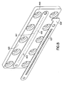
- Opening 637 of spacer plate 635 can be elongated into a slot shape as depicted in FIG. 7 having a width sufficient to expose the surface of orifices 641.
- a plurality of openings 537' is shown, each opening 537' being of sufficient diameter to expose the surface of orifice plate 630 surrounding orifices 641.
- Opening 537' having a diameter of approximately 0.052 inches (1.3 mm) is acceptable; other acceptable diameters of opening 537' can be in the range of about 0.010 to about 0.080 inches (0.25 to 2 mm).
- CP/OP 640 comprising chamber plate 625 and orifice plate 630 is depicted.
- Orifice plate 630 is shown with a plurality of orifices 641 formed therethrough wherein the plurality of orifices 641 are provided in orifice groups 642.
- orifices 641 of orifice group 642 can be formed in the shape of a hexagon, with one orifice at each vertex and a seventh in the middle. Of course, other arrangements are acceptable.
- Each orifice group can be formed with one to fifteen and even more orifices per group.
- Orifice plate 630 is depicted as having a plurality of groups of orifices 641, preferably between twenty and forty groups of orifices.
- FIG. 7 further depicts a spacer plate 635' having a single opening 637' formed therethrough in accordance with the present invention.
- FIG. 8 depicts a spacer plate 535' having a plurality of openings 537' formed therethrough in accordance with the present invention.
Landscapes
- Engineering & Computer Science (AREA)
- Manufacturing & Machinery (AREA)
- Particle Formation And Scattering Control In Inkjet Printers (AREA)
- Application Of Or Painting With Fluid Materials (AREA)
- Non-Metallic Protective Coatings For Printed Circuits (AREA)
- Formation And Processing Of Food Products (AREA)
Claims (11)
- Verfahren zum Beschichten einer Düsenplatte mit einem Material, das für ein ausgewähltes Material nichtnetzend ist, wobei das Verfahren Folgendes aufweist:Bereitstellen einer Platte, in der wenigstens eine Öffnung, die durch Öffnungswände definiert ist, definiert ist, wobei die Platte eine Vorderseite aufweist, und Bereitstellen einer Transferfläche, die aus nichtnetzendem Material gebildet ist, gekennzeichnet durch:Positionieren der Transferfläche neben der Platte, wobei sich zwischen der Transferfläche und der Platte ein Abstandshalter befindet, wobei der Abstandshalter so beschaffen ist, dass er einen offenen Raum für eine strömungsmäßige Verbindung zwischen der Transferfläche und der Fläche der Platte neben der Öffnung bildet;Erwärmen der Transferfläche auf eine Temperatur, die zu einem Verdampfen des nichtnetzenden Materials führt, woraufhin man das verdampfte nichtnetzende Material die Fläche der Platte neben der Öffnung beschichten lässt, wobei die Transferfläche, der Abstandshalter und die Platte dafür konstruiert und angeordnet sind und auf eine effektive Temperatur erwärmt werden, um die Fläche der Platte neben - und im Wesentlichen bis zum Rand - der Öffnung, aber im Wesentlichen nicht die Fläche der Öffnungswände zu beschichten.
- Verfahren nach Anspruch 1, wobei die Transferfläche durch Aufsprühen einer Zusammensetzung, die das nichtnetzende Material umfasst, auf eine Fläche eines Transferblocks gebildet wird.
- Verfahren nach Anspruch 1 oder 2, wobei die Düsenplatte dafür bemessen und konfiguriert ist, um als die Düsenplatte für einen Tintenstrahldruckkopf zu fungieren.
- Verfahren nach einem der vorangehenden Ansprüche, wobei die wenigstens eine Öffnung einen kleineren Durchmesser als ungefähr 0,024 Inch (0,6 mm) und bevorzugt einen Durchmesser von etwa 0,001 bis 0,024 Inch (0,025 bis 0,6 mm) aufweist.
- Verfahren nach einem der vorangehenden Ansprüche, wobei das nichtnetzende Material nichtnetzend für Materialien auf Wasserbasis ist oder wobei das nichtnetzende Material nichtnetzend für Materialien auf Ölbasis ist.
- Verfahren nach einem der vorangehenden Ansprüche, wobei das nichtnetzende Material PTFE umfasst und/oder wobei das nichtnetzende Material an der Transferfläche des nichtnetzenden Materials ein Schmierstoff auf Teflonbasis ist, der im Wesentlichen frei von Harzen ist.
- Verfahren nach einem der vorangehenden Ansprüche, wobei das Erwärmen auf über 400°F (204°C) erfolgt und bevorzugt im Bereich von 500 °F bis 650°F (260°C - 343°C) erfolgt.
- Verfahren nach einem der vorangehenden Ansprüche, wobei die Platte mehrere Öffnungen aufweist und der Abstandshalter die Form einer Platte hat, die einen länglichen Schlitz aufweist, der den offenen Raum definiert, und wobei der Schlitz, der in der Abstandshalterplatte ausgebildet ist, länglich ist, um die in der Düsenplatte ausgebildeten Öffnungen für die Transferfläche zugänglich zu machen, und wobei der Abstandshalter vorzugsweise die Form einer Platte hat, die 0,0005 bis 0,031 Inch (25 - 250 µm) dick ist und durch die hindurch wenigstens eine Öffnung ausgebildet ist, um den offenen Raum zu definieren.
- Verfahren nach einem der vorangehenden Ansprüche, wobei die Düsenplatte Gruppen mehrerer Öffnungen aufweist und der Abstandshalter die Form einer Platte hat, durch die hindurch eine Öffnung ausgebildet ist, die jeder Gruppe von Öffnungen entspricht, und wobei die Platte vorzugsweise wenigstens eine Gruppierung von ungefähr sieben Öffnungen enthält, die in einem Sechseck angeordnet sind, wobei eine Öffnung in der Mitte der Gruppierung angeordnet ist, und wobei des Weiteren die Platte vorzugsweise eine Reihe von etwa zwanzig bis vierzig der Gruppen aus ungefähr sieben Öffnungen enthält.
- Verfahren nach Anspruch 9, wobei die in der Abstandshalterplatte ausgebildete Öffnung einen Kreisdurchmesser von ungefähr 0,052 Inch (0,13 mm) hat und/oder wobei die Platte Öffnungen in einem Abstand von 72 - 140 Öffnungen je Inch (2,8 - 5,6 je mm) enthält.
- Verfahren nach einem der vorangehenden Ansprüche, wobei das nichtnetzende Material auf eine Dicke von 0,00004 bis 0,001 Inch (1 - 25 µm) aufbeschichtet wird.
Applications Claiming Priority (2)
| Application Number | Priority Date | Filing Date | Title |
|---|---|---|---|
| US10/280,194 US6592940B1 (en) | 2001-09-17 | 2002-10-25 | Method for coating an orifice plate |
| US280194 | 2002-10-25 |
Publications (2)
| Publication Number | Publication Date |
|---|---|
| EP1413440A1 EP1413440A1 (de) | 2004-04-28 |
| EP1413440B1 true EP1413440B1 (de) | 2007-07-18 |
Family
ID=32069367
Family Applications (1)
| Application Number | Title | Priority Date | Filing Date |
|---|---|---|---|
| EP03256463A Expired - Lifetime EP1413440B1 (de) | 2002-10-25 | 2003-10-14 | Verfahren zum Beschichten einer Düsenplatte |
Country Status (7)
| Country | Link |
|---|---|
| US (2) | US6592940B1 (de) |
| EP (1) | EP1413440B1 (de) |
| JP (1) | JP4354777B2 (de) |
| AT (1) | ATE367269T1 (de) |
| CA (1) | CA2444946C (de) |
| DE (1) | DE60314959T2 (de) |
| IL (1) | IL158560A0 (de) |
Families Citing this family (2)
| Publication number | Priority date | Publication date | Assignee | Title |
|---|---|---|---|---|
| US7118189B2 (en) * | 2004-05-28 | 2006-10-10 | Videojet Technologies Inc. | Autopurge printing system |
| JP5326728B2 (ja) * | 2009-03-26 | 2013-10-30 | セイコーエプソン株式会社 | 液体噴射装置 |
Family Cites Families (14)
| Publication number | Priority date | Publication date | Assignee | Title |
|---|---|---|---|---|
| US4343013A (en) * | 1980-10-14 | 1982-08-03 | Ncr Corporation | Nozzle plate for ink jet print head |
| US4364054A (en) * | 1981-03-02 | 1982-12-14 | Exxon Research And Engineering Co. | Method and apparatus for fluid jet printing |
| JP2614270B2 (ja) * | 1988-05-18 | 1997-05-28 | キヤノン株式会社 | インクジェット記録ヘッドの表面処理方法 |
| JP3009049B2 (ja) * | 1989-03-24 | 2000-02-14 | キヤノン株式会社 | インクジェット記録ヘッド、インクジェット記録ヘッドの表面処理方法、及びインクジェット記録装置 |
| US5212496A (en) * | 1990-09-28 | 1993-05-18 | Xerox Corporation | Coated ink jet printhead |
| JP3160908B2 (ja) * | 1991-02-04 | 2001-04-25 | セイコーエプソン株式会社 | インクジェット記録ヘッド及びその製造方法 |
| US5434606A (en) * | 1991-07-02 | 1995-07-18 | Hewlett-Packard Corporation | Orifice plate for an ink-jet pen |
| JP2975190B2 (ja) * | 1991-10-29 | 1999-11-10 | キヤノン株式会社 | インクジェット記録ヘッド |
| JPH05116325A (ja) * | 1991-10-30 | 1993-05-14 | Canon Inc | インクジエツト記録ヘツドの製造方法 |
| JP3196796B2 (ja) * | 1992-06-24 | 2001-08-06 | セイコーエプソン株式会社 | インクジェット記録ヘッドのノズル形成方法 |
| JPH116075A (ja) | 1997-06-16 | 1999-01-12 | Yokogawa Electric Corp | インクジェットヘッド及び製造方法 |
| US6050506A (en) * | 1998-02-13 | 2000-04-18 | Applied Materials, Inc. | Pattern of apertures in a showerhead for chemical vapor deposition |
| US6447984B1 (en) * | 1999-02-10 | 2002-09-10 | Canon Kabushiki Kaisha | Liquid discharge head, method of manufacture therefor and liquid discharge recording apparatus |
| JP2001246753A (ja) | 2000-03-02 | 2001-09-11 | Casio Comput Co Ltd | インクジェットプリンタヘッドとその製造方法 |
-
2002
- 2002-10-25 US US10/280,194 patent/US6592940B1/en not_active Expired - Fee Related
-
2003
- 2003-05-14 US US10/438,677 patent/US20030207081A1/en not_active Abandoned
- 2003-10-14 EP EP03256463A patent/EP1413440B1/de not_active Expired - Lifetime
- 2003-10-14 DE DE60314959T patent/DE60314959T2/de not_active Expired - Lifetime
- 2003-10-14 AT AT03256463T patent/ATE367269T1/de active
- 2003-10-15 CA CA002444946A patent/CA2444946C/en not_active Expired - Fee Related
- 2003-10-23 IL IL15856003A patent/IL158560A0/xx active IP Right Grant
- 2003-10-27 JP JP2003365829A patent/JP4354777B2/ja not_active Expired - Fee Related
Also Published As
| Publication number | Publication date |
|---|---|
| EP1413440A1 (de) | 2004-04-28 |
| US20030207081A1 (en) | 2003-11-06 |
| JP2004142466A (ja) | 2004-05-20 |
| JP4354777B2 (ja) | 2009-10-28 |
| IL158560A0 (en) | 2004-05-12 |
| DE60314959T2 (de) | 2008-04-03 |
| US6592940B1 (en) | 2003-07-15 |
| ATE367269T1 (de) | 2007-08-15 |
| CA2444946C (en) | 2008-06-17 |
| DE60314959D1 (de) | 2007-08-30 |
| CA2444946A1 (en) | 2004-04-25 |
Similar Documents
| Publication | Publication Date | Title |
|---|---|---|
| KR100439392B1 (ko) | 잉크젯프린터용프린트헤드와그제조방법및동작방법 | |
| US6254219B1 (en) | Inkjet printhead orifice plate having related orifices | |
| EP0629504B1 (de) | Düsenplatte für Tintenstrahldrucker | |
| US6371596B1 (en) | Asymmetric ink emitting orifices for improved inkjet drop formation | |
| US5255017A (en) | Three dimensional nozzle orifice plates | |
| EP0521697A2 (de) | Tintenstrahldruckersdüsenöffnungsplatte | |
| US6254215B1 (en) | Ink jet printing head and method for producing the same | |
| CN102202797A (zh) | 成形喷嘴出口 | |
| CA1302161C (en) | Nozzle plate geometry for ink jet pens and method of manufacture | |
| EP1566274A3 (de) | Verfahren zur Herstellung von Ausstosskammern für unterschiedliche Tropfengewichte auf einem einzigen Druckkopf | |
| JP2012086561A (ja) | 金属で被覆されたポリイミド開口プレートおよびその作製方法 | |
| CA2134341A1 (en) | Method of forming an orifice array for a high density ink jet printhead | |
| US6155675A (en) | Printhead structure and method for producing the same | |
| CA2401465C (en) | Method for coating an orifice plate | |
| KR20120129817A (ko) | 잉크젯 애플리케이션에 있어 ald/cvd 기술에 의한 멀티-스케일 조도를 통하여 초내오염성을 강화하고 접착력을 감소시키는 방법 | |
| EP1413440B1 (de) | Verfahren zum Beschichten einer Düsenplatte | |
| EP1205308A3 (de) | Korrekturverfahren für kontinuierlichen Tintenstrahldrucker | |
| JPH07329303A (ja) | インクジェットヘッドの表面処理方法 | |
| US20060274116A1 (en) | Ink-jet assembly coatings and related methods | |
| JPH0985956A (ja) | インクジェットノズルの形成方法 | |
| JPH0577415A (ja) | インクジエツトヘツド | |
| JPH09136416A (ja) | インクジェット記録ヘッド及びその製造方法 | |
| JPH11157077A (ja) | 薄膜プリントヘッド | |
| JPH08224878A (ja) | インク・ジェット印刷用のノズル・プレート | |
| JP3661350B2 (ja) | 静電吸引型マルチノズルインクジェットヘッド及びその製造方法 |
Legal Events
| Date | Code | Title | Description |
|---|---|---|---|
| PUAI | Public reference made under article 153(3) epc to a published international application that has entered the european phase |
Free format text: ORIGINAL CODE: 0009012 |
|
| AK | Designated contracting states |
Kind code of ref document: A1 Designated state(s): AT BE BG CH CY CZ DE DK EE ES FI FR GB GR HU IE IT LI LU MC NL PT RO SE SI SK TR |
|
| AX | Request for extension of the european patent |
Extension state: AL LT LV MK |
|
| 17P | Request for examination filed |
Effective date: 20041015 |
|
| AKX | Designation fees paid |
Designated state(s): AT DE FR GB IT |
|
| GRAP | Despatch of communication of intention to grant a patent |
Free format text: ORIGINAL CODE: EPIDOSNIGR1 |
|
| GRAS | Grant fee paid |
Free format text: ORIGINAL CODE: EPIDOSNIGR3 |
|
| GRAA | (expected) grant |
Free format text: ORIGINAL CODE: 0009210 |
|
| AK | Designated contracting states |
Kind code of ref document: B1 Designated state(s): AT DE FR GB IT |
|
| REG | Reference to a national code |
Ref country code: GB Ref legal event code: FG4D |
|
| REF | Corresponds to: |
Ref document number: 60314959 Country of ref document: DE Date of ref document: 20070830 Kind code of ref document: P |
|
| ET | Fr: translation filed | ||
| PLBE | No opposition filed within time limit |
Free format text: ORIGINAL CODE: 0009261 |
|
| STAA | Information on the status of an ep patent application or granted ep patent |
Free format text: STATUS: NO OPPOSITION FILED WITHIN TIME LIMIT |
|
| 26N | No opposition filed |
Effective date: 20080421 |
|
| PGFP | Annual fee paid to national office [announced via postgrant information from national office to epo] |
Ref country code: AT Payment date: 20100921 Year of fee payment: 8 |
|
| REG | Reference to a national code |
Ref country code: AT Ref legal event code: MM01 Ref document number: 367269 Country of ref document: AT Kind code of ref document: T Effective date: 20121014 |
|
| PG25 | Lapsed in a contracting state [announced via postgrant information from national office to epo] |
Ref country code: AT Free format text: LAPSE BECAUSE OF NON-PAYMENT OF DUE FEES Effective date: 20121014 |
|
| PGFP | Annual fee paid to national office [announced via postgrant information from national office to epo] |
Ref country code: FR Payment date: 20141017 Year of fee payment: 12 Ref country code: DE Payment date: 20141029 Year of fee payment: 12 Ref country code: GB Payment date: 20141027 Year of fee payment: 12 |
|
| PGFP | Annual fee paid to national office [announced via postgrant information from national office to epo] |
Ref country code: IT Payment date: 20141024 Year of fee payment: 12 |
|
| REG | Reference to a national code |
Ref country code: DE Ref legal event code: R119 Ref document number: 60314959 Country of ref document: DE |
|
| GBPC | Gb: european patent ceased through non-payment of renewal fee |
Effective date: 20151014 |
|
| PG25 | Lapsed in a contracting state [announced via postgrant information from national office to epo] |
Ref country code: IT Free format text: LAPSE BECAUSE OF NON-PAYMENT OF DUE FEES Effective date: 20151014 Ref country code: DE Free format text: LAPSE BECAUSE OF NON-PAYMENT OF DUE FEES Effective date: 20160503 Ref country code: GB Free format text: LAPSE BECAUSE OF NON-PAYMENT OF DUE FEES Effective date: 20151014 |
|
| REG | Reference to a national code |
Ref country code: FR Ref legal event code: ST Effective date: 20160630 |
|
| PG25 | Lapsed in a contracting state [announced via postgrant information from national office to epo] |
Ref country code: FR Free format text: LAPSE BECAUSE OF NON-PAYMENT OF DUE FEES Effective date: 20151102 |