EP1413190A1 - Machine a recolter - Google Patents
Machine a recolter Download PDFInfo
- Publication number
- EP1413190A1 EP1413190A1 EP03022016A EP03022016A EP1413190A1 EP 1413190 A1 EP1413190 A1 EP 1413190A1 EP 03022016 A EP03022016 A EP 03022016A EP 03022016 A EP03022016 A EP 03022016A EP 1413190 A1 EP1413190 A1 EP 1413190A1
- Authority
- EP
- European Patent Office
- Prior art keywords
- rotor
- machine according
- harvesting machine
- crop
- designed
- Prior art date
- Legal status (The legal status is an assumption and is not a legal conclusion. Google has not performed a legal analysis and makes no representation as to the accuracy of the status listed.)
- Withdrawn
Links
Images


Classifications
-
- A—HUMAN NECESSITIES
- A01—AGRICULTURE; FORESTRY; ANIMAL HUSBANDRY; HUNTING; TRAPPING; FISHING
- A01F—PROCESSING OF HARVESTED PRODUCE; HAY OR STRAW PRESSES; DEVICES FOR STORING AGRICULTURAL OR HORTICULTURAL PRODUCE
- A01F15/00—Baling presses for straw, hay or the like
- A01F15/08—Details
- A01F15/10—Feeding devices for the crop material e.g. precompression devices
- A01F15/106—Feeding devices for the crop material e.g. precompression devices for round balers
-
- A—HUMAN NECESSITIES
- A01—AGRICULTURE; FORESTRY; ANIMAL HUSBANDRY; HUNTING; TRAPPING; FISHING
- A01F—PROCESSING OF HARVESTED PRODUCE; HAY OR STRAW PRESSES; DEVICES FOR STORING AGRICULTURAL OR HORTICULTURAL PRODUCE
- A01F15/00—Baling presses for straw, hay or the like
- A01F15/08—Details
- A01F15/10—Feeding devices for the crop material e.g. precompression devices
- A01F2015/107—Means for withdrawing knives, rotor or walls of the feeding chamber in case of plugging or congestion
-
- A—HUMAN NECESSITIES
- A01—AGRICULTURE; FORESTRY; ANIMAL HUSBANDRY; HUNTING; TRAPPING; FISHING
- A01F—PROCESSING OF HARVESTED PRODUCE; HAY OR STRAW PRESSES; DEVICES FOR STORING AGRICULTURAL OR HORTICULTURAL PRODUCE
- A01F15/00—Baling presses for straw, hay or the like
- A01F15/08—Details
- A01F15/10—Feeding devices for the crop material e.g. precompression devices
- A01F2015/108—Cutting devices comprising cutter and counter-cutter
Definitions
- a round baler with a crop picker arranged below a press chamber and an overhead conveying knife shaft is known from WO 92/09191.
- a rotatably mounted intermediate roller, driven by the crop flow, is arranged between the crop rotor and the knife shaft, which is intended to support trouble-free conveying of the crop.
- a round baler with an overhead rotor-promoting pick-up rotor and an undershot knife shaft is also known from DE 43 08 646 A1.
- a further rotor driven by the crop is provided to promote a trouble-free crop flow.
- the other rotor rotates in the opposite direction to the pick-up rotor and in the same direction with the knife shaft.
- balers described above are associated with the disadvantage that no reliable crop flow can be guaranteed with the known arrangements for conveying crop material between the pick-up rotor and the baling chamber.
- the undercut conveying knife shafts require a relatively high drive energy. The undershot production continues to affect the quality of the peripheral surface of the bale in the baling chamber.
- the adjoining arrangement of the envelope or jacket surface of the cutting rotor and an envelope section of the pressing chamber, which at the same time defines the outer circumference of a round bale to be pressed, ensures reliable feeding of the crop to the pressing chamber.
- the envelopes can, for example, touch tangentially or be slightly spaced apart. However, you can also cut yourself slightly if necessary.
- An embodiment of the invention provides that at least the outer sections of the second rotor are driven.
- the second rotor can also consist only of the driven outer sections and have no middle section.
- the second rotor can only be set in rotation by the crop flow.
- the optional drive of at least the outer sections of the second rotor can take place, for example, by means of a chain or belt drive.
- the second rotor can optionally also have a hydraulic or pneumatic drive.
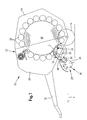
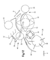
- a second rotor 36 of smaller diameter than the first rotor 30 Upstream of the first rotor 30 is a second rotor 36 of smaller diameter than the first rotor 30, the function and configuration of which will be explained in more detail with reference to the following figures.
- the actual crop pickup 28 Upstream of the second rotor 36 is the actual crop pickup 28, which essentially consists of a series of rotating pickup tines 38 which are fastened to a pickup rotor 34.
- the pickup tines 38 of the pickup rotor 34, the first rotor 30 and the second rotor 36 each rotate clockwise in the illustration shown, so that they each convey overhead.
- the direction of conveyance of the crop is indicated by an arrow F.
- the direction of advance of the harvesting machine 10 is also indicated by an arrow V.
- the envelope of the first rotor 30 designed as a cutting rotor and a circle adjacent to the inner envelope of the rollers 20 of the pressing chamber 18 border at least close to one another. If necessary, the envelopes can touch or cut slightly.
- the direction of rotation of a round bale to be formed is indicated by the arrow D.
- a guide 62 for example in the form of a guide plate or the like, is provided between the first rotor 30 and rollers 20 arranged above it, which prevents the round bale from pressing on the blades of the first rotor 30 from above and the material conveyance between the cutting device 32 and affect first rotor 30.
- These described rotors 30, 36 form the conveying device 8, which conveys oversight, ensures a trouble-free flow of material and are characterized by only a small required drive energy.
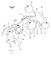
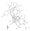
- the pick-up tines 38 of the crop pick-up 28 each sweep between U-shaped frame plates 64, which envelop the pick-up rotor 34 to the front and prevent longer crops from getting caught in the suspensions of the tines on the pick-up rotor 34.
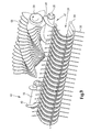
- the crop pickup 28 conveying overhead transfers the crop to the second rotor 36 also conveying overhead, which essentially consists of three sections.
- the second rotor 36 conveying the crop overhead transfers it to the first rotor 30, which has a significantly smaller working width than the second rotor 36.
- the first rotor 30 cuts the crop and then conveys it into the baling chamber (not shown).
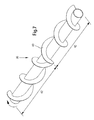
- Four drivers 66 of the first rotor 30, each with a curved contour, are each slightly offset from one another, so that overall a spiral outer contour of the driver edges is created. This spiral contour ensures an easier cut, since not all drivers pass the knives of the cutting device 32 at the same time, but an offset cut is produced.
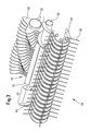
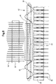
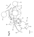
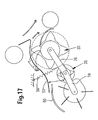
- FIG. 8 shows a further alternative embodiment of the conveyor device according to the invention, in which the second rotor 36 consists of at least two separate parts.
- the two outer sections 42 are provided with the cross-conveyor devices already explained above in the form of the screws 40 and are each actively driven.
- the middle section 44 is provided with the carrier webs 46 already described and does not have its own drive, but is set in rotation by the crop.
- the axes of rotation of the outer sections 42 and of the middle section 44 are preferably aligned with one another, as shown in FIG. 8.
- the outer sections 42 and the middle section 44 can be arranged on a common shaft or axis.
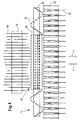
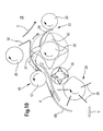
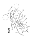
- the crop flow is also guided between two rotors 30 and 36 by means of a guide device 48; however, compression or guidance does not take place as a result of an adjustment of the guide device 48, but rather in that the second rotor 36 is movable transversely to the material flow and acted upon by a spring force.
- the crop pickup 28 is mounted such that it can be pivoted vertically about the axis of rotation of the second rotor 36 by means of arms 74 and the second rotor 36 can be moved in height about the axis of rotation of the first rotor 30 by means of arms 76. It is obvious that, due to the pivoting movement of the arms 74, 76, the second rotor 36 and the crop pickup 28 not only execute a movement directed transversely to the crop flow, but also a movement directed along the crop flow. Even if it is not shown, this longitudinal movement is made possible by the fact that the crop receiver 28 is carried in a floating manner and can also move along the crop flow direction.
Landscapes
- Life Sciences & Earth Sciences (AREA)
- Environmental Sciences (AREA)
- Harvesting Machines For Specific Crops (AREA)
Applications Claiming Priority (2)
| Application Number | Priority Date | Filing Date | Title |
|---|---|---|---|
| DE2002149595 DE10249595A1 (de) | 2002-10-24 | 2002-10-24 | Erntebergungsmaschine |
| DE10249595 | 2002-10-24 |
Publications (1)
| Publication Number | Publication Date |
|---|---|
| EP1413190A1 true EP1413190A1 (fr) | 2004-04-28 |
Family
ID=32049589
Family Applications (1)
| Application Number | Title | Priority Date | Filing Date |
|---|---|---|---|
| EP03022016A Withdrawn EP1413190A1 (fr) | 2002-10-24 | 2003-10-01 | Machine a recolter |
Country Status (2)
| Country | Link |
|---|---|
| EP (1) | EP1413190A1 (fr) |
| DE (1) | DE10249595A1 (fr) |
Cited By (5)
| Publication number | Priority date | Publication date | Assignee | Title |
|---|---|---|---|---|
| EP2156729A2 (fr) | 2008-08-19 | 2010-02-24 | Deere & Company | Dispositif d'assujettissement |
| US7877929B2 (en) | 2007-08-04 | 2011-02-01 | Rezzorb, Llc | Method and apparatus for reducing fertilizer use in agricultural operations |
| DE102012011574A1 (de) * | 2012-06-13 | 2013-12-19 | Claas Saulgau Gmbh | Erntevorrichtung zum Aufnehmen von Pflanzen |
| CN113906911A (zh) * | 2021-09-18 | 2022-01-11 | 威海和润实业有限公司 | 一种草料自动捆扎机及捆扎方法 |
| EP4059339A1 (fr) * | 2021-03-16 | 2022-09-21 | Pöttinger Landtechnik GmbH | Engin d'abattage-façonnage |
Families Citing this family (5)
| Publication number | Priority date | Publication date | Assignee | Title |
|---|---|---|---|---|
| DE102007053568A1 (de) | 2007-11-09 | 2009-05-14 | Alois Pöttinger Maschinenfabrik Gmbh | Erntemaschine |
| DE102011013243B4 (de) | 2011-03-07 | 2023-01-05 | Pöttinger Landtechnik Gmbh | Erntemaschine |
| DE102011013242B4 (de) | 2011-03-07 | 2023-07-27 | Pöttinger Landtechnik Gmbh | Ballenpresse |
| DE102014006179A1 (de) * | 2014-04-29 | 2015-10-29 | Alois Pöttinger Maschinenfabrik Gmbh | Erntemaschine |
| DE102016122347A1 (de) * | 2016-11-21 | 2018-05-24 | B. Strautmann & Söhne GmbH u. Co. KG | Ladevorrichtung an einer Erntemaschine |
Citations (8)
| Publication number | Priority date | Publication date | Assignee | Title |
|---|---|---|---|---|
| EP0286776A1 (fr) * | 1987-04-15 | 1988-10-19 | Deere & Company | Tête ramasseuse et machine à balles rondes |
| DE3811649C1 (en) * | 1988-04-07 | 1989-06-22 | Mengele Verwaltungen Gmbh, 8870 Guenzburg, De | Method for the uniform feeding of harvesting machines |
| EP0470356A2 (fr) * | 1990-08-10 | 1992-02-12 | Kverneland Geldrop B.V. | Presse pour des produits récoltés |
| EP0659332A1 (fr) * | 1993-12-20 | 1995-06-28 | D.B.D. S.p.A. | Appareil pour ramasser et couper le fourrage et la paille |
| DE19616999A1 (de) * | 1996-04-27 | 1997-10-30 | Deere & Co | Aufnehmer |
| EP1029441A2 (fr) * | 1999-02-17 | 2000-08-23 | Tigieffe - S.R.L. | Presse à balles pour les résidus de l'élagage |
| US20020011061A1 (en) * | 2000-05-12 | 2002-01-31 | Deere & Company, A Delaware Corporation. | Adjustable harvest material transport assembly for moving the material from a pick-up to a processor inlet |
| DE10063121A1 (de) * | 2000-12-18 | 2002-06-20 | Deere & Co | Rundballenpresse |
-
2002
- 2002-10-24 DE DE2002149595 patent/DE10249595A1/de not_active Withdrawn
-
2003
- 2003-10-01 EP EP03022016A patent/EP1413190A1/fr not_active Withdrawn
Patent Citations (8)
| Publication number | Priority date | Publication date | Assignee | Title |
|---|---|---|---|---|
| EP0286776A1 (fr) * | 1987-04-15 | 1988-10-19 | Deere & Company | Tête ramasseuse et machine à balles rondes |
| DE3811649C1 (en) * | 1988-04-07 | 1989-06-22 | Mengele Verwaltungen Gmbh, 8870 Guenzburg, De | Method for the uniform feeding of harvesting machines |
| EP0470356A2 (fr) * | 1990-08-10 | 1992-02-12 | Kverneland Geldrop B.V. | Presse pour des produits récoltés |
| EP0659332A1 (fr) * | 1993-12-20 | 1995-06-28 | D.B.D. S.p.A. | Appareil pour ramasser et couper le fourrage et la paille |
| DE19616999A1 (de) * | 1996-04-27 | 1997-10-30 | Deere & Co | Aufnehmer |
| EP1029441A2 (fr) * | 1999-02-17 | 2000-08-23 | Tigieffe - S.R.L. | Presse à balles pour les résidus de l'élagage |
| US20020011061A1 (en) * | 2000-05-12 | 2002-01-31 | Deere & Company, A Delaware Corporation. | Adjustable harvest material transport assembly for moving the material from a pick-up to a processor inlet |
| DE10063121A1 (de) * | 2000-12-18 | 2002-06-20 | Deere & Co | Rundballenpresse |
Cited By (10)
| Publication number | Priority date | Publication date | Assignee | Title |
|---|---|---|---|---|
| US7877929B2 (en) | 2007-08-04 | 2011-02-01 | Rezzorb, Llc | Method and apparatus for reducing fertilizer use in agricultural operations |
| EP2156729A2 (fr) | 2008-08-19 | 2010-02-24 | Deere & Company | Dispositif d'assujettissement |
| DE102008041331A1 (de) | 2008-08-19 | 2010-02-25 | Deere & Company, Moline | Niederhaltereinrichtung |
| EP2156729A3 (fr) * | 2008-08-19 | 2010-03-10 | Deere & Company | Dispositif d'assujettissement |
| US8186137B2 (en) | 2008-08-19 | 2012-05-29 | Deere & Company | Crop baffle arrangement |
| DE102012011574A1 (de) * | 2012-06-13 | 2013-12-19 | Claas Saulgau Gmbh | Erntevorrichtung zum Aufnehmen von Pflanzen |
| DE102012011574B4 (de) * | 2012-06-13 | 2015-02-05 | Claas Saulgau Gmbh | Erntevorrichtung zum Aufnehmen von Pflanzen |
| EP4059339A1 (fr) * | 2021-03-16 | 2022-09-21 | Pöttinger Landtechnik GmbH | Engin d'abattage-façonnage |
| CN113906911A (zh) * | 2021-09-18 | 2022-01-11 | 威海和润实业有限公司 | 一种草料自动捆扎机及捆扎方法 |
| CN113906911B (zh) * | 2021-09-18 | 2022-12-02 | 威海和润实业有限公司 | 一种草料自动捆扎机及捆扎方法 |
Also Published As
| Publication number | Publication date |
|---|---|
| DE10249595A1 (de) | 2004-06-24 |
Similar Documents
| Publication | Publication Date | Title |
|---|---|---|
| EP0803184B1 (fr) | Ramasseur | |
| EP1305998B1 (fr) | Dispositif d'introduction et de cueillage | |
| EP1161857B1 (fr) | Dispositif d'introduction et de cueillage | |
| EP1797753B1 (fr) | Faucheuse-hâcheuse | |
| DE102015206845A1 (de) | Schneidwerk zur Ganzpflanzenernte | |
| EP1428423B1 (fr) | Dispositif de prise et de cueillette | |
| EP1424001B1 (fr) | Presse à balles | |
| EP1413190A1 (fr) | Machine a recolter | |
| WO2000001215A1 (fr) | Presse-ramasseuse pour produit de recolte agricole | |
| EP1417879A1 (fr) | Ramasseur pour produits agricoles | |
| DE102016107861A1 (de) | Erntemaschine mit einer Erntegutaufnahmevorrichtung | |
| EP1495664A1 (fr) | Machine pour faucher des plantes à tiges | |
| DE2062945C3 (de) | Maiserntegerät | |
| AT392194B (de) | Maschine zum ernten von mais od. dgl. stengelartigem erntegut | |
| DE102006027078A1 (de) | Gutaufnehmer | |
| DE19750954A1 (de) | Aufnahmeeinrichtung einer landwirtschaftlichen Erntemaschine | |
| DE102018123990A1 (de) | Betätigungshebel für eine Erntemaschine mit einer Schneidvorrichtung | |
| DE2900554C2 (fr) | ||
| EP3593623B1 (fr) | Machine de récolte doté d'un dispositif de ramassage de récolte | |
| EP1413191A1 (fr) | Presse | |
| EP4074162B1 (fr) | Presse à balles rondes pourvue de rouleau de démarrage et d'élément de déviation pouvant être dévié élastiquement | |
| EP3721696B1 (fr) | Machine de récolte dotée d'un dispositif de coupe | |
| EP3569056A1 (fr) | Dispositif de guidage du moyen de pression et presse | |
| DE10026495A1 (de) | Erntegerät | |
| DE3929349C2 (fr) |
Legal Events
| Date | Code | Title | Description |
|---|---|---|---|
| PUAI | Public reference made under article 153(3) epc to a published international application that has entered the european phase |
Free format text: ORIGINAL CODE: 0009012 |
|
| AK | Designated contracting states |
Kind code of ref document: A1 Designated state(s): AT BE BG CH CY CZ DE DK EE ES FI FR GB GR HU IE IT LI LU MC NL PT RO SE SI SK TR |
|
| AX | Request for extension of the european patent |
Extension state: AL LT LV MK |
|
| 17P | Request for examination filed |
Effective date: 20041028 |
|
| AKX | Designation fees paid |
Designated state(s): AT BE BG CH CY CZ DE DK EE ES FI FR GB GR HU IE IT LI LU MC NL PT RO SE SI SK TR |
|
| 17Q | First examination report despatched |
Effective date: 20060803 |
|
| STAA | Information on the status of an ep patent application or granted ep patent |
Free format text: STATUS: THE APPLICATION IS DEEMED TO BE WITHDRAWN |
|
| 18D | Application deemed to be withdrawn |
Effective date: 20070214 |