EP1412603B2 - Getriebe-antriebseinheit mit drehzahlerfassung - Google Patents
Getriebe-antriebseinheit mit drehzahlerfassung Download PDFInfo
- Publication number
- EP1412603B2 EP1412603B2 EP02754324A EP02754324A EP1412603B2 EP 1412603 B2 EP1412603 B2 EP 1412603B2 EP 02754324 A EP02754324 A EP 02754324A EP 02754324 A EP02754324 A EP 02754324A EP 1412603 B2 EP1412603 B2 EP 1412603B2
- Authority
- EP
- European Patent Office
- Prior art keywords
- sensor
- wheel
- drive unit
- gearbox
- armature shaft
- Prior art date
- Legal status (The legal status is an assumption and is not a legal conclusion. Google has not performed a legal analysis and makes no representation as to the accuracy of the status listed.)
- Expired - Lifetime
Links
- 238000005259 measurement Methods 0.000 title description 4
- 239000000463 material Substances 0.000 claims description 2
- 230000005540 biological transmission Effects 0.000 description 18
- 230000005291 magnetic effect Effects 0.000 description 11
- 238000001514 detection method Methods 0.000 description 7
- 238000011156 evaluation Methods 0.000 description 3
- 230000035945 sensitivity Effects 0.000 description 3
- 230000006978 adaptation Effects 0.000 description 2
- 230000008901 benefit Effects 0.000 description 2
- 239000004519 grease Substances 0.000 description 2
- 230000005405 multipole Effects 0.000 description 2
- 230000035515 penetration Effects 0.000 description 2
- 229910000859 α-Fe Inorganic materials 0.000 description 2
- 230000001133 acceleration Effects 0.000 description 1
- 230000009286 beneficial effect Effects 0.000 description 1
- 230000008859 change Effects 0.000 description 1
- 230000008878 coupling Effects 0.000 description 1
- 238000010168 coupling process Methods 0.000 description 1
- 238000005859 coupling reaction Methods 0.000 description 1
- 230000001419 dependent effect Effects 0.000 description 1
- 230000002349 favourable effect Effects 0.000 description 1
- 230000001939 inductive effect Effects 0.000 description 1
- 238000009434 installation Methods 0.000 description 1
- 230000005415 magnetization Effects 0.000 description 1
- 238000004519 manufacturing process Methods 0.000 description 1
- 238000000465 moulding Methods 0.000 description 1
- 230000003287 optical effect Effects 0.000 description 1
- 230000009467 reduction Effects 0.000 description 1
- 238000007789 sealing Methods 0.000 description 1
- 230000007704 transition Effects 0.000 description 1
Images

Classifications
-
- F—MECHANICAL ENGINEERING; LIGHTING; HEATING; WEAPONS; BLASTING
- F16—ENGINEERING ELEMENTS AND UNITS; GENERAL MEASURES FOR PRODUCING AND MAINTAINING EFFECTIVE FUNCTIONING OF MACHINES OR INSTALLATIONS; THERMAL INSULATION IN GENERAL
- F16H—GEARING
- F16H1/00—Toothed gearings for conveying rotary motion
- F16H1/02—Toothed gearings for conveying rotary motion without gears having orbital motion
- F16H1/04—Toothed gearings for conveying rotary motion without gears having orbital motion involving only two intermeshing members
-
- G—PHYSICS
- G01—MEASURING; TESTING
- G01D—MEASURING NOT SPECIALLY ADAPTED FOR A SPECIFIC VARIABLE; ARRANGEMENTS FOR MEASURING TWO OR MORE VARIABLES NOT COVERED IN A SINGLE OTHER SUBCLASS; TARIFF METERING APPARATUS; MEASURING OR TESTING NOT OTHERWISE PROVIDED FOR
- G01D5/00—Mechanical means for transferring the output of a sensing member; Means for converting the output of a sensing member to another variable where the form or nature of the sensing member does not constrain the means for converting; Transducers not specially adapted for a specific variable
- G01D5/12—Mechanical means for transferring the output of a sensing member; Means for converting the output of a sensing member to another variable where the form or nature of the sensing member does not constrain the means for converting; Transducers not specially adapted for a specific variable using electric or magnetic means
- G01D5/14—Mechanical means for transferring the output of a sensing member; Means for converting the output of a sensing member to another variable where the form or nature of the sensing member does not constrain the means for converting; Transducers not specially adapted for a specific variable using electric or magnetic means influencing the magnitude of a current or voltage
- G01D5/142—Mechanical means for transferring the output of a sensing member; Means for converting the output of a sensing member to another variable where the form or nature of the sensing member does not constrain the means for converting; Transducers not specially adapted for a specific variable using electric or magnetic means influencing the magnitude of a current or voltage using Hall-effect devices
- G01D5/145—Mechanical means for transferring the output of a sensing member; Means for converting the output of a sensing member to another variable where the form or nature of the sensing member does not constrain the means for converting; Transducers not specially adapted for a specific variable using electric or magnetic means influencing the magnitude of a current or voltage using Hall-effect devices influenced by the relative movement between the Hall device and magnetic fields
-
- B—PERFORMING OPERATIONS; TRANSPORTING
- B60—VEHICLES IN GENERAL
- B60R—VEHICLES, VEHICLE FITTINGS, OR VEHICLE PARTS, NOT OTHERWISE PROVIDED FOR
- B60R1/00—Optical viewing arrangements; Real-time viewing arrangements for drivers or passengers using optical image capturing systems, e.g. cameras or video systems specially adapted for use in or on vehicles
- B60R1/02—Rear-view mirror arrangements
- B60R1/06—Rear-view mirror arrangements mounted on vehicle exterior
- B60R1/062—Rear-view mirror arrangements mounted on vehicle exterior with remote control for adjusting position
- B60R1/07—Rear-view mirror arrangements mounted on vehicle exterior with remote control for adjusting position by electrically powered actuators
- B60R1/074—Rear-view mirror arrangements mounted on vehicle exterior with remote control for adjusting position by electrically powered actuators for retracting the mirror arrangements to a non-use position alongside the vehicle
-
- F—MECHANICAL ENGINEERING; LIGHTING; HEATING; WEAPONS; BLASTING
- F16—ENGINEERING ELEMENTS AND UNITS; GENERAL MEASURES FOR PRODUCING AND MAINTAINING EFFECTIVE FUNCTIONING OF MACHINES OR INSTALLATIONS; THERMAL INSULATION IN GENERAL
- F16H—GEARING
- F16H59/00—Control inputs to control units of change-speed-, or reversing-gearings for conveying rotary motion
- F16H59/36—Inputs being a function of speed
- F16H59/38—Inputs being a function of speed of gearing elements
-
- G—PHYSICS
- G01—MEASURING; TESTING
- G01P—MEASURING LINEAR OR ANGULAR SPEED, ACCELERATION, DECELERATION, OR SHOCK; INDICATING PRESENCE, ABSENCE, OR DIRECTION, OF MOVEMENT
- G01P3/00—Measuring linear or angular speed; Measuring differences of linear or angular speeds
- G01P3/42—Devices characterised by the use of electric or magnetic means
- G01P3/44—Devices characterised by the use of electric or magnetic means for measuring angular speed
- G01P3/48—Devices characterised by the use of electric or magnetic means for measuring angular speed by measuring frequency of generated current or voltage
- G01P3/481—Devices characterised by the use of electric or magnetic means for measuring angular speed by measuring frequency of generated current or voltage of pulse signals
- G01P3/487—Devices characterised by the use of electric or magnetic means for measuring angular speed by measuring frequency of generated current or voltage of pulse signals delivered by rotating magnets
-
- H—ELECTRICITY
- H02—GENERATION; CONVERSION OR DISTRIBUTION OF ELECTRIC POWER
- H02K—DYNAMO-ELECTRIC MACHINES
- H02K11/00—Structural association of dynamo-electric machines with electric components or with devices for shielding, monitoring or protection
- H02K11/20—Structural association of dynamo-electric machines with electric components or with devices for shielding, monitoring or protection for measuring, monitoring, testing, protecting or switching
- H02K11/21—Devices for sensing speed or position, or actuated thereby
- H02K11/215—Magnetic effect devices, e.g. Hall-effect or magneto-resistive elements
-
- E—FIXED CONSTRUCTIONS
- E05—LOCKS; KEYS; WINDOW OR DOOR FITTINGS; SAFES
- E05F—DEVICES FOR MOVING WINGS INTO OPEN OR CLOSED POSITION; CHECKS FOR WINGS; WING FITTINGS NOT OTHERWISE PROVIDED FOR, CONCERNED WITH THE FUNCTIONING OF THE WING
- E05F15/00—Power-operated mechanisms for wings
- E05F15/60—Power-operated mechanisms for wings using electrical actuators
- E05F15/603—Power-operated mechanisms for wings using electrical actuators using rotary electromotors
-
- F—MECHANICAL ENGINEERING; LIGHTING; HEATING; WEAPONS; BLASTING
- F16—ENGINEERING ELEMENTS AND UNITS; GENERAL MEASURES FOR PRODUCING AND MAINTAINING EFFECTIVE FUNCTIONING OF MACHINES OR INSTALLATIONS; THERMAL INSULATION IN GENERAL
- F16H—GEARING
- F16H1/00—Toothed gearings for conveying rotary motion
- F16H1/02—Toothed gearings for conveying rotary motion without gears having orbital motion
- F16H1/04—Toothed gearings for conveying rotary motion without gears having orbital motion involving only two intermeshing members
- F16H1/12—Toothed gearings for conveying rotary motion without gears having orbital motion involving only two intermeshing members with non-parallel axes
- F16H1/16—Toothed gearings for conveying rotary motion without gears having orbital motion involving only two intermeshing members with non-parallel axes comprising worm and worm-wheel
-
- H—ELECTRICITY
- H02—GENERATION; CONVERSION OR DISTRIBUTION OF ELECTRIC POWER
- H02K—DYNAMO-ELECTRIC MACHINES
- H02K7/00—Arrangements for handling mechanical energy structurally associated with dynamo-electric machines, e.g. structural association with mechanical driving motors or auxiliary dynamo-electric machines
- H02K7/10—Structural association with clutches, brakes, gears, pulleys or mechanical starters
- H02K7/116—Structural association with clutches, brakes, gears, pulleys or mechanical starters with gears
- H02K7/1163—Structural association with clutches, brakes, gears, pulleys or mechanical starters with gears where at least two gears have non-parallel axes without having orbital motion
- H02K7/1166—Structural association with clutches, brakes, gears, pulleys or mechanical starters with gears where at least two gears have non-parallel axes without having orbital motion comprising worm and worm-wheel
-
- Y—GENERAL TAGGING OF NEW TECHNOLOGICAL DEVELOPMENTS; GENERAL TAGGING OF CROSS-SECTIONAL TECHNOLOGIES SPANNING OVER SEVERAL SECTIONS OF THE IPC; TECHNICAL SUBJECTS COVERED BY FORMER USPC CROSS-REFERENCE ART COLLECTIONS [XRACs] AND DIGESTS
- Y10—TECHNICAL SUBJECTS COVERED BY FORMER USPC
- Y10T—TECHNICAL SUBJECTS COVERED BY FORMER US CLASSIFICATION
- Y10T74/00—Machine element or mechanism
- Y10T74/19—Gearing
- Y10T74/19642—Directly cooperating gears
- Y10T74/19679—Spur
- Y10T74/19684—Motor and gearing
-
- Y—GENERAL TAGGING OF NEW TECHNOLOGICAL DEVELOPMENTS; GENERAL TAGGING OF CROSS-SECTIONAL TECHNOLOGIES SPANNING OVER SEVERAL SECTIONS OF THE IPC; TECHNICAL SUBJECTS COVERED BY FORMER USPC CROSS-REFERENCE ART COLLECTIONS [XRACs] AND DIGESTS
- Y10—TECHNICAL SUBJECTS COVERED BY FORMER USPC
- Y10T—TECHNICAL SUBJECTS COVERED BY FORMER US CLASSIFICATION
- Y10T74/00—Machine element or mechanism
- Y10T74/19—Gearing
- Y10T74/19642—Directly cooperating gears
- Y10T74/19698—Spiral
- Y10T74/19828—Worm
Definitions
- the invention relates to a transmission drive unit with speed detection, in particular for use in motor vehicles according to the preamble of the independent claims.
- a substantially pot-shaped motor housing includes a motor armature with an extended from the motor housing armature shaft. Between the motor housing and the gear housing, the armature shaft is mounted with a spherical bearing. Between the motor armature and the spherical bearing a collector and a ring magnet is arranged on the armature shaft. The ring magnet is alternately magnetized in its outer circumference in the north and south directions. The changing magnetic field is detected by two 90 ° offset Hall sensors and evaluated by a arranged on an electronic board control electronics.
- the electronics board protrudes into the motor housing up to the immediate vicinity of the ring magnet. This arrangement of the electronic board within the motor housing or in the area of the brush holder is very cumbersome and inflexible. In addition, the brush fire causes disturbances in the speed sensor.
- the DE 198 54 038 A1 disclosed an adjusting device, in which a ring magnet for speed detection is arranged on an armature shaft of the drive motor.
- the ring magnet is arranged axially movably on the armature shaft in order to also detect acceleration forces in the longitudinal direction of the armature shaft.
- the US 5,636,071 shows a reduction gear of an electrically adjustable rearview mirror, in which the torque of an electric motor is transmitted via a plurality of gear stages on a coupling element.
- the DE 19 749 009 A1 , the DE 3 426 988 A1 , the EP 0 932 025 A1 and the DE 19 743 129 A1 show motor-driven gear units, in which a sensor wheel with magnetic position sensor cooperates with a gear wheel.
- the device according to the invention with the features of the independent Ansprüchs has the advantage that the speed sensor can be arranged completely outside of the motor housing. This eliminates the considerable design effort to arrange the electronics board with the sensors located thereon within the motor housing.
- the arrangement of the electronic board in the region of the gear housing, the formats of the electronic board can be made smaller and simpler.
- the gear chamber can be easily sealed against the collector space, since the electronics board no longer protrudes into the collector space. Due to the free choice to arrange the sensor wheel at a suitable location on the drive or driven gear, the spatial position of the sensor can be optimally adapted to the respective housing of the transmission drive unit. Due to the spatial distance to the collector disturbing influences are prevented by this on the sensors.
- the freely selectable positioning of the sensor wheel along the drive or driven gear allows ideal space utilization and design of the transmission drive unit.
- the length of the armature shaft, and thus the entire transmission drive unit is reduced. This is of particular importance in the application for seat adjustment or the sunroof, since the available space is limited here.
- the drive wheel is designed as a screw arranged on the armature shaft.
- the sensor wheel designed as a worm wheel can then mesh directly with the worm. Depending on the desired sensitivity of the speed sensor while the translation to the sensor wheel (number of teeth) can be selected accordingly. If the sensor wheel engages in the worm on the side opposite the worm wheel, the armature shaft is additionally supported at this point.
- the sensor wheel is arranged on the side opposite the driven wheel side of the screw because thereby the sensor wheel at the same time supports the armature shaft.
- the armature shaft is usually stored firmly in the pole pot and in the transition region between the motor housing and the gear housing, for example by means of spherical bearings.
- the free end of the armature shaft in the transmission housing is supported for example by means of a bearing journal in order to prevent deflection of the armature shaft when an increased load torque occurs.
- a bearing journal in order to prevent deflection of the armature shaft when an increased load torque occurs.
- the molding of such a journal is on the one hand relatively expensive, on the other hand, such storage usually leads to vibrations with an undesirable noise.
- the worm gear is made very precisely in the engagement region of the output gear, the arrangement of the sensor wheel as a support gear on the opposite side causes a very precise and low-noise storage. As a result, a trouble-free meshing of the teeth of worm and driven gear is ensured and damage to the teeth or even skip derselbigen safely avoided.
- a magnet as a position sensor, since it can be easily attached to the sensor wheel, or the sensor wheel has material that can be magnetized in a simple manner.
- a two-pole magnet is particularly favorable, but also a multi-pole arrangement to increase the resolution of, speed measurement is easily produced.
- the attachment / magnetization of a two-pole magnet is preferred because this design is much cheaper than the production of a ring magnet.
- the position sensor is arranged on the free end face of the sensor wheel, this allows greater flexibility in the arrangement of the corresponding sensor systems.
- inductive, optical or magnetic sensors these are not limited to a radial arrangement-as with ring magnets on the armature shaft-but the sensors can be arranged directly along the free face of the sensor wheel, thereby substantially more space for the sensors is available.
- Hall sensors which can be arranged both radially and planar to the sensor wheel. This design is particularly beneficial for applications where high resolution speed sensing is not required (incremental systems).
- magnetoresistive elements as sensors is particularly advantageous for use in high-precision absolute angle measuring systems.
- the magnetoresistive element directly measures the orientation of the magnetic field, for example a magnetic dipole.
- a much higher resolution is achieved, which allows more precise adjustments, for example, for adjustment paths with high Ganautechniksan Kunststoffen.
- the magnetoresistive element can be arranged in a planar manner with respect to the end face of the sensor wheel having at least one magnetic dipole.
- the sensor system has a device with which the angular pitch of a sensor wheel revolution can be freely selected.
- This can be set arbitrarily with a structure, the number of edges that emits the sensor system during a sensor wheel revolution.
- the variable rotation angle division can be realized on the basis of the absolute rotation angle measurement by means of electronic circuit or by software. This allows an optimal adaptation of the resolution of the speed measurement to the specific application and can also be varied during operation.
- the electronic board can be completely inside the gear housing or an electronics housing and have a smaller, simpler format.
- the in the Figures 1 and 2 The device shown has an electric motor 12 with an armature shaft 14 on which a screw 18 is rotatably mounted as the drive wheel 16.
- the worm 18 meshes with a driven wheel 22 shaped as a worm wheel 20.
- An output gear 24 is integrally formed on the worm wheel 20 against which a torque can be tapped.
- To detect the engine speed - or the rotational speed - is a sensor wheel 26 via a toothing 28 in engagement with the worm wheel 20.
- Both the worm wheel 20 and the sensor wheel 26 rotate on two axes (worm wheel 30, sensor wheel 32), each rotatably in a non-illustrated housing 52 of the transmission drive unit 10 are arranged.
- FIG. 2 shows a section through the sensor wheel 26, wherein the axis 32 is fixed in the housing 52, not shown in detail (above in FIG. 2 ).
- the sensor wheel 26 has a free end face 34 on which a magnetic dipole 38 is magnetized as a position transmitter 36.
- the position sensor 36 directly opposite a sensor 42 is arranged on a circuit board 40, which in this embodiment is designed as a magnetoresistive element (GMR, AXR) 44.
- the sensor 42 is connected to an evaluation device 46 on the circuit board 40, which outputs a sequence of signal edges as an output signal of the speed detection.
- the magnetoresistive element (GMR, AXR) 44 can not only detect the reversal of a magnetic field, but also measure the absolute angle of rotation of the rotating magnetic dipole 38.
- the resolution of the speed signal is thereby arbitrarily adjustable by the angular pitch of the sensor wheel 26, that is, the number of signal edges per revolution, by means of the evaluation device 46 is set. This can be carried out within the evaluation device 46 both in terms of hardware by electronic circuits, as well as software.
- the sensitivity of the speed detection can be changed even in operation in the present embodiment. This allows a very simple adaptation of the transmission drive unit 10 to the respective application.
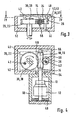
- FIGS. 3 and 4 show an embodiment of a transmission drive unit 10 according to the invention, in which the sensor wheel 26 serves to support the armature shaft 14.
- the transmission drive unit 10 has a motor 12 with a collector 13 and a surrounding motor housing 50, and a transmission housing 52, which includes the complete speed sensor system in addition to the transmission.
- the armature shaft 14 is fixedly mounted on the one hand in an armature bearing 48 at the bottom of the motor housing 50 and a ball bearing 54 in the region between the motor housing 50 and the gear housing 52.
- the free end 56 of the armature shaft 14 is at least radially additionally supported by the opposite arrangement of the sensor wheel 26 and the worm wheel 20.
- FIG. 4 dashed lines, an electronic circuit board 40 is shown, on which opposite the end face 34 of the sensor wheel 26 as a sensor 42, a Hall sensor 43 is arranged.
- the sensor wheel 26 is in this case made of plastic ferrite from plastic ferrite (at least partially), which is magnetized to a multi-pole ring magnet 37.
- the Hall sensor 43 arranged in the immediate vicinity of this ring magnet 37 detects incrementally the pole changes of the ring magnet 37. The resolution of the speed detection is thus given by the number of pole pairs of the ring magnet 37 and by the number of teeth of the sensor wheel 26.
- the output gear 22 has a position sensor 36, which is formed here as a simple magnetic dipole 38 on the front side of the output gear 22.
- the output gear 22 takes over the function of a sensor wheel 26, since on the circuit board 40 also a sensor 42 is arranged, which detects the rotation of the magnetic dipole 38. This is vivid in FIG. 3 to recognize.
- Out FIG. 4 It can be seen that the entire sensor system is located within the transmission housing 52. As a result, it is not necessary that the circuit board 40 extends into the motor housing 50 to the collector 13, as is usually the case with previous transmission drive units 10 with speed detection. Therefore, the transmission case 52 is sealed with respect to the motor housing 50, thereby preventing the penetration of grease of the transmission into the motor housing 50.
- the exact position of the sensor wheel 26 along the drive wheel 16, or the driven wheel 22 can be varied such that different engine designs are realized with optimum space utilization. Also, the number of teeth of the sensor wheel 26 can be selected to match the sensor to the corresponding requirements.
- the embodiment of the drive wheel 22 as a sensor wheel 26 or other combinations of individual features of the invention are further embodiments of the invention.
Abstract
Description
- Die Erfindung betrifft eine Getriebe- Antriebseinheit mit Drehzahlerfassung, insbesondere für die Verwendung im Kraftfahrzeug nach der Gattung der unabhängigen Ansprüche.
- Mit der
EP 0 865 148 A1 ist eine Motor-Getriebe-Antriebseinheit zum Verstellen von Ausstattungsteilen von Kraftfahrzeugen mit einem Kommutatormotor bekannt geworden. Dabei enthält ein im Wesentlichen topfförmiges Motorgehäuse einen Motoranker mit einer aus dem Motorgehäuse verlängerten Ankerwelle. Zwischen dem Motorgehäuse und dem Getriebegehäuse wird die Ankerwelle mit einem Kalottenlager gelagert. Zwischen dem Motoranker und dem Kalottenlager ist auf der Ankerwelle ein Kollektor und ein Ringmagnet angeordnet. Der Ringmagnet ist in seinem äußeren Umfang abwechselnd in Nord- und Südrichtung magnetisiert. Das sich ändernde Magnetfeld wird von zwei 90° versetzt zueinander angeordneten Hallsensoren erfasst und von einer auf einer Elektronikplatine angeordneten Steuerelektronik ausgewertet. Dabei ragt die Elektronikplatine in das Motorgehäuse bis zur unmittelbaren Nähe des Ringmagneten hinein. Diese Anordnung der Elektronikplatine innerhalb des Motorgehäuses oder im Bereich des Bürstenhalters ist sehr umständlich und unflexibel. Außerdem verursacht das Bürstenfeuer Störungen bei der Drehzahlsensorik. - Die
DE 198 54 038 A1 offenbarte eine Verstelleinrichtung, bei der auf einer Ankerwelle des Antriebsmotors ein Ringmagnet zur Drehzahlerfassung angeordnet ist. Der Ringmagnet ist axial beweglich auf der Ankerwelle angeordnet, um auch Beschleunigungskräfte in Längsrichtung der Ankerwelle zu erfassen. - Die
US 5,636,071 zeigt ein Untersetzungsgetriebe eines elektrisch verstellbaren Rückspiegels, bei dem das Drehmoment eines Elektromotors über mehrere Getriebestufen auf ein Kupplungselement übertragen wird. - Die
DE 19 749 009 A1 , dieDE 3 426 988 A1 , dieEP 0 932 025 A1 und dieDE 19 743 129 A1 zeigen motorisch angetriebene Getriebeeinheiten, bei denen ein Sensorrad mit magnetischem Positionsgeber mit einem Getrieberad zusammenwirkt. - Die erfindungsgemäße Vorrichtung mit den Merkmalen des unabhängigen Ansprüchs hat den Vorteil, dass die Drehzahlsensorik komplett außerhalb des Motorgehäuses angeordnet werden kann. Dadurch entfällt der erhebliche konstruktive Aufwand, die Elektronikplatine mit dem sich darauf befindenden Sensoren innerhalb des Motorgehäuses anzuordnen. Durch die Anordnung der Elektroplatine im Bereich des Getriebegehäuses können die Formate der Elektronikplatine kleiner und einfacher ausgeführt sein. Außerdem kann vorteilhafterweise der Getrieberaum einfach gegenüber dem Kollektorraum abgedichtet werden, da die Elektronikplatine nicht mehr in den Kollektorraum ragt.
Durch die freie Wahl, das Sensorrad an einer geeigneten Stelle am Antriebs- oder Abtriebsrad anzuordnen, kann die räumliche Lage der Sensorik optimal an das jeweilige Gehäuse der Getriebe-Antriebseinheit angepaßt werden. Durch die räumliche Entfernung zum Kollektor werden Störeinflüsse durch diesen auf die Sensorik verhindert. Die frei wählbare Positionierung des Sensorrads entlang des Antriebs- oder Abtriebsrads erlaubt eine ideale Raumausnutzung und Gestaltung der Getriebe-Antriebseinheit. Durch den Verzicht auf den Ringmagneten wird die Baulänge der Ankerwelle, und damit auch der gesamten Getriebe-Antriebseinheit verringert. Dies ist von besonderer Bedeutung bei der Anwendung zur Sitzverstellung oder beim Schiebedach, da hier der zu Verfügung stehende Bauraum begrenzt ist. - Das Antriebsrad ist als eine auf der Ankerwelle angeordnete Schnecke ausgeführt. Das als Schneckenrad ausgeführte Sensorrad kann dann direkt mit der Schnecke kämmen. Je nach gewünschter Empfindlichkeit der Drehzahlsensorik kann dabei die Übersetzung zum Sensorrad (Anzahl der Zähne) entsprechend gewählt werden. Greift das Sensorrad auf der dem Schneckenrad gegenüberliegenden Seite in die Schnecke, so wird die Ankerwelle an dieser Stelle zusätzlich abgestützt. Das Sensorrad ist an der dem Abtriebsrad gegenüberliegenden Seite der Schnecke angeordnet weil dadurch das Sensorrad gleichzeitig die Ankerwelle abstützt. Die Ankerwelle wird gewöhnlich im Poltopf und im Übergangsbereich zwischen Motorgehäuse und Getriebegehäuse beispielsweise mittels Kalottenlager fest gelagert. Das freie Ende der Ankerwelle im Getriebegehäuse wird beispielsweise mittels eines Lagerzapfen abgestützt, um ein Ausweichen der Ankerwelle beim Auftreten eines erhöhten Lastmoments zu verhindern. Das Anformen eines solchen Lagerzapfen ist einerseits relativ aufwendig, andererseits führt eine solche Lagerung meist zu Vibrationen mit einer unerwünschten Geräuschentwicklung. Da die Schneckenverzahnung im Eingriffsbereich des Abtriebsrad sehr genau gefertigt ist, bewirkt die Anordnung des Sensorrads als Stützzahnrad auf der gegenüberliegenden Seite eine sehr exakte und geräuscharme Lagerung. Dadurch wird ein störungsfreies Ineinandergreifen der Verzahnung von Schnecke und Abtriebsrad gewährleistet und eine Beschädigung der Verzahnung oder gar ein Überspringen derselbigen sicher vermieden.
- Durch die in den Unteransprüchen aufgeführten Merkmale sind vorteilhafte Weiterbildungen der Vorrichtung nach dem Ansprüch 1 möglich.
- Vorteilhaft ist die Verwendung eines Magneten als Positionsgeber, da dieser in einfacher Weise an das Sensorrad angebracht werden kann, oder das Sensorrad Material aufweist, das in einfacher Weise magnetisiert werden kann. Besonders günstig ist dabei ein zweipoliger Magnet, aber auch eine mehrpolige Anordnung zur Erhöhung der Auflösung der, Drehzahlmessung ist problemlos herstellbar. Allerdings wird das Anbringen/Magnetisieren eines zweipoligen Magneten bevorzugt, da diese Ausführung deutlich kostengünstiger ist, als die Herstellung eines Ringmagneten.
- Ist der Positionsgeber auf der freien Stirnseite des Sensorrads angeordnet, erlaubt dies eine größere Flexibilität bei der Anordnung der korrespondierenden Sensorsysteme. Unabhängig, ob induktive, optische oder magnetische Sensoren verwendet werden, sind diese nicht auf eine radiale Anordnung -wie bei Ringmagneten auf der Ankerwelle- beschränkt, sondern die Sensoren können direkt entlang der.freien Stirnseite des Sensorrads angeordnet werden, wodurch wesentlich mehr Bauraum für die Sensoren zur Verfügung steht.
- Besonders kostengünstig und einfach in der Handhabung ist die Verwendung von Hallsensoren, die sowohl radial als auch planar zum Sensorrad angeordnet werden können. Diese Ausführung ist besonders für Anwendungen vorteilhaft, bei denen keine hochauflösende Drehzahlerfassung notwendig ist (Inkrementalsysteme).
- Für die Anwendung bei hochgenauen Absolut-Winkel-Meßsysemen ist der Einsatz von magnetisch resistiven Elementen (GMR, AMR) als Sensoren besonders vorteilhaft. Gegenüber dem inkrementalen Ringmagnet-System, bei dem der Sensor nur einen Wechsel der Polarität detektieren kann, mißt das magnetisch resistive Element direkt die Ausrichtung des magnetischen Feldes, beispielsweise eines magnetischen Dipols. Hierdurch wird eine wesentlich höhere Auflösung erzielt, was beispielsweise für Verstellwege mit hohen Ganauigkeitsanforderungen exaktere Verstellungen erlaubt. Für größere Verstellwege werden die vollen Umdrehungen.des Sensorrads inkrementell registriert und die Unterteilung einer Sensorradumdrehung absolut erfaßt. Das magnetisch resistive Element (GMR, AMR) kann dabei günstigerweise planar zur Stirnseite des mindestens einen magnetischen Dipol aufweisenden Sensorrads angeordnet werden.
- Von besonderem Vorteil ist es, wenn das Sensorsystem eine Vorrichtung aufweist, mit der die Winkelteilung einer Sensorrad-Umdrehung frei wählbar ist. Damit können mit einem Aufbau die Anzahl der Flanken, die das Sensorsystem während einer Sensorrad-Umdrehung abgibt, beliebig eingestellt werden. Die variable Drehwinkelteilung kann aufgrund der absoluten Drehwinkelmessung mittels elektronischer Schaltung oder per Software realisiert werden. Dies erlaubt eine optimale Anpassung der Auflösung der Drehzahlmessung an den konkreten Anwendungsfall und kann auch während des Betriebs variiert werden.
- Günstig ist es, wenn die Achse des Sensorrads zu dessen Lagerung direkt in das Getriebegehäuse eingefügt wird. Dies ermöglicht eine einfache Montage mit wenig zusätzlichen Bauteilen. Die auftretenden Lagerkräfte werden vorteilhafterweise direkt an das Getriebegehäuse abgeführt.
- Dadurch, dass im Motorgehäuse keinerlei Sensorik angeordnet ist und die Elektronikplatine nicht in das Motorgehäuse ragt, kann dieses in einfacher Weise wirksam gegenüber dem Getriebegehäuse abgedichtet werden, um das Eindringen von Fett in den Kollektorraum zu verhindern. Eine aufwendige und prozeßkritische Abdichtung der Elektronikplatine gegenüber dem Motorgehäuse wird dadurch vermieden. Die Elektronikplatine kann sich hierbei komplett innerhalb des Getriebegehäuses bzw. eines Elektronikgehäuses befinden und ein kleineres einfacheres Format aufweisen.
- In der Zeichnung ist eine Vorrichtung zum Verständnis der Erfindung und ein Ausführungsbeispiel einer erfindungsgemäßen Vorrichtung dargestellt und in der nachfolgenden Beschreibung näher erläutert. Es zeigen:
-
Figur 1 , eine schematische Darstellung einer Vorrichtung zum Verständnis der Erfindung, -
Figur 2 , einen Schnitt nach der Linie II-II inFigur 1 , -
Figur 3 , eine schematische Darstellung eines erfindungsgemäßen Ausführungsbeispiels im Schnitt und -
Figur 4 einen Schnitt nach Linie IV-IV inFigur 3 . - Die in den
Figuren 1 und 2 dargestellte Vorrichtung weist einen Elektromotor 12 mit einer Ankerwelle 14 auf, auf der als Antriebsrad 16 drehfest eine Schnecke 18 angeordnet ist. Die Schnecke 18 kämmt mit einem als Schneckenrad 20 ausgeformten Abtriebsrad 22. Auf das Schneckenrad 20 ist drehfest ein Abtriebsritzel 24 angeformt, an dem ein Drehmoment abgegriffen werden kann. Zur Erfassung der Motordrehzahl - oder der Rotationsgeschwindigkeit - steht ein Sensorrad 26 über eine Verzahnung 28 im Eingriff mit dem Schneckenrad 20. Sowohl das Schneckenrad 20 als auch das Sensorrad 26 drehen sich auf zwei Achsen (Schneckenradachse 30, Sensorradachse 32), die jeweils drehfest in einem nicht näher dargestellten Gehäuse 52 der Getriebe-Antriebseinheit 10 angeordnet sind.Figur 2 zeigt einen Schnitt durch das Sensorrad 26, wobei dessen Achse 32 in dem nicht näher gezeigten Gehäuse 52 befestigt ist (oben inFigur 2 ). Das Sensorrad 26 weist eine freie Stirnseite 34 auf, an der als Positionsgeber 36 ein magnetischer Dipol 38 aufmagnetisiert ist. Dem Positionsgeber 36 unmittelbar gegenüber ist auf einer Platine 40 ein Sensor 42 angeordnet, der in diesem Ausführungsbeispiel als magnetisch resistives Element (GMR, AXR) 44 ausgeführt ist. Der Sensor 42 ist mit einer Auswertevorrichtung 46 auf der Platine 40 verbunden, die als Ausgangssignal der Drehzahlerfassung eine Abfolge von Signal-Flanken ausgibt. Das magnetisch resistive Element (GMR, AXR) 44 kann im Gegensatz zu einem Hallsensor 43 nicht nur die Umpolung eines Magnetfeldes detektieren, sondern den absoluten Drehwinkel des rotierenden magnetischen Dipols 38 messen. Die Auflösung des Drehzahlsignals ist dadurch beliebig einstellbar, indem die Winkelteilung des Sensorrads 26, das heißt die Anzahl der Signal-Flanken pro Umdrehung, mittels der Auswertevorrichtung 46 eingestellt wird. Dies kann innerhalb der Auswertevorrichtung 46 sowohl hardwaremäßig durch elektronische Schaltkreise, als auch softwaremäßig ausgeführt werden. Im Gegensatz zur herkömmlichen Drehzahlerfassung mittels Hallsensoren 43 und einem auf der Ankerwelle 14 angeordnetem Ringmagneten 37, bei dem die Empfindlichkeit ausschließlich durch die Anzahl der Polteilung des Ringmagneten 37 verändert werden kann, kann im erfindungsgemäßen Ausführungsbeispiel die Empfindlichkeit der Drehzahlerfassung sogar im Betrieb verändert werden. Dies erlaubt eine sehr einfache Anpassung der Getriebe-Antriebseinheit 10 an die jeweilige Anwendung. -
Figur 3 und 4 zeigen ein Ausführungsbeispiel einer erfindungsgemäßen Getriebe-Antriebseinheit 10, bei der das Sensorrad 26 zur Abstützung der Ankerwelle 14 dient. Die Getriebe-Antriebseinheit 10 weist einen Motor 12 mit einem Kollektor 13 und einem diese umgebende Motorgehäuse 50, sowie ein Getriebegehäuse 52 auf, das außer dem Getriebe auch die komplette Drehzahlsensorik umfaßt. Die Ankerwelle 14 ist einerseits in einem Ankerlager 48 am Boden des Motorgehäuses 50 und einem Kugellager 54 im Bereich zwischen Motorgehäuse 50 und Getriebegehäuse 52 fest gelagert. Das freie Ende 56 der Ankerwelle 14 wird zumindest radial zusätzlich durch die gegenüberliegende Anordnung des Sensorrads 26 und des Schneckenrads 20 gelagert. Durch diese Anordnung ist gewährleistet, dass die Ankerwelle 14 nicht radial aus dem Zahneingriff 58 des Schneckenrads 20 ausweichen kann. Dies gilt besonders für den Fall, wenn das Schneckenrad 20 abrupt gestoppt wird, oder sich dieses leicht verformt. Hierbei wird eine Beschädigung des Schneckenrads 20 oder ein Überspringen des Zahneingriffs 58 verhindert. InFigur 4 ist gestrichelt eine Elektronikplatine 40 dargestellt, auf der gegenüber der Stirnseite 34 des Sensorrads 26 als Sensor 42 ein Hallsensor 43 angeordnet ist. Das Sensorrad 26 ist hierbei als Kunststoffspritzteil aus Plastoferrit gefertigt (zumindest teilweise), das zu einem mehrpoligen Ringmagneten 37 magnetisiert wird. Der in unmittelbarer räumlichen Nähe zu diesem Ringmagneten 37 angeordnete Hallsensor 43 erfaßt inkremental die Polwechsel des Ringmagneten 37. Die Auflösung der Drehzahlerfassung ist somit durch die Anzahl der Polpaare des Ringmagneten 37 und durch die Zahnzahl des Sensorrads 26 gegeben. - Als Variation des Ausführungsbeispiels weist auch das Abtriebsrad 22 einen Positionsgeber 36 auf, der hier als einfacher magnetischer Dipol 38 an der Stirnseite des Abtriebsrads 22 angeformt ist. Damit übernimmt auch das Abtriebsrad 22 die Funktion eines Sensorrads 26, da auf der Platine 40 ebenfalls ein Sensor 42 angeordnet ist, der die Drehung des magnetischen Dipols 38 erfaßt. Dies ist anschaulich in
Figur 3 zu erkennen. AusFigur 4 ist ersichtlich, dass sich die gesamte Sensorik innerhalb des Getriebegehäuses 52 befindet. Dadurch ist es nicht notwendig, dass sich die Platine 40 in das Motorgehäuse 50 zum Kollektor 13 hin erstreckt, wie dies bei bisherigen Getriebe-Antriebseinheiten 10 mit Drehzahlerfassung üblicherweise der Fall ist. Deshalb ist das Getriebegehäuse 52 gegenüber dem Motorgehäuse 50 sauber abgedichtet, wodurch das Eindringen von Schmierfett des Getriebes in das Motorgehäuse 50 verhindert wird. - In weiteren Variationen der Ausführungsbeispiele kann die exakte Lage des Sensorrads 26 entlang des Antriebsrads 16, oder des Abtriebsrads 22 derart variiert werden, dass verschiedene Motorbauformen unter optimaler Raumausnutzung realisiert werden. Auch die Anzahl der Zähne des Sensorrads 26 kann zur Anpassung der Sensorik an die entsprechenden Anforderungen entsprechend gewählt werden. Auch die Ausführung des Antriebsrads 22 als Sensorrad 26 oder weitere Kombinationen einzelner erfindungsgemäßen Merkmale sind weitere Ausführungsbeispiele der Erfindung.
Claims (7)
- Getriebe-Antriebseinheit (10), insbesondere für die Verwendung im Kraftfahrzeug, mit einem Antriebsrad (16), das mit einem Abtriebsrad (22) kämmt, dadurch gekennzeichnet, dass ein Sensorrad (26) mit einem Positionsgeber (36), der mit einem Sensor (42) zum Erfassen der Drehzahl oder der Rotationsgeschwindigkeit zusammenwirkt, mit dem Antriebsrad (16) oder dem Abtriebsrad (22) kämmt, wobei der Positionsgeber (36) an einer freien axialen Stirnseite (34) des Sensorrads (26) angeordnet ist, wobei das Antriebsrad (16) als eine auf einer Ankerwelle (14) eines Elektromotors (12) angeordnete Schnecke (18) und das Sensorrad (26) als Schneckenrad ausgebildet ist, und das Sensorrad (26) als Ankerwellenabstützung ausgebildet ist und auf der dem Abtriebsrad (22) gegenüberliegenden Seite des Antriebrads (16) eingreift.
- Getriebe-Antriebseinheit (10) nach einem der Ansprüche 1 bis 3, dadurch gekennzeichnet, dass das Sensorrad (26) als Positionsgeber (36) mindestens einen 2-poligen Magneten (38) oder mindestens 2-pollg magnetisiertes Material, insbesondere Plastoferrit, aufweist.
- Getriebe-Antriebseinheit (10) nach einem der vorgehenden Ansprüche, dadurch gekennzeichnet, dass der Sensor (42) ein Hallsensor (43) ist.
- Getriebe-Antriebseinheit (10) nach einem der vorgehenden Ansprüche, dadurch gekennzeichnet, dass der Sensor (42) ein magnetisch resistives Element (44) Ist.
- Getriebe-Antriebseinheit (10) nach einem der vorgehenden Ansprüche, dadurch gekennzeichnet, dass der Sensor (42) Signal-Flanken erzeugt und eine Vorrichtung (46) aufweist, mit der die Anzahl der Signal- Flanken, die der Sensor (42) während einer Sensorrad-Umdrehung erzeugt, frei wählbar ist
- Getriebe-Antriebseinheit (10) nach einem der vorgehenden Ansprüche, dadurch gekennzeichnet, dass die Getriebe-Antriebseinheit (10) ein Getriebegehäuse (52) aufweist und das Sensorrad (26) auf einer Achse (32) angeordnet ist, die direkt in die Wand des Getriebegehäuses (52) eingefügt ist.
- Getriebe-Antriebseinheit (10) nach einem der vorgehenden Ansprüche, dadurch gekennzeichnet, dass die Getriebe-Antriebseinheit (10) ein einen Elektromotor (12) - einschließlich eines Kollektors (13) - umfassendes Motorgehäuse (50) aufweist und das Sensorrad (26) und der Sensor (42) im Getriebegehäuse (52) angeordnet sind, das gegenüber dem Motorgehäuse (50) abgedichtet ist.
Applications Claiming Priority (3)
| Application Number | Priority Date | Filing Date | Title |
|---|---|---|---|
| DE10134937 | 2001-07-18 | ||
| DE10134937A DE10134937A1 (de) | 2001-07-18 | 2001-07-18 | Getriebe-Antriebseinheit mit Drehzahlerfassung |
| PCT/DE2002/002482 WO2003008747A1 (de) | 2001-07-18 | 2002-07-06 | Getriebe-antriebseinheit mit drehzahlerfassung |
Publications (3)
| Publication Number | Publication Date |
|---|---|
| EP1412603A1 EP1412603A1 (de) | 2004-04-28 |
| EP1412603B1 EP1412603B1 (de) | 2007-12-19 |
| EP1412603B2 true EP1412603B2 (de) | 2011-09-14 |
Family
ID=7692210
Family Applications (1)
| Application Number | Title | Priority Date | Filing Date |
|---|---|---|---|
| EP02754324A Expired - Lifetime EP1412603B2 (de) | 2001-07-18 | 2002-07-06 | Getriebe-antriebseinheit mit drehzahlerfassung |
Country Status (6)
| Country | Link |
|---|---|
| US (1) | US7261012B2 (de) |
| EP (1) | EP1412603B2 (de) |
| KR (2) | KR100975799B1 (de) |
| DE (2) | DE10134937A1 (de) |
| ES (1) | ES2295377T5 (de) |
| WO (1) | WO2003008747A1 (de) |
Families Citing this family (33)
| Publication number | Priority date | Publication date | Assignee | Title |
|---|---|---|---|---|
| DE10213224A1 (de) * | 2002-03-25 | 2003-10-16 | Delphi Tech Inc | Lenkstockmodul für ein Kraftfahrzeug |
| DE10321653B3 (de) | 2003-05-14 | 2004-04-29 | Pierburg Gmbh | Stellvorrichtung für eine Verbrennungskraftmaschine |
| DE20310633U1 (de) * | 2003-07-10 | 2004-11-11 | Inalfa Roof Systems Group B.V. | Antriebsmechanismus für ein bewegliches Paneel einer offenen Dachkonstruktion |
| JP2006007925A (ja) * | 2004-06-24 | 2006-01-12 | Ichikoh Ind Ltd | 車両用アウトサイドミラー |
| US7019517B2 (en) * | 2004-07-20 | 2006-03-28 | Honeywell International Inc. | Offset magnet rotary position sensor |
| EP1650572B1 (de) * | 2004-10-22 | 2012-12-19 | Getrag Ford Transmissions GmbH | Zahnrad mit Markierungen zur Geschwindigkeits- und Positionserfassung |
| US7464620B2 (en) * | 2004-11-11 | 2008-12-16 | Schukraoof North America | Actuator |
| DE102005057229B3 (de) | 2005-11-29 | 2007-05-31 | Sick Stegmann Gmbh | Vorrichtung zur absoluten Messung der linearen oder rotatorischen Position eines Messobjektes |
| DE102006040335B4 (de) * | 2006-08-29 | 2019-11-14 | Robert Bosch Gmbh | Verfahren zum Betreiben eines Aufladegeräts für eine Brennkraftmaschine |
| DE102006062333B4 (de) | 2006-12-22 | 2016-05-12 | Geze Gmbh | Tür- oder Fensterantrieb |
| DE602007006974D1 (de) * | 2007-12-11 | 2010-07-15 | Alcatel Lucent | Positionssensor, Auswertschaltung und elektrischer Motor |
| ES2371791T3 (es) | 2008-10-08 | 2012-01-10 | Völker AG | Mecanismo de ajuste para una pieza ajustable de un mueble. |
| DE102010002716A1 (de) | 2010-03-10 | 2011-09-15 | Robert Bosch Gmbh | Getriebeantriebseinheit |
| JP5540961B2 (ja) * | 2010-07-15 | 2014-07-02 | 日本精機株式会社 | 回転速度検出装置及び車速検出システム |
| DE102010035292A1 (de) * | 2010-08-25 | 2012-03-01 | Robert Bosch Gmbh | Antriebsmodul für ein Solarwärmekraftwerk mit integriertem Winkelsensor |
| KR101758916B1 (ko) * | 2010-12-21 | 2017-07-17 | 엘지이노텍 주식회사 | 조향각 감지유닛을 구비한 eps 모터 |
| DE102011089903A1 (de) | 2011-12-27 | 2013-06-27 | Robert Bosch Gmbh | Einrichtung zur Erfassung der Winkellage eines Getrieberades einer Getriebe-Antriebseinrichtung und Verfahren zum Herstellen einer derartigen Einrichtung |
| KR101428302B1 (ko) * | 2012-12-21 | 2014-08-07 | 현대자동차주식회사 | 액티브 에어플랩 장치용 액추에이터 |
| CN104215789A (zh) * | 2013-06-05 | 2014-12-17 | 富泰华工业(深圳)有限公司 | 转速测量装置 |
| DE112015001417A5 (de) * | 2014-03-26 | 2016-12-08 | Schaeffler Technologies AG & Co. KG | 1-Motor-Getriebeaktor mit Kulisse zum Wählen und Schalten von Gängen einer Kraftfahrzeuggetriebeeinrichtung |
| DE102014010277B4 (de) * | 2014-07-12 | 2023-10-05 | Novoferm Tormatic Gmbh | Getriebe |
| US20160091052A1 (en) * | 2014-09-25 | 2016-03-31 | Moatech Co., Ltd. | Actuator and electronic equipment having the same |
| WO2017015355A1 (en) * | 2015-07-20 | 2017-01-26 | National Machine Group | Motor driven electromechanical actuator |
| DE102016108007A1 (de) * | 2016-04-29 | 2017-11-02 | Lock Antriebstechnik Gmbh | Schaltvorrichtung zum Schalten eines elektrischen Motors |
| KR200484380Y1 (ko) | 2016-10-31 | 2017-08-31 | 박영섭 | 발광 루어 |
| CN206409098U (zh) * | 2017-01-22 | 2017-08-15 | 佛山市顺德区容桂霍斯车库门有限公司 | 一种电动开门机门体位置检测装置 |
| JP6829663B2 (ja) * | 2017-07-04 | 2021-02-10 | ミネベアミツミ株式会社 | アブソリュートエンコーダ |
| CN107366727A (zh) * | 2017-09-05 | 2017-11-21 | 中铁工程装备集团机电工程有限公司 | 一种隧道机车的轮轴测速传动机构 |
| JP7316077B2 (ja) * | 2019-03-29 | 2023-07-27 | ミネベアミツミ株式会社 | アブソリュートエンコーダ |
| CN110838785B (zh) * | 2019-10-24 | 2020-12-01 | 浙江天毅半导体科技有限公司 | 一种便于组合的一体化电机变频控制器 |
| KR102311785B1 (ko) * | 2020-03-30 | 2021-10-13 | 경창산업주식회사 | Sbw 타입 변속 액추에이터 장치 |
| JP7051978B2 (ja) * | 2020-10-29 | 2022-04-11 | ミネベアミツミ株式会社 | アブソリュートエンコーダ |
| DE102020135115A1 (de) | 2020-12-30 | 2022-06-30 | Webasto SE | Elektromotor mit Positionserfassung |
Family Cites Families (19)
| Publication number | Priority date | Publication date | Assignee | Title |
|---|---|---|---|---|
| US1942689A (en) | 1931-01-20 | 1934-01-09 | Frederick R Erbach | Domestic power unit |
| JPS57108458A (en) * | 1980-12-26 | 1982-07-06 | Hino Motors Ltd | Construction of fuel injection pump drive unit for diesel engine |
| US4567783A (en) * | 1983-02-14 | 1986-02-04 | Ex-Cell-O Corporation | Multi-angle pinion and gear power transmission |
| DE3335858A1 (de) * | 1983-10-03 | 1985-04-18 | SMS Schloemann-Siemag AG, 4000 Düsseldorf | Vorrichtung fuer die horizontalanstellung von einbaustuecken in walzgeruesten |
| GB2261860B (en) * | 1991-10-30 | 1995-08-09 | Honda Motor Co Ltd | Steering apparatus with variable steering angle ratio for pitman arm steering mechanism |
| JP3008334U (ja) | 1994-08-25 | 1995-03-14 | 株式会社村上開明堂 | 電動格納式ドアミラーの減速機構 |
| JP3496733B2 (ja) * | 1995-02-20 | 2004-02-16 | 日産ディーゼル工業株式会社 | カムシャフトギヤの回転位置検出装置 |
| IT1279573B1 (it) * | 1995-05-30 | 1997-12-16 | Skf Ind Spa | Elemento anulare composito, in particolare elemento rilevatore magnetico inseribile in un cuscinetto di rotolamento. |
| DE19534995A1 (de) * | 1995-09-21 | 1997-03-27 | Bosch Gmbh Robert | Sensor zur Lenkradwinkelerfassung |
| DE19710014A1 (de) | 1997-03-12 | 1998-09-17 | Bosch Gmbh Robert | Kommutatormotor |
| KR100288607B1 (ko) * | 1997-09-30 | 2001-05-02 | 모치마루 마모루 | 차량미러용와이퍼 |
| DE19749009A1 (de) * | 1997-11-06 | 1999-05-12 | Bosch Gmbh Robert | Antriebsvorrichtung mit Elektromotor |
| DE19754843A1 (de) * | 1997-12-10 | 1999-06-24 | Bosch Gmbh Robert | Antriebsvorrichtung für ein zwischen Endstellungen bewegbares Teil eines Fahrzeugs und Verfahren zu ihrer Herstellung |
| FI108887B (fi) * | 1998-01-23 | 2002-04-15 | Metso Paper Automation Oy | Toimilaite |
| DE19854038C2 (de) * | 1998-11-13 | 2003-09-04 | Brose Fahrzeugteile | Vorrichtung zum Erfassen der Verstellung translatorisch bewegter Verstelleinrichtungen in Fahrzeugen |
| DE19905274A1 (de) * | 1999-02-09 | 2000-08-10 | Bosch Gmbh Robert | Drehungssensor |
| US6288534B1 (en) * | 1999-02-10 | 2001-09-11 | Cts Corporation | Non-contacting throttle valve position sensor |
| DE19935195C1 (de) * | 1999-07-27 | 2000-11-16 | Abb Patent Gmbh | Vorrichtung zur berührungslosen Messung des Drehmoments |
| US6657346B2 (en) * | 2001-08-24 | 2003-12-02 | Huang Chuan Pan | Device for detecting the rotating speed of a fan motor |
-
2001
- 2001-07-18 DE DE10134937A patent/DE10134937A1/de not_active Withdrawn
-
2002
- 2002-07-06 EP EP02754324A patent/EP1412603B2/de not_active Expired - Lifetime
- 2002-07-06 KR KR1020087030800A patent/KR100975799B1/ko not_active IP Right Cessation
- 2002-07-06 DE DE50211406T patent/DE50211406D1/de not_active Expired - Lifetime
- 2002-07-06 KR KR10-2004-7000617A patent/KR20040030057A/ko not_active Application Discontinuation
- 2002-07-06 US US10/380,592 patent/US7261012B2/en not_active Expired - Fee Related
- 2002-07-06 WO PCT/DE2002/002482 patent/WO2003008747A1/de active Application Filing
- 2002-07-06 ES ES02754324T patent/ES2295377T5/es not_active Expired - Lifetime
Also Published As
| Publication number | Publication date |
|---|---|
| DE50211406D1 (de) | 2008-01-31 |
| KR20090015977A (ko) | 2009-02-12 |
| DE10134937A1 (de) | 2003-02-06 |
| KR100975799B1 (ko) | 2010-08-16 |
| KR20040030057A (ko) | 2004-04-08 |
| US7261012B2 (en) | 2007-08-28 |
| ES2295377T5 (es) | 2011-12-01 |
| EP1412603A1 (de) | 2004-04-28 |
| ES2295377T3 (es) | 2008-04-16 |
| EP1412603B1 (de) | 2007-12-19 |
| US20040007067A1 (en) | 2004-01-15 |
| WO2003008747A1 (de) | 2003-01-30 |
Similar Documents
| Publication | Publication Date | Title |
|---|---|---|
| EP1412603B2 (de) | Getriebe-antriebseinheit mit drehzahlerfassung | |
| EP1917167B9 (de) | Elektromotorischer hilfsantrieb für fahrzeuge | |
| EP1408305B9 (de) | Vorrichtung zum Erfassen des Absolutwinkels einer Welle | |
| EP2923103B1 (de) | Verfahren zur bestimmung und/oder ansteuerung einer position eines elektromotors | |
| EP2748053B1 (de) | Kombinierter lenkmoment-lenkwinkelsensor | |
| EP0452556B1 (de) | Messwertaufnehmer für eine elektromotorisch angetriebene Servolenkung | |
| EP0856720A1 (de) | Lenkwinkelsensor | |
| DE102008008835A1 (de) | Vorrichtung zum Ermitteln eines Drehmoments | |
| EP1128159A2 (de) | Mechanische Welle mit integrierter Magnetanordnung | |
| WO2013186001A1 (de) | Magnetgeberring einer rotorlagesensorik eines elektrisch kommutierten elektromotors | |
| WO2007087914A1 (de) | Stelleinrichtung, insbesondere für eine kraftfahrzeug-feststellbremse | |
| DE102010037226A1 (de) | Steuerungs- und Sensormodul für einen Aktuator | |
| DE10231450A1 (de) | Hochauflösende Drehwinkelsensorik für Gleichstrommotoren | |
| DE102011003703A1 (de) | Messeinrichtung zur Bestimmung einer Betriebszustandsgröße eines rotierenden Bauteils, insbesondere eines Lagers | |
| DE10230347A1 (de) | Vorrichtung zum Bestimmen eines Lenkwinkels | |
| EP2631157B1 (de) | Sensoranordnung zur Erfassung von Drehwinkeln an einem rotierenden Bauteil in einem Fahrzeug | |
| DE102005040646A1 (de) | Elektromotorischer Hilfsantrieb für Fahrzeuge | |
| EP0865148A1 (de) | Kommutatormotor mit Motorbetriebssensor | |
| DE202009011844U1 (de) | Elektromotorischer Scheibenwischerantrieb | |
| DE10348914B4 (de) | Vorrichtung zum Messen des Drehwinkels eines Drehkörpers | |
| EP3583681B1 (de) | Elektrische maschine | |
| DE19937222C2 (de) | Steuervorrichtung für einen Elektromotor für ein verstellbares Fahrzeugteil | |
| EP1312534B1 (de) | Vorrichtung zur Bestimmung des Lenkwinkels eines Lenkrades | |
| DE10244102B4 (de) | Sensoranordnung zum Erfassen einer umdrehungsbezogenen Grösse eines elektrischen Motors | |
| DE102011116910A1 (de) | Vorrichtung zur Erfassung von Drehwinkeln einer Welle größer als 360° |
Legal Events
| Date | Code | Title | Description |
|---|---|---|---|
| PUAI | Public reference made under article 153(3) epc to a published international application that has entered the european phase |
Free format text: ORIGINAL CODE: 0009012 |
|
| 17P | Request for examination filed |
Effective date: 20040218 |
|
| AK | Designated contracting states |
Kind code of ref document: A1 Designated state(s): AT BE BG CH CY CZ DE DK EE ES FI FR GB GR IE IT LI LU MC NL PT SE SK TR |
|
| RIN1 | Information on inventor provided before grant (corrected) |
Inventor name: SCHAIBLE, DIETMAR Inventor name: MOSKOB, FRANK Inventor name: KLIFFKEN, MARKUS Inventor name: KOTTHAUS, STEFAN Inventor name: HERP, JUERGEN Inventor name: MEYER, MARCUS Inventor name: HAGER, MARTIN Inventor name: SOELLNER, MICHAEL Inventor name: RECK, STEFAN Inventor name: HUCK, THOMAS |
|
| 17Q | First examination report despatched |
Effective date: 20050415 |
|
| GRAP | Despatch of communication of intention to grant a patent |
Free format text: ORIGINAL CODE: EPIDOSNIGR1 |
|
| RIN1 | Information on inventor provided before grant (corrected) |
Inventor name: HUCK, THOMAS Inventor name: SCHAIBLE, DIETMAR Inventor name: RECK, STEFAN Inventor name: KOTTHAUS, STEFAN Inventor name: HAGER, MARTIN Inventor name: KLIFFKEN, MARKUS Inventor name: HERP, JUERGEN Inventor name: SOELLNER, MICHAEL Inventor name: MEYER, MARCUS Inventor name: MOSKOB, FRANK |
|
| GRAS | Grant fee paid |
Free format text: ORIGINAL CODE: EPIDOSNIGR3 |
|
| GRAA | (expected) grant |
Free format text: ORIGINAL CODE: 0009210 |
|
| AK | Designated contracting states |
Kind code of ref document: B1 Designated state(s): DE ES FR IT |
|
| REF | Corresponds to: |
Ref document number: 50211406 Country of ref document: DE Date of ref document: 20080131 Kind code of ref document: P |
|
| REG | Reference to a national code |
Ref country code: ES Ref legal event code: FG2A Ref document number: 2295377 Country of ref document: ES Kind code of ref document: T3 |
|
| ET | Fr: translation filed | ||
| PLBI | Opposition filed |
Free format text: ORIGINAL CODE: 0009260 |
|
| 26 | Opposition filed |
Opponent name: BROSE FAHRZEUGTEILE GMBH & CO. KG, HALLSTADT Effective date: 20080919 Opponent name: GEZE GMBH Effective date: 20080919 |
|
| PLAX | Notice of opposition and request to file observation + time limit sent |
Free format text: ORIGINAL CODE: EPIDOSNOBS2 |
|
| PLAF | Information modified related to communication of a notice of opposition and request to file observations + time limit |
Free format text: ORIGINAL CODE: EPIDOSCOBS2 |
|
| PLBB | Reply of patent proprietor to notice(s) of opposition received |
Free format text: ORIGINAL CODE: EPIDOSNOBS3 |
|
| PLAB | Opposition data, opponent's data or that of the opponent's representative modified |
Free format text: ORIGINAL CODE: 0009299OPPO |
|
| R26 | Opposition filed (corrected) |
Opponent name: GEZE GMBH Effective date: 20080919 Opponent name: BROSE FAHRZEUGTEILE GMBH & CO. KG, HALLSTADT Effective date: 20080919 |
|
| PUAH | Patent maintained in amended form |
Free format text: ORIGINAL CODE: 0009272 |
|
| STAA | Information on the status of an ep patent application or granted ep patent |
Free format text: STATUS: PATENT MAINTAINED AS AMENDED |
|
| 27A | Patent maintained in amended form |
Effective date: 20110914 |
|
| AK | Designated contracting states |
Kind code of ref document: B2 Designated state(s): DE ES FR IT |
|
| REG | Reference to a national code |
Ref country code: DE Ref legal event code: R102 Ref document number: 50211406 Country of ref document: DE |
|
| REG | Reference to a national code |
Ref country code: DE Ref legal event code: R102 Ref document number: 50211406 Country of ref document: DE Effective date: 20110914 |
|
| REG | Reference to a national code |
Ref country code: ES Ref legal event code: DC2A Ref document number: 2295377 Country of ref document: ES Kind code of ref document: T5 Effective date: 20111201 |
|
| PGFP | Annual fee paid to national office [announced via postgrant information from national office to epo] |
Ref country code: ES Payment date: 20130722 Year of fee payment: 12 |
|
| PGFP | Annual fee paid to national office [announced via postgrant information from national office to epo] |
Ref country code: IT Payment date: 20130729 Year of fee payment: 12 |
|
| PG25 | Lapsed in a contracting state [announced via postgrant information from national office to epo] |
Ref country code: IT Free format text: LAPSE BECAUSE OF NON-PAYMENT OF DUE FEES Effective date: 20140706 |
|
| REG | Reference to a national code |
Ref country code: ES Ref legal event code: FD2A Effective date: 20150827 |
|
| PG25 | Lapsed in a contracting state [announced via postgrant information from national office to epo] |
Ref country code: ES Free format text: LAPSE BECAUSE OF NON-PAYMENT OF DUE FEES Effective date: 20140707 |
|
| REG | Reference to a national code |
Ref country code: FR Ref legal event code: PLFP Year of fee payment: 15 |
|
| PGFP | Annual fee paid to national office [announced via postgrant information from national office to epo] |
Ref country code: FR Payment date: 20160722 Year of fee payment: 15 |
|
| REG | Reference to a national code |
Ref country code: DE Ref legal event code: R084 Ref document number: 50211406 Country of ref document: DE |
|
| PGFP | Annual fee paid to national office [announced via postgrant information from national office to epo] |
Ref country code: DE Payment date: 20170927 Year of fee payment: 16 |
|
| REG | Reference to a national code |
Ref country code: FR Ref legal event code: ST Effective date: 20180330 |
|
| PG25 | Lapsed in a contracting state [announced via postgrant information from national office to epo] |
Ref country code: FR Free format text: LAPSE BECAUSE OF NON-PAYMENT OF DUE FEES Effective date: 20170731 |
|
| REG | Reference to a national code |
Ref country code: DE Ref legal event code: R119 Ref document number: 50211406 Country of ref document: DE |
|
| PG25 | Lapsed in a contracting state [announced via postgrant information from national office to epo] |
Ref country code: DE Free format text: LAPSE BECAUSE OF NON-PAYMENT OF DUE FEES Effective date: 20190201 |