EP1411641A2 - Fehlerkorrigierende Decodierung mittels optischer Signalverarbeitung - Google Patents
Fehlerkorrigierende Decodierung mittels optischer Signalverarbeitung Download PDFInfo
- Publication number
- EP1411641A2 EP1411641A2 EP03256490A EP03256490A EP1411641A2 EP 1411641 A2 EP1411641 A2 EP 1411641A2 EP 03256490 A EP03256490 A EP 03256490A EP 03256490 A EP03256490 A EP 03256490A EP 1411641 A2 EP1411641 A2 EP 1411641A2
- Authority
- EP
- European Patent Office
- Prior art keywords
- image
- received signal
- signal
- proper
- correlation
- Prior art date
- Legal status (The legal status is an assumption and is not a legal conclusion. Google has not performed a legal analysis and makes no representation as to the accuracy of the status listed.)
- Granted
Links
Images







Classifications
-
- G—PHYSICS
- G11—INFORMATION STORAGE
- G11B—INFORMATION STORAGE BASED ON RELATIVE MOVEMENT BETWEEN RECORD CARRIER AND TRANSDUCER
- G11B20/00—Signal processing not specific to the method of recording or reproducing; Circuits therefor
- G11B20/10—Digital recording or reproducing
- G11B20/10009—Improvement or modification of read or write signals
-
- G—PHYSICS
- G11—INFORMATION STORAGE
- G11B—INFORMATION STORAGE BASED ON RELATIVE MOVEMENT BETWEEN RECORD CARRIER AND TRANSDUCER
- G11B20/00—Signal processing not specific to the method of recording or reproducing; Circuits therefor
- G11B20/22—Signal processing not specific to the method of recording or reproducing; Circuits therefor for reducing distortions
Definitions
- the present invention relates to a method and apparatus for decoding a digital signal that has been error-correction encoded. More particularly, it relates to high-speed decoding of digital signals that have been encoded using optical signal processing technology.
- JP-A 2001-7706 describes an apparatus for the decoding of data that has been encoded using variable-length encoding, such as Huffman encoding.
- the apparatus is provided with two types of lookup tables, with one of the lookup tables being selected depending on the length of the variable-length code, and the code thereby decoded to a symbol value. This enables high-speed decoding and the use of lookup tables of smaller capacity.
- the object of the present invention is to provide a method and apparatus for decoding digital signals that can perform high-speed decoding without relying extensively on digital processing using semiconductor devices.
- the present invention achieves the above object by providing a method for decoding a digital signal, the method comprising receiving a multiple-bit digital signal that includes information to be transmitted; arraying bit strings of the received multiple-bit digital signal to thereby generate a received signal image as a two-dimensional image; arraying all types of predetermined proper signals used for signals transmitted and bit strings of patterns including errors each derived from each proper signal to thereby generate a different two-dimensional image and disposing a set of received signal patterns, each comprised of an arbitrary proper signal and a group of two-dimensional images of patterns having the arbitrary proper signal added with an error, in a state that enables identification of each proper signal to thereby generate a received signal pattern image; using optical signal processing to evaluate a coefficient of correlation between the received signal image and the received signal pattern image to thereby obtain a correlation projection image in which depth and brightness intensity distribution is proportional to the coefficient of correlation; extrapolating transmitted proper signals from a region that includes a maximum point of the depth and brightness intensity distribution appearing in the correlation projection image based on a correspondence
- the correlation projection image is obtained through the steps of superposing an image having the received signal image Fourier-transformed on an image having the received signal pattern image Fourier-transformed and conjugated to thereby obtain a superposed image, and that is a conjugate of a received signal image that has been Fourier-transformed, and Fourier-transforming the superposed image.
- the correlation projection image is obtained through the step of using an incoherent light source to project the received signal image onto a translucent material on which the received signal pattern image has been recorded.
- the received signal image is generated as a two-dimensional image through the steps of parallelizing the multiple-bit digital signal transmitted as a serial optical signal and arraying the bit strings of the parallelized multiple-bit digital signal.
- the multiple-bit digital signal transmitted as a serial optical signal is parallelized through the steps of branching the digital signal into optical fibers corresponding in number to the multiple bits and adjusting transmission delay time for each optical fiber.
- the received signal image is generated as a two-dimensional image using a different graphical form to correspond to each bit position in the received signal
- the received signal pattern image is generated applying the different graphical form to each bit string
- the coefficient of correlation is evaluated using the generated received signal pattern image, thereby improving image matching accuracy.
- the present invention also achieves the above object by providing an apparatus for decoding a digital signal, the apparatus comprising received signal image generation means that receives a multiple-bit digital signal that including information to be transmitted and arrays bit strings of the received multiple-bit digital signal to thereby generate a received signal image as a two-dimensional image; spatial frequency filtering means that arrays all types of predetermined proper signals used for signals transmitted and bit strings of patterns including errors each derived from each proper signal to thereby generate a different two-dimensional image, disposes a set of received signal patterns, each comprised of an arbitrary proper signal and a group of two-dimensional images of patterns having the arbitrary proper signal added with an error, in a state that enables identification of each proper signal to thereby generate a received signal pattern image, uses optical signal processing evaluate a coefficient of correlation between the received signal image from the received signal image generation means and the received signal pattern image to obtain correlation projection image in which depth and brightness intensity distribution is proportional to the coefficient of correlation; and decoding processing means that extrapolates transmitted proper signals from a region that includes a
- the received signal image generation means includes a coherent light source to generate the received signal image; and the spatial frequency filtering means comprises a first lens that Fourier-transforms the received signal image from the received signal image generation means, a matched filter that transfers an image having the received signal image Fourier-transformed and conjugated onto a translucent material, and a second lens that Fourier-transforms a superposed image obtained by the received signal image Fourier-transformed by the first lens being passed through the matched filter to obtain a correlation projection image that is the superposed image Fourier-transformed by the second lens.
- the spatial frequency filtering means comprises a first lens that Fourier-transforms the received signal image from the received signal image generation means, a matched filter that transfers an image having the received signal image Fourier-transformed and conjugated onto a translucent material, and a second lens that Fourier-transforms a superposed image obtained by the received signal image Fourier-transformed by the first lens being passed through the matched filter to obtain a correlation projection image that is the superposed image Fourier
- the received signal image generation means includes an incoherent light source to generate the received signal image onto a correlation filter having the received signal pattern image recorded on a a translucent material to obtain the correlation projection image.
- the received signal image generation means comprises a serial/parallel conversion section that parallelizes bits of received serial signals and outputs the signals as parallel signals, and a display section that displays two-dimensional images based on the parallel signals from the serial/parallel conversion section.
- the serial/parallel conversion section branches the digital signal into optical fibers corresponding in number to the multiple bits and adjusts transmission delay time for each optical fiber to thereby parallelize the digital signal transmitted as a serial optical signal.
- the received signal image generation means generates the received signal image as a two-dimensional image using a different graphical form to correspond to each bit position in the received signal
- the spatial frequency filtering means generates the received signal pattern image applying the different graphical form to each bit string to improve image matching accuracy.
- the relationship is shown in Table 1.
- the method of using pattern matching to decode signals comprises calculating the correlation values of received signal C r and all elements of the universal set U and then assuming that transmission word C ij of subset u i to which element C ij belongs, where the correlation is at a maximum, is an proper transmitted signal. For example, if the element that has the highest correlation with received signal C r is C 33 , it is assumed that transmission word C 31 of subset u 3 to which C 33 belongs is a proper transmitted signal.
- the error patterns arrayed below each transmission word in Figure 1 are partial bit changes in the transmission word resulting from noise.
- the transmission words (proper signals) are combined the error patterns derived from the transmission words to form received signal patterns and the received signal pattern array to which a received signal actually belongs is determined, the probability is high that the transmission word (proper signal) of the received signal pattern thus determined has been transmitted.
- signal decoding by pattern matching comprises regarding transmission words and error patterns together as received signal patterns, assuming that a transmission word is an proper signal according to which received signal pattern the received signal is included in and identifying the transmitted information from the proper signal.
- the maximum value is found to be the correlation with a certain error pattern (in Figure 1, the boxed error pattern 101011). Since this error pattern belongs to the array d of the transmission word 100011, it is inferred that the transmitted proper signal is 100011, from which the transmitted information is identified as being 100. Thus handling the error patterns and transmission word as a single received signal pattern makes it possible to promptly identify the proper received information without extra error detection processing, even if bit errors arise in the original transmission word.
- the correlation value between the two will be at a maximum when a received signal pattern and actual received signal coincide.
- a major technical feature of the method for decoding digital signals according to the present invention is that, by using optical information processing, correlations between a received signal and a plurality of received signal patterns can be calculated instantaneously and the proper received signal identified accordingly, enabling the realization of extremely high-speed digital signal decoding.
- the method comprises receiving a multiple bit digital signal that includes transmission information and generating a received signal image as a two-dimensional image of the received signal bit string.
- the method comprises generating a received signal pattern image by generating a two-dimensional image of each bit string of all transmitted types of proper signal and error patterns derived from each proper signal and disposing a received signal pattern region comprised of an arbitrary proper signal and a group of two-dimensional images of error patterns thereof in a state that enables identification of each proper signal, using optical signal processing to calculate a correlation between the received signal pattern image and the received signal image and obtaining a correlation projection image in which the intensity distribution is proportional to cross-correlation of received signal image and received signal pattern image, and identifying transmitted information from the proper signal by extrapolating transmitted proper signals based on the correspondence between a region that includes a point of maximum brightness appearing in the correlation projection image and each received signal pattern region in the received signal pattern image.
- optical correlator for obtaining cross-correlation between two images.
- a method comprising using a lens to Fourier-transform the received signal image (amplitude distribution), transmitting a conjugate image of the Fourier-transformed received signal pattern image (amplitude distribution) through a matched filter formed using a conjugate image of the image obtained by Fourier-transformation of the received signal pattern image (amplitude distribution), using a lens to Fourier-transform the transmitted image (the Fourier-transformed received signal image superposed on an image that is a conjugate of the Fourier-transformed received signal pattern image), and using the image thus formed as the correlation projection image.
- the optical processing configuration is complex, the light spot of maximum brightness (the point of highest correlation) shows up clearly in the correlation projection image, helping to prevent erroneous recognition of proper signals and thereby enabling achievement of very high decoding reliability.
- an image formed by projecting the received signal image (amplitude distribution) onto a translucent film to which the received signal pattern image (amplitude distribution) has been transferred (forming a correlation filter) can be used as the correlation projection image.
- the light spot of maximum brightness is slightly blurred, it has the advantage of using a simple optical processing configuration.
- existing technology can be used, such as with respect to placement of lenses and adjustment of focal length.
- Figure 2 is a general perspective view of a first embodiment of an apparatus for decoding digital signals according to the present invention, using coherent light.
- Reference numeral 1 denotes a received signal image generation section, constituting means for receiving a multiple bit digital signal that includes transmission information and generating a received signal image as a two-dimensional image of the received signal bit string.
- On the output side there is a lens 2 that Fourier-transforms received signal images from the received signal image generation section 1.
- a matched filter 3 is provided on the output side of the lens 2.
- the matched filter 3 comprises a translucent material onto which has been transferred a conjugate of an image obtained by Fourier-transforming a received signal pattern image produced by generating a two-dimensional image of each bit string of all transmitted types of proper signal and error patterns derived from each proper signal and disposing a received signal pattern region comprised of an arbitrary proper signal and a group of two-dimensional images of error patterns thereof in a state that enables identification of each proper signal.
- a second lens 4 is provided on the output side of the matched filter 3 that Fourier-transforms a superposed image obtained by the received signal image Fourier-transformed by the first lens 2 being passed through the matched filter 3.
- a translucent screen 5 is provided on the output side of the lens 4.
- a correlation projection image is formed on this screen 5.
- a photoelectric conversion element 6, provided on the output side of the screen 5, is used to obtain an electric signal corresponding to the light intensity of images transmitted by the screen 5.
- the screen 5 is not limited to being translucent, and may be reflective, in which case the photoelectric conversion element 6 will be located where it can receive light reflected by the screen.
- the first lens 2, matched filter 3 and second lens 4 functionally constitute a spatial frequency filtering means that uses optical signal processing to calculate a correlation between a received signal image from the received signal image generation means and a received signal pattern image generated by generating a two-dimensional image of each bit string of all transmitted types of proper signal and error patterns derived from each proper signal and disposing a received signal pattern region comprised of an arbitrary proper signal and a group of two-dimensional images of error patterns thereof in a state that enables identification of each proper signal, to obtain a correlation projection image in which the intensity distribution is proportional to the cross-correlation of the received signal image and received signal pattern image.
- the relevant received signal in the received pattern region concerned can be extrapolated based on the correspondence between a region that includes a point of maximum brightness appearing in the correlation projection image formed on the screen 5, and each received signal pattern region in the received signal pattern image constituting the original image of the matched filter 3.
- the transmission information contained therein can be identified, thus enabling the digital signal to be decoded. Identification of transmission information based on the point image of maximum brightness appearing on the screen 5 can be readily achieved using conventional image processing technology. For this, the signal output of the photoelectric conversion element 6 is supplied to the specialized hardware concerned.
- the photoelectric conversion element 6 and the specialized hardware constitute decoding processing means that identifies transmitted information from the proper signal by extrapolating transmitted proper signals based on correspondence between a region that includes a point of maximum brightness appearing in the correlation projection image obtained by the spatial frequency filtering means, and each received signal pattern region in the received signal pattern image.
- the photoelectric conversion element 6 is separate from the screen 5.
- any construction can be used that enables the point of maximum correlation (point of maximum brightness) to be detected.
- the screen 5 per se can be provided with a photoelectric conversion function.
- region determination can be efficiently effected by threshold filtering the photoelectrically converted signal so that only the point image of the region having the highest correlation with a received signal is acquired.
- the received signal image generation section 1 receives multiple bit digital signals that include transmission information, and generates a received signal image as a two-dimensional image of the received signal bit string.
- the signals are not limited to optical signals, and may be electric or radio wave signals transmitted by wire or wirelessly; nor is there any limitation on the frequency band thereof.
- An example will now be described, with reference to Figure 3, of the generation of a signal image from a received optical signal constituted as a train of serial pulse along a time axis.
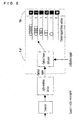
- the received signal image generation section 1 shown in Figure 3 comprises a serial/parallel conversion section 1a and a display section 1b.
- the serial/parallel conversion section 1a can comprise, for example, a fiber coupler and optical fibers along which optical signals are branched by the fiber coupler.
- the display section 1b By means of the display section 1b, light from the optical fibers of the serial/parallel conversion section 1a is projected onto the lens 2 as substantially parallel beams.
- N optical fibers are connected to the fiber coupler, where N is the number of signal bits of serial signals input to the fiber coupler.
- T is the pulse width of one bit of a received signal
- the length of each fiber is adjusted to produce a propagation delay time differences of (N-1)T, (N-2)T, ..., 2T, T, 0 across the first to the last input bits, whereby the serial signals output from the optical fibers are delivered to the display section 1b with the bit strings thereof parallelized.
- the display section 1b only outputs a received signal image for the duration of the output from the optical fibers of the last signal bit having a zero delay difference, so signals output from the photoelectric conversion element 6 at that timing have to be used to identify the transmission information. Therefore, a configuration is used whereby, for example, the photoelectric conversion element 6 signal is received and an optical signal that is also received by the processing means used to extrapolate proper signals is supplied to enable determination of the timing at which the last bit of the optical signal is displayed on the display section 1b.
- the propagation delay time is adjusted by changing the length of the optical fiber transmission path, since attenuation is lower with a shorter path and higher with a long path, in adjusting the intensity of a branched optical signal, it is desirable to take into consideration the amount of attenuation of the fibers corresponding to each bit to ensure that the optical signals supplied to the display section 1b are of substantially equal intensity.
- the display section 1b can be comprised of characters and symbols formed of a translucent material, so that passing the light beams through the translucent material produces a luminescent display of characters and symbols corresponding to the shape of the material.
- the display section 1b is not limited to the above configuration, but may instead have any configuration that enables such display of characters and symbols corresponding to the bit signals.
- the light-emitting devices or light-radiating devices that are activated by optical signals from the serial/parallel conversion section 1a are connected to enable the display section 1b to be configured.
- the display section 1b could be thus configured to emit or radiate light only when the intensity of a signal input from the serial/parallel conversion section 1a is above a specific level.
- Two-dimensional images displayed by a display section 1b thus configured and corresponding to bit values (zeros and ones) parallelized by the serial/parallel conversion section 1a, have portions that are displayed, such as characters and symbols, and portions that are not displayed, which together form a single received signal image.
- the first optical fiber displays K when the value of the first bit is “1” and the relative delay time is 5T
- the second optical fiber displays Z when the value of the second bit is “1” and the relative delay time is 4T
- the third optical fiber displays X when the value of the third bit is “1” and the relative delay time is 3T
- the fourth optical fiber displays G when the value of the fourth bit is "1” and the relative delay time is 2T
- the fifth optical fiber displays R when the value of the fifth bit is "1” and the relative delay time is 1T
- the sixth optical fiber displays W when the value of the sixth bit is "1" with a zero relative delay time.
- the bit value is "0"
- the light-emitting or light-radiating devices do not operate, so nothing is displayed.
- FIG. 3 shows the six-bit received signal 101011.
- the first bit is “1”, with a relative delay time of 5T, so K is displayed; the second bit is “1”, with a relative delay time of 4T, so Z is displayed; the third bit is "0”, with a relative delay time of 3T, so a blank (_) is displayed; the fourth bit is "1", with a relative delay time of 2T, so G is displayed; the fifth bit is "0”, with a relative delay time of T, so a blank is displayed; and the sixth bit is "1", with a relative delay time of T, so W is displayed.
- W_G_ZK is displayed.
- Figure 4 shows an example of an actual image as seen from the output side of the received signal image generation section 1. In the case of this drawing, looking at the page, the first bit is on the right and the sixth bit on the left.
- a different alphabetic character (graphical form) is assigned to correspond to each bit position with the aim of increasing the pattern-matching accuracy. While the use of alphabetic characters is not limitative, the graphical forms used should be ones that appear with a marked difference in terms of magnitude of correlation value. In accordance with the basic principle of matching, even in the case of a parallelized signal image formed by the presence or absence of light spots having a simple shape such as round or square, correlation can be judged from an array of such light spots, so the method is not limited to a technique of creating a received image signal by assigning different graphical forms to the bit positions or values. Similarly, the shape of the bit arrays is not limited to the single horizontal line shown in this example. In the case of a long data length, it can be arrayed in two or three or more rows, or radially, or in a circle, square or any other shape desired.
- the received signal image generation section is not limited to the one shown in the above example, but may be of any configuration that is able to generate an image corresponding to a received signal.
- the received signal image generation section is not limited to the one shown in the above example, but may be of any configuration that is able to generate an image corresponding to a received signal.
- the received signal image generation section is not limited to the one shown in the above example, but may be of any configuration that is able to generate an image corresponding to a received signal.
- the received signal image generation section is not limited to the one shown in the above example, but may be of any configuration that is able to generate an image corresponding to a received signal.
- the received signal image generation section is not limited to the one shown in the above example, but may be of any configuration that is able to generate an image corresponding to a received signal.
- the received signal image generation section is not limited to the one shown in the above example, but may be of any configuration that is able to generate an image corresponding to a received signal.
- serial/parallel conversion function that the received signal image generation section 1 is provided with is not limited to the one of the above example.
- the configuration of Figure 5 can be used, in which, in place of a fiber coupler, a serial/parallel conversion section 1a' uses an optical beam deflector that deflects a received optical signal to different output paths.
- each first signal bit is deflected to a first optical fiber, the second bit to the second fiber, the third bit to the third fiber, the fourth bit to the fourth fiber, the fifth bit to the fifth fiber and the sixth bit to the sixth fiber, thereby converting a serial signal to a parallel signal.
- the signal does not have to be branched to each fiber, so the light output from the fiber end has substantially the same intensity as the input signal. So the advantage of using a beam deflector is that it makes it readily possible to obtain the amount of light required to generate a received signal image without using an amplifier.
- the signals received by the received signal image generation section 1 for generating received image signals are not limited to optical signals, and may be electric or radio wave signals transmitted by wire or wirelessly.
- a configuration such as the one shown in Figure 6 can be used when the received signal is a digital signal transmitted as an electric or radio wave.
- the signal can be converted to a parallel using the same kind of processing as that of the serial/parallel conversion sections 1a and 1a'.
- the configuration for converting the optical signal to a parallel signal is not limited to the above one.
- the configuration shown in Figure 7 can be used, in which the received signal is distributed to a first signal line having a first delay circuit with a relative delay time of 5T, a second signal line having a second delay circuit with a relative delay time of 4T, a third signal line having a third delay circuit with a relative delay time of 3T, a fourth signal line having a fourth delay circuit with a relative delay time of 2T, a fifth signal line having a fifth delay circuit with a relative delay time of T and a sixth signal line having no delay circuit, thereby activating a first light-emitting device (for K), a second light-emitting device (for Z), a third light-emitting device (for X), a fourth light-emitting device (for G), a fifth light-emitting device (for R) and a sixth light-e
- the first to fifth bits are used for the on/off switching of the respective first to fifth light-emitting devices, to thereby generate the received signal image.
- the matched filter 3 on which is projected the Fourier-transformed image of the received signal image thus generated comprises a film of a translucent material onto which is formed a conjugate image of the received signal pattern image that has been Fourier-transformed.
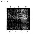
- Figure 8 shows an example of an original received signal pattern image used for this, which is positioned in regions into which the received signal pattern images shown in the decoding table of Figure 1 are divided on a transmitted information by information basis (hereinafter, these will be referred to as "received signal pattern regions").
- the signal images (alphabetic character images corresponding to the bit strings) corresponding to the received signal patterns are arranged in the regions a to g corresponding to the transmitted information.
- Figure 8 shows an enlarged view of part of the matched filter 3.
- the output image from the matched filter 3 is a superposed image that is a conjugate of the Fourier-transformed received signal image and the Fourier-transformed received signal pattern image.
- the output image from the matched filter 3 includes the outcome of the calculated correlation between received signal image and received signal pattern image.
- the correlation projection image that is the output image Fourier-transformed by the lens 4, the point of highest correlation appears as a point of maximum brightness.
- the output image from the lens 4 displayed on the screen 5 includes numerous point images corresponding to correlations with received signal pattern images.
- the brightness of these point images is proportional to the correspondence values between the received signal image and each of the received signal pattern images. That is, the point image indicates the location of maximum correlation with the received signal image. Based on the correspondence between the screen region where the point image of maximum brightness appears and the regions in the received signal pattern image, the proper signal can be interred.
- the maximum correlation value will be obtained in region d of the signal image (the lower left in Figure 8), so in the screen 5 shown in Figure 10, the point image of maximum brightness also appears in the d region at the lower left.
- the photoelectric conversion element 6 converts the point image of maximum brightness thus displayed on the screen 5 to information for region determination processing. For example, if the received signal is 101011, the photoelectric conversion element 6 provides the information that the point image of maximum brightness is located at the lower left, so that if the boundary information of the regions a to g is known, it can be determined that the point image of maximum brightness belongs to region d. That is, based on the correspondence between the region on the screen 5 in which the point of maximum brightness is located and each of the regions of the received signal pattern image, it can be inferred that the proper signal is 100011 (W._ZK), enabling identification of the transmission information, 100, of the proper signal. In this way, high-speed digital signal decoding is achieved by optical information processing.
- the screen 5 is used to make the point of maximum brightness visible.
- this is not limitative. Instead, a configuration can be used in which the Fourier-transformed image is projected directly to the photoelectric conversion element 6.
- the method of identifying the transmission information from the information from the photoelectric conversion element 6 any of the various conventional methods can be used.
- the optical output from the received signal image generation section 1. when the light projected at the matched filter 3 is coherent light, detection accuracy is improved since the brightness of the image that coincides with the pattern is higher. The following explanation is given with reference to an example in which a coherent image is projected at the first lens.
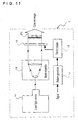
- Figure 11 shows a second example of the received signal image generation section used in the digital signal decoding apparatus of Figure 2.
- the received signal image generation section 1' is used to obtain a coherent image by projecting liquid-crystal backlight as the coherent light.
- the received signal is input to the pattern generator 11, which generates a fixed pattern (graphical form) for each signal bit.
- the pattern signals thus generated are applied to a driver section 12 that drives an electric-signal addressable liquid-crystal panel 13 to display an image corresponding to the input signal. If the input signal is 101011, for example, the image "W_G_ZK" would be displayed.
- the laser beam output by laser light source 14 is expanded by means of a beam expander 15 so that the beam is projected onto the whole display region of the liquid-crystal panel 13. Since the beam is projected onto the back of the liquid-crystal panel 13, coherent light is only transmitted by the "W_G_ZK" in the panel transmission state, thereby providing the transmitted coherent image "W_G_ZK” indicated in Figure 11 by the arrow FC.
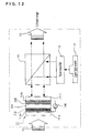
- an image coherency apparatus 7 is located between the received signal image generation section 1 and the first lens 2 to convert the image from the section 1 to a coherent image.
- the function of the image coherency apparatus 7 can be included in the received signal image generation section 1, enabling the section 1 to generate a coherent image. It is shown as a separate function here in order to concentrate on the description of the function of converting the received signal image to a coherent image.
- the received signal image from the received signal image generation section 1 is projected onto an optically addressable spatial optical modulator 71 of the image coherency apparatus 7.
- the optical modulator 71 is constituted by transparent electrodes 712a and 712b formed on the opposing surfaces of a pair of glass plates 711a and 711b, and a photoconductive layer 713, a dielectric mirror 714 and an optical modulation layer 715 disposed between the electrodes 712a and 712b.
- a drive power source 716 is connected across the electrodes 712a and 712b.
- the photoconductive layer 713 is invested with conductivity corresponding to the intensity distribution of the incident light and, via the electrodes 712a and 712b, the drive power source 716 applies a voltage to the optical modulation layer 715 corresponding to the conductive portions.
- an optically modulated region is formed that has the same form as the received signal image from the section 1.
- the beam expander 73 projects the coherent light onto a beam-splitter 74
- the coherent light from beam-splitter 74 that is projected onto the glass plate 711b of the spatial optical modulator 71 is modulated by the optical modulation region produced in the optical modulation layer 715. That is, the laser beam projected onto the glass plate 711b side is optically modulated according to the intensity distribution of the light projected onto the glass plate 711a side, so a coherent image (indicated by the arrow FC in Figure 12) can be obtained from the beam-splitter 74 that corresponds to the received signal image.
- Figure 13 shows how the optical signal is converted to a coherent signal in order to obtain a coherent image.
- a modulator 82 controlled by an optical signal detected by means of an optical detector 81 to modulate the coherent beam from a laser light source 83 it is possible to generate a coherent signal corresponding to the optical signal. Modulation can also be controlled without using an optical detector 81, by inputting the optical signal to a direct-drive type modulator.
- a coherent signal corresponding to the optical signal can also be generated using a laser light source 85 to directly control the modulation of the optical signal detected by the optical detector 84.
- Received signal image generation section 91 uses an incoherent light source to generate a received signal image that is projected onto the entire surface of a correlation filter 92.
- the correlation filter 92 is constituted as a film of translucent material onto which the received signal pattern images have been transferred (images produced by generating a two-dimensional image of each bit string of all transmitted types of proper signal and error patterns derived from each proper signal and disposing a received signal pattern region comprised of an arbitrary proper signal and a group of two-dimensional images of error patterns thereof in a state that enables identification of each proper signal).
- the transmission by the correlation filter 92 enables received signal image and received signal pattern image to be superposed.
- the superposed image passes through a focal length adjusting lens 93 to a translucent screen 94, to thereby obtain a correlation projection image.
- the principle of using incoherent light to process optical signals is described in, for example, pages 106-107 of "Optical Signal Processing Principles," edited by Junpei Tsujiuchi and Kazumi Murata, published by Asakura Co.
- a photoelectric conversion element 95 on the output side of the screen 94 is used to obtain an electric signal corresponding to the optical intensity of the images transmitted by the screen 94.
- Digital signal decoding is thereby effected using decoding processing means (not shown) constituted similarly to that of the first embodiment.
- the correlation filter 92, lens 93 and screen 94 of this embodiment constitute the spatial frequency filtering means that uses optical signal processing to calculate a correlation between a received signal image from the received signal image generation means and a received signal pattern image generated by generating a two-dimensional image of each bit string of all transmitted types of proper signal and error patterns derived from each proper signal and disposing a received signal pattern region comprised of an arbitrary proper signal and a group of two-dimensional images of error patterns thereof in a state that enables identification of each proper signal, to obtain a correlation projection image in which the intensity distribution is proportional to cross-correlation of received signal image and received signal pattern image.
- the lens 93 can be omitted and the distance between the correlation filter 92 and the screen 94, or the size of the screen 94, adjusted to achieve image formation on the screen 94.
- optical signal processing is used to calculate the correlation between received signal images and received signal pattern images to obtain a correlation projection image in which the intensity distribution is proportional to cross-correlation between the received signal images and received signal pattern images.
- transmitted information from the proper signal is identified by extrapolating transmitted proper signals based on the correspondence between a region that includes a point of maximum brightness appearing in the correlation projection image and each received signal pattern region in the received signal pattern images.
- the above digital signal decoding method is realized by a digital signal decoding apparatus comprising received signal image generation means, spatial frequency filtering means and decoding processing means, making the apparatus an effective one for receiving large quantities of information at high speed without errors.
Landscapes
- Engineering & Computer Science (AREA)
- Signal Processing (AREA)
- Optical Communication System (AREA)
- Error Detection And Correction (AREA)
- Detection And Prevention Of Errors In Transmission (AREA)
- Compression Or Coding Systems Of Tv Signals (AREA)
- Image Analysis (AREA)
Applications Claiming Priority (2)
| Application Number | Priority Date | Filing Date | Title |
|---|---|---|---|
| JP2002300066 | 2002-10-15 | ||
| JP2002300066A JP3743799B2 (ja) | 2002-10-15 | 2002-10-15 | ディジタル信号復号方法およびディジタル信号復号装置 |
Publications (3)
| Publication Number | Publication Date |
|---|---|
| EP1411641A2 true EP1411641A2 (de) | 2004-04-21 |
| EP1411641A3 EP1411641A3 (de) | 2004-11-17 |
| EP1411641B1 EP1411641B1 (de) | 2006-06-21 |
Family
ID=32040780
Family Applications (1)
| Application Number | Title | Priority Date | Filing Date |
|---|---|---|---|
| EP03256490A Expired - Lifetime EP1411641B1 (de) | 2002-10-15 | 2003-10-15 | Fehlerkorrigierende Decodierung mittels optischer Signalverarbeitung |
Country Status (5)
| Country | Link |
|---|---|
| US (1) | US7423793B2 (de) |
| EP (1) | EP1411641B1 (de) |
| JP (1) | JP3743799B2 (de) |
| AT (1) | ATE331342T1 (de) |
| DE (1) | DE60306294T2 (de) |
Families Citing this family (4)
| Publication number | Priority date | Publication date | Assignee | Title |
|---|---|---|---|---|
| US7741970B2 (en) | 2006-12-31 | 2010-06-22 | At&T Intellectual Property Ii, L.P. | Method and apparatus for a radio frequency identification repeater |
| US7821524B2 (en) * | 2007-06-26 | 2010-10-26 | Microsoft Corporation | Adaptive contextual filtering |
| US9042281B2 (en) * | 2010-12-08 | 2015-05-26 | At&T Intellectual Property I, L.P. | Method and apparatus for initializing an RFID tag via an optical display |
| JP6466684B2 (ja) * | 2014-10-17 | 2019-02-06 | 三星電子株式会社Samsung Electronics Co.,Ltd. | 可視光送信装置、可視光受信装置、可視光通信システム、可視光通信方法及びプログラム |
Family Cites Families (14)
| Publication number | Priority date | Publication date | Assignee | Title |
|---|---|---|---|---|
| US3125683A (en) * | 1959-05-04 | 1964-03-17 | I mage | |
| US5129058A (en) * | 1988-07-06 | 1992-07-07 | Ricoh Company, Ltd. | Parallel optical image processing system |
| US4995090A (en) * | 1989-02-07 | 1991-02-19 | The University Of Michigan | Optoelectronic pattern comparison system |
| JPH06332021A (ja) * | 1993-05-21 | 1994-12-02 | Fuji Photo Film Co Ltd | 光情報処理システム |
| US5668647A (en) * | 1994-01-04 | 1997-09-16 | Lucent Technologies Inc. | Method and apparatus and for processing ultrafast optical signals |
| JPH08129149A (ja) | 1994-11-01 | 1996-05-21 | Matsushita Electric Ind Co Ltd | 光学的情報処理装置 |
| US5838650A (en) * | 1996-06-26 | 1998-11-17 | Lucent Technologies Inc. | Image quality compensation method and apparatus for holographic data storage system |
| US6275311B1 (en) * | 1997-06-30 | 2001-08-14 | Pirelli Cavi E Sistemi S.P.A. | Optical device for processing an optical digital signal |
| US6160656A (en) * | 1998-01-07 | 2000-12-12 | Templex Technology, Inc. | Method and apparatus for optical correlation recognition by time-integrated nonlinear detection |
| GB2334641A (en) * | 1998-02-11 | 1999-08-25 | Northern Telecom Ltd | Multiplexed transmission of optical signals |
| JP4037979B2 (ja) | 1999-01-25 | 2008-01-23 | 日本テキサス・インスツルメンツ株式会社 | データ復調方式、データ復調方法及びデータ復調回路 |
| US6216267B1 (en) * | 1999-07-26 | 2001-04-10 | Rockwell Collins, Inc. | Media capture and compression communication system using holographic optical classification, voice recognition and neural network decision processing |
| JP2001251244A (ja) | 2000-03-02 | 2001-09-14 | Nippon Telegr & Teleph Corp <Ntt> | 伝送装置及び光伝送システム |
| US7130292B2 (en) * | 2000-06-02 | 2006-10-31 | Essex Corporation | Optical processor enhanced receiver architecture (opera) |
-
2002
- 2002-10-15 JP JP2002300066A patent/JP3743799B2/ja not_active Expired - Lifetime
-
2003
- 2003-10-15 AT AT03256490T patent/ATE331342T1/de not_active IP Right Cessation
- 2003-10-15 EP EP03256490A patent/EP1411641B1/de not_active Expired - Lifetime
- 2003-10-15 US US10/684,548 patent/US7423793B2/en not_active Expired - Fee Related
- 2003-10-15 DE DE60306294T patent/DE60306294T2/de not_active Expired - Lifetime
Also Published As
| Publication number | Publication date |
|---|---|
| EP1411641A3 (de) | 2004-11-17 |
| US20040175184A1 (en) | 2004-09-09 |
| JP2004133345A (ja) | 2004-04-30 |
| ATE331342T1 (de) | 2006-07-15 |
| EP1411641B1 (de) | 2006-06-21 |
| JP3743799B2 (ja) | 2006-02-08 |
| DE60306294D1 (de) | 2006-08-03 |
| US7423793B2 (en) | 2008-09-09 |
| DE60306294T2 (de) | 2007-04-26 |
Similar Documents
| Publication | Publication Date | Title |
|---|---|---|
| US7755820B2 (en) | Two-dimensional modulation method for hologram recording and hologram apparatus with encoder for driving SLM displaying boundary portion | |
| US6661725B2 (en) | Apparatus for storing/restoring holographic data and method for coding/decoding holographic data | |
| US20100196004A1 (en) | Topologically multiplexed optical data communication | |
| CN101080727A (zh) | 光学相关设备和方法 | |
| US7715072B2 (en) | Hologram retrieval method and holographic recording and reproducing apparatus | |
| US7423793B2 (en) | Method and apparatus for decoding digital signal | |
| EP2083420A1 (de) | Hologrammaufzeichnungseinrichtung, hologrammwiedergabeeinrichtung, informationskodierungsverfahren, aufzeichnungsverfahren und informationswiedergabeverfahren | |
| US7826114B2 (en) | Hologram recording apparatus, hologram recording method and optical recording medium | |
| KR100355998B1 (ko) | 홀로그래픽 디지털 저장 및 재생 시스템과 데이터코딩/디코딩 방법 | |
| AU665873B2 (en) | Information recording method and apparatus | |
| US7800801B2 (en) | Two-dimensional coding method | |
| JP2007156801A (ja) | 光情報記録方法及び再生方法 | |
| US4703361A (en) | Picture multiplex analysis hybrid device | |
| CN101536094A (zh) | 全息图记录装置、全息图再现装置、信息编码方法、记录方法及信息再现方法 | |
| JP4407279B2 (ja) | 空間光変調器及び空間光変調方法 | |
| KR20090028936A (ko) | 데이터의 인코딩/디코딩 방법, 데이터의 검출방법 및데이터의 기록/재생 방법 | |
| US20100008201A1 (en) | Demodulation method and apparatus | |
| JP2008033260A (ja) | ホログラム記録装置、ホログラム再生装置、ホログラム記録方法およびホログラム再生方法 | |
| KR100551372B1 (ko) | 홀로그래픽 디지털 데이터 시스템의 코딩 및 디코딩 방법 | |
| KR100822633B1 (ko) | 광정보의 모듈레이션 방법 및 그 장치 | |
| JP2000122013A (ja) | 位相変調したnビットの入力直列シ―ケンスを処理する光学装置及び位相変調したnビットの光直列シ―ケンスを所定のnビットのシ―ケンスと光学的に比較する方法 | |
| KR100555968B1 (ko) | 홀로그래픽 디지털 데이터 저장 시스템의 코딩 장치 및 방법 | |
| KR100551369B1 (ko) | 홀로그래픽 디지털 데이터 저장 시스템의 코딩 장치 및 방법 | |
| US20030179984A1 (en) | Method and device for direct ultrahigh speed conversion from time signal to space signal | |
| KR100589620B1 (ko) | 홀로그래픽 데이터 엔코딩/디코딩 방법 |
Legal Events
| Date | Code | Title | Description |
|---|---|---|---|
| PUAI | Public reference made under article 153(3) epc to a published international application that has entered the european phase |
Free format text: ORIGINAL CODE: 0009012 |
|
| AK | Designated contracting states |
Kind code of ref document: A2 Designated state(s): AT BE BG CH CY CZ DE DK EE ES FI FR GB GR HU IE IT LI LU MC NL PT RO SE SI SK TR |
|
| AX | Request for extension of the european patent |
Extension state: AL LT LV MK |
|
| RAP1 | Party data changed (applicant data changed or rights of an application transferred) |
Owner name: NATIONAL INSTITUTE OF INFORMATION AND COMMUNICATIO |
|
| PUAL | Search report despatched |
Free format text: ORIGINAL CODE: 0009013 |
|
| AK | Designated contracting states |
Kind code of ref document: A3 Designated state(s): AT BE BG CH CY CZ DE DK EE ES FI FR GB GR HU IE IT LI LU MC NL PT RO SE SI SK TR |
|
| AX | Request for extension of the european patent |
Extension state: AL LT LV MK |
|
| RIC1 | Information provided on ipc code assigned before grant |
Ipc: 7G 06K 9/74 B Ipc: 7H 03M 13/05 A |
|
| 17P | Request for examination filed |
Effective date: 20050512 |
|
| 17Q | First examination report despatched |
Effective date: 20050613 |
|
| AKX | Designation fees paid |
Designated state(s): AT BE BG CH CY CZ DE DK EE ES FI FR GB GR HU IE IT LI LU MC NL PT RO SE SI SK TR |
|
| GRAP | Despatch of communication of intention to grant a patent |
Free format text: ORIGINAL CODE: EPIDOSNIGR1 |
|
| RAP1 | Party data changed (applicant data changed or rights of an application transferred) |
Owner name: NATIONAL INSTITUTE OF INFORMATION ANDCOMMUNICATION |
|
| RAP1 | Party data changed (applicant data changed or rights of an application transferred) |
Owner name: NATIONAL INSTITUTE OF INFORMATION AND C |
|
| GRAS | Grant fee paid |
Free format text: ORIGINAL CODE: EPIDOSNIGR3 |
|
| GRAA | (expected) grant |
Free format text: ORIGINAL CODE: 0009210 |
|
| AK | Designated contracting states |
Kind code of ref document: B1 Designated state(s): AT BE BG CH CY CZ DE DK EE ES FI FR GB GR HU IE IT LI LU MC NL PT RO SE SI SK TR |
|
| PG25 | Lapsed in a contracting state [announced via postgrant information from national office to epo] |
Ref country code: IT Free format text: LAPSE BECAUSE OF FAILURE TO SUBMIT A TRANSLATION OF THE DESCRIPTION OR TO PAY THE FEE WITHIN THE PRESCRIBED TIME-LIMIT;WARNING: LAPSES OF ITALIAN PATENTS WITH EFFECTIVE DATE BEFORE 2007 MAY HAVE OCCURRED AT ANY TIME BEFORE 2007. THE CORRECT EFFECTIVE DATE MAY BE DIFFERENT FROM THE ONE RECORDED. Effective date: 20060621 Ref country code: CZ Free format text: LAPSE BECAUSE OF FAILURE TO SUBMIT A TRANSLATION OF THE DESCRIPTION OR TO PAY THE FEE WITHIN THE PRESCRIBED TIME-LIMIT Effective date: 20060621 Ref country code: AT Free format text: LAPSE BECAUSE OF FAILURE TO SUBMIT A TRANSLATION OF THE DESCRIPTION OR TO PAY THE FEE WITHIN THE PRESCRIBED TIME-LIMIT Effective date: 20060621 Ref country code: SK Free format text: LAPSE BECAUSE OF FAILURE TO SUBMIT A TRANSLATION OF THE DESCRIPTION OR TO PAY THE FEE WITHIN THE PRESCRIBED TIME-LIMIT Effective date: 20060621 Ref country code: LI Free format text: LAPSE BECAUSE OF FAILURE TO SUBMIT A TRANSLATION OF THE DESCRIPTION OR TO PAY THE FEE WITHIN THE PRESCRIBED TIME-LIMIT Effective date: 20060621 Ref country code: SI Free format text: LAPSE BECAUSE OF FAILURE TO SUBMIT A TRANSLATION OF THE DESCRIPTION OR TO PAY THE FEE WITHIN THE PRESCRIBED TIME-LIMIT Effective date: 20060621 Ref country code: BE Free format text: LAPSE BECAUSE OF FAILURE TO SUBMIT A TRANSLATION OF THE DESCRIPTION OR TO PAY THE FEE WITHIN THE PRESCRIBED TIME-LIMIT Effective date: 20060621 Ref country code: FI Free format text: LAPSE BECAUSE OF FAILURE TO SUBMIT A TRANSLATION OF THE DESCRIPTION OR TO PAY THE FEE WITHIN THE PRESCRIBED TIME-LIMIT Effective date: 20060621 Ref country code: RO Free format text: LAPSE BECAUSE OF FAILURE TO SUBMIT A TRANSLATION OF THE DESCRIPTION OR TO PAY THE FEE WITHIN THE PRESCRIBED TIME-LIMIT Effective date: 20060621 Ref country code: CH Free format text: LAPSE BECAUSE OF FAILURE TO SUBMIT A TRANSLATION OF THE DESCRIPTION OR TO PAY THE FEE WITHIN THE PRESCRIBED TIME-LIMIT Effective date: 20060621 |
|
| REG | Reference to a national code |
Ref country code: GB Ref legal event code: FG4D |
|
| REG | Reference to a national code |
Ref country code: CH Ref legal event code: EP |
|
| REG | Reference to a national code |
Ref country code: IE Ref legal event code: FG4D |
|
| REF | Corresponds to: |
Ref document number: 60306294 Country of ref document: DE Date of ref document: 20060803 Kind code of ref document: P |
|
| PG25 | Lapsed in a contracting state [announced via postgrant information from national office to epo] |
Ref country code: DK Free format text: LAPSE BECAUSE OF FAILURE TO SUBMIT A TRANSLATION OF THE DESCRIPTION OR TO PAY THE FEE WITHIN THE PRESCRIBED TIME-LIMIT Effective date: 20060921 Ref country code: SE Free format text: LAPSE BECAUSE OF FAILURE TO SUBMIT A TRANSLATION OF THE DESCRIPTION OR TO PAY THE FEE WITHIN THE PRESCRIBED TIME-LIMIT Effective date: 20060921 |
|
| PG25 | Lapsed in a contracting state [announced via postgrant information from national office to epo] |
Ref country code: ES Free format text: LAPSE BECAUSE OF FAILURE TO SUBMIT A TRANSLATION OF THE DESCRIPTION OR TO PAY THE FEE WITHIN THE PRESCRIBED TIME-LIMIT Effective date: 20061002 |
|
| PG25 | Lapsed in a contracting state [announced via postgrant information from national office to epo] |
Ref country code: IE Free format text: LAPSE BECAUSE OF NON-PAYMENT OF DUE FEES Effective date: 20061016 |
|
| PG25 | Lapsed in a contracting state [announced via postgrant information from national office to epo] |
Ref country code: MC Free format text: LAPSE BECAUSE OF NON-PAYMENT OF DUE FEES Effective date: 20061031 |
|
| PG25 | Lapsed in a contracting state [announced via postgrant information from national office to epo] |
Ref country code: PT Free format text: LAPSE BECAUSE OF FAILURE TO SUBMIT A TRANSLATION OF THE DESCRIPTION OR TO PAY THE FEE WITHIN THE PRESCRIBED TIME-LIMIT Effective date: 20061121 |
|
| REG | Reference to a national code |
Ref country code: CH Ref legal event code: PL |
|
| ET | Fr: translation filed | ||
| PLBE | No opposition filed within time limit |
Free format text: ORIGINAL CODE: 0009261 |
|
| STAA | Information on the status of an ep patent application or granted ep patent |
Free format text: STATUS: NO OPPOSITION FILED WITHIN TIME LIMIT |
|
| 26N | No opposition filed |
Effective date: 20070322 |
|
| PG25 | Lapsed in a contracting state [announced via postgrant information from national office to epo] |
Ref country code: GR Free format text: LAPSE BECAUSE OF FAILURE TO SUBMIT A TRANSLATION OF THE DESCRIPTION OR TO PAY THE FEE WITHIN THE PRESCRIBED TIME-LIMIT Effective date: 20060922 |
|
| PG25 | Lapsed in a contracting state [announced via postgrant information from national office to epo] |
Ref country code: BG Free format text: LAPSE BECAUSE OF FAILURE TO SUBMIT A TRANSLATION OF THE DESCRIPTION OR TO PAY THE FEE WITHIN THE PRESCRIBED TIME-LIMIT Effective date: 20060921 Ref country code: EE Free format text: LAPSE BECAUSE OF FAILURE TO SUBMIT A TRANSLATION OF THE DESCRIPTION OR TO PAY THE FEE WITHIN THE PRESCRIBED TIME-LIMIT Effective date: 20060621 |
|
| PG25 | Lapsed in a contracting state [announced via postgrant information from national office to epo] |
Ref country code: LU Free format text: LAPSE BECAUSE OF NON-PAYMENT OF DUE FEES Effective date: 20061015 Ref country code: TR Free format text: LAPSE BECAUSE OF FAILURE TO SUBMIT A TRANSLATION OF THE DESCRIPTION OR TO PAY THE FEE WITHIN THE PRESCRIBED TIME-LIMIT Effective date: 20060621 Ref country code: HU Free format text: LAPSE BECAUSE OF FAILURE TO SUBMIT A TRANSLATION OF THE DESCRIPTION OR TO PAY THE FEE WITHIN THE PRESCRIBED TIME-LIMIT Effective date: 20061222 |
|
| PG25 | Lapsed in a contracting state [announced via postgrant information from national office to epo] |
Ref country code: CY Free format text: LAPSE BECAUSE OF FAILURE TO SUBMIT A TRANSLATION OF THE DESCRIPTION OR TO PAY THE FEE WITHIN THE PRESCRIBED TIME-LIMIT Effective date: 20060621 |
|
| PGFP | Annual fee paid to national office [announced via postgrant information from national office to epo] |
Ref country code: DE Payment date: 20091130 Year of fee payment: 7 |
|
| PGFP | Annual fee paid to national office [announced via postgrant information from national office to epo] |
Ref country code: NL Payment date: 20090821 Year of fee payment: 7 |
|
| PGFP | Annual fee paid to national office [announced via postgrant information from national office to epo] |
Ref country code: GB Payment date: 20091026 Year of fee payment: 7 |
|
| REG | Reference to a national code |
Ref country code: NL Ref legal event code: V1 Effective date: 20110501 |
|
| GBPC | Gb: european patent ceased through non-payment of renewal fee |
Effective date: 20101015 |
|
| PG25 | Lapsed in a contracting state [announced via postgrant information from national office to epo] |
Ref country code: FR Free format text: LAPSE BECAUSE OF NON-PAYMENT OF DUE FEES Effective date: 20101102 |
|
| REG | Reference to a national code |
Ref country code: FR Ref legal event code: ST Effective date: 20110630 |
|
| PG25 | Lapsed in a contracting state [announced via postgrant information from national office to epo] |
Ref country code: GB Free format text: LAPSE BECAUSE OF NON-PAYMENT OF DUE FEES Effective date: 20101015 Ref country code: NL Free format text: LAPSE BECAUSE OF NON-PAYMENT OF DUE FEES Effective date: 20110501 |
|
| REG | Reference to a national code |
Ref country code: DE Ref legal event code: R119 Ref document number: 60306294 Country of ref document: DE Effective date: 20110502 |
|
| PGFP | Annual fee paid to national office [announced via postgrant information from national office to epo] |
Ref country code: FR Payment date: 20090916 Year of fee payment: 7 |
|
| PG25 | Lapsed in a contracting state [announced via postgrant information from national office to epo] |
Ref country code: DE Free format text: LAPSE BECAUSE OF NON-PAYMENT OF DUE FEES Effective date: 20110502 |