EP1409298B2 - Device and method for triggering a passenger protection means in a motor vehicle - Google Patents
Device and method for triggering a passenger protection means in a motor vehicle Download PDFInfo
- Publication number
- EP1409298B2 EP1409298B2 EP02754441A EP02754441A EP1409298B2 EP 1409298 B2 EP1409298 B2 EP 1409298B2 EP 02754441 A EP02754441 A EP 02754441A EP 02754441 A EP02754441 A EP 02754441A EP 1409298 B2 EP1409298 B2 EP 1409298B2
- Authority
- EP
- European Patent Office
- Prior art keywords
- unit
- threshold value
- signal
- sensor unit
- sensor
- Prior art date
- Legal status (The legal status is an assumption and is not a legal conclusion. Google has not performed a legal analysis and makes no representation as to the accuracy of the status listed.)
- Expired - Lifetime
Links
Images

Classifications
-
- B—PERFORMING OPERATIONS; TRANSPORTING
- B60—VEHICLES IN GENERAL
- B60R—VEHICLES, VEHICLE FITTINGS, OR VEHICLE PARTS, NOT OTHERWISE PROVIDED FOR
- B60R21/00—Arrangements or fittings on vehicles for protecting or preventing injuries to occupants or pedestrians in case of accidents or other traffic risks
- B60R21/01—Electrical circuits for triggering passive safety arrangements, e.g. airbags, safety belt tighteners, in case of vehicle accidents or impending vehicle accidents
- B60R21/013—Electrical circuits for triggering passive safety arrangements, e.g. airbags, safety belt tighteners, in case of vehicle accidents or impending vehicle accidents including means for detecting collisions, impending collisions or roll-over
- B60R21/0132—Electrical circuits for triggering passive safety arrangements, e.g. airbags, safety belt tighteners, in case of vehicle accidents or impending vehicle accidents including means for detecting collisions, impending collisions or roll-over responsive to vehicle motion parameters, e.g. to vehicle longitudinal or transversal deceleration or speed value
-
- B—PERFORMING OPERATIONS; TRANSPORTING
- B60—VEHICLES IN GENERAL
- B60R—VEHICLES, VEHICLE FITTINGS, OR VEHICLE PARTS, NOT OTHERWISE PROVIDED FOR
- B60R21/00—Arrangements or fittings on vehicles for protecting or preventing injuries to occupants or pedestrians in case of accidents or other traffic risks
- B60R21/01—Electrical circuits for triggering passive safety arrangements, e.g. airbags, safety belt tighteners, in case of vehicle accidents or impending vehicle accidents
- B60R21/013—Electrical circuits for triggering passive safety arrangements, e.g. airbags, safety belt tighteners, in case of vehicle accidents or impending vehicle accidents including means for detecting collisions, impending collisions or roll-over
- B60R21/0136—Electrical circuits for triggering passive safety arrangements, e.g. airbags, safety belt tighteners, in case of vehicle accidents or impending vehicle accidents including means for detecting collisions, impending collisions or roll-over responsive to actual contact with an obstacle, e.g. to vehicle deformation, bumper displacement or bumper velocity relative to the vehicle
-
- B—PERFORMING OPERATIONS; TRANSPORTING
- B60—VEHICLES IN GENERAL
- B60R—VEHICLES, VEHICLE FITTINGS, OR VEHICLE PARTS, NOT OTHERWISE PROVIDED FOR
- B60R21/00—Arrangements or fittings on vehicles for protecting or preventing injuries to occupants or pedestrians in case of accidents or other traffic risks
- B60R21/01—Electrical circuits for triggering passive safety arrangements, e.g. airbags, safety belt tighteners, in case of vehicle accidents or impending vehicle accidents
- B60R21/013—Electrical circuits for triggering passive safety arrangements, e.g. airbags, safety belt tighteners, in case of vehicle accidents or impending vehicle accidents including means for detecting collisions, impending collisions or roll-over
- B60R21/0132—Electrical circuits for triggering passive safety arrangements, e.g. airbags, safety belt tighteners, in case of vehicle accidents or impending vehicle accidents including means for detecting collisions, impending collisions or roll-over responsive to vehicle motion parameters, e.g. to vehicle longitudinal or transversal deceleration or speed value
- B60R2021/01322—Electrical circuits for triggering passive safety arrangements, e.g. airbags, safety belt tighteners, in case of vehicle accidents or impending vehicle accidents including means for detecting collisions, impending collisions or roll-over responsive to vehicle motion parameters, e.g. to vehicle longitudinal or transversal deceleration or speed value comprising variable thresholds, e.g. depending from other collision parameters
-
- B—PERFORMING OPERATIONS; TRANSPORTING
- B60—VEHICLES IN GENERAL
- B60R—VEHICLES, VEHICLE FITTINGS, OR VEHICLE PARTS, NOT OTHERWISE PROVIDED FOR
- B60R21/00—Arrangements or fittings on vehicles for protecting or preventing injuries to occupants or pedestrians in case of accidents or other traffic risks
- B60R21/01—Electrical circuits for triggering passive safety arrangements, e.g. airbags, safety belt tighteners, in case of vehicle accidents or impending vehicle accidents
- B60R21/013—Electrical circuits for triggering passive safety arrangements, e.g. airbags, safety belt tighteners, in case of vehicle accidents or impending vehicle accidents including means for detecting collisions, impending collisions or roll-over
- B60R21/0132—Electrical circuits for triggering passive safety arrangements, e.g. airbags, safety belt tighteners, in case of vehicle accidents or impending vehicle accidents including means for detecting collisions, impending collisions or roll-over responsive to vehicle motion parameters, e.g. to vehicle longitudinal or transversal deceleration or speed value
- B60R2021/01325—Vertical acceleration
Definitions
- the invention relates to a device and a method for triggering an occupant protection device in a motor vehicle with a central control unit, in which a central sensor unit is arranged, and with at least one raw data transmitting sensor unit.
- the central control unit has a linking unit and a threshold value comparison unit for each raw data transmitting sensor unit, the signal of the central sensor unit being fed to a first signal input of the linking unit and the signal of the raw data transmitting sensor unit to a second signal input of the linking unit.
- the signal output of the linking unit is connected to the Schwellwertinerritt and the signal output of the Schwellwertinerritt is connected to the trip unit of the respective sensor unit occupant protection means, so that the trip unit then triggers the occupant protection means connected to it when the signal output of the link unit is greater than a threshold value of the associated threshold value comparator unit is.
- measurement signals from sensor units must be transmitted to a central processing unit within a motor vehicle.
- the signals are transmitted from decentralized sensor units to the central control unit of the motor vehicle.
- the preferred place for the arrangement of such decentralized sensor units, the so-called satellite units, is exactly at the points of the motor vehicle at which, in the event of a collision accident, the best signal to be evaluated is to be expected.
- acceleration sensor units are mounted on the so-called sill below the vehicle seat of a motor vehicle and in the vicinity of the motor vehicle side door. If pressure sensor units are used as sensor units, so-called pressure satellites, these are arranged in a closed cavity, preferably in the side doors.
- Such a pressure sensor unit is for example from the European Patent EP 0 667 822 B1 known.
- a control unit for an occupant protection system wherein a pressure sensor detects the adiabatic pressure rise in the side door of a vehicle during an impact accident; Based on the measured course of the change in air pressure, an occupant protection device may be activated (local column 2, line 43 to column 3, line 22).
- a suitable triggering decision for an occupant protection means can be made, in which the signal of only one sensor unit does not provide sufficient security for a correct triggering decision.
- a suitable arrangement of an acceleration sensor unit in the B-pillar of a motor vehicle impact events on the rigid vehicle structure of the motor vehicle are preferably detected, whereas a pressure sensor unit in the vehicle door can primarily detect impacts on the vehicle door. If the signals of both sensor units are now supplied to the central control unit, the central control unit can also detect impact events on the rigid vehicle structure with the aid of the triggering decision of the acceleration sensor unit, which would not be detectable or only detectable very late if a pressure sensor unit were used alone.
- raw data transmitting sensor units Recent developments in the field of occupant protection in motor vehicles use so-called raw data transmitting sensor units. In the raw data transmitting sensor unit, no evaluation of the measured sensor data takes place, as has hitherto often been the case. The electronics contained in the raw data transmitting sensor unit only ensures that the measured data can be transmitted in a suitable manner to a central control unit. An evaluation of the sensor signals takes place there.
- Such raw data transmitting sensor unit using a pressure sensor as a sensor is for example in the German Offenlegungsschrift DE 101 29 945 A1 described.
- the measured sensor values are digitized by the electronics of the sensor unit, for example, and transmitted as a seven-bit data word with a transmission frequency of two kilohertz to the central control unit.
- Sensor units which are distributed as such can also be used as raw data-transmitting sensor units, for example pressure sensor units or acceleration sensor units.
- Object of the present invention is to achieve an improved triggering decision in the release of occupant protection means in a motor vehicle with the use of at least one raw data transmitting sensor unit and a centrally evaluating central control unit.
- the device serves for triggering an occupant protection device and comprises a central control unit, to which the data are fed to at least one raw-data-transmitting sensor unit.
- the central control unit has a central sensor unit, which is preferably integrated in the central control unit.
- the arranged in the central control unit central sensor unit is usually formed from an acceleration sensor with suitable electronic circuitry for conditioning of the sensor signal for the further evaluation of the sensor signal in the central control unit.
- the device according to the invention has at least one raw-data-transmitting sensor unit.
- the raw data transmitting sensor unit is in contrast to the central sensor unit spatially remote from the central control unit so mounted in the motor vehicle that it can detect the forces occurring in a collision accident effects as best as possible.
- Suitable raw data transmitting sensor units are, for example, acceleration sensor units, which are attached to locations of the motor vehicle, where a very good mechanical coupling with the rigid vehicle structure of a motor vehicle is ensured.
- Another suitable sensor unit is, for example, a pressure sensor unit, which is arranged, for example, in a vehicle door in order to detect the pressure rise occurring within the vehicle door in the event of a collision accident.
- the raw data transmitting sensor units are also called satellite units, satellites or only sensor units.
- they are also called acceleration sensor units or acceleration satellites or pressure sensor units or pressure satellites.
- the signals of the satellite units are recorded in the central control unit by a suitable receiving unit. According to the invention, however, the signal of a satellite unit is fed to a signal input of a linking unit, which at the same time is also fed to the signal of the central sensor unit on the input side.
- the output of the linking unit is connected to a threshold value comparator unit.
- the output of the threshold value comparator unit in turn is fed directly or indirectly to a tripping unit of an associated occupant protection means.
- the trip unit can also be accommodated in the ECU as the central sensor unit.
- a threshold comparator unit the incoming signal is compared against a plurality of time-varying and possibly signal-dependent threshold values. If the sum signal supplied to the threshold value comparator unit exceeds or falls below at least one of these threshold values, then the trip unit, which is connected to the threshold value comparator unit, transmits a triggering decision. The trip unit is then in turn the trip decision of Schwellwert miserö directly to the occupant protection means, so that, for example, an airbag or a belt tensioner is activated.
- the device according to the invention comprises at least three satellite units, namely a first, a second and a third satellite unit with first, second and third link units correspondingly connected on the input side, the signal outputs of which are in turn connected to first, second and third threshold comparator units.
- the central sensor unit is also connected to each of these linking units, so that a sum signal from the signals of the central sensor unit and the respective satellite unit is generated as the signal output of each linking unit.
- This linked sum signal is forwarded to the respective threshold value comparator unit, in which each summation signal generated in this way is compared with one or more threshold values of the respective threshold value comparison units. If the signal outputs of the combination units are above or below a certain threshold value, then the respective threshold comparator units divide this with their associated trip units for the assigned occupant protection as a triggering decision with.
- At least one satellite unit is an accelerator satellite unit, in another embodiment at least one satellite unit is a pressure satellite.
- a further preferred embodiment of the invention consists in that the first and the second satellite unit are formed by pressure satellites, whereas the third sensor unit is formed by an acceleration satellite.
- the two pressure satellite units are each arranged in the two front side doors, the acceleration sensor unit, however, is mounted centrally under the vehicle rear seat in the rear part of the vehicle to a rigid body part.
- each of the two front pressure sensor units impact events can be detected, in which the front vehicle doors are pressed.
- this can be detected by the rear acceleration unit fixed to the bodywork.
- the usually very rapid pressure change during the deformation of the vehicle doors is detected by the pressure sensor units.
- a signal is generated which responds both to the rapid deformation of the vehicle doors in a very fast manner and to a pure acceleration of the rigid vehicle structure.
- An at least initially purely accelerating impact event is given, for example, when a narrow object, for example a tree, only hits the B pillar of the motor vehicle.
- a narrow object for example a tree
- the vehicle as a whole is accelerated with its body.
- a slight deformation of the side door is only generated when the impact event is strong enough to twist the entire vehicle and thus also deform the side door.
- the vehicle door For example, if the tree meets only the side door, first of all the vehicle door is first deformed in such a way that a very rapid increase in pressure occurs in the cavity formed by the side door. This pressure increase is detected very quickly by a pressure sensor unit mounted in the side door.
- the acceleration sensor unit in the central control unit only detects a sufficiently high signal when the tree detects and accelerates stiff body parts after the deformation of the side door.
- the advantage of a joint evaluation of a linked signal from the signal of the acceleration sensor unit and the signal of a pressure sensor unit in the side doors of the motor vehicle is that a suitably selected threshold value for the associated signal in the associated threshold comparator unit both in an initially purely accelerating crash accident and in a initially initially purely deforming collision accident can be achieved.
- the threshold value comparator unit is directly or indirectly connected to the trigger unit of the assigned occupant protection means, for example a side airbag, the fastest deployment of the occupant protection means most suitable for this type of accident can be brought about by means of a linked signal of a satellite unit with the central sensor unit.
- the signal of the third acceleration sensor unit whose signal is also linked in its associated linking unit with the signal of the central sensor unit, can now be used to similarly cause fast and safe triggering decisions of a side airbag, especially if rigid body parts of the rear vehicle part an impacting object is hit.
- the central sensor unit in the central control unit will also be able to detect a lateral acceleration signal in the event of such an impact accident since the central sensor unit or the central control unit surrounding it is also firmly connected to the vehicle body.
- a combination of the two acceleration signals of the central sensor unit and the rear acceleration satellite therefore leads to an amplified acceleration signal, which therefore leads to a safer, clear and rapid exceeding of the threshold value in the associated threshold comparator unit and therefore also in the case of a rear impact accident.
- the third linking unit of the third sensor unit is connected on the output side simultaneously to the third threshold comparator unit and a fourth threshold comparator unit, wherein the signal output of the third threshold comparator unit is connected to the first trip unit, but the signal output of the fourth threshold comparator unit to the second trip unit.
- the third acceleration sensor unit detect both positive and negative accelerations perpendicular to the direction of travel of the motor vehicle.
- the third threshold comparator unit consequently transmits the exceeding and the fourth threshold comparator unit drops below a threshold value as a triggering criterion for triggering a side airbag for the one vehicle side or the other vehicle side.
- the signal outputs of the third and fourth threshold comparator units which evaluate the sum signal from the signals of the rear acceleration sensor unit and the central sensor unit, are ORed with the signal outputs of the threshold comparator units associated with the same trip unit of an occupant protection means.
- a sum signal of the central sensor unit and the rear acceleration sensor unit or the sum signal of the front pressure sensor unit and the central sensor unit, both of which are associated with, for example, the left side airbag trip unit independently causes a triggering decision of the left side airbag.
- the results of further evaluations of the supplied sensor data of the satellite units and the central sensor unit are used, which are to check the plausibility of the signals.
- the safing unit checks whether the individual signals of the sensor units present to the central control unit alone are already above a comparatively low threshold value.
- the safety unit associated with a left-hand acceleration sensor unit can also check as a plausibility test whether matching but signed data of the right-hand acceleration sensor unit are present simultaneously with the sensor data of the left acceleration sensor unit or vice versa.
- a safing unit can also check whether a plausible signal is also generated in the central sensor unit at the same time as an acceleration sensor unit arranged in the rear of the motor vehicle.
- the safing unit can determine the direction from which an impacting object impinges on a vehicle rear or on the front side of the vehicle.
- Such a difference signal generated in the safing unit can also be used to check the correctness of, for example, the sum signal from the signal of the vehicle-mounted satellite unit and the central sensor unit.
- the difference signal for example in the safing unit, is compared against a suitable threshold value. Subsequently, like the other possible plausibilizing signals of a safing unit already described, it is fed to the signal input of the AND unit, which is connected to the acceleration sensor unit mounted in the rear of the vehicle.
- a suitable method for triggering an occupant protection device in a motor vehicle using the device according to the invention is as follows:
- a linking unit forwards a signal linked from the signal of the central sensor unit and the signal of a raw-data-transmitting sensor unit to a threshold-value comparator unit, in which this linked signal is compared with a threshold value.
- the tripping decision of an occupant protection device is only given by the threshold value comparator unit to an assigned tripping unit if one of the threshold value is undershot or exceeded.
- the signal of each threshold comparator unit is first supplied to an AND gate.
- a further input of the AND gate the output signal of an associated safing unit is supplied, so that the triggering decision of the Schwellwertnerü is only a trip unit of occupant protection means transmitted when both a suitable signal from the threshold comparator unit and the associated safing unit on AND gate on the input side.
- the trigger decisions of different threshold comparator units are interconnected via an OR gate such that the tripping unit associated with the two threshold comparator units can only trigger occupant protection if either one or the other of the at least two threshold comparator units supplied to the OR gate provides the OR gate with an OR gate Trigger decision transmitted.
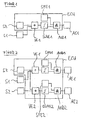
- FIG. 1 shows a central control unit (ECU) with a central sensor unit (SZ), a linking unit (VE1), a threshold comparator unit (SWVW1), an AND gate (AND1) and a safing unit (SFE1). Furthermore, a sensor unit (S1) and a trip unit (AE1) are shown.
- ECU central control unit
- SZ central sensor unit
- VE1 central sensor unit
- SWVW1 threshold comparator unit
- AND1 AND gate
- SFE1 safing unit
- SFE1 safing unit
- the signals of the central sensor unit (SZ) and the raw data transmitting decentralized sensor unit (S1) are fed to the input of the logic unit (VE1).
- the output of the linking unit (VE1) is supplied to the input of the threshold value comparator unit (SWVW1).
- the output of the threshold comparator unit (SWVW1) is fed to the input of the AND gate (AND1).
- the AND gate (AND1) is supplied with the signal output of the safing unit (SFE1).
- the signal output of the AND gate (AND1) is supplied to the signal input of the trip unit 1.
- the linking unit (VE1) forms a sum signal of the signals of the central sensor unit (SZ) and the raw data transmitting sensor unit (S1). Only when a suitable threshold value in the threshold comparator unit (SWVW1) is exceeded and at the same time a suitable safing condition of the safing unit (SFE1) is supplied to the AND gate (AND1), a triggering decision for the occupant protection means is transmitted to the trip unit (AE1) , The trip unit (AE1) then ignites an assigned occupant protection means, such as a side airbag or a belt tensioner.
- SWVW1 threshold comparator unit
- SFE1 a suitable safing condition of the safing unit
- FIG. 2 essentially represents the establishment of the FIG. 1 wherein the device comprises a second sensor unit (S2), a further trip unit (AE2) and corresponding to these units a second link unit (VE2), a second AND gate (AND2), a second safing unit (SFE2) and a second Trip unit (AE2).
- S2 second sensor unit
- AE2 further trip unit
- VE2 second link unit
- VE2 second AND gate
- SFE2 second safing unit
- AE2 second Trip unit
- the first sensor unit (S1) shown represents, for example, an acceleration or pressure satellite in the left half of the vehicle of a motor vehicle
- the first trip unit (AE1) or the second trip unit (AE2) causes the triggering of a left or right side airbag or a left or right belt tensioner.
- FIG. 3 shows a device according to the invention, in contrast to the in FIG. 2 has a third sensor unit (S3) and, associated with it, a third link unit (VE3), a third threshold comparator unit (SWVE3) and a third AND gate (AND3). Furthermore, the in FIG. 3 1, a fourth threshold comparator unit (SWVE32), a fourth AND gate (AND32), and a fourth safing unit (SFE32). The sum signal at the signal output of the third combination unit (VE3) is fed to the fourth threshold value comparator unit (SWVE32). The signal output of this fourth threshold comparator unit (SWVE32) is applied to one input of the fourth AND gate (AND32). Another input of the fourth AND gate (AND32) is connected to the signal output of the fourth safing unit (SFE32).
- the third sensor unit (S3) shown is, for example, an acceleration sensor unit which is mounted in the rear of a motor vehicle and which is sensitive to acceleration in both directions perpendicular to the direction of travel of the motor vehicle.
- the sum signal at the signal output of the third combination unit (VE3) is compared in the third threshold value comparator unit (SWVE3) against a threshold value, the exceeding of which may result in the triggering of a left side airbag.
- the same sum signal at the signal output of the third combination unit (VE3) is compared in the fourth threshold value comparator unit (SWVE32) with a threshold value whose exceeding or undershooting may result in the triggering of a right side airbag.
- a trigger signal of the third threshold comparator unit (SWVE3) is present at the signal input of the third AND gate (AND3) simultaneously with a plausibilizing signal from the third safing unit, the signal is forwarded to the first OR gate (OR1) and from there to the first trip unit (AE1).
- the first trip unit (AE1) thereby triggers a left side airbag.
- a triggering decision from the first AND gate (AND1) on the first OR unit (OR1) to the first trip unit (AE1), which also causes the release of the left side airbag is also effected.
- the functional units of the device according to the invention and the sequence of the invention associated method can be at least partially executed within a computing unit.
Landscapes
- Engineering & Computer Science (AREA)
- Mechanical Engineering (AREA)
- Air Bags (AREA)
Abstract
Description
Die Erfindung betrifft eine Einrichtung und ein Verfahren zur Auslösung eines Insassenschutzmittels in einem Kraftfahrzeug mit einer zentralen Steuereinheit, in der eine zentrale Sensoreinheit angeordnet ist, und mit mindestens einer rohdatenübertragenden Sensoreinheit. Die zentrale Steuereinheit weist für je eine rohdatenübertragende Sensoreinheit eine Verknüpfungseinheit und eine Schwellwertvergleichereinheit auf, wobei das Signal der zentralen Sensoreinheit einem ersten Signaleingang der Verknüpfungseinheit zugeführt ist und das Signal der rohdatenübertragenden Sensoreinheit einem zweiten Signaleingang der Verknüpfungseinheit. Der Signalausgang der Verknüpfungseinheit ist mit der Schwellwertvergleichereinheit verbunden und der Signalausgang der Schwellwertvergleichereinheit ist mit der Auslöseeinheit des der jeweiligen Sensoreinheit zugeordneten Insassenschutzmittels verbunden, so dass die Auslöseeinheit das mit ihr verbundene Insassenschutzmittel dann auslöst, wenn der Signalausgang der Verknüpfungseinheit größer als ein Schwellwert der zugeordneten Schwellwertvergleichereinheit ist.The invention relates to a device and a method for triggering an occupant protection device in a motor vehicle with a central control unit, in which a central sensor unit is arranged, and with at least one raw data transmitting sensor unit. The central control unit has a linking unit and a threshold value comparison unit for each raw data transmitting sensor unit, the signal of the central sensor unit being fed to a first signal input of the linking unit and the signal of the raw data transmitting sensor unit to a second signal input of the linking unit. The signal output of the linking unit is connected to the Schwellwertvergleichereinheit and the signal output of the Schwellwertvergleichereinheit is connected to the trip unit of the respective sensor unit occupant protection means, so that the trip unit then triggers the occupant protection means connected to it when the signal output of the link unit is greater than a threshold value of the associated threshold value comparator unit is.
In vielen Anwendungsgebieten müssen innerhalb eines Kraftfahrzeugs Messsignale von Sensoreinheiten an eine zentrale Recheneinheit übertragen werden. Vor allem auf dem Gebiet des Schutzes von Insassen eines Kraftfahrzeugs werden die Signale von dezentralen Sensoreinheiten an die zentrale Steuereinheit des Kraftfahrzeuges übermittelt. Der bevorzugte Platz zur Anordnung solcher dezentraler Sensoreinheiten, den sogenannten Satelliteneinheiten, ist genau an den Stellen des Kraftfahrzeugs, an denen im Falle eines Aufprallunfalles das am besten auszuwertende Signal zu erwarten ist.In many fields of application, measurement signals from sensor units must be transmitted to a central processing unit within a motor vehicle. Especially in the field of protection of occupants of a motor vehicle, the signals are transmitted from decentralized sensor units to the central control unit of the motor vehicle. The preferred place for the arrangement of such decentralized sensor units, the so-called satellite units, is exactly at the points of the motor vehicle at which, in the event of a collision accident, the best signal to be evaluated is to be expected.
Beispielsweise werden Beschleunigungssensoreinheiten am sogenannten Schweller unterhalb des Fahrzeugsitzes eines Kraftfahrzeugs und in der Nähe der Kraftfahrzeugseitentür angebracht. Werden als Sensoreinheiten Drucksensoreinheiten verwendet, sogenannte Drucksatelliten, so sind diese in einem abgeschlossenen Hohlraum, bevorzugt in den Seitentüren, angeordnet.For example, acceleration sensor units are mounted on the so-called sill below the vehicle seat of a motor vehicle and in the vicinity of the motor vehicle side door. If pressure sensor units are used as sensor units, so-called pressure satellites, these are arranged in a closed cavity, preferably in the side doors.
Eine solche Drucksensoreinheit ist beispielsweise aus dem
Ebenfalls bekannt aus der Druckschrift
Darüber hinaus kann durch die Verwendung mehrerer Sensoreinheiten auch bei solchen Aufprallereignissen des Kraftfahrzeugs eine geeignete Auslöseentscheidung für ein Insassenschutzmittel getroffen werden, bei der das Signal nur einer Sensoreinheit nicht genügend Sicherheit für eine richtige Auslöseentscheidung bietet. Beispielsweise werden durch eine geeignete Anordnung einer Beschleunigungssensoreinheit in der B-Säule eines Kraftfahrzeugs vorzugsweise Aufprallereignisse auf die starre Fahrzeugstruktur des Kraftfahrzeugs detektiert, wohingegen eine Drucksensoreinheit in der Fahrzeugtür vor allem Aufpralle auf die Fahrzeugtür erfassen kann. Werden nun der zentralen Steuereinheit die Signale beider Sensoreinheiten zugeführt, so kann die zentrale Steuereinheit auch Aufprallereignisse auf die starre Fahrzeugstruktur mit Hilfe der Auslöseentscheidung der Beschleunigungssensoreinheit detektieren, die bei alleiniger Verwendung einer Drucksensoreinheit nicht oder nur sehr spät detektierbar wären.In addition, by using a plurality of sensor units even in such impact events of the motor vehicle, a suitable triggering decision for an occupant protection means can be made, in which the signal of only one sensor unit does not provide sufficient security for a correct triggering decision. For example, by a suitable arrangement of an acceleration sensor unit in the B-pillar of a motor vehicle, impact events on the rigid vehicle structure of the motor vehicle are preferably detected, whereas a pressure sensor unit in the vehicle door can primarily detect impacts on the vehicle door. If the signals of both sensor units are now supplied to the central control unit, the central control unit can also detect impact events on the rigid vehicle structure with the aid of the triggering decision of the acceleration sensor unit, which would not be detectable or only detectable very late if a pressure sensor unit were used alone.
Neueste Entwicklungen auf dem Gebiet des Insassenschutzes in Kraftfahrzeugen verwenden sogenannte rohdatenübertragende Sensoreinheiten. In der rohdatenübertragenden Sensoreinheit erfolgt keine Auswertung der gemessenen Sensordaten wie dies bislang üblicherweise oft der Fall war. Die in der rohdatenübertragenden Sensoreinheit enthaltene Elektronik sorgt lediglich dafür, dass die gemessenen Daten auf geeignete Weise an eine zentrale Steuereinheit übermittelt werden können. Eine Auswertung der Sensorsignale erfolgt erst dort.Recent developments in the field of occupant protection in motor vehicles use so-called raw data transmitting sensor units. In the raw data transmitting sensor unit, no evaluation of the measured sensor data takes place, as has hitherto often been the case. The electronics contained in the raw data transmitting sensor unit only ensures that the measured data can be transmitted in a suitable manner to a central control unit. An evaluation of the sensor signals takes place there.
Eine solche rohdatenübertragende Sensoreinheit unter Verwendung eines Drucksensors als Messaufnehmer ist beispielsweise in der
Wie dort beschrieben, werden die gemessenen Sensorwerte durch die Elektronik der Sensoreinheit beispielsweise digitalisiert und als Sieben-Bit-Datenwort mit einer Übertragungsfrequenz von zwei Kilohertz an die zentrale Steuereinheit übermittelt.As described there, the measured sensor values are digitized by the electronics of the sensor unit, for example, and transmitted as a seven-bit data word with a transmission frequency of two kilohertz to the central control unit.
Weiter oben wurde bereits beschrieben, dass zur Messung von Aufprallereignissen an einem Kraftfahrzeug mehrere Sensoreinheiten über das Kraftfahrzeug verteilt angeordnet sein können. Als solche verteilt angeordnete Sensoreinheiten können auch rohdatenübertragende Sensoreinheiten verwendet werden, beispielsweise Drucksensoreinheiten oder Beschleunigungssensoreinheiten.It has already been described above that for measuring impact events on a motor vehicle, a plurality of sensor units can be distributed over the motor vehicle. Sensor units which are distributed as such can also be used as raw data-transmitting sensor units, for example pressure sensor units or acceleration sensor units.
Aus der Offenlegungsschrift
Aufgabe der vorliegenden Erfindung ist es, eine verbesserte Auslöseentscheidung bei der Auslösung von Insassenschutzmitteln in einem Kraftfahrzeug bei der Verwendung von mindestens einer rohdatenübertragenden Sensoreinheit und einer zentral auswertenden zentralen Steuereinheit zu erreichen.Object of the present invention is to achieve an improved triggering decision in the release of occupant protection means in a motor vehicle with the use of at least one raw data transmitting sensor unit and a centrally evaluating central control unit.
Die Aufgabe wird gelöst durch eine Einrichtung mit den Merkmalen des Patentanspruchs 1.The object is achieved by a device having the features of
Die erfindungsgemäße Einrichtung dient zur Auslösung eines Insassenschutzmittels und umfasst eine zentrale Steuereinheit, der die Daten mindestens einer rohdatenübertragenden Sensoreinheit zugeführt werden. Die zentrale Steuereinheit weist eine vorzugsweise in der zentralen Steuereinheit integriert angeordnete zentrale Sensoreinheit auf. Die in der zentralen Steuereinheit angeordnete zentrale Sensoreinheit wird zumeist gebildet aus einem Beschleunigungssensor mit geeigneter elektronischer Beschaltung zur Aufbereitung des Sensorsignals für die weitere Auswertung des Sensorsignals in der zentralen Steuereinheit.The device according to the invention serves for triggering an occupant protection device and comprises a central control unit, to which the data are fed to at least one raw-data-transmitting sensor unit. The central control unit has a central sensor unit, which is preferably integrated in the central control unit. The arranged in the central control unit central sensor unit is usually formed from an acceleration sensor with suitable electronic circuitry for conditioning of the sensor signal for the further evaluation of the sensor signal in the central control unit.
Des Weiteren weist die erfindungsgemäße Einrichtung mindestens eine rohdatenübertragende Sensoreinheit auf.Furthermore, the device according to the invention has at least one raw-data-transmitting sensor unit.
Die rohdatenübertragende Sensoreinheit ist im Gegensatz zur zentralen Sensoreinheit räumlich entfernt von der zentralen Steuereinheit so im Kraftfahrzeug angebracht, dass sie die bei einem Aufprallunfall auftretenden Krafteinwirkungen bestmöglich erfassen kann.The raw data transmitting sensor unit is in contrast to the central sensor unit spatially remote from the central control unit so mounted in the motor vehicle that it can detect the forces occurring in a collision accident effects as best as possible.
Geeignete rohdatenübertragende Sensoreinheiten sind beispielsweise Beschleunigungssensoreinheiten, die an Stellen des Kraftfahrzeugs angebracht sind, an denen eine sehr gute mechanische Kopplung mit der starren Fahrzeugstruktur eines Kraftfahrzeugs gewährleistet ist.Suitable raw data transmitting sensor units are, for example, acceleration sensor units, which are attached to locations of the motor vehicle, where a very good mechanical coupling with the rigid vehicle structure of a motor vehicle is ensured.
Eine weitere geeignete Sensoreinheit ist beispielsweise eine Drucksensoreinheit, die beispielsweise in einer Fahrzeugtür angeordnet ist, um den bei einem Aufprallunfall auftretenden Druckanstieg innerhalb der Fahrzeugtür zu erfassen.Another suitable sensor unit is, for example, a pressure sensor unit, which is arranged, for example, in a vehicle door in order to detect the pressure rise occurring within the vehicle door in the event of a collision accident.
Im Folgenden werden die rohdatenübertragenden Sensoreinheiten auch Satelliteneinheiten, Satelliten oder nur Sensoreinheiten genannt. Wenn sie Drucksensoren oder Beschleunigungssensoren aufweisen, werden sie darüber hinaus auch Beschleunigungssensoreinheiten oder Beschleunigungssatelliten beziehungsweise Drucksensoreinheiten oder Drucksatelliten genannt.In the following, the raw data transmitting sensor units are also called satellite units, satellites or only sensor units. In addition, if they have pressure sensors or acceleration sensors, they are also called acceleration sensor units or acceleration satellites or pressure sensor units or pressure satellites.
Die Signale der Satelliteneinheiten werden in der zentralen Steuereinheit durch eine geeignete Empfangseinheit aufgenommen. Erfindungsgemäß wird das Signal einer Satelliteneinheit allerdings einem Signaleingang einer Verknüpfungseinheit zugeführt, der eingangsseitig zugleich auch das Signal der zentralen Sensoreinheit zugeführt ist.The signals of the satellite units are recorded in the central control unit by a suitable receiving unit. According to the invention, however, the signal of a satellite unit is fed to a signal input of a linking unit, which at the same time is also fed to the signal of the central sensor unit on the input side.
Der Ausgang der Verknüpfungseinheit ist mit einer Schwellwertvergleichereinheit verbunden. Der Ausgang der Schwellwertvergleichereinheit wiederum wird mittelbar oder unmittelbar einer Auslöseeinheit eines zugeordneten Insassenschutzmittels zugeführt. Die Auslöseeinheit kann dabei wie die zentrale Sensoreinheit ebenfalls in der ECU untergebracht sein.The output of the linking unit is connected to a threshold value comparator unit. The output of the threshold value comparator unit in turn is fed directly or indirectly to a tripping unit of an associated occupant protection means. The trip unit can also be accommodated in the ECU as the central sensor unit.
Die beschriebenen Funktionseinheiten innerhalb der zentralen Steuereinheit dienen der Signalaufbereitung wie folgt:
- Die Verknüpfungseinheit bewirkt eine geeignete Verknüpfung der Signale der Satelliteneinheit und der zentralen Sensoreinheit. Im einfachsten Falle wird durch die Verknüpfungseinheit ein Summensignal der Signale der zentralen Sensoreinheit und der Satelliteneinheit erzeugt. Am Signalausgang der Verknüpfungseinheit liegt deshalb für diesen Fall ein Summensignal dieser beiden Sensoreinheiten vor.
- Dieses Summensignal wird durch die Schwellwertvergleichereinheit auf das Überschreiten oder Unterschreiten eines in der Schwellwertvergleichereinheit gespeicherten Schwellwerts geprüft.
- The linking unit effects a suitable combination of the signals of the satellite unit and the central sensor unit. In the simplest case, a summation signal of the signals of the central sensor unit and the satellite unit is generated by the linking unit. Therefore, at the signal output of the linking unit, there is a summation signal of these two sensor units for this case.
- This sum signal is checked by the threshold value comparison unit for the exceeding or falling below a threshold value stored in the threshold value comparison unit.
Üblicherweise wird in einer derartigen Schwellwertvergleichereinheit das eingehende Signal gegen mehrere zeitlich veränderliche und gegebenenfalls signalabhängige Schwellwerte verglichen. Über- oder unterschreitet das der Schwellwertvergleichereinheit zugeführte Summensignal zumindest einen dieser Schwellwerte, so wird der Auslöseeinheit, die mit der Schwellwertvergleichereinheit verbunden ist, eine Auslöseentscheidung übermittelt. Die Auslöseeinheit gibt nun ihrerseits die Auslöseentscheidung der Schwellwertvergleichereinheit direkt an das Insassenschutzmittel weiter, so dass beispielsweise ein Airbag oder ein Gurtstraffer aktiviert wird.Usually, in such a threshold comparator unit the incoming signal is compared against a plurality of time-varying and possibly signal-dependent threshold values. If the sum signal supplied to the threshold value comparator unit exceeds or falls below at least one of these threshold values, then the trip unit, which is connected to the threshold value comparator unit, transmits a triggering decision. The trip unit is then in turn the trip decision of Schwellwertvergleichereinheit directly to the occupant protection means, so that, for example, an airbag or a belt tensioner is activated.
Vorzugsweise umfasst die erfindungsgemäße Einrichtung mindestens drei Satelliteneinheiten, nämlich eine erste, eine zweite und eine dritte Satelliteneinheit mit entsprechend eingangsseitig damit verbundenen ersten, zweiten und dritten Verknüpfungseinheiten, deren Signalausgänge wiederum mit ersten, zweiten und dritten Schwellwertvergleichereinheiten verbunden sind.Preferably, the device according to the invention comprises at least three satellite units, namely a first, a second and a third satellite unit with first, second and third link units correspondingly connected on the input side, the signal outputs of which are in turn connected to first, second and third threshold comparator units.
Die zentrale Sensoreinheit ist ebenfalls mit jeder dieser Verknüpfungseinheiten verbunden, so dass als Signalausgang jeder Verknüpfungseinheit ein Summensignal aus den Signalen der zentralen Sensoreinheit und der jeweiligen Satelliteneinheit erzeugt wird.
Dieses verknüpfte Summensignal wird an die jeweilige Schwellwertvergleichereinheit weitergeleitet, in der jedes derart erzeugte Summensignal mit einem oder mehreren Schwellwerten der jeweiligen Schwellwertvergleichereinheiten verglichen wird. Liegen die Signalausgänge der Verknüpfungseinheiten über oder unter einem gewissen Schwellwert, so teilen die jeweiligen Schwellwertvergleichereinheiten dies den mit ihnen verbundenen Auslöseeinheiten für die zugeordneten Insassenschutzmittel als Auslöseentscheidung mit.The central sensor unit is also connected to each of these linking units, so that a sum signal from the signals of the central sensor unit and the respective satellite unit is generated as the signal output of each linking unit.
This linked sum signal is forwarded to the respective threshold value comparator unit, in which each summation signal generated in this way is compared with one or more threshold values of the respective threshold value comparison units. If the signal outputs of the combination units are above or below a certain threshold value, then the respective threshold comparator units divide this with their associated trip units for the assigned occupant protection as a triggering decision with.
Vorzugsweise ist mindestens eine Satelliteneinheiten eine Beschleunigungssatelliteneinheit, in einer weiteren Ausführungsform ist mindestens eine Satelliteneinheiten ein Drucksatellit.Preferably, at least one satellite unit is an accelerator satellite unit, in another embodiment at least one satellite unit is a pressure satellite.
Eine weitere bevorzugte Ausführungsform der Erfindung besteht darin, dass die erste und die zweite Satelliteneinheit durch Drucksatelliten gebildet werden, die dritte Sensoreinheit hingegen durch einen Beschleunigungssatelliten.A further preferred embodiment of the invention consists in that the first and the second satellite unit are formed by pressure satellites, whereas the third sensor unit is formed by an acceleration satellite.
Beispielsweise sind die beiden Drucksatelliteneinheiten jeweils in den beiden vorderen Seitentüren angeordnet, die Beschleunigungssensoreinheit ist hingegen unter der Fahrzeugrückbank im hinteren Fahrzeugteil mittig an einem starren Karosserieteil befestigt.For example, the two pressure satellite units are each arranged in the two front side doors, the acceleration sensor unit, however, is mounted centrally under the vehicle rear seat in the rear part of the vehicle to a rigid body part.
Auf diese Weise können durch die beiden vorderen Drucksensoreinheiten jeweils Aufprallereignisse detektiert werden, bei denen die vorderen Fahrzeugtüren eingedrückt werden. Sobald jedoch die starre Karosserie des Fahrzeugs durch ein aufprallendes Objekt beschleunigt wird, ohne dass eine der vorderen Fahrzeugtüren eingedrückt werden, so kann das durch die mit der Karosserie fest verbundenen hinteren Beschleunigungseinheit erfasst werden.In this way, each of the two front pressure sensor units impact events can be detected, in which the front vehicle doors are pressed. However, as soon as the rigid body of the vehicle is accelerated by an impacting object, without any of the front vehicle doors being pressed in, this can be detected by the rear acceleration unit fixed to the bodywork.
Durch das erfindungsgemäße jeweilige Auswerten eines Summensignals aus den beiden Drucksatelliteneinheiten mit dem Signal der zentralen Sensoreinheit und des Summensignals der hinteren Beschleunigungssensoreinheit mit dem Signal der zentralen Sensoreinheit wird darüber hinaus eine besonders effektive Detektion von Aufprallereignissen eine Kraftfahrzeuges ermöglicht:By means of the respective evaluation of a sum signal from the two pressure satellite units according to the invention with the signal of the central sensor unit and the sum signal of the rear acceleration sensor unit with the signal of the central sensor unit, a particularly effective detection of impact events of a motor vehicle is made possible:
Zum einen wird die üblicherweise sehr rasche Druckänderung bei der Deformation der Fahrzeugtüren durch die Drucksensoreinheiten erfasst. Durch die Verknüpfung der Signale der Drucksensoreinheiten mit der zentralen Sensoreinheit der zentralen Steuereinheit wird zum anderen ein Signal erzeugt, dass sowohl auf die rasche Deformation der Fahrzeugtüren in sehr schneller Weise anspricht als auch auf eine reine Beschleunigung der starren Fahrzeugstruktur.On the one hand, the usually very rapid pressure change during the deformation of the vehicle doors is detected by the pressure sensor units. By linking the signals of the pressure sensor units with the central sensor unit of the central control unit, on the other hand, a signal is generated which responds both to the rapid deformation of the vehicle doors in a very fast manner and to a pure acceleration of the rigid vehicle structure.
Ein zumindest anfänglich rein beschleunigendes Aufprallereignis ist beispielsweise dann gegeben, wenn ein schmales Objekt, beispielsweise ein Baum, nur auf die B-Säule des Kraftfahrzeugs trifft. Bei einem solchen Aufprallereignis wird lediglich das Fahrzeug als Ganzes mit seiner Karosserie beschleunigt. Eine geringe Deformation der Seitentüre wird erst dann erzeugt, wenn das Aufprallereignis stark genug ist, um das komplette Fahrzeug zu verwinden und somit auch die Seitentür zu deformieren.An at least initially purely accelerating impact event is given, for example, when a narrow object, for example a tree, only hits the B pillar of the motor vehicle. In such an impact event, only the vehicle as a whole is accelerated with its body. A slight deformation of the side door is only generated when the impact event is strong enough to twist the entire vehicle and thus also deform the side door.
Wenn beispielsweise der Baum nur auf die Seitentür trifft, wird in erster Linie zunächst die Fahrzeugtüre so deformiert, das ein sehr rascher Druckanstieg in dem durch die Seitentür gebildeten Hohlraum entsteht. Dieser Druckanstieg wird durch eine in der Seitentür angebrachte Drucksensoreinheit sehr schnell erfasst. Die Beschleunigungssensoreinheit in der zentralen Steuereinheit detektiert dabei erst dann ein ausreichend hohes Signal, wenn der Baum nach der Deformation der Seitentür steife Karosserieteile erfasst und beschleunigt.For example, if the tree meets only the side door, first of all the vehicle door is first deformed in such a way that a very rapid increase in pressure occurs in the cavity formed by the side door. This pressure increase is detected very quickly by a pressure sensor unit mounted in the side door. The acceleration sensor unit in the central control unit only detects a sufficiently high signal when the tree detects and accelerates stiff body parts after the deformation of the side door.
Der Vorteil einer gemeinsamen Auswertung eines verknüpften Signals aus dem Signal der Beschleunigungssensoreinheit und dem Signal einer Drucksensoreinheit in den Seitentüren des Kraftfahrzeugs besteht darin, dass ein geeignet gewählter Schwellwert für das verknüpfte Signal in der zugeordneten Schwellwertvergleichereinheit sowohl in einem zunächst rein beschleunigenden Aufprallunfall als auch in einem anfänglich zunächst rein deformierenden Aufprallunfall erreicht werden kann.The advantage of a joint evaluation of a linked signal from the signal of the acceleration sensor unit and the signal of a pressure sensor unit in the side doors of the motor vehicle is that a suitably selected threshold value for the associated signal in the associated threshold comparator unit both in an initially purely accelerating crash accident and in a initially initially purely deforming collision accident can be achieved.
Da die Schwellwertvergleichereinheit mittelbar oder unmittelbar mit der Auslöseeinheit des zugeordneten Insassenschutzmittels, beispielsweise eines Seitenairbags verbunden ist, kann mit Hilfe eines verknüpften Signals einer Satelliteneinheit mit der zentralen Sensoreinheit die jeweils schnellste Auslösung des am besten für diese Art des Unfalls geeigneten Insassenschutzmittels herbeigeführt werden.Since the threshold value comparator unit is directly or indirectly connected to the trigger unit of the assigned occupant protection means, for example a side airbag, the fastest deployment of the occupant protection means most suitable for this type of accident can be brought about by means of a linked signal of a satellite unit with the central sensor unit.
Das Signal der dritten Beschleunigungssensoreinheit, deren Signal in der ihr zugeordneten Verknüpfungseinheit ebenfalls mit dem Signal der zentralen Sensoreinheit verknüpft wird, können nun dazu benutzt werden, auf ähnliche Weise schnelle und sichere Auslöseentscheidungen eines Seitenairbags dann herbeizuführen, wenn vor allem starre Karosserieteile des hinteren Fahrzeugteils durch ein aufprallendes Objekt getroffen werden.The signal of the third acceleration sensor unit whose signal is also linked in its associated linking unit with the signal of the central sensor unit, can now be used to similarly cause fast and safe triggering decisions of a side airbag, especially if rigid body parts of the rear vehicle part an impacting object is hit.
Die zentrale Sensoreinheit in der zentralen Steuereinheit wird bei einem solchen Aufprallunfall ebenfalls ein seitliches Beschleunigungssignal feststellen können, da auch die zentrale Sensoreinheit bzw. die sie umgebende zentrale Steuereinheit fest mit der Fahrzeugkarosserie verbunden sind. Eine Verknüpfung der beiden Beschleunigungssignale der zentralen Sensoreinheit und des hinteren Beschleunigungssatelliten führt daher zu einem verstärkten Beschleunigungssignal, das deshalb zu einer sichereren, deutlichen und schnellen Überschreitung des Schwellwerts in der zugeordneten Schwellwertvergleichereinheit und deshalb auch im Falle eines hinteren Aufprallunfalls führt.The central sensor unit in the central control unit will also be able to detect a lateral acceleration signal in the event of such an impact accident since the central sensor unit or the central control unit surrounding it is also firmly connected to the vehicle body. A combination of the two acceleration signals of the central sensor unit and the rear acceleration satellite therefore leads to an amplified acceleration signal, which therefore leads to a safer, clear and rapid exceeding of the threshold value in the associated threshold comparator unit and therefore also in the case of a rear impact accident.
Vorteilhafterweise ist die dritte Verknüpfungseinheit der dritten Sensoreinheit ausgangsseitig gleichzeitig mit der dritten Schwellwertvergleichereinheit und einer vierten Schwellwertvergleichereinheit verbunden, wobei der Signalausgang der dritten Schwellwertvergleichereinheit mit der ersten Auslöseeinheit verbunden ist, jedoch der Signalausgang der vierten Schwellwertvergleichereinheit mit der zweiten Auslöseeinheit. Dies ermöglicht die Ansteuerung verschiedener Insassenschutzmittel, sobald durch die Schwellwertvergleichereinheiten ein Über- oder Unterschreiten des zugeordneten Schwellwerts feststellt wird.Advantageously, the third linking unit of the third sensor unit is connected on the output side simultaneously to the third threshold comparator unit and a fourth threshold comparator unit, wherein the signal output of the third threshold comparator unit is connected to the first trip unit, but the signal output of the fourth threshold comparator unit to the second trip unit. This makes it possible to control various occupant protection means as soon as the associated threshold value is ascertained by the threshold value comparison units.
Beispielsweise kann die dritte Beschleunigungssensoreinheit sowohl positive als auch negative Beschleunigungen senkrecht zur Fahrtrichtung des Kraftfahrzeugs erfassen. Vorteilhafterweise übermittelt die dritte Schwellwertvergleichereinheit folglich das Überschreiten und die vierte Schwellwertvergleichereinheit das Unterschreiten eines Schwellwerts als Auslösekriterium zur Auslösung eines Seitenairbags für die eine Fahrzeugseite bzw. die andere Fahrzeugseite.For example, the third acceleration sensor unit detect both positive and negative accelerations perpendicular to the direction of travel of the motor vehicle. Advantageously, the third threshold comparator unit consequently transmits the exceeding and the fourth threshold comparator unit drops below a threshold value as a triggering criterion for triggering a side airbag for the one vehicle side or the other vehicle side.
Vorzugsweise werden die Signalausgänge der dritten und er vierten Schwellwertvergleichereinheiten, die das Summensignal aus den Signalen der hinteren Beschleunigungssensoreinheit und der zentralen Sensoreinheit bewerten, durch ein ODER-Gatter mit den Signalausgängen der Schwellwertvergleichereinheiten zusammengeführt, die der gleichen Auslöseeinheit eines Insassenschutzmittels zugeordnet sind. So führt beispielsweise ein Summensignal der zentralen Sensoreinheit und der hinteren Beschleunigungssensoreinheit oder das Summensignal der vorderen Drucksensoreinheit und der zentralen Sensoreinheit, die beide beispielsweise der Auslöseeinheit für einen linken Seitenairbag zugeordnet sind, unabhängig voneinander zu einer Auslöseentscheidung des linken Seitenairbags.Preferably, the signal outputs of the third and fourth threshold comparator units, which evaluate the sum signal from the signals of the rear acceleration sensor unit and the central sensor unit, are ORed with the signal outputs of the threshold comparator units associated with the same trip unit of an occupant protection means. For example, a sum signal of the central sensor unit and the rear acceleration sensor unit or the sum signal of the front pressure sensor unit and the central sensor unit, both of which are associated with, for example, the left side airbag trip unit, independently causes a triggering decision of the left side airbag.
Es sind zwischen den Schwellwertvergleichereinheiten und den Auslöseeinheiten UND-Gatter angeordnet, so dass die Signalausgänge der Schwellwertvergleichereinheiten jeweils den Signaleingängen der UND-Gatter zugeführt sind. Einem oder mehreren weiteren Signaleingängen der UND-Gatter sind die Signalausgänge jeweils zugeordneter Safing-Einheiten zugeführt. Nur wenn gleichzeitig Signale der Schwellwertvergleichereinheiten und der Safing-Einheiten am UND-Gatter vorliegen, so wird die Auslöseentscheidung der Schwellwertvergleichereinheiten am Signalausgang der jeweiligen UND-Gatter ausgegeben und damit der jeweils angeschlossenen Auslöseeinheit ein Befehl zur Auslösung eines geeigneten Insassenschutzmittels weitergegeben.There are AND gates between the threshold comparator units and the trip units, so that the signal outputs of the threshold comparator units are respectively supplied to the signal inputs of the AND gates. One or more further signal inputs of the AND gates are supplied with the signal outputs of respectively assigned safing units. Only if there are signals of the threshold comparator units and the safing units at the AND gate at the same time, the trigger decision of Schwellwertvergleichereinheiten at the signal output of the respective AND gate is output and thus the connected trigger unit passed a command to trigger a suitable occupant protection means.
Als Signalausgänge der Safing-Einheiten werden die Ergebnisse weiterer Auswertungen der zugeführten Sensordaten der Satelliteneinheiten und der zentralen Sensoreinheit verwendet, die die Plausibilität der Signale überprüfen sollen.As signal outputs of the safing units, the results of further evaluations of the supplied sensor data of the satellite units and the central sensor unit are used, which are to check the plausibility of the signals.
Im einfachsten Fall überprüft die Safingeinheit, ob die der zentralen Steuerreinheit vorliegenden einzelnen Signale der Sensoreinheiten alleine schon über einem vergleichsweise geringen Schwellwert liegen.In the simplest case, the safing unit checks whether the individual signals of the sensor units present to the central control unit alone are already above a comparatively low threshold value.
Beispielsweise kann die einer linken Beschleunigungssensoreinheit zugeordnete Safing-Einheit als Plausibilitätstest aber auch überprüfen, ob gleichzeitig zu den Sensordaten der linken Beschleunigungssensoreinheit auch passende, aber vorzeichenvertauschte Daten der rechten Beschleunigungssensoreinheit vorliegen oder umgekehrt. Gegebenenfalls kann eine Safing-Einheit auch überprüfen, ob zu einer im Heck des Kraftfahrzeugs angeordneten Beschleunigungssensoreinheit gleichzeitig ein plausibles Signal auch in der zentralen Sensoreinheit erzeugt wird.For example, the safety unit associated with a left-hand acceleration sensor unit can also check as a plausibility test whether matching but signed data of the right-hand acceleration sensor unit are present simultaneously with the sensor data of the left acceleration sensor unit or vice versa. Optionally, a safing unit can also check whether a plausible signal is also generated in the central sensor unit at the same time as an acceleration sensor unit arranged in the rear of the motor vehicle.
Weiterhin kann die Safingeinheit durch Differenzbildung der Sensorwerte aus der zentralen Sensoreinheit und einer im Fahrzeugheck angebrachten Beschleunigungssensoreinheit die Richtung bestimmen, aus der ein aufprallendes Objekt auf ein Fahrzeugheck oder auf die vordere seitliche Fahrzeughälfte auftrifft.Furthermore, by subtracting the sensor values from the central sensor unit and an acceleration sensor unit mounted in the rear of the vehicle, the safing unit can determine the direction from which an impacting object impinges on a vehicle rear or on the front side of the vehicle.
Auch ein solches in der Safingeinheit erzeugtes Differenzsignal kann zur Überprüfung der Richtigkeit beispielsweise des Summensignals aus dem Signal der im Fahrzeugheck angebrachten Satelliteneinheit und der zentralen Sensoreinheit verwendet werden. Dazu wird das Differenzsignal, beispielsweise in der Safingeinheit, gegen einen geeigneten Schwellwert verglichen. Anschließend wird es wie die bereits beschriebenen anderen möglichen plausibilisierenden Signale einer Safingeinheit dem Signaleingang der UND - Einheit zugeführt, die mit der im Fahrzeugheck angebrachten Beschleunigungssensoreinheit verbunden ist.Such a difference signal generated in the safing unit can also be used to check the correctness of, for example, the sum signal from the signal of the vehicle-mounted satellite unit and the central sensor unit. For this purpose, the difference signal, for example in the safing unit, is compared against a suitable threshold value. Subsequently, like the other possible plausibilizing signals of a safing unit already described, it is fed to the signal input of the AND unit, which is connected to the acceleration sensor unit mounted in the rear of the vehicle.
Ein geeignetes Verfahren zur Auslösung eines Insassenschutzmittels in einem Kraftfahrzeug unter Verwendung der erfindungsgemäßen Einrichtung läuft wie folgt ab:A suitable method for triggering an occupant protection device in a motor vehicle using the device according to the invention is as follows:
Eine Verknüpfungseinheit gibt ein aus dem Signal der zentralen Sensoreinheit und dem Signal einer rohdatenübertragenden Sensoreinheit verknüpftes Signal an eine Schwellwertvergleichereinheit weiter, in der dieses verknüpfte Signal mit einem Schwellwert verglichen wird. Die Auslöseentscheidung eines Insassenschutzmittels wird nur dann von der Schwellwertvergleichereinheit an eine zugeordnete Auslöseeinheit gegeben, wenn ein der Schwellwert unterschritten oder überschritten wird.A linking unit forwards a signal linked from the signal of the central sensor unit and the signal of a raw-data-transmitting sensor unit to a threshold-value comparator unit, in which this linked signal is compared with a threshold value. The tripping decision of an occupant protection device is only given by the threshold value comparator unit to an assigned tripping unit if one of the threshold value is undershot or exceeded.
Vorzugsweise wird das Signal jeder Schwellwertvergleichereinheit zunächst einem UND-Gatter zugeführt. Einem weiteren Eingang des UND-Gatters wird das Ausgangssignal einer zugeordneten Safing-Einheit zugeführt, so dass die Auslöseentscheidung der Schwellwertvergleichereinheit nur dann einer Auslöseeinheit eines Insassenschutzmittels übermittelt wird, wenn sowohl ein dazu geeignetes Signal von der Schwellwertvergleichereinheit als auch von der zugeordneten Safing-Einheit am UND-Gatter eingangsseitig anliegt.Preferably, the signal of each threshold comparator unit is first supplied to an AND gate. A further input of the AND gate, the output signal of an associated safing unit is supplied, so that the triggering decision of the Schwellwertvergleichereinheit is only a trip unit of occupant protection means transmitted when both a suitable signal from the threshold comparator unit and the associated safing unit on AND gate on the input side.
Vorzugsweise werden die Auslöseentscheidungen verschiedener Schwellwertvergleichereinheiten über ein ODER-Gatter so miteinander verbunden, dass die den beiden Schwellwertvergleichereinheiten zugeordnete Auslöseeinheit ein Insassenschutzmittel nur dann auslösen kann, wenn entweder die eine oder die andere der mindestens zwei dem ODER-Gatter zugeführten Schwellwertvergleichereinheiten dem ODER-Gatter eine Auslöseentscheidung übermittelt.Preferably, the trigger decisions of different threshold comparator units are interconnected via an OR gate such that the tripping unit associated with the two threshold comparator units can only trigger occupant protection if either one or the other of the at least two threshold comparator units supplied to the OR gate provides the OR gate with an OR gate Trigger decision transmitted.
Im Folgenden wird die Erfindung anhand von drei Ausführungsbeispielen beschrieben.
Es zeigen:
Figur 1- eine erfindungsgemäße Einrichtung mit einer rohdatenübertragenden Sensoreinheit (S1) und einer Auslöseentscheidungseinheit (AE1),
Figur 2- eine erfindungsgemäße mit zwei rohdatenübertragenden Sensoreinheiten (S1, S2) und zwei Auslöseeinheiten (AE1, AE2) und
Figur 3- eine erfindungsgemäße Einrichtung mit drei rohdatenübertragenden Sensoreinheiten (S1, S2, S3) und zwei Auslöseeinheiten (AE1, AE2).
Show it:
- FIG. 1
- a device according to the invention with a raw data transmitting sensor unit (S1) and a trigger decision unit (AE1),
- FIG. 2
- an inventive with two raw data transmitting sensor units (S1, S2) and two trip units (AE1, AE2) and
- FIG. 3
- a device according to the invention with three raw data transmitting sensor units (S1, S2, S3) and two trip units (AE1, AE2).
Die Signale der zentralen Sensoreinheit (SZ) und der rohdatenübertragenden dezentralen Sensoreinheit (S1) sind dem Eingang der Verknüpfungseinheit (VE1) zugeführt. Der Ausgang der Verknüpfungseinheit (VE1) ist dem Eingang der Schwellwertvergleichereinheit (SWVW1) zugeführt. Der Ausgang der Schwellwertvergleichereinheit (SWVW1) ist dem Eingang des UND-Gatters (AND1) zugeführt. Gleichzeitig ist dem UND-Gatter (AND1) der Signalausgang der Safing-Einheit (SFE1) zugeführt. Der Signalausgang des UND-Gatters (AND1) ist dem Signaleingang der Auslöseeinheit 1 zugeführt.The signals of the central sensor unit (SZ) and the raw data transmitting decentralized sensor unit (S1) are fed to the input of the logic unit (VE1). The output of the linking unit (VE1) is supplied to the input of the threshold value comparator unit (SWVW1). The output of the threshold comparator unit (SWVW1) is fed to the input of the AND gate (AND1). At the same time, the AND gate (AND1) is supplied with the signal output of the safing unit (SFE1). The signal output of the AND gate (AND1) is supplied to the signal input of the
Die Verknüpfungseinheit (VE1) bildet ein Summensignal der Signale der zentralen Sensoreinheit (SZ) und der rohdatenübertragenden Sensoreinheit (S1). Nur wenn ein geeigneter Schwellwert in der Schwellwertvergleichereinheit (SWVW1) überschritten wird und gleichzeitig eine geeignete Safing-Bedingung der Safing-Einheit (SFE1) dem UND-Gatter (AND1) zugeführt wird, wird eine Auslöseentscheidung für das Insassenschutzmittel an die Auslöseeinheit (AE1) übermittelt. Die Auslöseeinheit (AE1) zündet daraufhin ein ihr zugeordnetes Insassenschutzmittel, beispielsweise einen Seitenairbag oder auch einen Gurtstraffer.The linking unit (VE1) forms a sum signal of the signals of the central sensor unit (SZ) and the raw data transmitting sensor unit (S1). Only when a suitable threshold value in the threshold comparator unit (SWVW1) is exceeded and at the same time a suitable safing condition of the safing unit (SFE1) is supplied to the AND gate (AND1), a triggering decision for the occupant protection means is transmitted to the trip unit (AE1) , The trip unit (AE1) then ignites an assigned occupant protection means, such as a side airbag or a belt tensioner.
Der Signalverlauf und die Funktionsweise der dargestellten Funktionseinheiten im Signalverlauf der zweiten Sensoreinheit (S2) bis zur zweiten Auslöseeinheit (AE2) ist analog zu der in
Die gezeigte erste Sensoreinheit (S1) stellt beispielsweiseeinen Beschleunigungs- oder Drucksatelliten in der linken Fahrzeughälfte eines Kraftfahrzeugs dar, die zweite Sensoreinheit (S2) einen Beschleunigungs- oder Drucksatelliten in der rechten Fahrzeughälfte. Entsprechend bewirkt die erste Auslöseeinheit (AE1) bzw. die zweite Auslöseeinheit (AE2) die Auslösung eines linken bzw. rechten Seitenairbags oder auch eines linken bzw. rechten Gurtstraffers.The first sensor unit (S1) shown represents, for example, an acceleration or pressure satellite in the left half of the vehicle of a motor vehicle, the second sensor unit (S2) an acceleration or pressure satellite in the right half of the vehicle. Accordingly, the first trip unit (AE1) or the second trip unit (AE2) causes the triggering of a left or right side airbag or a left or right belt tensioner.
Die gezeigte dritte Sensoreinheit (S3) ist beispielsweise eine Beschleunigungssensoreinheit, die im Heck eines Kraftfahrzeuges angebracht ist und die beschleunigungsempfindlich in beide Richtungen senkrecht zur Fahrtrichtung des Kraftfahrzeugs ist.The third sensor unit (S3) shown is, for example, an acceleration sensor unit which is mounted in the rear of a motor vehicle and which is sensitive to acceleration in both directions perpendicular to the direction of travel of the motor vehicle.
Das Summensignal am Signalausgang der dritten Verknüpfungseinheit (VE3) wird in der dritten Schwellwertvergleichereinheit (SWVE3) gegen einen Schwellwert verglichen, dessen Überschreiten gegebenenfalls die Auslösung eines linken Seitenairbags zur Folge hat.The sum signal at the signal output of the third combination unit (VE3) is compared in the third threshold value comparator unit (SWVE3) against a threshold value, the exceeding of which may result in the triggering of a left side airbag.
Das gleiche Summensignal am Signalausgang der dritten Verknüpfungseinheit (VE3) wird in der vierten Schwellwertvergleichereinheit (SWVE32) mit einem Schwellwert verglichen, dessen Überschreiten bzw. Unterschreiten gegebenenfalls die Auslösung eines rechten Seitenairbags zur Folge hat.The same sum signal at the signal output of the third combination unit (VE3) is compared in the fourth threshold value comparator unit (SWVE32) with a threshold value whose exceeding or undershooting may result in the triggering of a right side airbag.
Liegt folglich am Signaleingang des dritten UND-Gatters (AND3) ein Auslösesignal der dritten Schwellwertvergleichereinheit (SWVE3) gleichzeitig mit einem plausibilisierenden Signal aus der dritten Safing-Einheit vor, so wird das Signal weitergeleitet an das erste ODER-Gatter (OR1) und von dort an die erste Auslöseeinheit (AE1). Die erste Auslöseeinheit (AE1) löst dadurch einen linken Seitenairbag aus.
Wie bereits anhand von
As already on the basis of
In gleicher Weise bewirkt eine Auslöseentscheidung am Signalausgang der vierten UND-Einheit (AND32) oder der zweiten UND-Einheit (AND2), die beide jeweils über die zweite ODER-Einheit (OR2) mit der zweiten Auslöseeinheit (AE2) verbunden sind zu einer Auslösung des rechten Seitenairbags.In the same way causes a triggering decision at the signal output of the fourth AND unit (AND32) or the second AND unit (AND2), both of which in each case via the second OR unit (OR2) with the second trip unit (AE2) are connected to a trigger the right side airbag.
Die Funktionseinheiten der erfindungsgemäßen Einrichtung und der erfindungsgemäße Ablauf des zugehörigen Verfahrens können zumindest teilweise auch innerhalb einer Recheneinheit ausgeführt sein.The functional units of the device according to the invention and the sequence of the invention associated method can be at least partially executed within a computing unit.
Claims (9)
- Device for triggering an occupant protection means in a motor vehicle- with a central control unit (ECU), which features a central sensor unit (SZ) and- with at least one sensor unit (S1; S2; S3) transmitting raw data, of which the signal is included for comparison with an associated threshold value and the result of this comparison serves as a trigger criterion for the triggering of the occupant protection means,with, for each sensor unit (S1; S2; S3) transmitting raw data- the central control unit (ECU) having a logic unit (VE1; VE2; VE3) and a threshold value comparison unit (SWVE1; SWVE2; SWVE3, SWVE32),- the signal of the central sensor unit (SZ) being fed to a first signal input of the logic unit (VE1; VE2; VE3),- the signal of the sensor unit (S1; S2; S3) being fed to a second signal input of the logic unit (VE1; VE2; VE3),- the signal output of the logic unit (VE1; VE2; VE3) is connected to the threshold value comparator unit (SWVE1; SWVE2; SWVE3, SWVE32) and- the signal output of the threshold value comparator unit (SWVE1; SWVE2; SWVE3, SWVE32) being connected to the trigger unit (AE1; AE2) of the respective occupant protection means assigned to the sensor unit (S1, S2, S3), so that the trigger unit (AE1; AE2) triggers the occupant protection means connected to it if the signal output of the logic unit (VE1; VE2; VE3) is greater than or less than a threshold value of the assigned threshold value comparator unit (SWVE1; SWVE2; SWVE3, SWVE32).with,
For each threshold value comparator unit (SWVE1; SWVE2; SWVE3, SWVE32) the device having an AND gate (AND1; AND2; AND3, AND32) and at least one safing unit (SFE1; SFE2; SFE3, SFE32), with the AND gate- being connected directly on its input side via a line to the signal output of the threshold value comparator unit (SWVE1; SWVE2; SWVE3, SWVE32),- being furthermore connected on its input side at least to the safing unit (SFE1; SFE2; SFE3, SFE32) and- the AND gate being connected indirectly or directly on the output side to the respective assigned trigger unit (AE1; AE2),so that a triggering of an occupant protection means by the assigned trigger unit (AE1; AE2) can only take place if the signal output of the assigned logic unit (VE1; VE2; VE3; VE32) is greater than or less than a threshold value of the assigned threshold value comparator unit (SWVE1; SWVE2; SWVE3, SWVE32) and simultaneously a further signal of the safing unit (SFE1; SFE2; SFE3, SFE32) is present. - Device in accordance with claim 1, characterised in that, the central sensor unit (SZ) is an acceleration sensor unit (SZ), with a sensing sensitivity at right angles to the direction of travel of the motor vehicle.
- Device in accordance with claim 1 or 2, characterised in that,
the device features at least three sensor units, namely- a first sensor unit (S1), which is connected to a first logic unit (VE1), a first threshold value comparator unit (SWV1) and a first trigger unit (AE1),- a second sensor unit (S2), which is connected to a second logic unit (VE2), a second threshold value comparator unit (SWV2) and a second trigger unit (AE2) and- a third sensor unit (S2), which is connected to a third logic unit (VE3), a third threshold value comparator unit (SWV3), the first trigger unit (AE1) and/or the second trigger unit (AE2). - Device in accordance with one of the claims 1 to 3,
characterised in that,
at least one sensor unit (S1; S2; S3) is an acceleration sensor unit, with a sensing sensitivity at right angles to the direction of travel of the motor vehicle. - Device in accordance with one of the claims 1 to 4,
characterised in that,
at least one sensor unit (S1; S2; S3) is a pressure sensor unit. - Device according to one of claims 3 to 5, characterised in that,
the first and the second sensor unit (S1, S2) are each pressure sensor units, whereas the third sensor unit (S3) is an acceleration sensor unit. - Device in accordance with one of the claims 3 to 6,
characterised in that
the device features a forth threshold value comparator unit (SWVE32),
which is connected on its input side to the third logic unit (VE3) and which is connected on its output side to the first or the second trigger unit (AE1, AE2),
so that the first or the second trigger unit (AE1, AE2) triggers the occupant protection means associated with it in each case if the signal output of the third logic unit (VE3) is greater than or less than a threshold value of the fourth threshold value comparator unit (SVE4). - Device in accordance with one of the claims 3 to 7,
characterised in that
the device features a first OR gate (OR1),- of which the signal inputs are connected to the signal outputs of the first threshold value comparator unit (SWVE1) and the third threshold value comparator unit (SWVE3) and- of which the signal output is connected to the first trigger unit (AE1). - Device in accordance with one of the claims 3 to 8,
characterised in that
the device features a second OR gate (OR2),- of which the signal inputs are connected to the signal outputs of the second threshold value comparator unit (SWVE2) and the fourth threshold value comparator unit (SWVE4) and- of which the signal output is connected to the second trigger unit (AE2).
Applications Claiming Priority (5)
| Application Number | Priority Date | Filing Date | Title |
|---|---|---|---|
| DE10136224A DE10136224A1 (en) | 2001-07-25 | 2001-07-25 | Automobile passenger restraint triggering device combines raw data from external sensor unit with data from central sensor unit before threshold comparison for providing triggering signal |
| DE10136226 | 2001-07-25 | ||
| DE10136226 | 2001-07-25 | ||
| DE10136224 | 2001-07-25 | ||
| PCT/DE2002/002740 WO2003011652A1 (en) | 2001-07-25 | 2002-07-25 | Device and method for triggering a passenger protection means in a motor vehicle |
Publications (3)
| Publication Number | Publication Date |
|---|---|
| EP1409298A1 EP1409298A1 (en) | 2004-04-21 |
| EP1409298B1 EP1409298B1 (en) | 2006-01-11 |
| EP1409298B2 true EP1409298B2 (en) | 2008-12-03 |
Family
ID=26009777
Family Applications (1)
| Application Number | Title | Priority Date | Filing Date |
|---|---|---|---|
| EP02754441A Expired - Lifetime EP1409298B2 (en) | 2001-07-25 | 2002-07-25 | Device and method for triggering a passenger protection means in a motor vehicle |
Country Status (3)
| Country | Link |
|---|---|
| EP (1) | EP1409298B2 (en) |
| DE (2) | DE50205598D1 (en) |
| WO (1) | WO2003011652A1 (en) |
Families Citing this family (5)
| Publication number | Priority date | Publication date | Assignee | Title |
|---|---|---|---|---|
| DE10152749A1 (en) * | 2001-10-25 | 2003-05-08 | Bayerische Motoren Werke Ag | Method for triggering a vehicle occupant restraint |
| DE10361095A1 (en) * | 2003-12-22 | 2005-07-21 | Conti Temic Microelectronic Gmbh | Occupant protection system for vehicle, comprising reduced number of auxiliary sensors |
| DE102006026239B4 (en) * | 2005-06-07 | 2008-04-17 | Denso Corp., Kariya | Occupant protection apparatus and method for protecting an occupant |
| EP2045144A1 (en) * | 2007-10-02 | 2009-04-08 | Continental Automotive GmbH | Method for identifying the collision side in a frontal impact |
| DE102009056617B4 (en) * | 2009-12-02 | 2017-07-13 | Audi Ag | Motor vehicle with a device for detecting a side impact |
Citations (5)
| Publication number | Priority date | Publication date | Assignee | Title |
|---|---|---|---|---|
| DE4322488A1 (en) † | 1992-11-11 | 1994-05-19 | Siemens Ag | Control unit with an air pressure detector for a vehicle occupant protection system |
| DE19514082C1 (en) † | 1995-04-13 | 1996-06-20 | Siemens Ag | Arrangement for triggering a personal protection system |
| DE19645079A1 (en) † | 1996-10-31 | 1998-05-07 | Siemens Ag | Control arrangement for an occupant protection system for side impact protection in a vehicle |
| EP0982199A1 (en) † | 1997-05-16 | 2000-03-01 | Autolive Japan Ltd. | Actuation controller for air bag device |
| DE10008237A1 (en) † | 1999-02-26 | 2000-09-07 | Airbag Systems Co Ltd | Automobile passenger safety restraint control device uses signals from separate acceleration sensors positioned within passenger space and at front of vehicle for rapid response to frontal impact |
Family Cites Families (4)
| Publication number | Priority date | Publication date | Assignee | Title |
|---|---|---|---|---|
| JP2605922B2 (en) * | 1990-04-18 | 1997-04-30 | 日産自動車株式会社 | Vehicle safety devices |
| US5964816A (en) * | 1998-01-26 | 1999-10-12 | Delco Electronics Corp. | Address communication method for a distributed architecture supplemental inflatable restraint system |
| DE10129945B4 (en) * | 2000-08-02 | 2008-11-13 | Continental Automotive Gmbh | Method and arrangement for data transmission in a motor vehicle |
| DE10119781C1 (en) * | 2001-04-23 | 2002-08-22 | Siemens Ag | Control unit and method for detecting the type of impact in an occupant protection system |
-
2002
- 2002-07-25 EP EP02754441A patent/EP1409298B2/en not_active Expired - Lifetime
- 2002-07-25 DE DE50205598T patent/DE50205598D1/en not_active Expired - Lifetime
- 2002-07-25 DE DE20221542U patent/DE20221542U1/en not_active Expired - Lifetime
- 2002-07-25 WO PCT/DE2002/002740 patent/WO2003011652A1/en not_active Application Discontinuation
Patent Citations (5)
| Publication number | Priority date | Publication date | Assignee | Title |
|---|---|---|---|---|
| DE4322488A1 (en) † | 1992-11-11 | 1994-05-19 | Siemens Ag | Control unit with an air pressure detector for a vehicle occupant protection system |
| DE19514082C1 (en) † | 1995-04-13 | 1996-06-20 | Siemens Ag | Arrangement for triggering a personal protection system |
| DE19645079A1 (en) † | 1996-10-31 | 1998-05-07 | Siemens Ag | Control arrangement for an occupant protection system for side impact protection in a vehicle |
| EP0982199A1 (en) † | 1997-05-16 | 2000-03-01 | Autolive Japan Ltd. | Actuation controller for air bag device |
| DE10008237A1 (en) † | 1999-02-26 | 2000-09-07 | Airbag Systems Co Ltd | Automobile passenger safety restraint control device uses signals from separate acceleration sensors positioned within passenger space and at front of vehicle for rapid response to frontal impact |
Also Published As
| Publication number | Publication date |
|---|---|
| DE20221542U1 (en) | 2006-04-13 |
| DE50205598D1 (en) | 2006-04-06 |
| EP1409298A1 (en) | 2004-04-21 |
| WO2003011652A1 (en) | 2003-02-13 |
| EP1409298B1 (en) | 2006-01-11 |
Similar Documents
| Publication | Publication Date | Title |
|---|---|---|
| EP0342401B1 (en) | Device for triggering a passive safety system | |
| EP0693404B1 (en) | Method for deploying side air bags of a passive safety device in a motor vehicle | |
| EP2504201B1 (en) | Method and control unit for recognising the width of a crasharea of a vehicles front. | |
| WO2004008174A1 (en) | Device for monitoring the surroundings of a vehicle | |
| DE10149112A1 (en) | Method for determining a triggering decision for restraint devices in a vehicle | |
| EP1607273A1 (en) | Device and method for detection of an accident in a motor vehicle | |
| EP0866971A1 (en) | Motor vehicle sensor arrangement for detecting an impact | |
| DE19537546B4 (en) | Impact detection device, in particular for a security system for vehicles for the transportation of people | |
| DE102004024265B4 (en) | Security system for operating at least one electrically operable closure device of a door of a vehicle | |
| EP1420983A2 (en) | Method for triggering at least one airbag in a vehicle | |
| WO2004076241A1 (en) | Sensor arrangement for the detection of collisions | |
| EP1648745B1 (en) | Device and method for measuring accelerations for a passenger protection system in a vehicle | |
| EP1542886B1 (en) | Method for the detection of an impact | |
| EP2240346B1 (en) | Method and control device for controlling personal protection means for a vehicle | |
| EP1409298B2 (en) | Device and method for triggering a passenger protection means in a motor vehicle | |
| DE102005033937B4 (en) | Method and device for controlling personal protective equipment | |
| DE19909296A1 (en) | Motor vehicle occupant protection system | |
| DE102007046982B3 (en) | Accident situation i.e. motor vehicle collision, detecting device for protecting passenger, has evaluation unit verifying whether functionality of rotational speed sensor is impaired based on sound detected by impact sound receiver unit | |
| EP1846271B1 (en) | Safety system | |
| DE102005011103B4 (en) | Method and device for detecting a rollover process | |
| EP1731375B1 (en) | Method for classifying a collision event | |
| DE102020205580A1 (en) | Method for determining a type of collision of a vehicle | |
| DE102009000158A1 (en) | Sensor arrangement for detecting impact of object on sport utility vehicle, has sensors comprising distance detection arrangement to detect change of distance between detection electrode and structure electrode by voltage | |
| DE102006038837A1 (en) | Collision detection device for use in vehicle, has occupant sensor, which produces signal that represents weight of occupants, where evaluation circuit e.g. microcontroller, detects collision based on temporal changes of signals | |
| DE102006030563A1 (en) | Sensor unit for use in protective system, has two independent sensor components that output signal with different signs based on physical parameter detected in opposite directions, where signals are separated from each other and evaluated |
Legal Events
| Date | Code | Title | Description |
|---|---|---|---|
| PUAI | Public reference made under article 153(3) epc to a published international application that has entered the european phase |
Free format text: ORIGINAL CODE: 0009012 |
|
| 17P | Request for examination filed |
Effective date: 20031205 |
|
| AK | Designated contracting states |
Kind code of ref document: A1 Designated state(s): AT BE BG CH CY CZ DE DK EE ES FI FR GB GR IE IT LI LU MC NL PT SE SK TR |
|
| 17Q | First examination report despatched |
Effective date: 20040630 |
|
| GRAP | Despatch of communication of intention to grant a patent |
Free format text: ORIGINAL CODE: EPIDOSNIGR1 |
|
| GRAS | Grant fee paid |
Free format text: ORIGINAL CODE: EPIDOSNIGR3 |
|
| GRAA | (expected) grant |
Free format text: ORIGINAL CODE: 0009210 |
|
| AK | Designated contracting states |
Kind code of ref document: B1 Designated state(s): DE |
|
| REF | Corresponds to: |
Ref document number: 50205598 Country of ref document: DE Date of ref document: 20060406 Kind code of ref document: P |
|
| PLBI | Opposition filed |
Free format text: ORIGINAL CODE: 0009260 |
|
| 26 | Opposition filed |
Opponent name: ROBERT BOSCH GMBH Effective date: 20061011 |
|
| PLAX | Notice of opposition and request to file observation + time limit sent |
Free format text: ORIGINAL CODE: EPIDOSNOBS2 |
|
| PLAF | Information modified related to communication of a notice of opposition and request to file observations + time limit |
Free format text: ORIGINAL CODE: EPIDOSCOBS2 |
|
| PLBB | Reply of patent proprietor to notice(s) of opposition received |
Free format text: ORIGINAL CODE: EPIDOSNOBS3 |
|
| APBP | Date of receipt of notice of appeal recorded |
Free format text: ORIGINAL CODE: EPIDOSNNOA2O |
|
| APAH | Appeal reference modified |
Free format text: ORIGINAL CODE: EPIDOSCREFNO |
|
| RAP2 | Party data changed (patent owner data changed or rights of a patent transferred) |
Owner name: CONTINENTAL AUTOMOTIVE GMBH |
|
| APBU | Appeal procedure closed |
Free format text: ORIGINAL CODE: EPIDOSNNOA9O |
|
| PUAH | Patent maintained in amended form |
Free format text: ORIGINAL CODE: 0009272 |
|
| STAA | Information on the status of an ep patent application or granted ep patent |
Free format text: STATUS: PATENT MAINTAINED AS AMENDED |
|
| 27A | Patent maintained in amended form |
Effective date: 20081203 |
|
| AK | Designated contracting states |
Kind code of ref document: B2 Designated state(s): DE |
|
| REG | Reference to a national code |
Ref country code: DE Ref legal event code: R084 Ref document number: 50205598 Country of ref document: DE |
|
| PGFP | Annual fee paid to national office [announced via postgrant information from national office to epo] |
Ref country code: DE Payment date: 20210731 Year of fee payment: 20 |
|
| REG | Reference to a national code |
Ref country code: DE Ref legal event code: R081 Ref document number: 50205598 Country of ref document: DE Owner name: CONTINENTAL AUTOMOTIVE TECHNOLOGIES GMBH, DE Free format text: FORMER OWNER: CONTINENTAL AUTOMOTIVE GMBH, 30165 HANNOVER, DE |
|
| REG | Reference to a national code |
Ref country code: DE Ref legal event code: R071 Ref document number: 50205598 Country of ref document: DE |