EP1408161A2 - Fertigteil aus Beton für Stützwände mit Geogitterrückverhängung - Google Patents
Fertigteil aus Beton für Stützwände mit Geogitterrückverhängung Download PDFInfo
- Publication number
- EP1408161A2 EP1408161A2 EP03022793A EP03022793A EP1408161A2 EP 1408161 A2 EP1408161 A2 EP 1408161A2 EP 03022793 A EP03022793 A EP 03022793A EP 03022793 A EP03022793 A EP 03022793A EP 1408161 A2 EP1408161 A2 EP 1408161A2
- Authority
- EP
- European Patent Office
- Prior art keywords
- prefabricated part
- geogrid
- prefabricated
- concrete
- special
- Prior art date
- Legal status (The legal status is an assumption and is not a legal conclusion. Google has not performed a legal analysis and makes no representation as to the accuracy of the status listed.)
- Granted
Links
Images


Classifications
-
- E—FIXED CONSTRUCTIONS
- E02—HYDRAULIC ENGINEERING; FOUNDATIONS; SOIL SHIFTING
- E02D—FOUNDATIONS; EXCAVATIONS; EMBANKMENTS; UNDERGROUND OR UNDERWATER STRUCTURES
- E02D29/00—Independent underground or underwater structures; Retaining walls
- E02D29/02—Retaining or protecting walls
- E02D29/0225—Retaining or protecting walls comprising retention means in the backfill
- E02D29/0241—Retaining or protecting walls comprising retention means in the backfill the retention means being reinforced earth elements
-
- E—FIXED CONSTRUCTIONS
- E02—HYDRAULIC ENGINEERING; FOUNDATIONS; SOIL SHIFTING
- E02D—FOUNDATIONS; EXCAVATIONS; EMBANKMENTS; UNDERGROUND OR UNDERWATER STRUCTURES
- E02D2300/00—Materials
- E02D2300/0084—Geogrids
Definitions
- the invention relates to a stackable prefabricated part made of concrete, in particular for Manufacture of retaining walls and noise barriers from individual elements.
- the invention is preferably used to establish justifiable and steep and / or high retaining walls or noise barriers made of individual Elements.
- the state of the art includes various slope protection systems and Retaining wall systems various stackable prefabricated parts made of concrete for manufacturing known from retaining walls from individual elements.
- U 1 is a component for the erection of retaining wall elements is known in which at least one on a cuboid base element Part of its boundary surfaces one or more than one groove is arranged, wherein this groove (s) adjoining one another for positive connection Basic elements a strip-shaped spring can be used as a connecting element.
- a 1 is a molded block with an endlessly formed Side wall and an upper and lower opening for receiving soil or the like for the production of a side by side and one above the other arranged shaped stones known wall, the side wall a wall outside and inside area and two these together has connecting transverse walls, in which everyone in the upper end region Transverse wall a fixing lug protruding from the plane of the end face and on the On the inside of each transverse wall, one protruding from it and with the Bottom edge of the transverse wall flush retaining strip is provided.
- a retaining wall which is essentially one plate-shaped base element, which has a parallel to a side edge has extending rib, contains a substantially cuboid Connection element, which is provided with a left groove matching a rib is arranged.
- the disadvantage here is that in order to avoid impairment of the Load bearing capacity due to erosion is essential.
- the disadvantage here is that the tensile force is introduced from the geotextiles into the Stackable shaped stones is only possible through friction if the from the stackable prefabricated support wall of a sufficiently high Vertical force is exposed. However, this is usually not the case.
- the invention has for its object a stackable prefabricated part made of concrete to produce retaining walls from individual elements, the is easy to manufacture and can also be manufactured with a low weight Retaining walls with high stability even without load and without complex enables additional separate anchoring.
- the arrangement according to the invention is particularly suitable for the production of Retaining walls made of individual elements are suitable. It contains a stackable one Prefabricated part made of concrete, in which a geogrid with the stackable prefabricated part is connectable or connected and the geogrid can be anchored in an earth body is. It is also possible that the finished part is connected to a geogrid, which can be connected to another geogrid and that the other Geogrid can be anchored in an earth body.
- This arrangement makes it possible to erect a retaining wall, in which each individual element can be anchored back, the anchoring length and the type of geosynthetic used for anchoring is basically arbitrary and can be determined according to the respective static calculation.
- the dimensions of the geogrid are based on the static requirements variable.
- geogrid directly in the prefabricated part made of concrete buoybeton Schl; this ensures secure anchoring and load transfer into the Precast part ensured.
- the arrangement of geogrids that can be coupled together succeeds in preventing mutual movement of individual shaped blocks without however, it is difficult to connect them together.
- the geogrid exists preferably made of plastic. It can advantageously be concreted into the prefabricated part his.
- each individual element does not require a high level Effort as is the case, for example, with the arrangement of pegs; it will produce very high and / or very steep retaining walls without elaborate reinforced concrete structures or shoring structures.
- the finished parts are preferably reinforced according to DIN 1045 and are with or without a lightweight core, consisting in particular of styrofoam.
- the finished parts can be made with a Anchors can be provided for laying.
- An advantageous embodiment provides that a body made of light material in the The finished part extends to at least one side of the finished part and is removable.
- the arrangement of recesses in the finished parts is particularly advantageous, in which a topsoil can be filled for plantings.
- An advantageous embodiment provides that below a first layer of Finished parts a floor replacement or a cleanliness layer is arranged.
- a further embodiment is that in recesses in the finished part or on horizontal offsets to other finished parts and / or retaining wall elements Soil and / or greenery are arranged.
- the finished part can be designed as a special part be a prismatic basic shape with a triangular or polygonal floor plan. It is also possible that the finished part is a prismatic basic shape with a triangular face.
- FIG. 1 shows a cuboidal prefabricated part 1 that can be used as a control element and has an element width of approximately 1.0 m and an element height and an element depth of approximately 50 cm, which is made of concrete.
- a geogrid 2 which is made of plastic and has a very high tensile strength, is concreted into the prefabricated part 1.
- FIG. 2 shows a side view of the shaped block 1 shown in FIG. 1, which can be used as a control element and is made of concrete; in the cuboid prefabricated part 1, a reinforcement 3, which consists of structural steel, is arranged; the geogrid 2 is concreted into the prefabricated part 1 and emerges at right angles from a rear side of the prefabricated part 1 in its lower region.
- the length of the geogrid 2 arranged outside the prefabricated part 1 is determined by the static dimensioning.
- Figure 3 shows a further embodiment; the finished part 1 is trough-shaped.
- the prefabricated part 1 In the inner area of the prefabricated part 1 there is also a cuboidal body made of light material 4, namely made of styrofoam.
- a reinforcement 3 is also arranged in the walls and in the floor area of the prefabricated part 1, which serves to avoid cracking in the concrete.
- the geogrid 2 is also arranged in the lower region of the prefabricated part 1.
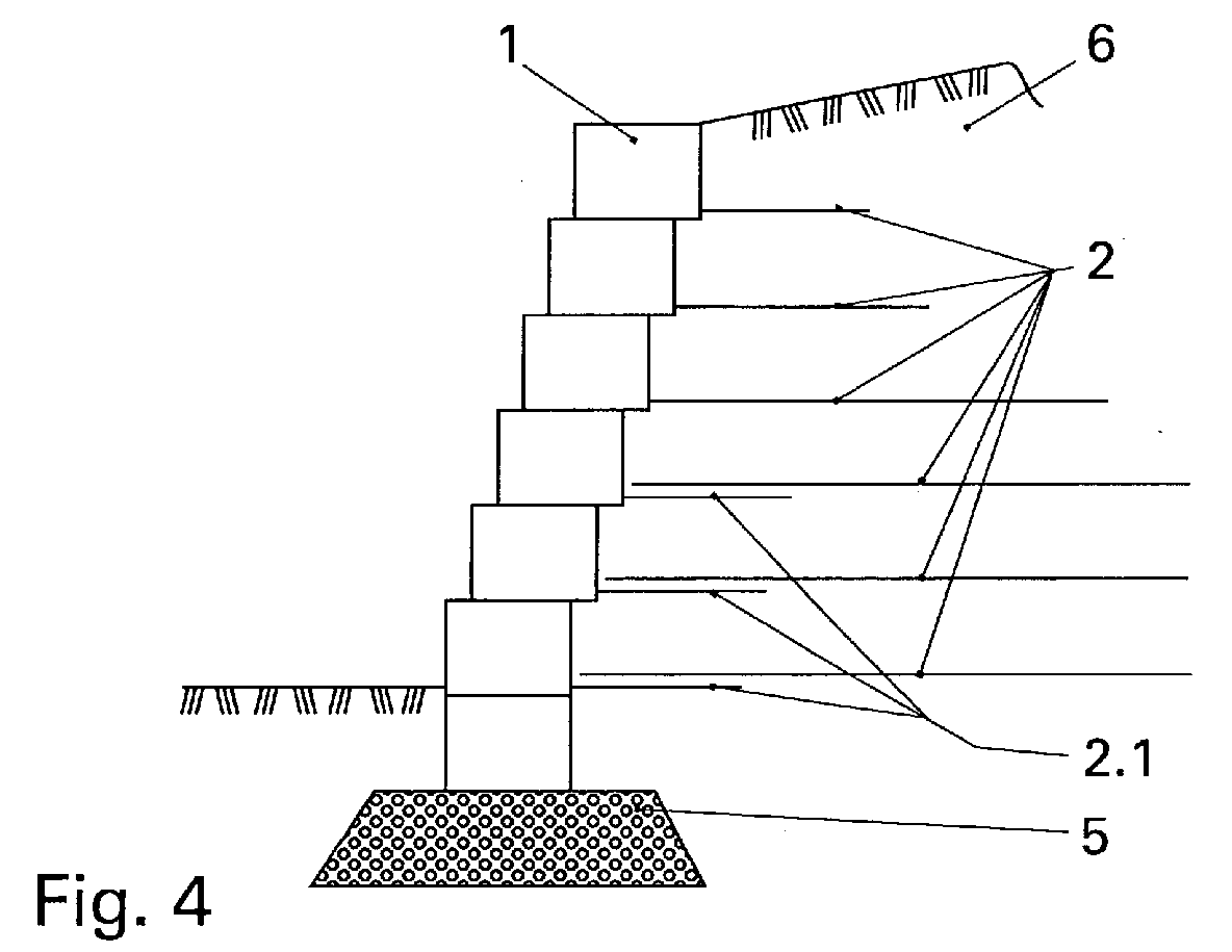
- Figure 4 shows a retaining wall, which was built with prefabricated parts 1 according to the invention, in a sectional view.
- the finished parts 1 are stacked side by side and one above the other, the lower row of finished parts 1 being placed on a cleanliness layer 5. All finished parts 1 with air-side contact have anchoring.
- the finished parts 1 of the top three rows have a geogrid 2, the length of these geogrids 2 being different at different heights as a result of a static dimensioning.
- Three of the prefabricated parts 1 shown have a relatively short geogrid 2 on their rear side; these geogrids 2 are each connected to a further geogrid 2.1, which causes anchoring back into an earth body 6.
- the geogrids 2 of the prefabricated parts 1, which are connected to a further geogrid 2.1, are formed with a unit length.
- FIG. 5 shows a further embodiment of a prefabricated part 1 according to the invention; the core of this finished part 1 is made of a light material 4, which serves to reduce the weight.
- the core of this prefabricated part 1 formed from light material 4 is completely encased by a concrete wall reinforced with reinforcement 3.
- FIG. 6 shows the top view of a first special part 1.1.
- This first special part 1.1 is a basic body cut from two cuboids, which is used to produce support walls angled in the floor plan.
- a geogrid 2 is arranged on the back of each partial block that forms this first special part 1.1.
- FIG. 7 shows a second special part 1.2, which is also suitable for forming support walls angled in the plan, this second special part 1.2 having a prismatic shape, the plan of this prismatic body forming an isosceles triangle.
- FIG. 8 shows the view of a support wall formed from a large number of prefabricated parts 1, third special parts 1.3 being arranged on the lateral boundary of the support wall shown on the left, which also have a prismatic shape.
- the prisms shown here have a triangular view.
- the special elements 1.1, 1.2, 1.3 shown in FIGS. 6 to 8 can be produced with any angle, so that supporting walls with any course in the floor plan and with any edge and head configurations can be produced.
Landscapes
- Engineering & Computer Science (AREA)
- Environmental & Geological Engineering (AREA)
- Life Sciences & Earth Sciences (AREA)
- General Life Sciences & Earth Sciences (AREA)
- Mining & Mineral Resources (AREA)
- Paleontology (AREA)
- Civil Engineering (AREA)
- General Engineering & Computer Science (AREA)
- Structural Engineering (AREA)
- Retaining Walls (AREA)
- Physical Or Chemical Processes And Apparatus (AREA)
- Moulds, Cores, Or Mandrels (AREA)
Abstract
Description
- Figur 1
- eine isometrische Darstellung eines einzelnen erfindungsgemäßen Fertigteils,
- Figur 2
- eine zugehörige Seitenansicht,
- Figur 3
- eine Seitenansicht eines einzelnen erfindungsgemäßen Fertigteils in einer weiteren Ausführungsform,
- Figur 4
- einen Schnitt durch eine aus erfindungsgemäßen Fertigteilen hergestellte Stützwand,
- Figur 5
- einen Schnitt durch eine weitere Ausführungsform eines Erfindungsgemäßen Fertigteils,
- Figur 6
- eine Draufsicht eines ersten Sonderelementes,
- Figur 7
- eine Draufsicht eines zweiten Sonderelementes und
- Figur 8
- einen Ausschnitt einer Ansicht einer aus erfindungsgemäßen Fertigteilen errichteten Stützwand.
- 1
- Fertigteil
- 1.1
- erstes Sonderteil
- 1.2
- zweites Sonderteil
- 1.3
- drittes Sonderteil
- 2
- Geogitter
- 2.1
- weiteres Geogitter
- 3
- Bewehrung
- 4
- Leichtstoff
- 5
- Sauberkeitsschicht
- 6
- Erdkörper
Claims (16)
- Stapelbares Fertigteil (1) aus Beton, insbesondere zur Herstellung von Stützwänden aus einzelnen Elementen, dadurch gekennzeichnet, dass das Fertigteil (1) mit einem Geogitter (2) verbindbar ist und dass das Geogitter (2) in einem Erdkörper (6) verankerter ist.
- Stapelbares Fertigteil (1) aus Beton, insbesondere zur Herstellung von Stützwänden aus einzelnen Elementen, dadurch gekennzeichnet, dass das Fertigteil (1) mit einem Geogitter (2) verbunden ist, dass das Geogitter (2) mit einem weiteren Geogitter (2.1) verbindbar ist und dass das weitere Geogitter (2.1) in einem Erdkörper (6) verankerbar ist.
- Fertigteil (1) nach Anspruch 1 oder 2, dadurch gekennzeichnet, dass Geogitter (2) verschiedener Fertigteile (1) mit einander koppelbar sind.
- Fertigteil (1) nach einem der vorhergehenden Ansprüche, dadurch gekennzeichnet, dass in dem Fertigteil eine Bewehrung (3) angeordnet ist.
- Fertigteil (1) nach Anspruch 4, dadurch gekennzeichnet, dass die Bewehrung (3) aus Baustahl besteht.
- Fertigteil (1) nach einem der vorhergehenden Ansprüche, dadurch gekennzeichnet, dass das Fertigteil (1) eine quaderförmige Form oder eine zumindest etwa quaderförmige Grundform mit mindestens einer Ausnehmung aufweist.
- Fertigteil (1) nach einem der vorhergehenden Ansprüche, dadurch gekennzeichnet, dass zur Gewichtsreduzierung in dem Fertigteil (1) ein Körper aus Leichtstoff (4) angeordnet ist oder dass im Kern des Fertigteiles (1) ein Hohlraum angeordnet ist.
- Fertigteil (1) nach Anspruch 7, dadurch gekennzeichnet, dass der Körper aus Leichtstoff (4) in dem Fertigteil (1) bis zu mindestens einer Seite des Fertigteiles (1) reicht und entfernbar ist.
- Fertigteil (1) nach einem der vorhergehenden Ansprüche, dadurch gekennzeichnet, dass das Geogitter (2) in das Fertigteil (1) einbetoniert ist.
- Fertigteil (1) nach einem der vorhergehenden Ansprüche, dadurch gekennzeichnet, dass das Geogitter (2) aus Kunststoff besteht.
- Fertigteil (1) nach einem der vorhergehenden Ansprüche, dadurch gekennzeichnet, dass an dem Fertigteil (1) Montageösen angeordnet sind.
- Fertigteil (1) nach einem der vorhergehenden Ansprüche, dadurch gekennzeichnet, dass unterhalb einer ersten Lage von Fertigteilen (1) ein Bodenaustausch oder eine Sauberkeitsschicht (5) angeordnet ist.
- Fertigteil (1) nach einem der Ansprüche 6 bis 12, dadurch gekennzeichnet, dass in Ausnehmungen des Fertigteiles (1) oder auf horizontalen Versätzen zu anderen Fertigteilen und/oder Stützwandelementen Erde und/oder Begrünungen angeordnet sind.
- Fertigteil (1) nach einem der Ansprüche 1 bis 5, dadurch gekennzeichnet, dass das Fertigteil (1) eine prismatische Grundform mit einem vieleckigen Grundriss aufweist und ein erstes Sonderteil (1.2) bildet.
- Fertigteil (1) nach einem der Ansprüche 1 bis 5, dadurch gekennzeichnet, dass das Fertigteil (1) eine prismatische Grundform mit einer dreieckigen Ansichtsfläche aufweist und ein drittes Sonderteil (1.3) bildet.
- Fertigteil (1) nach einem der Ansprüche 1 bis 5, dadurch gekennzeichnet, dass das Fertigteil (1) eine prismatische Grundform mit einem dreieckigen Grundriss aufweist und ein zweites Sonderteil (1.2) bildet.
Applications Claiming Priority (2)
| Application Number | Priority Date | Filing Date | Title |
|---|---|---|---|
| DE20215715U DE20215715U1 (de) | 2002-10-12 | 2002-10-12 | Fertigteil aus Beton für Stützwände mit Geogitterrückverhängung |
| DE20215715U | 2002-10-12 |
Publications (3)
| Publication Number | Publication Date |
|---|---|
| EP1408161A2 true EP1408161A2 (de) | 2004-04-14 |
| EP1408161A3 EP1408161A3 (de) | 2005-12-28 |
| EP1408161B1 EP1408161B1 (de) | 2010-12-15 |
Family
ID=7975924
Family Applications (1)
| Application Number | Title | Priority Date | Filing Date |
|---|---|---|---|
| EP03022793A Expired - Lifetime EP1408161B1 (de) | 2002-10-12 | 2003-10-11 | Fertigteil aus Beton für Stützwände mit Geogitterrückverhängung |
Country Status (3)
| Country | Link |
|---|---|
| EP (1) | EP1408161B1 (de) |
| AT (1) | ATE491846T1 (de) |
| DE (2) | DE20215715U1 (de) |
Cited By (2)
| Publication number | Priority date | Publication date | Assignee | Title |
|---|---|---|---|---|
| DE102008062820A1 (de) * | 2008-12-23 | 2010-07-22 | Andreas Herold | Böschungsbauwerk |
| US20220090343A1 (en) * | 2020-09-22 | 2022-03-24 | Big Block, Inc | Landscaping wall structure and form |
Families Citing this family (2)
| Publication number | Priority date | Publication date | Assignee | Title |
|---|---|---|---|---|
| FR2860811A1 (fr) * | 2003-10-13 | 2005-04-15 | Freyssinet Int Stup | Ouvrage en sol renforce et procede pour sa construction |
| DE202004001058U1 (de) * | 2004-01-24 | 2004-04-22 | Herold, Andreas, Dipl.-Ing. | Fertigteil aus Beton für Stützwände mit Geogitterrückverhängung |
Citations (1)
| Publication number | Priority date | Publication date | Assignee | Title |
|---|---|---|---|---|
| US20030118410A1 (en) | 2001-07-12 | 2003-06-26 | Keystone Retaining Wall Systems, Inc. | Grooved retaining wall block and system |
Family Cites Families (1)
| Publication number | Priority date | Publication date | Assignee | Title |
|---|---|---|---|---|
| US5807030A (en) * | 1993-03-31 | 1998-09-15 | The Reinforced Earth Company | Stabilizing elements for mechanically stabilized earthen structure |
-
2002
- 2002-10-12 DE DE20215715U patent/DE20215715U1/de not_active Expired - Lifetime
-
2003
- 2003-10-11 EP EP03022793A patent/EP1408161B1/de not_active Expired - Lifetime
- 2003-10-11 DE DE50313318T patent/DE50313318D1/de not_active Expired - Lifetime
- 2003-10-11 AT AT03022793T patent/ATE491846T1/de active
Patent Citations (1)
| Publication number | Priority date | Publication date | Assignee | Title |
|---|---|---|---|---|
| US20030118410A1 (en) | 2001-07-12 | 2003-06-26 | Keystone Retaining Wall Systems, Inc. | Grooved retaining wall block and system |
Cited By (4)
| Publication number | Priority date | Publication date | Assignee | Title |
|---|---|---|---|---|
| DE102008062820A1 (de) * | 2008-12-23 | 2010-07-22 | Andreas Herold | Böschungsbauwerk |
| DE102008062820B4 (de) * | 2008-12-23 | 2014-02-27 | Andreas Herold | Böschungsbauwerk |
| US20220090343A1 (en) * | 2020-09-22 | 2022-03-24 | Big Block, Inc | Landscaping wall structure and form |
| US12188195B2 (en) * | 2020-09-22 | 2025-01-07 | Big Block, Inc | Anchored walled system |
Also Published As
| Publication number | Publication date |
|---|---|
| EP1408161B1 (de) | 2010-12-15 |
| DE50313318D1 (de) | 2011-01-27 |
| ATE491846T1 (de) | 2011-01-15 |
| DE20215715U1 (de) | 2003-02-27 |
| EP1408161A3 (de) | 2005-12-28 |
Similar Documents
| Publication | Publication Date | Title |
|---|---|---|
| EP0170113B1 (de) | Baustein | |
| AT391507B (de) | Baustein | |
| DE69017364T2 (de) | Vorgefertigtes armiertes betonstützwandsystem. | |
| DE69813809T2 (de) | Böschungsmauersystem | |
| EP0234175B1 (de) | Bausatz zur Erstellung von Mauerwerken | |
| DE1811932A1 (de) | Betonbalken,insbesondere fuer Raumgitter und Stuetzmauern | |
| DE102004024802A1 (de) | Stützmauer und Formstein aus Beton zur Herstellung einer Stützmauer | |
| EP1408161B1 (de) | Fertigteil aus Beton für Stützwände mit Geogitterrückverhängung | |
| DE4131423A1 (de) | Bausatz aus beton-formsteinen sowie eine hieraus erstellte schwergewichts-stuetzmauer | |
| EP0016727B1 (de) | Bausatz aus Verbundsteinen, insbesondere für die Hangsicherung und Flussbettverbauung | |
| WO1990012927A1 (de) | Mauer | |
| EP1557498B1 (de) | Fertigteil aus Beton für Stützwände mit Geogitterrückverhängung | |
| DE102007036965B4 (de) | Bauwerk zur Aufbewahrung von Urnen | |
| DE3303144A1 (de) | Bepflanzbarer werkstein und bepflanzbare wand | |
| DE2937478A1 (de) | Bauteilsatz und bauelement zur herstellung von bauwerken sowie damit gebildete mauer und verwendung zur mauerherstellung | |
| EP1097273B1 (de) | Mauer, insbesondere zur mörtellosen befestigung von böschungen, terrassen, abhängen oder dergleichen | |
| DE2826324A1 (de) | Stuetzwand, bestehend aus einem aus beton-fertigteilen zusammengesetzten raumgitter, dessen hohlraeume mit schuettgut verfuellt sind | |
| DE69002609T2 (de) | Einstückige Betonfestigteile für die Herstellung von Stützmauern. | |
| AT360574B (de) | Stuetz- und futtermauer | |
| DE102017000128A1 (de) | Gabionenwandmodul und Verfahren zur Herstellung einer Gabionenwand mit wenigstens einem Gabionenwandmodul | |
| EP2929100B1 (de) | Mauerstein für ein mauersystem | |
| DE2716250A1 (de) | Aus vorgefertigten teilen bestehendes wandartiges geruest zur herstellung einer boeschungssicherung, laermschutzwand o.dgl. | |
| DE3445099A1 (de) | Betonfertigteil | |
| DE3685881T2 (de) | Stuetzbauwerk und verfahren zum verwirklichen dieses stuetzbauwerks. | |
| AT256403B (de) | Prismatisches Verbund-Bauelement |
Legal Events
| Date | Code | Title | Description |
|---|---|---|---|
| PUAI | Public reference made under article 153(3) epc to a published international application that has entered the european phase |
Free format text: ORIGINAL CODE: 0009012 |
|
| AK | Designated contracting states |
Kind code of ref document: A2 Designated state(s): AT BE BG CH CY CZ DE DK EE ES FI FR GB GR HU IE IT LI LU MC NL PT RO SE SI SK TR |
|
| AX | Request for extension of the european patent |
Extension state: AL LT LV MK |
|
| PUAL | Search report despatched |
Free format text: ORIGINAL CODE: 0009013 |
|
| AK | Designated contracting states |
Kind code of ref document: A3 Designated state(s): AT BE BG CH CY CZ DE DK EE ES FI FR GB GR HU IE IT LI LU MC NL PT RO SE SI SK TR |
|
| AX | Request for extension of the european patent |
Extension state: AL LT LV MK |
|
| 17P | Request for examination filed |
Effective date: 20060209 |
|
| AKX | Designation fees paid |
Designated state(s): AT BE BG CH CY CZ DE DK EE ES FI FR GB GR HU IE IT LI LU MC NL PT RO SE SI SK TR |
|
| RAP1 | Party data changed (applicant data changed or rights of an application transferred) |
Owner name: HEROLD, ANDREAS |
|
| RIN1 | Information on inventor provided before grant (corrected) |
Inventor name: HEROLD, ANDREAS |
|
| GRAP | Despatch of communication of intention to grant a patent |
Free format text: ORIGINAL CODE: EPIDOSNIGR1 |
|
| GRAS | Grant fee paid |
Free format text: ORIGINAL CODE: EPIDOSNIGR3 |
|
| GRAA | (expected) grant |
Free format text: ORIGINAL CODE: 0009210 |
|
| AK | Designated contracting states |
Kind code of ref document: B1 Designated state(s): AT BE BG CH CY CZ DE DK EE ES FI FR GB GR HU IE IT LI LU MC NL PT RO SE SI SK TR |
|
| REG | Reference to a national code |
Ref country code: GB Ref legal event code: FG4D Free format text: NOT ENGLISH Ref country code: CH Ref legal event code: EP |
|
| REG | Reference to a national code |
Ref country code: IE Ref legal event code: FG4D |
|
| REF | Corresponds to: |
Ref document number: 50313318 Country of ref document: DE Date of ref document: 20110127 Kind code of ref document: P |
|
| REG | Reference to a national code |
Ref country code: NL Ref legal event code: T3 |
|
| PG25 | Lapsed in a contracting state [announced via postgrant information from national office to epo] |
Ref country code: FI Free format text: LAPSE BECAUSE OF FAILURE TO SUBMIT A TRANSLATION OF THE DESCRIPTION OR TO PAY THE FEE WITHIN THE PRESCRIBED TIME-LIMIT Effective date: 20101215 Ref country code: SE Free format text: LAPSE BECAUSE OF FAILURE TO SUBMIT A TRANSLATION OF THE DESCRIPTION OR TO PAY THE FEE WITHIN THE PRESCRIBED TIME-LIMIT Effective date: 20101215 Ref country code: SI Free format text: LAPSE BECAUSE OF FAILURE TO SUBMIT A TRANSLATION OF THE DESCRIPTION OR TO PAY THE FEE WITHIN THE PRESCRIBED TIME-LIMIT Effective date: 20101215 Ref country code: CY Free format text: LAPSE BECAUSE OF FAILURE TO SUBMIT A TRANSLATION OF THE DESCRIPTION OR TO PAY THE FEE WITHIN THE PRESCRIBED TIME-LIMIT Effective date: 20101215 Ref country code: BG Free format text: LAPSE BECAUSE OF FAILURE TO SUBMIT A TRANSLATION OF THE DESCRIPTION OR TO PAY THE FEE WITHIN THE PRESCRIBED TIME-LIMIT Effective date: 20110315 |
|
| REG | Reference to a national code |
Ref country code: IE Ref legal event code: FD4D |
|
| PG25 | Lapsed in a contracting state [announced via postgrant information from national office to epo] |
Ref country code: CZ Free format text: LAPSE BECAUSE OF FAILURE TO SUBMIT A TRANSLATION OF THE DESCRIPTION OR TO PAY THE FEE WITHIN THE PRESCRIBED TIME-LIMIT Effective date: 20101215 Ref country code: EE Free format text: LAPSE BECAUSE OF FAILURE TO SUBMIT A TRANSLATION OF THE DESCRIPTION OR TO PAY THE FEE WITHIN THE PRESCRIBED TIME-LIMIT Effective date: 20101215 Ref country code: ES Free format text: LAPSE BECAUSE OF FAILURE TO SUBMIT A TRANSLATION OF THE DESCRIPTION OR TO PAY THE FEE WITHIN THE PRESCRIBED TIME-LIMIT Effective date: 20110326 Ref country code: GR Free format text: LAPSE BECAUSE OF FAILURE TO SUBMIT A TRANSLATION OF THE DESCRIPTION OR TO PAY THE FEE WITHIN THE PRESCRIBED TIME-LIMIT Effective date: 20110316 Ref country code: PT Free format text: LAPSE BECAUSE OF FAILURE TO SUBMIT A TRANSLATION OF THE DESCRIPTION OR TO PAY THE FEE WITHIN THE PRESCRIBED TIME-LIMIT Effective date: 20110415 Ref country code: IE Free format text: LAPSE BECAUSE OF FAILURE TO SUBMIT A TRANSLATION OF THE DESCRIPTION OR TO PAY THE FEE WITHIN THE PRESCRIBED TIME-LIMIT Effective date: 20101215 |
|
| PG25 | Lapsed in a contracting state [announced via postgrant information from national office to epo] |
Ref country code: SK Free format text: LAPSE BECAUSE OF FAILURE TO SUBMIT A TRANSLATION OF THE DESCRIPTION OR TO PAY THE FEE WITHIN THE PRESCRIBED TIME-LIMIT Effective date: 20101215 Ref country code: RO Free format text: LAPSE BECAUSE OF FAILURE TO SUBMIT A TRANSLATION OF THE DESCRIPTION OR TO PAY THE FEE WITHIN THE PRESCRIBED TIME-LIMIT Effective date: 20101215 |
|
| PLBE | No opposition filed within time limit |
Free format text: ORIGINAL CODE: 0009261 |
|
| STAA | Information on the status of an ep patent application or granted ep patent |
Free format text: STATUS: NO OPPOSITION FILED WITHIN TIME LIMIT |
|
| PG25 | Lapsed in a contracting state [announced via postgrant information from national office to epo] |
Ref country code: DK Free format text: LAPSE BECAUSE OF FAILURE TO SUBMIT A TRANSLATION OF THE DESCRIPTION OR TO PAY THE FEE WITHIN THE PRESCRIBED TIME-LIMIT Effective date: 20101215 |
|
| 26N | No opposition filed |
Effective date: 20110916 |
|
| PG25 | Lapsed in a contracting state [announced via postgrant information from national office to epo] |
Ref country code: IT Free format text: LAPSE BECAUSE OF FAILURE TO SUBMIT A TRANSLATION OF THE DESCRIPTION OR TO PAY THE FEE WITHIN THE PRESCRIBED TIME-LIMIT Effective date: 20101215 |
|
| REG | Reference to a national code |
Ref country code: DE Ref legal event code: R097 Ref document number: 50313318 Country of ref document: DE Effective date: 20110916 |
|
| BERE | Be: lapsed |
Owner name: HEROLD, ANDREAS Effective date: 20111031 |
|
| PG25 | Lapsed in a contracting state [announced via postgrant information from national office to epo] |
Ref country code: MC Free format text: LAPSE BECAUSE OF NON-PAYMENT OF DUE FEES Effective date: 20111031 |
|
| PG25 | Lapsed in a contracting state [announced via postgrant information from national office to epo] |
Ref country code: BE Free format text: LAPSE BECAUSE OF NON-PAYMENT OF DUE FEES Effective date: 20111031 |
|
| PG25 | Lapsed in a contracting state [announced via postgrant information from national office to epo] |
Ref country code: LU Free format text: LAPSE BECAUSE OF NON-PAYMENT OF DUE FEES Effective date: 20111011 |
|
| PG25 | Lapsed in a contracting state [announced via postgrant information from national office to epo] |
Ref country code: TR Free format text: LAPSE BECAUSE OF FAILURE TO SUBMIT A TRANSLATION OF THE DESCRIPTION OR TO PAY THE FEE WITHIN THE PRESCRIBED TIME-LIMIT Effective date: 20101215 |
|
| PG25 | Lapsed in a contracting state [announced via postgrant information from national office to epo] |
Ref country code: HU Free format text: LAPSE BECAUSE OF FAILURE TO SUBMIT A TRANSLATION OF THE DESCRIPTION OR TO PAY THE FEE WITHIN THE PRESCRIBED TIME-LIMIT Effective date: 20101215 |
|
| PGFP | Annual fee paid to national office [announced via postgrant information from national office to epo] |
Ref country code: FR Payment date: 20141021 Year of fee payment: 12 Ref country code: GB Payment date: 20141024 Year of fee payment: 12 Ref country code: CH Payment date: 20141024 Year of fee payment: 12 |
|
| PGFP | Annual fee paid to national office [announced via postgrant information from national office to epo] |
Ref country code: AT Payment date: 20141031 Year of fee payment: 12 Ref country code: NL Payment date: 20141030 Year of fee payment: 12 |
|
| REG | Reference to a national code |
Ref country code: CH Ref legal event code: PL |
|
| REG | Reference to a national code |
Ref country code: AT Ref legal event code: MM01 Ref document number: 491846 Country of ref document: AT Kind code of ref document: T Effective date: 20151011 |
|
| GBPC | Gb: european patent ceased through non-payment of renewal fee |
Effective date: 20151011 |
|
| REG | Reference to a national code |
Ref country code: NL Ref legal event code: MM Effective date: 20151101 |
|
| PG25 | Lapsed in a contracting state [announced via postgrant information from national office to epo] |
Ref country code: GB Free format text: LAPSE BECAUSE OF NON-PAYMENT OF DUE FEES Effective date: 20151011 Ref country code: CH Free format text: LAPSE BECAUSE OF NON-PAYMENT OF DUE FEES Effective date: 20151031 Ref country code: LI Free format text: LAPSE BECAUSE OF NON-PAYMENT OF DUE FEES Effective date: 20151031 |
|
| REG | Reference to a national code |
Ref country code: FR Ref legal event code: ST Effective date: 20160630 |
|
| PG25 | Lapsed in a contracting state [announced via postgrant information from national office to epo] |
Ref country code: AT Free format text: LAPSE BECAUSE OF NON-PAYMENT OF DUE FEES Effective date: 20151011 Ref country code: FR Free format text: LAPSE BECAUSE OF NON-PAYMENT OF DUE FEES Effective date: 20151102 Ref country code: NL Free format text: LAPSE BECAUSE OF NON-PAYMENT OF DUE FEES Effective date: 20151101 |
|
| PGFP | Annual fee paid to national office [announced via postgrant information from national office to epo] |
Ref country code: DE Payment date: 20201028 Year of fee payment: 18 |
|
| REG | Reference to a national code |
Ref country code: DE Ref legal event code: R119 Ref document number: 50313318 Country of ref document: DE |
|
| PG25 | Lapsed in a contracting state [announced via postgrant information from national office to epo] |
Ref country code: DE Free format text: LAPSE BECAUSE OF NON-PAYMENT OF DUE FEES Effective date: 20220503 |