EP1407846B1 - Werkzeugspanner - Google Patents
Werkzeugspanner Download PDFInfo
- Publication number
- EP1407846B1 EP1407846B1 EP20030021888 EP03021888A EP1407846B1 EP 1407846 B1 EP1407846 B1 EP 1407846B1 EP 20030021888 EP20030021888 EP 20030021888 EP 03021888 A EP03021888 A EP 03021888A EP 1407846 B1 EP1407846 B1 EP 1407846B1
- Authority
- EP
- European Patent Office
- Prior art keywords
- tool
- clamping device
- clamping
- offsetting
- tool clamping
- Prior art date
- Legal status (The legal status is an assumption and is not a legal conclusion. Google has not performed a legal analysis and makes no representation as to the accuracy of the status listed.)
- Expired - Lifetime
Links
Images

Classifications
-
- B—PERFORMING OPERATIONS; TRANSPORTING
- B23—MACHINE TOOLS; METAL-WORKING NOT OTHERWISE PROVIDED FOR
- B23Q—DETAILS, COMPONENTS, OR ACCESSORIES FOR MACHINE TOOLS, e.g. ARRANGEMENTS FOR COPYING OR CONTROLLING; MACHINE TOOLS IN GENERAL CHARACTERISED BY THE CONSTRUCTION OF PARTICULAR DETAILS OR COMPONENTS; COMBINATIONS OR ASSOCIATIONS OF METAL-WORKING MACHINES, NOT DIRECTED TO A PARTICULAR RESULT
- B23Q11/00—Accessories fitted to machine tools for keeping tools or parts of the machine in good working condition or for cooling work; Safety devices specially combined with or arranged in, or specially adapted for use in connection with, machine tools
- B23Q11/0032—Arrangements for preventing or isolating vibrations in parts of the machine
- B23Q11/0035—Arrangements for preventing or isolating vibrations in parts of the machine by adding or adjusting a mass, e.g. counterweights
-
- B—PERFORMING OPERATIONS; TRANSPORTING
- B23—MACHINE TOOLS; METAL-WORKING NOT OTHERWISE PROVIDED FOR
- B23B—TURNING; BORING
- B23B31/00—Chucks; Expansion mandrels; Adaptations thereof for remote control
- B23B31/02—Chucks
- B23B31/24—Chucks characterised by features relating primarily to remote control of the gripping means
- B23B31/26—Chucks characterised by features relating primarily to remote control of the gripping means using mechanical transmission through the working-spindle
- B23B31/261—Chucks characterised by features relating primarily to remote control of the gripping means using mechanical transmission through the working-spindle clamping the end of the toolholder shank
-
- F—MECHANICAL ENGINEERING; LIGHTING; HEATING; WEAPONS; BLASTING
- F16—ENGINEERING ELEMENTS AND UNITS; GENERAL MEASURES FOR PRODUCING AND MAINTAINING EFFECTIVE FUNCTIONING OF MACHINES OR INSTALLATIONS; THERMAL INSULATION IN GENERAL
- F16F—SPRINGS; SHOCK-ABSORBERS; MEANS FOR DAMPING VIBRATION
- F16F15/00—Suppression of vibrations in systems; Means or arrangements for avoiding or reducing out-of-balance forces, e.g. due to motion
- F16F15/32—Correcting- or balancing-weights or equivalent means for balancing rotating bodies, e.g. vehicle wheels
- F16F15/36—Correcting- or balancing-weights or equivalent means for balancing rotating bodies, e.g. vehicle wheels operating automatically, i.e. where, for a given amount of imbalance, there is movement of masses until balance is achieved
- F16F15/363—Correcting- or balancing-weights or equivalent means for balancing rotating bodies, e.g. vehicle wheels operating automatically, i.e. where, for a given amount of imbalance, there is movement of masses until balance is achieved using rolling bodies, e.g. balls free to move in a circumferential direction
-
- G—PHYSICS
- G01—MEASURING; TESTING
- G01M—TESTING STATIC OR DYNAMIC BALANCE OF MACHINES OR STRUCTURES; TESTING OF STRUCTURES OR APPARATUS, NOT OTHERWISE PROVIDED FOR
- G01M1/00—Testing static or dynamic balance of machines or structures
- G01M1/30—Compensating imbalance
- G01M1/36—Compensating imbalance by adjusting position of masses built-in the body to be tested
-
- B—PERFORMING OPERATIONS; TRANSPORTING
- B23—MACHINE TOOLS; METAL-WORKING NOT OTHERWISE PROVIDED FOR
- B23B—TURNING; BORING
- B23B2250/00—Compensating adverse effects during turning, boring or drilling
- B23B2250/04—Balancing rotating components
-
- B—PERFORMING OPERATIONS; TRANSPORTING
- B23—MACHINE TOOLS; METAL-WORKING NOT OTHERWISE PROVIDED FOR
- B23B—TURNING; BORING
- B23B2250/00—Compensating adverse effects during turning, boring or drilling
- B23B2250/16—Damping of vibrations
Definitions
- the invention relates to a tool clamp for clamping a tool or tool holder in a work spindle of a machine tool according to the preamble of claim 1.
- Such a tool clamp is from the JP 06 126589 A known.
- imbalance compensation takes place by means of a compensation ring arranged on the drawbar and counterweights which can be screwed into threaded bores at the tip of a work spindle and into threaded bores of a nut arranged at the end of the work spindle.
- a setting of the imbalance compensation remains here even with changing imbalances obtained.
- the object of the invention is to provide a tool clamp with an imbalance compensation of the type mentioned, in which a compensation of variable imbalances is possible even without additional space.
- the balancing weights integrated in the tensioner elements automatically assume a position that is dependent on the respective unbalance to compensate for the imbalance. Due to the integrated design, a particularly compact design without additional space is possible. In addition, a complex balancing can be omitted with special balancing machines.
- the device for automatic unbalance compensation consists of a in the tensioner element to its central axis coaxial orbit arranged with several freely movable balancing masses. These are in Advantageous to balls that can move freely with little friction within the track.
- a device for automatic unbalance compensation is integrated in several Spanncrelementen a tool clamp.
- This can e.g. be installed in a clamping set, an investment or support disk and / or a pull rod of a HSK tool clamp.
- the automatic unbalance compensation can be used in a similar manner but also in an SK tool clamp or other clamping system used. So z-B. the device for unbalance compensation also be integrated into the clamp holder, the bearing or support disks, the gear parts and / or the piston of an SK tool clamp.
- a liquid is arranged in the orbit in addition to the Aus GmbHskörpem.
- the reaction rate of the system can be changed or adapted.
- the viscosity of the liquid is variable from the outside. This can e.g. by changing the temperature of a viscous liquid.
- the property of the liquid within the orbit and thus also the behavior of the compensation body can also be changed by applying a magnetic field, provided that the liquid contains magnetizable particles. As a result, the unbalance compensation can be adapted to the different requirements.
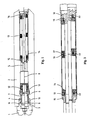
- FIG. 1 shows the front part of a device for clamping a hollow shaft tool 1 in a rotary-driven work spindle 2 of a machine tool.
- the clamping device In the upper half of the FIG. 1 the clamping device is shown in a release position and in the lower half in a clamping position.
- the hollow shaft tool 1 contains a conical hollow shaft 3 for engagement in a corresponding inner cone 4 at the front end of the hollow cylindrical work spindle 2.
- an axially movable clamping rod 5 is arranged, which carries at its tool-side front end a coaxial clamping sleeve 6 to the work spindle.
- a plurality of circumferentially equidistant clamping jaws 7 are arranged, which extend parallel to the central axis 8 of the work spindle.
- the clamping jaws 7 are by an axial movement of the clamping sleeve 6 by means of the clamping rod 5 between the in FIG. 1 Movable above shown release position and the clamping position shown below.
- the clamping jaws 7 have at their the hollow cone shaft 3 facing the front end of a radial thickening 9 with a conical clamping surface 10. This is at the bottom of the in FIG. 1 shown clamping position on an opposite conical inner surface of the cone hollow shaft 3 at. At their rear ends, the clamping claws 7 abut against a pressure ring 12, which is acted upon by a compression spring 13 in the direction of the clamping jaws 7.
- a compression spring system is arranged in the form of a plate spring package 14, which is supported on one side to a supported within the work spindle 2 contact washer 15 and on the other side to an annular shoulder 16 of the tension rod fifth supported.
- the disc spring assembly 14 consists of a front and rear disc spring assembly, which are separated by a support disc 17 arranged therebetween.
- the clamping rod 5 is pressed by an actuator, not shown, against the force of the disc spring assembly 14 forward until the voltage applied to the outside of the clamping sleeve 6 clamping jaws 7 in the in the upper half of FIG. 1 reach shown release position. In this position, the hollow shaft tool 1 is released for removal from the work spindle 2.
- FIG. 2 shows, in the contact plate 15, the support plate 17 and in the annular shoulder 16 of the tie rod 5 each integrated a device for automatic unbalance compensation, the structure in the following the example of in FIG. 3 illustrated enlarged support plate 17 is explained.
- the device for automatic unbalance compensation consists of a arranged in the support disc 17 orbit 18 with a plurality of freely movable balancing masses 19.
- the balancing weights 19 are designed as a rotational body in the form of balls.
- the concentric to the central axis 20 of the support disc 17 orbit 18 is disposed at the inner end of a machined from the one side of the support plate 17 annular groove 21.
- the width B of the orbit 18 is selected such that the balancing weights 19 can also move radially.
- the width B of the orbit 18 is thus greater by a predetermined amount than the diameter of the balls.
- the orbit 18 is rounded corresponding to the radius of the balls.
- the annular groove 21 is an example of rubber o.ä. existing circlip 22 used, which prevents falling out of the balls.
- the invention is not limited to the HSK clamping system described above. It can also be used in a similar way for SK clamping systems or other tool clamps.
Landscapes
- Engineering & Computer Science (AREA)
- Mechanical Engineering (AREA)
- Physics & Mathematics (AREA)
- General Engineering & Computer Science (AREA)
- Acoustics & Sound (AREA)
- Aviation & Aerospace Engineering (AREA)
- General Physics & Mathematics (AREA)
- Gripping On Spindles (AREA)
- Machine Tool Units (AREA)
Description
- Die Erfindung betrifft einen Werkzeugspanner zum Spannen eines Werkzeugs oder Werkzeughalters in einer Arbeitsspindel einer Werkzeugmaschine nach dem Oberbegriff des Anspruchs 1.
- Ein derartiger Werkzeugspanner ist aus der
JP 06 126589 A - Aufgabe der Erfindung ist es, einen Werkzeugspanner mit einem Unwuchtausgleich der eingangs genannten Art zu schaffen, bei dem auch ohne zusätzlichen Platzbedarf eine Ausgleich veränderlicher Unwuchten möglich ist.
- Diese Aufgabe wird durch einen Werkzeugspanner mit den Merkmalen des Anspruchs 1 gelöst. Zweckmäßige Ausgestaltungen und vorteilhafte Weiterbildungen der Erfindung sind in den Unteransprüchen angegeben.
- Bei dem erfindungsgemäßen Werkzeugspanner können Veränderungen von Art, Lage und Betrag einer Unwucht auch während des Betriebs ohne Eingriff von außen direkt ausgeglichen werden. Die in der Spannerelementen integrierten Ausgleichsmassen nehmen automatisch eine von der jeweiligen Unwucht abhängige Position zum Ausgleich der Unwucht ein. Durch die integrierte Ausführung ist eine besonders kompakte Bauweise ohne zusätzlichen Platzbedarf möglich. Außerdem kann auch ein aufwendiges Auswuchten mit speziellen Auswuchtmaschinen entfallen. Die Einrichtung zum automatischen Unwuchtausgleich besteht aus einer in dem Spannerelement zu dessen Mittelachse koaxial angeordneten Umlaufbahn mit mehreren darin frei beweglichen Ausgleichsmassen. Es handelt es sich hierbei in vorteilhafter Weise um Kugeln, die sich mit geringer Reibung frei innerhalb der Laufbahn bewegen können.
- Zweckmäßigerweise ist in mehreren Spanncrelementen eines Werkzeugspanners eine Einrichtung zum automatischen Unwuchtausgleich integriert. Diese kann z.B. in einem Spannsatz, einer Anlage- oder Stützscheibe und/oder einer Zugstange eines HSK-Werkzeugspanners eingebaut sein. Dadurch können auch größere Unwuchten an unterschiedlichen Stellen ausgeglichen werden. Der automatische Unwuchtausgleich kann in entsprechender Weise aber auch bei einem SK-Werkzeugspanner oder einem anderen Spannsystem zum Einsatz gelangen. So kann z-B. die Einrichtung zum Unwuchtausgleich auch in den Zangenhalter, die Anlage- oder Stützscheiben, die Getriebeteile und/oder den Kolben eines SK-Werkzeugspanners integriert sein.
- In einer weiteren zweckmäßigen Ausführung ist in der Umlaufbahn neben den Ausgleichskörpem auch eine Flüssigkeit angeordnet. Dadurch kann die Reaktionsgeschwindigkeit des Systems verändert bzw. angepaßt werden. In vorteilhafter Weise kann außerdem vorgesehen werden, daß die Viskosität der Flüssigkeit von außen veränderbar ist. Dies kann z.B. durch Veränderung der Temperatur einer viskosen Flüssigkeit erfolgen. Die Eigenschaft der Flüssigkeit innerhalb der Umlaufbahn und damit auch das Verhalten der Ausgleichskörper kann auch durch Anlegen eines Magnetfeldes verändert werden, sofern die Flüssigkeit magnetisierbare Partikel enthält. Dadurch kann der Unwuchtausgleich an die unterschiedlichen Anforderungen angepaßt werden.
- Weitere Besonderheiten und Vorzüge der Erfindung ergeben sich aus der folgenden Beschreibung eines bevorzugten Ausführungsbeispiels anhand der Zeichnung. Es zeigen:
- Figur 1
- den vorderen Teil eines Werkzeugspanners in einer Arbeitsspindel einer Werkzeugmaschine im Längschnitt;
- Figur 2
- eine vergrößerte Teilansicht des in
Figur 1 gezeigten Werkzeugspanners im Längsschnitt; - Figur 3
- ein Spannerelement des in
Figur 1 und 2 gezeigten Werkzeugspanners mit integrierter Einrichtung zum automatischen Unwuchtausgleich in einem Längs- und Querschnitt und - Figur 4
- eine schematische Darstellung zur Erläuterung der Funktionsweise des automatischen Unwuchtausgleichs.
- In
Figur 1 ist der vordere Teil einer Vorrichtung zum Spannen eines Hohlschaftwerkzeugs 1 in einer drehangetriebenen Arbeitsspindel 2 einer Werkzeugmaschine dargestellt. In der oberen Hälfte derFigur 1 ist die Spannvorrichtung in einer Lösestellung und in der unteren Hälfte in einer Spannstellung gezeigt. Das Hohlschaftwerkzeug 1 enthält einen Kegel-Hohlschaft 3 zum Eingriff in einen entsprechenden Innenkegel 4 am vorderen Ende der hohlzylindrischen Arbeitsspindel 2. - Innerhalb der Arbeitsspindel 2 ist eine axial bewegliche Spannstange 5 angeordnet, die an ihrem werkzeugseitigen vorderen Ende eine zur Arbeitsspindel 2 koaxiale Spannhülse 6 trägt. An der Außenseite der Spannhülse 6 sind mehrere in Umfangsrichtung gleichbeabstandete Spannklauen 7 angeordnet, die sich parallel zur Mittelachse 8 der Arbeitsspindel erstrecken. Die Spannklauen 7 sind durch eine Axialbewegung der Spannhülse 6 mittels der Spannstange 5 zwischen der in
Figur 1 oben gezeigten Lösestellung und der unten dargestellten Spannstellung bewegbar. Die Spannklauen 7 weisen an ihrem dem Kegel-Hohlschaft 3 zugewandten vorderen Ende eine radiale Verdickung 9 mit einer konischen Spannfläche 10 auf. Diese liegt bei der in der unteren Hälfte der inFigur 1 gezeigten Spannstellung an einer entgegengesetzt konischen Innenfläche des Kegel-Hohlschafts 3 an. An ihren hinteren Enden liegen die Spannklauen 7 an einem Druckring 12 an, der durch eine Druckfeder 13 in Richtung der Spannklauen 7 beaufschlagt wird. - Um die Spannstange 5 ist ein Druckfedersystem in Form eines Tellerfederpakets 14 angeordnet, das sich auf der einen Seite an einer innerhalb der Arbeitsspindel 2 abgestützen Anlagescheibe 15 und auf der anderen Seite an einem Ringabsatz 16 der Spannstange 5 abstützt. Das Tellerfederpaket 14 besteht aus einer vorderen und hinteren Tellerfederanordnung, die durch eine dazwischen angeordnete Stützscheibe 17 voneinander getrennt sind. Durch das Tellerfederpaket 14 wird die Spannstange 5 und die an ihrem vorderen Ende befestigte Spannhülse 6 in die in der unteren Hälfte der
Figur 1 gezeigte zurückgezogene Spannstellung gedrückt. Zum Lösen des Werkzeugspanners wird die Spannstange 5 durch eine nicht dargestellte Betätigungseinrichtung entgegen der Kraft des Tellerfederpakets 14 nach vorne gedrückt, bis die an der Außenseite der Spannhülse 6 anliegenden Spannklauen 7 in die in der oberen Hälfte vonFigur 1 dargestellte Lösestellung gelangen. In dieser Stellung wird das Hohlschaftwerkzeug 1 zur Entnahme aus der Arbeitsspindel 2 freigegeben. - Wie besonders aus
Figur 2 hervorgeht, ist in der Anlagescheibe 15, der Stützscheibe 17 und in dem Ringabsatz 16 der Spannstange 5 jeweils eine Einrichtung zum automatischen Unwuchtausgleich integriert, deren Aufbau im folgenden am Beispiel der inFigur 3 vergrößert dargestellten Stützscheibe 17 erläutert wird. Die Einrichtung zum automatischen Unwuchtausgleich besteht aus einer in innerhalb der Stützscheibe 17 angeordneten Umlaufbahn 18 mit mehreren darin frei beweglichen Ausgleichsmassen 19. Bei der gezeigten Ausführung sind die Ausgleichsmassen 19 als Rotationskörper in Form von Kugeln ausgeführt. Die zur Mittelachse 20 der Stützscheibe 17 konzentrische Umlaufbahn 18 ist am inneren Ende einer von der einen Seite der Stützscheibe 17 eingearbeiteten Ringnut 21 angeordnet. Die Breite B der Umlaufbahn 18 ist derart gewählt, daß sich die Ausgleichsmassen 19 auch radial bewegen können. Die Breite B der Umlaufbahn 18 ist somit um einen vorgegeben Betrag größer als der Durchmesser der Kugeln. An ihrer radial äußeren Innenwand ist die Umlaufbahn 18 entsprechend dem Radius der Kugeln abgerundet. In die Ringnut 21 ist ein z.B. aus Gummi o.ä. bestehender Sicherungsring 22 eingesetzt, der ein Herausfallen der Kugeln verhindert. - Anhand von
Figur 4 wird im folgenden das Prinzip des automatischen Unwuchtausgleichs erläutert. Bei vorhandener Unwucht wirkt bei einer Drehung des Spannerelements (hier: Stützscheibe 17) auf die innerhalb der Umlaufbahn frei beweglichen Kugeln eine Zentrifugalkraft Fz ausgehend vom Massenmittelpunkt (Schwerpunkt) 23. Das Spannerelement kann jedoch nur die radialen Komponenten Fz,r (ausgehend von Drehpunkt 24) aufnehmen, so daß auf die Kugeln die Komponente in Umfangsrichtung Fz,U wirkt. Infolge Fz,U bewegt sich jede Kugel solange, bis der Massenmittelpunkt 23 mit dem Drehpunkt 24 zusammenfällt (d.h. Fz,U = 0). Die Kugeln ordnen sich also automatisch als Gegengewicht zur Unwucht an. - Die Erfindung ist nicht auf das vorstehend beschriebene HSK-Spannsystem beschränkt. Sie ist in entsprechender Weise auch für SK-Spannsysteme oder andere Werkzeugspanner einsetzbar.
Claims (10)
- Werkzeugspanner zum Spannen eines Werkzeugs (1) oder Werkzeughalters in einer Arbeitsspindel (2) einer Werkzeugmaschine mit mehreren zur Drehachse (8) der Arbeitsspindel (2) koaxialen und bei deren Drehung mitrotierenden Spannerelementen (15, 16, 17), wobei in mindestens einem der Spannerelemente (15, 16, 17) eine Einrichtung zum Unwuchtausgleich (18, 19) integriert ist, dadurch gekennzeichnet, dass die Einrichtung zum Unwuchtausgleich (18, 19) eine in dem Spannerelement (15, 16, 17) zu dessen Mittelachse (20) koaxial angeordnete Umlaufbahn (18) mit mehreren darin in Umtangsrichtung frei beweglichen Ausgleichsmassen (19) umfaßt.
- Werkzeugspanner nach Anspruch 1, dadurch gekennzeichnet, dass die Ausgleichsmassen (19) als Rotationskörper, insbesondere Kugeln, ausgebildet sind.
- Werkzeugspanner nach Anspruch 1 oder 2, dadurch gekennzeichnet, dass die Ausgleichsmassen (19) auch radial beweglich innerhalb der Umlaufbahn (18) angeordnet sind.
- Werkzeugspanner nach einem der Ansprüche 1 bis 3, dadurch gekennzeichnet, dass die Breite (B) der Umlaufbahn (18) größer als der Durchmesser der als Rotationskörper ausgeführten Ausgleichsmassen (19) ist.
- Werkzeugspanner nach einem der Ansprüche 1 bis 4, dadurch gekennzeichnet, dass die Umlaufbahn (18) an ihrer radial äußeren Innenwand abgerundet ist.
- Werkzeugspanner nach einem der Ansprüche 1 bis 5, dadurch gekennzeichnet, dass die Umlaufbahn (18) an dem inneren Ende einer von der einen Seite des Spannerelements (15, 16, 17) eingearbeiteten Ringnut (21) angeordnet ist.
- Werkzeugspanner nach einem der Ansprüche 1 bis 6, dadurch gekennzeichnet, dass die Rotationskörper (19) durch einen in das Spannerelement (15, 16, 17) einsetzbaren Sicherungsring (22) gegen Herausfallen gesichert sind.
- Werkzeugspanner nach einem der Ansprüche 1 bis 7, dadurch gekennzeichnet, dass in der Umlaufbahn (18) eine Flüssigkeit angeordnet ist.
- Werkzeugspanner nach Anspruch 8, dadurch gekennzeichnet, dass die Viskosität der Flüssigkeit von außen veränderbar ist.
- Werkzeugspanner nach einem der Ansprüche 1 bis 9, dadurch gekennzeichnet, dass in mehreren Spannerelementen (15, 16, 17) jeweils eine Einrichtung zum automatischen Unwuchtausgleich (18, 19) integriert ist.
Applications Claiming Priority (2)
| Application Number | Priority Date | Filing Date | Title |
|---|---|---|---|
| DE20215709U | 2002-10-12 | ||
| DE20215709U DE20215709U1 (de) | 2002-10-12 | 2002-10-12 | Werkzeugspanner |
Publications (2)
| Publication Number | Publication Date |
|---|---|
| EP1407846A1 EP1407846A1 (de) | 2004-04-14 |
| EP1407846B1 true EP1407846B1 (de) | 2009-11-04 |
Family
ID=31969825
Family Applications (1)
| Application Number | Title | Priority Date | Filing Date |
|---|---|---|---|
| EP20030021888 Expired - Lifetime EP1407846B1 (de) | 2002-10-12 | 2003-09-27 | Werkzeugspanner |
Country Status (3)
| Country | Link |
|---|---|
| EP (1) | EP1407846B1 (de) |
| DE (2) | DE20215709U1 (de) |
| ES (1) | ES2333855T3 (de) |
Families Citing this family (5)
| Publication number | Priority date | Publication date | Assignee | Title |
|---|---|---|---|---|
| EP1669147B1 (de) * | 2004-12-13 | 2009-03-25 | Schunk GmbH & Co. KG Spann- und Greiftechnik | Spanneinrichtung |
| DE102016006092A1 (de) * | 2016-05-20 | 2017-11-23 | Klingelnberg Ag | WERKZEUGSPlNDEL MlT WUCHTSYSTEM, GESAMTSYSTEM, DAS ElNE WERKZEUGSPlNDEL MlT WUCHTSYSTEM UMFASST UND VERFAHREN ZUM BETREIBEN EINER WERKZEUGSPINDEL MIT WUCHTSYSTEM |
| EP3461585B1 (de) | 2017-10-02 | 2022-03-23 | Sandvik Intellectual Property AB | Werkzeugkörper mit einer dämpfungsvorrichtung und bearbeitungswerkzeug mit solch einem werkzeugkörper |
| CN114749968B (zh) * | 2022-03-01 | 2023-06-06 | 深圳大学 | 刀具夹具 |
| CN115847156A (zh) * | 2022-10-20 | 2023-03-28 | 江苏秦贵智能科技有限公司 | 一种数控机床用刀具夹头 |
Family Cites Families (7)
| Publication number | Priority date | Publication date | Assignee | Title |
|---|---|---|---|---|
| JPS57501020A (de) * | 1980-07-21 | 1982-06-10 | ||
| DE4106504C1 (en) * | 1991-03-01 | 1992-04-09 | Berg & Co. Gmbh Spanntechnik, 4800 Bielefeld, De | Vehicle drawbar actuating mechanism - incorporates shaft and ring piston with tapered outer surface |
| JPH06126589A (ja) * | 1992-10-21 | 1994-05-10 | Hitachi Seiko Ltd | 工作機械の主軸とその回転バランス調整方法 |
| JPH06126588A (ja) * | 1992-10-21 | 1994-05-10 | Hitachi Seiko Ltd | 工作機械の回転バランス調整方法 |
| US20020056338A1 (en) * | 2000-07-03 | 2002-05-16 | Stefan Olausson | Cost effective and reliable automatic balancer for high speed applications |
| DE10100627B4 (de) * | 2001-01-09 | 2010-09-30 | Kaltenbach & Voigt Gmbh & Co. Kg | Medizinisches oder dentalmedizinisches Handinstrument mit einer Unwuchtausgleichsvorrichtung und Verfahren zum Auswuchten des Handinstruments |
| DE10101095A1 (de) * | 2001-01-12 | 2002-07-25 | Ortlieb Praez S Spannzeuge Gmb | Spanneinrichtung für Werkzeuge, Werkzeughalter oder dergleichen |
-
2002
- 2002-10-12 DE DE20215709U patent/DE20215709U1/de not_active Expired - Lifetime
-
2003
- 2003-09-27 DE DE50312084T patent/DE50312084D1/de not_active Expired - Lifetime
- 2003-09-27 EP EP20030021888 patent/EP1407846B1/de not_active Expired - Lifetime
- 2003-09-27 ES ES03021888T patent/ES2333855T3/es not_active Expired - Lifetime
Also Published As
| Publication number | Publication date |
|---|---|
| EP1407846A1 (de) | 2004-04-14 |
| DE20215709U1 (de) | 2004-02-26 |
| DE50312084D1 (de) | 2009-12-17 |
| ES2333855T3 (es) | 2010-03-02 |
Similar Documents
| Publication | Publication Date | Title |
|---|---|---|
| DE3211567C2 (de) | ||
| EP2014396B1 (de) | Fliehkraftunterstütztes Werkzeugspannsystem | |
| EP1693134B1 (de) | Gewindebohreraufnahme | |
| EP2024265B1 (de) | Klemmvorrichtung | |
| EP3362215B1 (de) | Spanneinrichtung | |
| EP2747922B1 (de) | Vorrichtung und verfahren zum spannen eines bauteils an einem rotierenden maschinenteil | |
| EP3315266A1 (de) | Gewichtsausgleicher | |
| EP2030707B1 (de) | Langdrehmaschine | |
| EP2879824B1 (de) | Auswucht- oder messadapter | |
| EP2906377B1 (de) | Auswucht- oder messadapter | |
| EP2844413B1 (de) | Auswuchtadapter | |
| DE69417951T2 (de) | Elektrische Hilfskraftlenkvorrichtung | |
| EP1407846A1 (de) | Werkzeugspanner | |
| EP3366398A1 (de) | Spanneinheit für ein spannfutter einer werkzeugmaschinenspindel | |
| DE19618610A1 (de) | Werkzeugspindel mit Spanneinrichtung | |
| DE2315810C2 (de) | Gewindebohrfutter | |
| DE20320084U1 (de) | Innenspanneinrichtung und damit ausgerüstetes Spannsystem | |
| EP1065304B1 (de) | Spielfreie und zentrierende Hülsenkupplung für die Spindel einer Textilmaschine | |
| DE3708380C2 (de) | Zentrierdorn für Kupplungsscheiben und Verfahren zur Messung des Seitenschlages | |
| DE3434699C2 (de) | Kraftangetriebene Handmaschine zum Bohren, Polieren, Schleifen u. dgl. mit einer Spannvorrichtung | |
| DE2038699A1 (de) | Vorrichtung zum Einstellen des axialen Spiels von Kugel-Spindelgetrieben | |
| DE10129207A1 (de) | Schälmaschine zur spanenden Bearbeitung | |
| DE3606039C2 (de) | ||
| DE102011122485B4 (de) | Drehherz | |
| DE4025745A1 (de) | Spannfutter mit werkstuecklagebestimmung |
Legal Events
| Date | Code | Title | Description |
|---|---|---|---|
| PUAI | Public reference made under article 153(3) epc to a published international application that has entered the european phase |
Free format text: ORIGINAL CODE: 0009012 |
|
| AK | Designated contracting states |
Kind code of ref document: A1 Designated state(s): AT BE BG CH CY CZ DE DK EE ES FI FR GB GR HU IE IT LI LU MC NL PT RO SE SI SK TR |
|
| AX | Request for extension of the european patent |
Extension state: AL LT LV MK |
|
| 17P | Request for examination filed |
Effective date: 20041014 |
|
| AKX | Designation fees paid |
Designated state(s): AT BE BG CH CY CZ DE DK EE ES FI FR GB GR HU IE IT LI LU MC NL PT RO SE SI SK TR |
|
| AXX | Extension fees paid |
Extension state: MK Payment date: 20041014 Extension state: LT Payment date: 20041014 Extension state: AL Payment date: 20041014 Extension state: LV Payment date: 20041014 |
|
| DAX | Request for extension of the european patent (deleted) | ||
| RBV | Designated contracting states (corrected) |
Designated state(s): CH DE ES FR IT LI |
|
| GRAP | Despatch of communication of intention to grant a patent |
Free format text: ORIGINAL CODE: EPIDOSNIGR1 |
|
| GRAS | Grant fee paid |
Free format text: ORIGINAL CODE: EPIDOSNIGR3 |
|
| GRAA | (expected) grant |
Free format text: ORIGINAL CODE: 0009210 |
|
| AK | Designated contracting states |
Kind code of ref document: B1 Designated state(s): CH DE ES FR IT LI |
|
| REG | Reference to a national code |
Ref country code: CH Ref legal event code: EP Ref country code: CH Ref legal event code: NV Representative=s name: LUCHS & PARTNER PATENTANWAELTE |
|
| REF | Corresponds to: |
Ref document number: 50312084 Country of ref document: DE Date of ref document: 20091217 Kind code of ref document: P |
|
| REG | Reference to a national code |
Ref country code: ES Ref legal event code: FG2A Ref document number: 2333855 Country of ref document: ES Kind code of ref document: T3 |
|
| PLBE | No opposition filed within time limit |
Free format text: ORIGINAL CODE: 0009261 |
|
| STAA | Information on the status of an ep patent application or granted ep patent |
Free format text: STATUS: NO OPPOSITION FILED WITHIN TIME LIMIT |
|
| 26N | No opposition filed |
Effective date: 20100805 |
|
| REG | Reference to a national code |
Ref country code: FR Ref legal event code: ST Effective date: 20110531 |
|
| PG25 | Lapsed in a contracting state [announced via postgrant information from national office to epo] |
Ref country code: FR Free format text: LAPSE BECAUSE OF NON-PAYMENT OF DUE FEES Effective date: 20100930 |
|
| PGFP | Annual fee paid to national office [announced via postgrant information from national office to epo] |
Ref country code: CH Payment date: 20110927 Year of fee payment: 9 |
|
| PGFP | Annual fee paid to national office [announced via postgrant information from national office to epo] |
Ref country code: ES Payment date: 20110810 Year of fee payment: 9 |
|
| PGFP | Annual fee paid to national office [announced via postgrant information from national office to epo] |
Ref country code: IT Payment date: 20110923 Year of fee payment: 9 |
|
| REG | Reference to a national code |
Ref country code: CH Ref legal event code: PL |
|
| PG25 | Lapsed in a contracting state [announced via postgrant information from national office to epo] |
Ref country code: LI Free format text: LAPSE BECAUSE OF NON-PAYMENT OF DUE FEES Effective date: 20120930 Ref country code: CH Free format text: LAPSE BECAUSE OF NON-PAYMENT OF DUE FEES Effective date: 20120930 |
|
| PG25 | Lapsed in a contracting state [announced via postgrant information from national office to epo] |
Ref country code: IT Free format text: LAPSE BECAUSE OF NON-PAYMENT OF DUE FEES Effective date: 20120927 |
|
| REG | Reference to a national code |
Ref country code: ES Ref legal event code: FD2A Effective date: 20131018 |
|
| PG25 | Lapsed in a contracting state [announced via postgrant information from national office to epo] |
Ref country code: ES Free format text: LAPSE BECAUSE OF NON-PAYMENT OF DUE FEES Effective date: 20120928 |
|
| PGFP | Annual fee paid to national office [announced via postgrant information from national office to epo] |
Ref country code: DE Payment date: 20191108 Year of fee payment: 17 |
|
| REG | Reference to a national code |
Ref country code: DE Ref legal event code: R119 Ref document number: 50312084 Country of ref document: DE |
|
| PG25 | Lapsed in a contracting state [announced via postgrant information from national office to epo] |
Ref country code: DE Free format text: LAPSE BECAUSE OF NON-PAYMENT OF DUE FEES Effective date: 20210401 |