EP1406013A2 - Verdichter mit variabler Verdrängung - Google Patents
Verdichter mit variabler Verdrängung Download PDFInfo
- Publication number
- EP1406013A2 EP1406013A2 EP03022246A EP03022246A EP1406013A2 EP 1406013 A2 EP1406013 A2 EP 1406013A2 EP 03022246 A EP03022246 A EP 03022246A EP 03022246 A EP03022246 A EP 03022246A EP 1406013 A2 EP1406013 A2 EP 1406013A2
- Authority
- EP
- European Patent Office
- Prior art keywords
- bearing
- swash plate
- drive shaft
- variable displacement
- type compressor
- Prior art date
- Legal status (The legal status is an assumption and is not a legal conclusion. Google has not performed a legal analysis and makes no representation as to the accuracy of the status listed.)
- Granted
Links
Images


Classifications
-
- F—MECHANICAL ENGINEERING; LIGHTING; HEATING; WEAPONS; BLASTING
- F04—POSITIVE - DISPLACEMENT MACHINES FOR LIQUIDS; PUMPS FOR LIQUIDS OR ELASTIC FLUIDS
- F04B—POSITIVE-DISPLACEMENT MACHINES FOR LIQUIDS; PUMPS
- F04B27/00—Multi-cylinder pumps specially adapted for elastic fluids and characterised by number or arrangement of cylinders
- F04B27/08—Multi-cylinder pumps specially adapted for elastic fluids and characterised by number or arrangement of cylinders having cylinders coaxial with, or parallel or inclined to, main shaft axis
- F04B27/10—Multi-cylinder pumps specially adapted for elastic fluids and characterised by number or arrangement of cylinders having cylinders coaxial with, or parallel or inclined to, main shaft axis having stationary cylinders
- F04B27/1036—Component parts, details, e.g. sealings, lubrication
- F04B27/1054—Actuating elements
- F04B27/1063—Actuating-element bearing means or driving-axis bearing means
Definitions
- the present invention relates to a variable displacement swash plate type compressor that is applied to a vehicle air conditioning system.
- a compressor is installed in a refrigerant circuit for use in a vehicle air conditioning system.
- the compressor compresses refrigerant gas therein.
- a typical variable displacement swash plate type compressor is disclosed for use in a vehicle air conditioning system.
- a housing of the compressor includes a front housing, a cylinder block and a rear housing.
- the rear end of the front housing is joined to the front end of the cylinder block.
- the rear end of the cylinder block is joined to front end of the rear housing through a valve mechanism that includes a suction valve plate, a valve hole plate, a discharge valve plate and a retainer plate.
- a plurality of cylinder bores extends through the cylinder block so as to be parallel with each other.
- the front housing and the cylinder block define a crank chamber therebetween.
- a suction chamber and a discharge chamber are defined in the rear housing.
- a single-head piton is accommodated in each cylinder bore for reciprocation.
- a compression chamber is defined in the corresponding cylinder bore between the corresponding piston and the valve mechanism.
- a first shaft hole extends through the front housing.
- a first bearing is installed in the first shaft hole.
- a second shaft hole extends through the cylinder block.
- a second bearing is installed in the second shaft hole. That is, the first bearing is located frontward than the second bearing.
- a drive shaft is supported by the first and second bearings for rotation. The front end of the drive shaft protrudes from the front housing and is connected to an external drive source such as a vehicle engine so as to be driven.
- a support spring is interposed between the rear end of the drive shaft and the valve mechanism through a third bearing in the second shaft hole.
- the rear end of the drive shaft is in contact with the front end of the third bearing.
- the rear end of the third bearing is in contact with the front end of the support spring.
- the rear end of the support spring is in contact with the front end of the valve mechanism. The support spring urges the drive shaft frontward.
- a lug plate is fixed to the drive shaft in the crank chamber so as to integrally rotate with the drive shaft.
- a thrust bearing is interposed between a front wall of the front housing and the lug plate in the crank chamber.
- a swash plate is supported by the drive shaft in the crank chamber for rotation.
- a hinge mechanism is interposed between the lug plate and the swash plate. Thereby, the swash plate is synchronously rotated with the drive shaft and is inclinable with respect to a rotary axis of the drive shaft.
- the pistons engage with the periphery of the swash plate.
- the piston is reciprocated in the corresponding cylinder bore in accordance with the rotation of the swash plate.
- a control mechanism is installed in the rear housing and communicates with the crank chamber, the suction chamber and the discharge chamber. The control mechanism controls the pressure in the crank chamber.
- the swash plate oscillates in accordance with the inclination angle of the swash plate and thus the piston is reciprocated in the corresponding cylinder bore. Therefore, refrigerant gas in the suction chamber is drawn into the compression chamber, and the refrigerant gas is compressed therein, and then the compressed refrigerant gas in the compression chamber is discharged into the discharge chamber.
- the control mechanism controls the pressure in the crank chamber, since the inclination angle of the swash plate is varied, an amount of the refrigerant gas discharged from the compression chamber to the discharge chamber is also varied.
- the first bearing and the second bearing receive radial force that is applied to the drive shaft respectively in the front housing and the cylinder block.
- the thrust bearing receives compressive reaction force of the refrigerant gas through the piston, the shoes, the swash plate and the lug plate in the front housing.
- the crank chamber and the second shaft hole are communicated via the second bearing, and the support spring is interposed between the rear end of the drive shaft and the valve mechanism. Therefore, the thrust bearing receives the pressure in the crank chamber and urging force of the support spring, which are applied to the drive shaft and the lug plate.
- a cylindrical regulating member is fitted around a rear end of a drive shaft so as to have a slight clearance between the cylindrical regulating member and a valve mechanism without the support spring in the shaft hole of the cylinder block between the rear end of the drive shaft and the valve mechanism.
- a thrust bearing does not require receiving the urging force of the support spring. Therefore, power loss is reduced.
- the present invention is directed to a variable displacement swash plate type compressor whose power loss is reduced.
- a variable displacement swash plate type compressor is used in connection with an external drive source.
- the compressor includes a housing, a first bearing, a drive shaft, a lug plate, a swash plate, a single-head piston, a control mechanism and urging means.
- a cylinder bore, a crank chamber, a suction chamber and a discharge chamber are defined.
- the first bearing is accommodated on a front side of the housing.
- the first bearing receives radial force and thrust force.
- the drive shaft is supported by the first bearing in the housing rotatably.
- the lug plate is fixed to the drive shaft in the crank chamber.
- the swash plate is supported by the drive shaft in the crank chamber rotatably.
- the single-head piston is accommodated in the cylinder bore reciprocably and is connected to the swash plate so as to reciprocate in accordance with the rotation of the swash plate.
- the control mechanism communicates with the crank chamber, the suction chamber and the discharge chamber for controlling pressure in the crank chamber.
- the urging means is placed between the first bearing and the lug plate and has urging force for reducing thrust force applied to the first thrust bearing.
- a variable displacement swash plate type compressor according to a first preferred embodiment of the present invention is applied to a vehicle air conditioning system.
- the compressor will now be described with reference to FIGs. 1 through 3.
- a left side of the drawing is a front side and a right side thereof is a rear side.
- the rear end of a cup-shaped front housing 2 is joined to the front end of a cylinder block 1.
- the rear end of the cylinder block 1 is joined to the front end of a rear housing 7 through a valve mechanism that includes a suction valve plate 3, a valve hole plate 4, a discharge valve plate 5 and a retainer plate 6.
- the cylinder block 1, the front housing 2 and the rear housing 7 form a compressor housing.
- a plurality of cylinder bores 1 a, a shaft hole 1b, a muffler chamber 1 c and an inlet 1 d are defined.
- a shaft hole 2a is formed in the front housing 2.
- the cylinder block 1 and the front housing 2 define a crank chamber 8 therein.
- a drive shaft 12 extends through the crank chamber 8 and is supported by a first bearing 10 at the shaft hole 2a and by a second bearing 11 at the shaft hole 1 b rotatably.
- a shaft seal device 9 seals a clearance between the drive shaft 12 and the front housing 2.
- a tapered roller bearing is adopted as the first bearing 10.
- a radial bearing is adopted as the second bearing 11.
- the first bearing 10 includes an inner race 10a, an outer race 10b, a plurality of rollers 10c and a cage, which is not shown in the drawings.
- the drive shaft 12 is press-fitted inside the inner race 10a so as to integrally rotate with the inner race 10a.
- the outer race 10b is press-fitted into the front housing 2.
- the plurality of rollers 10c is interposed between the inner race 10a and the outer race 10b.
- a rolling contact surface of the inner race 10a is formed on a cylindrical surface whose central axis is the same as a rotary axis of the drive shaft 12.
- a rolling contact surface of the outer race 10b is formed on a tapered surface whose central axis is the same as the rotary axis of the drive shaft 12.
- the rolling contact surface of the outer race 10b is formed in such a manner that diameter of the rolling contact surface of the outer race 10b on the front side of the first bearing 10 becomes smaller than that on the rear side of the first bearing 10.
- Each of the rollers 10c is formed in such a manner that diameter of each of the rollers 10c on the front side of the first bearing 10 becomes smaller than that on the rear side of the first bearing 10. That is, each of the rollers 10c has the shape of a circular truncated cone.
- a lug plate 14 is fixed to the drive shaft 12 in the crank chamber 8 so as to integrally rotate with the drive shaft 12.
- a thrust bearing 13 is placed between a front wall of the front housing 2 and the lug plate 14 in the crank chamber 8.
- the drive shaft 12 extends though a coned disc spring 20 which is placed between the inner race 10a and the lug plate 14.
- the coned disc spring 20 is served as an urging means. Urging force f0 of the coned disc spring 20 is applied to the lug plate 14 rearward.
- a pair of arms 15 protrudes from the rear surface of the lug plate 14 rearward, although only one of the arms 15 is shown in FIG. 1.
- a cylindrical guide hole 15a is formed through each arm 15.
- the drive shaft 12 extends through a swash plate 16 where a through hole 16a is formed.
- An inclination angle of the swash plate 16 is defined as an angle between a perpendicular plane to the rotary axis of the drive shaft 12 and the swash plate 16.
- a spring 17 is interposed between the swash plate 16 and the lug plate 14 for reducing the inclination angle of the swash plate 16.
- a return spring 26 is interposed between the swash plate 16 and a circular clip 25.
- a bearing 27 is placed at the rear end of the drive shaft 12 in the shaft hole 1 b of the cylinder block 1.
- a support spring 29 is interposed between the bearing 27 and the suction valve plate 3.
- a regulating member may be used in place of the bearing 27 and the support spring 29.
- a pair of guide pins 16b protrudes from the front end of the swash plate 16 respectively to the pair of arms 15, although only one of the guide pins 16b is shown in FIG. 1.
- a spherical guide portion 16c is formed on the distal end of each guide pin 16b so as to pivotally slide along the corresponding guide hole 15a.
- the guide holes 15a of the lug plate 15 and the guide portions 16c of the swash plate 16 constitute a hinge mechanism, through which the swash plate 16 is rotated synchronously with the drive shaft 12 and inclines relative to the drive shaft 12.
- a plurality of hollow single-head pistons 19 is engaged with the periphery of the swash plate 16.
- Each piston 19 has a pair of shoes 18, which is placed respectively at the front and rear sides of the swash plate 16. Each piston 19 is also accommodated in each cylinder bore 1 a. A compression chamber 30 is defined on the rear side of the piston 19 in the corresponding cylinder bore 1 a.
- a pulley 22 is fixed to the front end of the drive shaft 12, which protrudes from the front housing 2 frontward, by a bolt 23.
- the pulley 22 is supported by a ball bearing 24 on the front housing 2 rotatably.
- a belt is partially wound around the pulley 22 so as to connect with an engine EG, which is served as an external drive source.
- a suction chamber 7a is defined.
- the suction chamber 7a and the inlet 1 d of the cylinder block 1 are communicated via a suction passage, which is not shown in FIG. 1.
- the suction chamber 7a and the cylinder bores 1 a are communicated respectively via suction ports 31, which are formed through the retainer plate 6, the discharge valve plate 5 and the valve hole plate 4.
- the inlet 1 d is connected to an evaporator EV of a refrigerant circuit by a piping.
- the evaporator EV is connected to a condenser CO through an expansion valve V by a piping.
- a discharge chamber 7b is defined around the suction chamber 1 a.
- the discharge chamber 7b and the muffler chamber 1 c of the cylinder block 1 are communicated via a discharge passage 7d, which extends through the retainer plate 6, the discharge valve plate 5, the valve hole plate 4 and the suction valve plate 3.
- the muffler chamber 1 c is connected to the condenser CO of the refrigerant circuit by a piping.
- the discharge chamber 7b is connected to the cylinder bores 1 a respectively by discharge ports 32, which extends through the valve hole plate 4 and the suction valve plate 3.
- a control mechanism 34 which communicates with the crank chamber 8, the suction chamber 7a and the discharge chamber 7b so as to control the pressure in the crank chamber 8, is accommodated in the rear housing 7.
- the control mechanism 34 is capable of adjusting the pressure in the crank chamber 8, for example, by detecting the pressure in the suction chamber 7a. Thereby, an amount of refrigerant gas discharged from the compression chamber 30 to the discharge chamber 7b is varied in accordance with reciprocation of the piston 19 based on an inclination of the swash plate 16.
- the above structured compressor compresses carbon dioxide filled in the refrigerant circuit. Carbon dioxide is served as a refrigerant gas. Specifically, while the engine EG drives, since the pulley 22 is rotated through the belt, the drive shaft 12 is continuously driven. Thereby, the swash plate 16 is oscillated and the piston 19 is reciprocated in the corresponding cylinder bore 1a. That is, the piston 19 is reciprocated in accordance with the rotation of the swash plate 16. Thus, refrigerant gas of the evaporator EV in the refrigerant circuit is drawn into the suction chamber 7a through the inlet 1 d and the refrigerant gas in the suction chamber 7a is drawn into the compression chamber 30.
- the compressed refrigerant gas in the compression chamber 30 is discharged into the discharge chamber 7b.
- the refrigerant gas in the discharge chamber 7b is discharged into the condenser CO through the muffler chamber 1c.
- the first and second bearings 10 and 11 receive radial force which is applied to the drive shaft 12 respectively in the front housing 2 and the cylinder block 1. Also, compressive reaction force of the refrigerant gas is transmitted to the piston 19, the shoes 18, the swash plate 16 and the lug plate 14. Further, in the compressor the crank chamber 8 communicates with the shaft hole 1 b of the cylinder block 1 through the second bearing 11 and the support spring 29 is interposed between the rear end of the drive shaft 12 and the valve mechanism. Therefore, the pressure in the crank chamber 8 is applied to the drive shaft 12 and the lug plate 14. In addition, urging force of the support spring 29 is applied to the drive shaft 12 and the lug plate 14.
- the force applied to the drive shaft 12 frontward in accordance with the pressure in the crank chamber 8 is f1.
- the urging force of the support spring 29 is f2, and that the compressive reaction force is f3.
- the urging force f0 of the coned disc spring 20 is set so as to be larger than resultant force of the force f1 which is the maximum value and the urging force f2 of the support spring 29.
- the force f1 based on the pressure in the crank chamber 8 becomes the maximum value.
- the urging force f2 is a fixed value.
- the compressive reaction force f3 is an extremely small value.
- the urging force f0 of the coned disc spring 20 is set so as to be larger than resultant force of the maximum force f1, which is the maximum value, and the urging force f2 of the support spring 29, the drive shaft 12 and the lug plate 14 are urged rearward. For this reason, a slight clearance is produced between the lug plate 14, that is, the thrust bearing 13, and the thrust bearing 13 does not receive thrust force. Consequently, rolling frictional force of the thrust bearing 13 is not generated and power loss is reduced.
- the thrust force which is applied to the coned disc spring 20 is received by the first bearing 10 through the inner race 10a.
- the inner race 10a prevents the coned disc spring 20 from sliding over the drive shaft 12, power loss is reduced due to sliding frictional force.
- the first bearing 10 receives thrust force and radial force. Therefore, operation of the compressor is not interrupted.
- the tapered roller bearing is adopted as the first bearing 10, the number of parts is reduced.
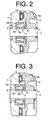
- the force f1 becomes a minimum value.
- the urging force f2 is a fixed value.
- the compressive reaction force f3 is maximum. Therefore, as shown in FIG. 3, the drive shaft 12 is urged frontward by resultant force of the force f1, the urging force f2 and the maximum compressive reaction force f3. Therefore, the lug plate 14 is also urged frontward.
- the urging force f0 of the coned disc spring 20 is defeated because the compressive reaction force f3 becomes maximum.
- the coned disc spring 20 is squeezed between the inner race 10a of the first bearing 10 and the lug plate 14.
- the drive shaft 12 and the lug plate 14 are urged frontward.
- the coned disc spring 20 is placed within a relatively short distance between the inner race 10a of the first bearing 10 and the lug plate 14 and operates the urging force f0 therein. Therefore, the length of the drive shaft 12 is shortened. Thereby, a relatively compact compressor is materialized.
- a variable displacement swash plate type compressor is also applied to a vehicle air conditioning system.
- a radial bearing 40 and a thrust bearing 50 whose rolling diameter is substantially equal to that of the radial bearing 40 are placed in place of the first bearing 10 of the first embodiment.
- the rolling diameter of the thrust bearing 50 is smaller than that of the thrust bearing 13.
- the radial bearing 40 is placed in the rear side of the shaft seal device 9.
- the thrust bearing 50 is placed in the front side of the coned disc spring 20.
- identical reference numerals to the first embodiment are applied to the same or corresponding members in the second embodiment and overlapped description is omitted.
- the thrust bearing 50 receives thrust force that is generated on the coned disc spring 20.
- the radial bearing 40 receives radial force caused by drive of the drive shaft 12.
Landscapes
- Engineering & Computer Science (AREA)
- Mechanical Engineering (AREA)
- General Engineering & Computer Science (AREA)
- Compressors, Vaccum Pumps And Other Relevant Systems (AREA)
- Support Of The Bearing (AREA)
- Compressor (AREA)
Applications Claiming Priority (2)
| Application Number | Priority Date | Filing Date | Title |
|---|---|---|---|
| JP2002292424 | 2002-10-04 | ||
| JP2002292424A JP2004124876A (ja) | 2002-10-04 | 2002-10-04 | 容量可変型斜板式圧縮機 |
Publications (3)
| Publication Number | Publication Date |
|---|---|
| EP1406013A2 true EP1406013A2 (de) | 2004-04-07 |
| EP1406013A3 EP1406013A3 (de) | 2006-11-29 |
| EP1406013B1 EP1406013B1 (de) | 2008-03-12 |
Family
ID=31987213
Family Applications (1)
| Application Number | Title | Priority Date | Filing Date |
|---|---|---|---|
| EP03022246A Expired - Lifetime EP1406013B1 (de) | 2002-10-04 | 2003-10-01 | Verdichter mit variabler Verdrängung |
Country Status (4)
| Country | Link |
|---|---|
| US (1) | US20040123731A1 (de) |
| EP (1) | EP1406013B1 (de) |
| JP (1) | JP2004124876A (de) |
| DE (1) | DE60319646D1 (de) |
Families Citing this family (2)
| Publication number | Priority date | Publication date | Assignee | Title |
|---|---|---|---|---|
| JP4608677B2 (ja) * | 2004-07-09 | 2011-01-12 | 株式会社 神崎高級工機製作所 | チャージリリーフ機構 |
| KR101378020B1 (ko) | 2008-01-18 | 2014-03-25 | 한라비스테온공조 주식회사 | 가변 용량형 사판식 압축기 |
Family Cites Families (6)
| Publication number | Priority date | Publication date | Assignee | Title |
|---|---|---|---|---|
| US5419685A (en) * | 1992-08-07 | 1995-05-30 | Kabushiki Kaisha Toyoda Jidoshokki Seisakusho | Reciprocating-piston-type refrigerant compressor with a rotary-type suction-valve mechanism |
| JP3094720B2 (ja) * | 1993-02-15 | 2000-10-03 | 株式会社豊田自動織機製作所 | 斜板式圧縮機 |
| JPH10281059A (ja) * | 1997-04-02 | 1998-10-20 | Sanden Corp | プーリー直結型容量可変型斜板式圧縮機 |
| JP2000170654A (ja) * | 1998-10-02 | 2000-06-20 | Toyota Autom Loom Works Ltd | 可変容量圧縮機 |
| JP2000303951A (ja) * | 1999-04-20 | 2000-10-31 | Toyota Autom Loom Works Ltd | ピストン式圧縮機 |
| JP2002013474A (ja) * | 2000-06-28 | 2002-01-18 | Toyota Industries Corp | 可変容量圧縮機 |
-
2002
- 2002-10-04 JP JP2002292424A patent/JP2004124876A/ja not_active Withdrawn
-
2003
- 2003-10-01 US US10/676,664 patent/US20040123731A1/en not_active Abandoned
- 2003-10-01 DE DE60319646T patent/DE60319646D1/de not_active Expired - Lifetime
- 2003-10-01 EP EP03022246A patent/EP1406013B1/de not_active Expired - Lifetime
Also Published As
| Publication number | Publication date |
|---|---|
| US20040123731A1 (en) | 2004-07-01 |
| EP1406013B1 (de) | 2008-03-12 |
| JP2004124876A (ja) | 2004-04-22 |
| EP1406013A3 (de) | 2006-11-29 |
| DE60319646D1 (de) | 2008-04-24 |
Similar Documents
| Publication | Publication Date | Title |
|---|---|---|
| JP3089901B2 (ja) | クラッチレス圧縮機における動力伝達構造 | |
| US5616008A (en) | Variable displacement compressor | |
| US6547533B2 (en) | Axial movement restriction means for swash plate compressor and compressor assembly method | |
| US6663355B2 (en) | Variable displacement compressor | |
| EP0855505A2 (de) | Kompressor mit variabler Fördermenge | |
| US6544004B2 (en) | Single-headed piston type compressor | |
| EP1074738A2 (de) | Taumelscheibenkompressor mit veränderlicher Förderleistung ohne Kupplung | |
| EP1406013B1 (de) | Verdichter mit variabler Verdrängung | |
| US6338613B1 (en) | Piston-type compressor | |
| US6446540B1 (en) | Bearing for swash plate compressor | |
| EP0952341A2 (de) | Kolbenführung für einen Taumelscheibenkompressor | |
| US20050233854A1 (en) | Variable speed compressor | |
| KR20090092229A (ko) | 경사판식 압축기 | |
| KR20220153923A (ko) | 스크롤 압축기 | |
| JP3856281B2 (ja) | 容量可変型斜板式圧縮機 | |
| KR20170060583A (ko) | 용량 가변형 경사판식 압축기 | |
| JP3182956B2 (ja) | クラッチレス揺動斜板式可変容量圧縮機 | |
| EP1164291A2 (de) | Taumelscheibenverdichter | |
| EP1067288A2 (de) | Lager für die Taumelscheibe eines Kompressors | |
| JP2000265948A (ja) | 可変容量型圧縮機 | |
| JP3324248B2 (ja) | クラッチレス片側ピストン式可変容量圧縮機 | |
| JP2006242355A (ja) | スラストニードル軸受 | |
| EP1288496A2 (de) | Verdichter mit variabler Verdrängung | |
| JPH109132A (ja) | 斜板型圧縮機 | |
| JPH10266954A (ja) | 可変容量圧縮機用制御弁及びその組付方法 |
Legal Events
| Date | Code | Title | Description |
|---|---|---|---|
| PUAI | Public reference made under article 153(3) epc to a published international application that has entered the european phase |
Free format text: ORIGINAL CODE: 0009012 |
|
| 17P | Request for examination filed |
Effective date: 20031001 |
|
| AK | Designated contracting states |
Kind code of ref document: A2 Designated state(s): AT BE BG CH CY CZ DE DK EE ES FI FR GB GR HU IE IT LI LU MC NL PT RO SE SI SK TR |
|
| AX | Request for extension of the european patent |
Extension state: AL LT LV MK |
|
| PUAL | Search report despatched |
Free format text: ORIGINAL CODE: 0009013 |
|
| AK | Designated contracting states |
Kind code of ref document: A3 Designated state(s): AT BE BG CH CY CZ DE DK EE ES FI FR GB GR HU IE IT LI LU MC NL PT RO SE SI SK TR |
|
| AX | Request for extension of the european patent |
Extension state: AL LT LV MK |
|
| AKX | Designation fees paid |
Designated state(s): DE FR IT |
|
| GRAP | Despatch of communication of intention to grant a patent |
Free format text: ORIGINAL CODE: EPIDOSNIGR1 |
|
| GRAS | Grant fee paid |
Free format text: ORIGINAL CODE: EPIDOSNIGR3 |
|
| GRAA | (expected) grant |
Free format text: ORIGINAL CODE: 0009210 |
|
| AK | Designated contracting states |
Kind code of ref document: B1 Designated state(s): DE FR IT |
|
| REF | Corresponds to: |
Ref document number: 60319646 Country of ref document: DE Date of ref document: 20080424 Kind code of ref document: P |
|
| EN | Fr: translation not filed | ||
| PLBE | No opposition filed within time limit |
Free format text: ORIGINAL CODE: 0009261 |
|
| STAA | Information on the status of an ep patent application or granted ep patent |
Free format text: STATUS: NO OPPOSITION FILED WITHIN TIME LIMIT |
|
| PG25 | Lapsed in a contracting state [announced via postgrant information from national office to epo] |
Ref country code: DE Free format text: LAPSE BECAUSE OF FAILURE TO SUBMIT A TRANSLATION OF THE DESCRIPTION OR TO PAY THE FEE WITHIN THE PRESCRIBED TIME-LIMIT Effective date: 20080613 |
|
| 26N | No opposition filed |
Effective date: 20081215 |
|
| PG25 | Lapsed in a contracting state [announced via postgrant information from national office to epo] |
Ref country code: FR Free format text: LAPSE BECAUSE OF FAILURE TO SUBMIT A TRANSLATION OF THE DESCRIPTION OR TO PAY THE FEE WITHIN THE PRESCRIBED TIME-LIMIT Effective date: 20090102 |
|
| PG25 | Lapsed in a contracting state [announced via postgrant information from national office to epo] |
Ref country code: IT Free format text: LAPSE BECAUSE OF FAILURE TO SUBMIT A TRANSLATION OF THE DESCRIPTION OR TO PAY THE FEE WITHIN THE PRESCRIBED TIME-LIMIT Effective date: 20080312 |