EP1405972B1 - Dispositif de verrouillage, battant semi-fixe d'une porte à deux battants avec un tel dispositif et procédé de montage - Google Patents
Dispositif de verrouillage, battant semi-fixe d'une porte à deux battants avec un tel dispositif et procédé de montage Download PDFInfo
- Publication number
- EP1405972B1 EP1405972B1 EP20030018932 EP03018932A EP1405972B1 EP 1405972 B1 EP1405972 B1 EP 1405972B1 EP 20030018932 EP20030018932 EP 20030018932 EP 03018932 A EP03018932 A EP 03018932A EP 1405972 B1 EP1405972 B1 EP 1405972B1
- Authority
- EP
- European Patent Office
- Prior art keywords
- latch
- operating device
- leaf
- slider
- door
- Prior art date
- Legal status (The legal status is an assumption and is not a legal conclusion. Google has not performed a legal analysis and makes no representation as to the accuracy of the status listed.)
- Expired - Lifetime
Links
Images


Classifications
-
- E—FIXED CONSTRUCTIONS
- E05—LOCKS; KEYS; WINDOW OR DOOR FITTINGS; SAFES
- E05C—BOLTS OR FASTENING DEVICES FOR WINGS, SPECIALLY FOR DOORS OR WINDOWS
- E05C7/00—Fastening devices specially adapted for two wings
- E05C7/04—Fastening devices specially adapted for two wings for wings which abut when closed
-
- E—FIXED CONSTRUCTIONS
- E05—LOCKS; KEYS; WINDOW OR DOOR FITTINGS; SAFES
- E05C—BOLTS OR FASTENING DEVICES FOR WINGS, SPECIALLY FOR DOORS OR WINDOWS
- E05C1/00—Fastening devices with bolts moving rectilinearly
- E05C1/08—Fastening devices with bolts moving rectilinearly with latching action
- E05C1/10—Fastening devices with bolts moving rectilinearly with latching action with operating handle or equivalent member rigid with the latch
-
- E—FIXED CONSTRUCTIONS
- E05—LOCKS; KEYS; WINDOW OR DOOR FITTINGS; SAFES
- E05C—BOLTS OR FASTENING DEVICES FOR WINGS, SPECIALLY FOR DOORS OR WINDOWS
- E05C7/00—Fastening devices specially adapted for two wings
- E05C7/04—Fastening devices specially adapted for two wings for wings which abut when closed
- E05C7/045—Sliding bolts mounted on or in the edge of a normally closed wing of a double-door or -window
Definitions
- the invention relates to a locking device, as shown in the WO 97/17519 is known. For further details, reference is expressly made to this document. Moreover, the invention relates to a passive leaf provided therewith. Finally, the invention relates to a mounting method for mounting such a locking device on the inactive leaf.
- the US 5,328,217 A discloses a locking device for the inactive leaf of a multi-leaf door in which an upper catch is urged spring-loaded in the locking position.
- a manually operable actuating device is provided, via which the catch can be pulled against its bias in the open position.
- the actuating device is formed at least in sections like a spring tongue, wherein a projection for engagement in one of the openings of the sliding plate is provided.
- a push rod is connected, which extends in the over the entire height of the door leaf extending hollow profile and transmits the movement of the actuator to the bolt.
- a further bolt is provided at the lower end of the door leaf.
- US 3,617,080 A a locking device for the inactive leaf of a two-leaf door according to the preamble of claim 1, wherein an upper catch is urged spring loaded in the locking position.
- an actuating device is equipped with two, for example, operable with the fingers sliders. The slides are connected in the interior of the hollow profile via a rope or optionally a rod with the upper catch and with a lower catch.
- the object of the invention is to provide a comparison with the known version simpler and much cheaper solution.
- a standing wing provided with the locking device according to the invention, a fire protection door provided therewith and a mounting method for the locking device are the subject matter of the dependent claims.
- the lock according to the invention is a significant simplification of today's known systems.
- a preferred embodiment can be dispensed with a determination in the open door state by a double suspension of a push rod or a locking bolt of the locking device. Ie. by translational movement of the slide of the locking bolt (in the following called Schnäpper) pulled into the door leaf and at the same time the spring tensioned in the push rod.
- Schnäpper translational movement of the slide of the locking bolt pulled into the door leaf and at the same time the spring tensioned in the push rod.
- the catch is in turn resiliently mounted, so that when closing the inactive leaf this is pressed over the inclined plane into the door leaf (Schnäpperfeder is thereby tensioned). If the inactive leaf reaches its closing position, the catch slips as a result of the spring force into a striking plate provided in the frame.
- the locking device is housed in a canister or in a central rung of the double-leaf door.
- the actual wing body of the passive leaf can be arbitrarily designed.
- Only the front side patch central rung is hollow for receiving the locking device and formed with corresponding frontal and upper side openings.
- a separate biasing device can be a different bias of the catch and actuator can be achieved.
- This is particularly advantageous if the catch is pressed regardless of the actuator by attacking the frame on the Schnäppersschräge in its Entriegelungslage so that the passive leaf - for example by means of a door closer - locked automatically when closing.
- the catch can snap back easily when closing the inactive leaf.
- the second spring or the like biasing means that the actuator is safely automatically brought back into the closed position after an operation from the unlocked position automatically.
- the catch is preferably connected to the actuating device via a freewheel or a one-way driver device.
- this could have a slot in which a pin engages, so that an initiated on the catch Eindgurterrorism of the latch takes place without entrainment of the actuator, with a movement of the actuator in the unlocked position but always entrains the catch.
- the locking device is divided into at least two modules for ease of assembly and for adaptation purposes.
- a Schnäpulsmodul comprises in addition to the catch - and possibly a Schnäppergephaseuse and possibly a Schnäpperfeder as Schnäppervorspann Rhein - a first connecting element which is connected to the catch - optionally via the aforementioned driving device - connected.
- the second module is formed by the actuating device, which has an actuating member, for example a manually movable slide, and a second connecting element.
- the second connection element may be formed integrally with the slider.
- the two modules are preferably detachably connectable to one another via a connection device.
- connection device is preferably designed in such a way that the two modules can be connected to one another even when the actuating device is already mounted on the inactive leaf. This allows a mounting method, according to which first the actuator is attached from the front side of the face of the inactive leaf, then the Schnäppermodul is inserted through the upper narrow side, so the top, the passive leaf and then the connecting element of the Schnäppermoduls means of the connecting device to the actuator of Actuator is connected.
- connection device preferably has a thread.
- the first connecting element for example formed by a latching rod
- the second connecting element connected to the actuating element.
- the actuating member is preferably housed in a recess of a guide or fastening member to be used for fastening and eventaell for guiding actuating movement of the actuating device in the end face of the passive leaf, such as a slider housing or slider guide device.
- the recessed arrangement of the run of the wing is not obstructed despite frontal arrangement.
- the locking device according to the invention is particularly suitable for fire doors (eg fire protection according to German DIN 4102), ie for doors which reliably prevent fire in a one-sided fire exposure over a certain period of time.
- fire doors eg fire protection according to German DIN 4102
- Such fire doors usually have to be equipped with a device for automatically closing the doors, for example spring strips or door closers, be equipped. Since the inactive leaf forms an abutment for the aerofoil and in case of fire large mechanical forces act on both wings, a secure hold of the inactive leaf is necessary.
- elaborate locking devices have been provided. With the locking device according to the invention, the requirements for fire doors with respect to the automatic closing and locking can be met with a significantly simpler design than before.
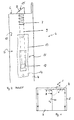
- Fig. 1 shows a two-leaf door 1 with a frame 2, a wing 3 and a passive leaf 4.
- a door closer (not shown) is housed with closing sequence controller, the two wings 3, 4 in the appropriate order automatically from a opened state in a closed state transferred.
- the frame in the upper Zargenholm at the bottom of a strike plate (not shown) with a receptacle for a locking bolt of a locking device 5 of the inactive leaf.
- the inactive leaf 4 is locked in the frame 2 by means of the locking device 5, which will be described below with reference to FIG Fig. 2 is explained in more detail.
- the door leaves of the two wings 3, 4 are designed as a door box made of sheet steel and provided with a conventional filling.
- the door 1 is designed in fire protection training and holds a einseifgen exposure to fire at least 30 minutes.
- Fig. 2 shows the detail X of Fig. 1 seen in the direction of the arrows II-II.
- Fig. 2 For example, the upper corner of the passive leaf 4 of the double-leaf door 1 directed towards the aerofoil is shown.
- the catch 8 is connected to a connecting rod 9, which is connected at its other end to an actuating device 11 arranged on the vertical end face 10.
- the actuator 11 has in the present example as an actuator on a slider 12.
- the slider 12 is seated here in a channel latch 13.
- the channel latch 13 forms an actuator attachment means and slider guide means disposed on or in the face 10. This is according to the embodiment Fig.
- a slide housing 14 designed in a U-shape, as a square tube or rectangular tube.
- the slide housing 14 is open toward the end, so that the slide 12 can be manually actuated.
- the front side 10 is the narrow side of the passive leaf 4 which points in the closed state of the door 1 to the aerofoil 3.
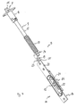
- a (further) embodiment of the locking device 5 is shown.
- the locking device 5 the catch 8 with an inclined plane 15, to be fixed to the inactive leaf 4 Schnäppergeophuse 16 for the catch 8, a (short) Schnäpperstange 17 as a connecting rod 9, a connecting rod spring 18, a connecting bracket 19, the actuator 11 with the slider 12 and the slider housing 14.
- both the catch 8 and the actuator are sprung.
- both the latch 8 and the actuating device 11 are provided with a biasing device for biasing in the closed position.
- the catch 8 is displaceable relative to the catch housing 16 and connected via the catch rod 17 with the connecting angle 19 and the slider 12.
- the catch 8 and the slider 12 are displaceable relative to each other, wherein the displaceability is limited by a stop, not shown. When pulling on the slider 12 this pulls back over the stop and the two connecting elements 17 and 19, the latch 8.
- the connecting rod spring 18 biases the catch 8 and the actuator 11 with the slider 12 in the mutual stop.
- the catch 8 can move back against the prestressing independently of the actuating device 11 into the catch housing 16 when the passive leaf 4 is slammed shut.
- the actuator attachment means and slider guide means is formed by a sheet metal 20 to be screwed onto the end face 10 provided with a recess 21.
- a slot 22 In the recess 21 is a slot 22 through which the slider 12 is connected to the connecting angle 19. The slider 12 is completely received in the recess 21 so that it does not protrude beyond the end face.
- the connecting angle 19 has a connecting flange 24, one of which is bent at right angles extending middle part 25 with slot 23 and a cranked end portion 26 which carries the slider 12.
- the connecting flange 24 is engaged with the free end of the catch rod 17.
- the slot 23 serves to guide the translational actuation movement of the connection angle 19 on the plate 20th
- Fig. 4 shows the arrangement with the Schnäpperfeder 7 and the connecting rod spring 18.
- the Schnäpperstange 17 and the connection angle 19 are connected by a detachable connection device 27 to each other.
- the connection device 27 here has a thread 30 at the free end of the catch rod 17 and a complementary threaded hole in the connection flange 24.
- the connection flange 24 is used at the same time as an abutment for the connecting rod spring 18, the other end is supported in a manner not shown fixed to the inactive leaf 4.
- the locking device 5 shown there consists of two modules. This is on the one hand by the Schnäppergeophuse 15 with latch 8 and the connected Schnäpperstange 19 formed Schnäppermodul 35 and on the other hand, the actuator 11 with the slider 12, the slide housing 14 and sheet 20 and the connection angle 19.
- the two modules 35, eleventh are connected by the thread 30 to each other.
- a preferred mounting location for the locking device 5 is shown.
- door 1 shown are the aerofoil 3 and the inactive leaf 4 with corresponding door leaf main bodies 29 constructed.
- a hollow profile 32 is fastened in the frontal area as a central rung 31.
- the stops and abutments are designed for the pedestrian wing.
- the hollow profile also carries door seals for sealing the middle door gap. The assembly is preferably carried out in this central rung 31, as in Fig. 6 is shown in more detail.
- the actuator 11 is first used with the sheet 20 frontally into the central rung 31 and secured by screws 33.
- the screws 33 engage on the henseite of the sheet 20 in the slot 23 for the purpose of leadership.
- From the top 34 from the Schnäppermodul 35 is then inserted and screwed over the thread 30. Thereafter, the Schnäppergepuruse 16 is attached to the upper side.
Claims (20)
- Dispositif de verrouillage (5) pour d'un battant semi-fixe (4) d'une porte (1) à plusieurs battants ayant une fonction d'autoverrouillage, dans laquelle un pêne (8) chargé par ressort, est poussé en position de verrouillage et une installation d'actionnement (11) à commande manuelle à partir de la face frontale (10), installée sur la face frontale (10) et pour tirer le pêne (8) contre sa précontrainte pour le mettre en position d'ouverture,
dispositif de verrouillage dont l'installation d'actionnement (11) est reliée au pêne (8) par une installation d'entraînement de façon que le pêne (8) puisse être enfoncé en position déverrouillée à partir de sa position verrouillée sans entraîner l'installation d'actionnement (11),
dispositif caractérisé en ce que
l'installation d'actionnement (11) comporte un coulisseau (12) coulissant manuellement, relié au pêne (8) par une tige de liaison (9),
le pêne (8) et le coulisseau (12) pouvant coulisser l'un par rapport à l'autre. - Dispositif selon la revendication 1,
caractérisé en ce que
le pêne (8) est un pêne haut (8). - Dispositif selon la revendication 1 ou 2,
caractérisé en ce que
le coulisseau (12) est installé sur ou dans une installation de guidage de coulissement (20, 14) prévue sur la face frontale (10). - Dispositif selon la revendication 3,
caractérisé en ce que
l'installation de guidage de coulissement est un boîtier de coulisseau (14). - Dispositif selon la revendication 4,
caractérisé en ce que
le boîtier de coulisseau (14) est formé par un verrou de chant (13) ou un profil creux (32) rapporté sur le corps de base du battant de porte (29) pour réaliser un battant semi-fixe (4). - Dispositif selon l'une des revendications 3 à 5,
caractérisé en ce que
l'installation de guidage de coulisseau, comporte une tôle (20) munie d'une fente (22) qui se fixe sur la face frontale du battant mobile pour assurer le guidage en coulissement. - Dispositif selon l'une des revendications précédentes,
caractérisé par
un ressort double (7, 18). - Dispositif selon la revendication 7,
caractérisé en ce qu'
à la fois le pêne (8) et l'installation d'actionnement (11) sont montés à ressort. - Dispositif selon l'une des revendications précédentes,
caractérisé en ce que
le pêne (8) est muni d'une installation de précontrainte (7) qui précontraint le pêne (8) dans sa position de verrouillage et l'installation d'actionnement (11) est munie d'une installation de précontrainte (18) qui assure la précontrainte de l'installation d'actionnement (11) dans sa position de fermeture. - Dispositif selon la revendication 9,
caractérisé en ce que
la force de précontrainte du dispositif de précontrainte de pêne (7) est inférieure à la force de précontrainte de l'installation de précontrainte de l'installation d'actionnement (18). - Dispositif selon la revendication 9 ou 10,
caractérisé en ce que
l'installation de précontrainte de pêne comporte un ressort de pêne (7) pour assurer la précontrainte du pêne (8), et
l'installation d'actionnement comporte une installation de précontrainte (18) avec un élément de ressort de liaison (18) qui précontraint un organe d'actionnement (12) de l'installation d'actionnement (11) et/ou un élément de liaison (17, 19) reliant le pêne (8) à l'organe d'actionnement (12) dans sa position de fermeture. - Dispositif selon l'une des revendications précédentes,
caractérisé par- un premier élément de liaison (17) relié au pêne (8), et- l'installation d'actionnement (11) comporte un second élément de liaison (19) relié à un organe d'actionnement (12) de l'installation d'actionnement (11),- le premier et le second élément de liaison (17, 19) étant reliés l'un à l'autre par une installation de liaison (27) mise en prise à l'état monté de l'installation d'actionnement. - Dispositif selon la revendication 12,
caractérisé en ce que
le premier élément de liaison est une tige de pêne (17) qui se fixe au second élément de liaison (19) portant le coulisseau (12) par un filetage (30). - Dispositif selon la revendication 13,
caractérisé en ce que
le second élément de liaison (19) est guidé de manière mobile en translation sur un élément de fixation (20) de l'installation d'actionnement, et qui est installé de manière fixe sur la face frontale du battant mobile (4). - Dispositif selon l'une des revendications précédentes,
caractérisé en ce qu'
un organe d'actionnement (12) de l'installation d'actionnement (11) est logé dans une cavité (21) d'un organe de fixation (20) installé de manière fixe au niveau de la face frontale du battant semi-fixe (4). - Battant semi-fixe pour une porte à plusieurs vantaux,
caractérisé par
un dispositif de verrouillage selon l'une des revendications précédentes. - Battant semi-fixe selon la revendication 16,
caractérisé en ce qu'
une zone du côté frontal tournée vers un autre battant (3) de la porte à plusieurs battants (1), a un profil creux comme verrou de chant (13) ou d'échelons (31) et le dispositif de verrouillage (5) est logé dans le profil creux. - Battant semi-fixe selon la revendication 16 ou 17,
caractérisé par
un caisson de battant de porte en tôle d'acier ou autre tôle métallique, rempli d'un matériau beaucoup moins solide que la tôle d'acier ou de métal, tel que du carton alvéolaire, une plaque tubulaire, de la laine minérale ou autres matériaux d'isolation. - Porte coupe-feu comportant un battant semi-fixe selon l'une des revendications 16 à 18.
- Procédé de montage d'un dispositif de verrouillage (5) selon l'une des revendications 1 à 15 dans un battant semi-fixe (4) selon l'une des revendications 16 à 18,
caractérisé par les étapes exécutées dans l'ordre suivant :a) fixation de l'installation d'actionnement (11) sur la face frontale du battant semi-fixe (4),b) introduction du pêne (8) avec la tige de liaison (9) fixée à celle-ci, qui relie le pêne (8) à l'installation d'actionnement (11) à travers le côté supérieur du battant semi-fixe (4),c) fixation de la tige de liaison (9) à un coulisseau (12) relié par la tige de liaison (9) au pêne (8) à coulissement à commande manuelle, comme organe d'actionnement (12, 19) de l'installation d'actionnement (11) de façon que l'installation d'actionnement (11) soit reliée au pêne (8) par une installation d'entraînement,* le pêne (8) peut être enfoncé dans sa position déverrouillée à partir de sa position verrouillée sans entraîner l'installation d'actionnement (11),* le pêne (8) et le coulisseau (12) peuvent coulisser l'un par rapport à l'autre.
Applications Claiming Priority (6)
| Application Number | Priority Date | Filing Date | Title |
|---|---|---|---|
| DE10244666 | 2002-09-24 | ||
| DE10244666 | 2002-09-24 | ||
| DE10256479 | 2002-12-03 | ||
| DE10256479 | 2002-12-03 | ||
| DE10300673A DE10300673A1 (de) | 2002-09-24 | 2003-01-10 | Verriegelungsvorrichtung, damit versehener Standflügel sowie Montageverfahren |
| DE10300673 | 2003-01-10 |
Publications (3)
| Publication Number | Publication Date |
|---|---|
| EP1405972A2 EP1405972A2 (fr) | 2004-04-07 |
| EP1405972A3 EP1405972A3 (fr) | 2006-12-13 |
| EP1405972B1 true EP1405972B1 (fr) | 2011-02-16 |
Family
ID=31998416
Family Applications (1)
| Application Number | Title | Priority Date | Filing Date |
|---|---|---|---|
| EP20030018932 Expired - Lifetime EP1405972B1 (fr) | 2002-09-24 | 2003-08-20 | Dispositif de verrouillage, battant semi-fixe d'une porte à deux battants avec un tel dispositif et procédé de montage |
Country Status (2)
| Country | Link |
|---|---|
| EP (1) | EP1405972B1 (fr) |
| PL (1) | PL209770B1 (fr) |
Cited By (2)
| Publication number | Priority date | Publication date | Assignee | Title |
|---|---|---|---|---|
| DE102011051351A1 (de) | 2011-06-27 | 2012-12-27 | Novoferm Riexinger Türenwerke GmbH | Doppelflügeltür |
| EP2821573A2 (fr) | 2013-07-03 | 2015-01-07 | Aug. Winkhaus GmbH & Co. KG | Fermeture pour une porte-fenêtre à deux battants sans montant médian |
Families Citing this family (2)
| Publication number | Priority date | Publication date | Assignee | Title |
|---|---|---|---|---|
| CN109380847A (zh) * | 2018-12-07 | 2019-02-26 | 歌尔科技有限公司 | 一种提手固定结构和一种手提设备 |
| FR3094422B1 (fr) * | 2019-03-29 | 2021-11-12 | L Acoustics | Module de fixation pour enceinte |
Family Cites Families (6)
| Publication number | Priority date | Publication date | Assignee | Title |
|---|---|---|---|---|
| US137211A (en) * | 1873-03-25 | Improvement in door-bolts | ||
| US3617080A (en) * | 1968-07-24 | 1971-11-02 | Wesley E Miller | Door latch |
| US4263795A (en) * | 1979-05-03 | 1981-04-28 | Brammall, Inc. | Self-latching, semi-automatic door lock and opener |
| DE3737151C2 (de) * | 1987-11-02 | 1995-08-31 | Hoermann Kg Freisen | Verriegelungseinrichtung für eine zweiflügelige Tür |
| US5350207A (en) * | 1992-04-30 | 1994-09-27 | Pemko Manufacturing Company | Locking astragal |
| SE507528C2 (sv) * | 1996-10-16 | 1998-06-15 | Teknoskand Invent Ab | Låsanordning |
-
2003
- 2003-08-20 EP EP20030018932 patent/EP1405972B1/fr not_active Expired - Lifetime
- 2003-09-22 PL PL362346A patent/PL209770B1/pl unknown
Cited By (4)
| Publication number | Priority date | Publication date | Assignee | Title |
|---|---|---|---|---|
| DE102011051351A1 (de) | 2011-06-27 | 2012-12-27 | Novoferm Riexinger Türenwerke GmbH | Doppelflügeltür |
| DE102011051351B4 (de) * | 2011-06-27 | 2018-02-15 | Novoferm Riexinger Türenwerke GmbH | Verwendung einer vormontierten Mittelsprosse für die Fertigung eines Standflügels einer Doppelflügeltür |
| EP2821573A2 (fr) | 2013-07-03 | 2015-01-07 | Aug. Winkhaus GmbH & Co. KG | Fermeture pour une porte-fenêtre à deux battants sans montant médian |
| DE102013212923A1 (de) | 2013-07-03 | 2015-01-08 | Aug. Winkhaus Gmbh & Co. Kg | Verschluss für eine zweiflügelige Fenstertür ohne Mittelpfosten |
Also Published As
| Publication number | Publication date |
|---|---|
| EP1405972A3 (fr) | 2006-12-13 |
| EP1405972A2 (fr) | 2004-04-07 |
| PL209770B1 (pl) | 2011-10-31 |
| PL362346A1 (en) | 2004-04-05 |
Similar Documents
| Publication | Publication Date | Title |
|---|---|---|
| EP1582673B1 (fr) | Gâche pour fenêtre ou porte-fenêtres | |
| EP0119433B2 (fr) | Ferrure pour un panneau de fenêtre, de porte ou similaire, pouvant au moins basculer et se déplacer d'un plan dans un deuxième plan parallèle | |
| EP1703043B1 (fr) | Ensemble de profil de verrouillage pour une serrure de porte | |
| EP2474696B1 (fr) | Dispositif de traction d'un vantail de porte ou d'un battant de fenêtre sur le cadre | |
| EP1405972B1 (fr) | Dispositif de verrouillage, battant semi-fixe d'une porte à deux battants avec un tel dispositif et procédé de montage | |
| EP2860333A1 (fr) | Agencement de fermeture pour la fermeture de deux battants coulissants | |
| EP1746235B1 (fr) | Ensemble de ferrure | |
| EP0601294B1 (fr) | Serrure complémentaire de securité pour battant de fenêtres, portes ou similaires | |
| DE10300673A1 (de) | Verriegelungsvorrichtung, damit versehener Standflügel sowie Montageverfahren | |
| DE19545402A1 (de) | Schließfolgesteuerung für eine automatisch schließende, zweiflügelige Tür | |
| EP2871312B1 (fr) | Dispositif d'aération par entrebâillement pour porte ou fenêtre coulissante et porte ou fenêtre coulissante | |
| DE10056607C1 (de) | Fehlbedienungssperre für Treibstangenbeschläge | |
| EP3406832B1 (fr) | Gâche pour une serrure antipanique | |
| DE4222751A1 (de) | Sicherheitsentriegelung für zweiflügelige Türen | |
| DE102008031877B4 (de) | Setzholzfreies Fenster, Tür oder dgl. | |
| EP1544396B1 (fr) | Coordinateur de fermeture de portes à double battants | |
| EP3085876B1 (fr) | Dispositif de joint descendant | |
| EP3626918B1 (fr) | Ferrure pour une fenêtre, fenêtre | |
| EP2682556B1 (fr) | Dispositif d'étanchéité pour une porte ou une fenêtre | |
| WO2004055301A2 (fr) | Procede et dispositif pour fermer des portes coulissantes | |
| DE102020112148B3 (de) | Scharnierverschluss | |
| EP0435115B1 (fr) | Arrêt de porte, fenêtre ou similaire | |
| EP1965010A1 (fr) | Dispositif d'entraînement | |
| EP1970513A2 (fr) | Semi-fixe d'une porte à deux battants et dispositif de fermeture | |
| EP0846828A2 (fr) | Dispositif de commande de la séquence de fermeture de portes à deux battants |
Legal Events
| Date | Code | Title | Description |
|---|---|---|---|
| PUAI | Public reference made under article 153(3) epc to a published international application that has entered the european phase |
Free format text: ORIGINAL CODE: 0009012 |
|
| AK | Designated contracting states |
Kind code of ref document: A2 Designated state(s): AT BE BG CH CY CZ DE DK EE ES FI FR GB GR HU IE IT LI LU MC NL PT RO SE SI SK TR |
|
| AX | Request for extension of the european patent |
Extension state: AL LT LV MK |
|
| PUAL | Search report despatched |
Free format text: ORIGINAL CODE: 0009013 |
|
| AK | Designated contracting states |
Kind code of ref document: A3 Designated state(s): AT BE BG CH CY CZ DE DK EE ES FI FR GB GR HU IE IT LI LU MC NL PT RO SE SI SK TR |
|
| AX | Request for extension of the european patent |
Extension state: AL LT LV MK |
|
| 17P | Request for examination filed |
Effective date: 20070216 |
|
| 17Q | First examination report despatched |
Effective date: 20070404 |
|
| AKX | Designation fees paid |
Designated state(s): DE ES FR IT |
|
| GRAP | Despatch of communication of intention to grant a patent |
Free format text: ORIGINAL CODE: EPIDOSNIGR1 |
|
| GRAS | Grant fee paid |
Free format text: ORIGINAL CODE: EPIDOSNIGR3 |
|
| GRAA | (expected) grant |
Free format text: ORIGINAL CODE: 0009210 |
|
| AK | Designated contracting states |
Kind code of ref document: B1 Designated state(s): DE ES FR IT |
|
| REF | Corresponds to: |
Ref document number: 50313471 Country of ref document: DE Date of ref document: 20110331 Kind code of ref document: P |
|
| REG | Reference to a national code |
Ref country code: DE Ref legal event code: R096 Ref document number: 50313471 Country of ref document: DE Effective date: 20110331 |
|
| REG | Reference to a national code |
Ref country code: ES Ref legal event code: FG2A Ref document number: 2361149 Country of ref document: ES Kind code of ref document: T3 Effective date: 20110614 |
|
| PLBE | No opposition filed within time limit |
Free format text: ORIGINAL CODE: 0009261 |
|
| STAA | Information on the status of an ep patent application or granted ep patent |
Free format text: STATUS: NO OPPOSITION FILED WITHIN TIME LIMIT |
|
| 26N | No opposition filed |
Effective date: 20111117 |
|
| REG | Reference to a national code |
Ref country code: DE Ref legal event code: R097 Ref document number: 50313471 Country of ref document: DE Effective date: 20111117 |
|
| REG | Reference to a national code |
Ref country code: DE Ref legal event code: R082 Ref document number: 50313471 Country of ref document: DE Representative=s name: KASTEL PATENTANWAELTE, DE Ref country code: DE Ref legal event code: R082 Ref document number: 50313471 Country of ref document: DE Representative=s name: KASTEL PATENTANWAELTE PARTG MBB, DE |
|
| REG | Reference to a national code |
Ref country code: FR Ref legal event code: PLFP Year of fee payment: 14 |
|
| REG | Reference to a national code |
Ref country code: FR Ref legal event code: PLFP Year of fee payment: 15 |
|
| REG | Reference to a national code |
Ref country code: FR Ref legal event code: PLFP Year of fee payment: 16 |
|
| PGFP | Annual fee paid to national office [announced via postgrant information from national office to epo] |
Ref country code: IT Payment date: 20220831 Year of fee payment: 20 Ref country code: ES Payment date: 20220919 Year of fee payment: 20 |
|
| PGFP | Annual fee paid to national office [announced via postgrant information from national office to epo] |
Ref country code: FR Payment date: 20220822 Year of fee payment: 20 |
|
| PGFP | Annual fee paid to national office [announced via postgrant information from national office to epo] |
Ref country code: DE Payment date: 20221020 Year of fee payment: 20 |
|
| REG | Reference to a national code |
Ref country code: DE Ref legal event code: R071 Ref document number: 50313471 Country of ref document: DE |
|
| REG | Reference to a national code |
Ref country code: ES Ref legal event code: FD2A Effective date: 20230828 |
|
| PG25 | Lapsed in a contracting state [announced via postgrant information from national office to epo] |
Ref country code: ES Free format text: LAPSE BECAUSE OF EXPIRATION OF PROTECTION Effective date: 20230821 |