EP1405946A2 - Drier with refrigerant circuit - Google Patents
Drier with refrigerant circuit Download PDFInfo
- Publication number
- EP1405946A2 EP1405946A2 EP20030022161 EP03022161A EP1405946A2 EP 1405946 A2 EP1405946 A2 EP 1405946A2 EP 20030022161 EP20030022161 EP 20030022161 EP 03022161 A EP03022161 A EP 03022161A EP 1405946 A2 EP1405946 A2 EP 1405946A2
- Authority
- EP
- European Patent Office
- Prior art keywords
- air
- evaporator
- drying chamber
- gas cooler
- drier
- Prior art date
- Legal status (The legal status is an assumption and is not a legal conclusion. Google has not performed a legal analysis and makes no representation as to the accuracy of the status listed.)
- Withdrawn
Links
Images


Classifications
-
- D—TEXTILES; PAPER
- D06—TREATMENT OF TEXTILES OR THE LIKE; LAUNDERING; FLEXIBLE MATERIALS NOT OTHERWISE PROVIDED FOR
- D06F—LAUNDERING, DRYING, IRONING, PRESSING OR FOLDING TEXTILE ARTICLES
- D06F58/00—Domestic laundry dryers
- D06F58/20—General details of domestic laundry dryers
- D06F58/206—Heat pump arrangements
-
- F—MECHANICAL ENGINEERING; LIGHTING; HEATING; WEAPONS; BLASTING
- F04—POSITIVE - DISPLACEMENT MACHINES FOR LIQUIDS; PUMPS FOR LIQUIDS OR ELASTIC FLUIDS
- F04C—ROTARY-PISTON, OR OSCILLATING-PISTON, POSITIVE-DISPLACEMENT MACHINES FOR LIQUIDS; ROTARY-PISTON, OR OSCILLATING-PISTON, POSITIVE-DISPLACEMENT PUMPS
- F04C18/00—Rotary-piston pumps specially adapted for elastic fluids
- F04C18/30—Rotary-piston pumps specially adapted for elastic fluids having the characteristics covered by two or more of groups F04C18/02, F04C18/08, F04C18/22, F04C18/24, F04C18/48, or having the characteristics covered by one of these groups together with some other type of movement between co-operating members
- F04C18/34—Rotary-piston pumps specially adapted for elastic fluids having the characteristics covered by two or more of groups F04C18/02, F04C18/08, F04C18/22, F04C18/24, F04C18/48, or having the characteristics covered by one of these groups together with some other type of movement between co-operating members having the movement defined in group F04C18/08 or F04C18/22 and relative reciprocation between the co-operating members
- F04C18/356—Rotary-piston pumps specially adapted for elastic fluids having the characteristics covered by two or more of groups F04C18/02, F04C18/08, F04C18/22, F04C18/24, F04C18/48, or having the characteristics covered by one of these groups together with some other type of movement between co-operating members having the movement defined in group F04C18/08 or F04C18/22 and relative reciprocation between the co-operating members with vanes reciprocating with respect to the outer member
- F04C18/3562—Rotary-piston pumps specially adapted for elastic fluids having the characteristics covered by two or more of groups F04C18/02, F04C18/08, F04C18/22, F04C18/24, F04C18/48, or having the characteristics covered by one of these groups together with some other type of movement between co-operating members having the movement defined in group F04C18/08 or F04C18/22 and relative reciprocation between the co-operating members with vanes reciprocating with respect to the outer member the inner and outer member being in contact along one line or continuous surfaces substantially parallel to the axis of rotation
- F04C18/3564—Rotary-piston pumps specially adapted for elastic fluids having the characteristics covered by two or more of groups F04C18/02, F04C18/08, F04C18/22, F04C18/24, F04C18/48, or having the characteristics covered by one of these groups together with some other type of movement between co-operating members having the movement defined in group F04C18/08 or F04C18/22 and relative reciprocation between the co-operating members with vanes reciprocating with respect to the outer member the inner and outer member being in contact along one line or continuous surfaces substantially parallel to the axis of rotation the surfaces of the inner and outer member, forming the working space, being surfaces of revolution
-
- F—MECHANICAL ENGINEERING; LIGHTING; HEATING; WEAPONS; BLASTING
- F04—POSITIVE - DISPLACEMENT MACHINES FOR LIQUIDS; PUMPS FOR LIQUIDS OR ELASTIC FLUIDS
- F04C—ROTARY-PISTON, OR OSCILLATING-PISTON, POSITIVE-DISPLACEMENT MACHINES FOR LIQUIDS; ROTARY-PISTON, OR OSCILLATING-PISTON, POSITIVE-DISPLACEMENT PUMPS
- F04C23/00—Combinations of two or more pumps, each being of rotary-piston or oscillating-piston type, specially adapted for elastic fluids; Pumping installations specially adapted for elastic fluids; Multi-stage pumps specially adapted for elastic fluids
- F04C23/001—Combinations of two or more pumps, each being of rotary-piston or oscillating-piston type, specially adapted for elastic fluids; Pumping installations specially adapted for elastic fluids; Multi-stage pumps specially adapted for elastic fluids of similar working principle
-
- F—MECHANICAL ENGINEERING; LIGHTING; HEATING; WEAPONS; BLASTING
- F04—POSITIVE - DISPLACEMENT MACHINES FOR LIQUIDS; PUMPS FOR LIQUIDS OR ELASTIC FLUIDS
- F04C—ROTARY-PISTON, OR OSCILLATING-PISTON, POSITIVE-DISPLACEMENT MACHINES FOR LIQUIDS; ROTARY-PISTON, OR OSCILLATING-PISTON, POSITIVE-DISPLACEMENT PUMPS
- F04C23/00—Combinations of two or more pumps, each being of rotary-piston or oscillating-piston type, specially adapted for elastic fluids; Pumping installations specially adapted for elastic fluids; Multi-stage pumps specially adapted for elastic fluids
- F04C23/008—Hermetic pumps
-
- F—MECHANICAL ENGINEERING; LIGHTING; HEATING; WEAPONS; BLASTING
- F25—REFRIGERATION OR COOLING; COMBINED HEATING AND REFRIGERATION SYSTEMS; HEAT PUMP SYSTEMS; MANUFACTURE OR STORAGE OF ICE; LIQUEFACTION SOLIDIFICATION OF GASES
- F25B—REFRIGERATION MACHINES, PLANTS OR SYSTEMS; COMBINED HEATING AND REFRIGERATION SYSTEMS; HEAT PUMP SYSTEMS
- F25B2309/00—Gas cycle refrigeration machines
- F25B2309/06—Compression machines, plants or systems characterised by the refrigerant being carbon dioxide
- F25B2309/061—Compression machines, plants or systems characterised by the refrigerant being carbon dioxide with cycle highest pressure above the supercritical pressure
-
- F—MECHANICAL ENGINEERING; LIGHTING; HEATING; WEAPONS; BLASTING
- F25—REFRIGERATION OR COOLING; COMBINED HEATING AND REFRIGERATION SYSTEMS; HEAT PUMP SYSTEMS; MANUFACTURE OR STORAGE OF ICE; LIQUEFACTION SOLIDIFICATION OF GASES
- F25B—REFRIGERATION MACHINES, PLANTS OR SYSTEMS; COMBINED HEATING AND REFRIGERATION SYSTEMS; HEAT PUMP SYSTEMS
- F25B9/00—Compression machines, plants or systems, in which the refrigerant is air or other gas of low boiling point
- F25B9/002—Compression machines, plants or systems, in which the refrigerant is air or other gas of low boiling point characterised by the refrigerant
- F25B9/008—Compression machines, plants or systems, in which the refrigerant is air or other gas of low boiling point characterised by the refrigerant the refrigerant being carbon dioxide
Definitions
- the present invention relates to a drier which comprises a drying chamber which contain an article to be dried.
- a general drier similar to that described in Jpn. Pat. Appln. KOKAI Publication No. 2002-336594 has dried an article to be dried in a drying chamber by using an electric heater or a combustion heater as a heat source, heating outside air by the heat source of such an electric heater or a combustion heater to make it high-temperature air, and then blowing it into the drying chamber which contains the article to be dried. Then, the high-temperature air in the drying chamber which has dried the article to be dried is discharged to the outside.
- the high-temperature air which has dried the article is discharged indoors or outdoors outside the drying chamber.
- a temperature and humidity in a room in which the drier has been installed are increased to deteriorate an in-room environment.
- an exhaust duct must be laid from the drier to the outdoors, which creates a problem of a high rise in equipment costs.
- the present invention has been developed to solve the problems of the prior art, and an object of the present invention is to provide a drier which can shorten drying time of an article to be dried to greatly reduce the amount of energy consumption.
- a first aspect of the present invention is directed to a drier which is equipped with a drying chamber for containing an article to be dried, comprising a refrigerant circuit constituted by sequentially installing and connecting a compressor, a gas cooler, a pressure reducing device and an evaporator in an annular shape; and blowing means for circulating air in the drying chamber to exchange heat with the gas cooler and the evaporator.
- a second aspect of the present invention is directed to the above drier, wherein a CO 2 refrigerant is sealed in the refrigerant circuit.
- a third aspect of the present invention is directed to the above drier further comprising a rotary drum which is attached to a base through a suspension for vibration absorption and in which the drying chamber is installed, wherein components constituting the refrigerant circuit are attached to the base, the air heat-exchanged with the gas cooler is supplied into the drying chamber, and a duct member for introducing the air passed through the drying chamber into the evaporator is flexible.
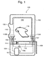
- FIG. 1 is a schematic constitutional view of a drier 100 according to an embodiment of the present invention.
- FIG. 2 is a longitudinal section side view of a rotary compressor (compressor) 10 which constitutes the drier 100 of FIG. 1.
- the drier 100 is used to dry an article 116 to be dried, e.g., a laundry (clothes).
- the drier 100 comprises a main body 102 in an upper side of which a drying chamber 18 is disposed, and a machine chamber 104 disposed in a lower side of the main body 102.
- a rotary drum 110 is disposed to efficiently dry the article 116 by rotating it.
- the rotary compressor 10 is disposed in the machine chamber 104.
- a hollow air circulation path 112 is disposed between the drying chamber 108 and the machine chamber 104 to communicate them with each other.
- An inlet 112A is disposed on one side (right side in the drawing) of the air circulation path 112, and an outlet 112B 8 is disposed on the other side (left side in the drawing).
- the inlet 112A and the outlet 112B are communicated with the insides of the air circulation path 112 and the drying chamber 108.
- An evaporator 157 (dehumidifier) is installed on the inlet 112A side of the air circulation path 112, and a gas cooler 154 (heater) is installed on the outlet side.
- a blower 114 (equivalent to blowing means of the present invention) is installed between the inlet 112A and the outlet 112B of the air circulation path 112.
- the blower 14 constitutes an air circulation in which air of the drying chamber 108 is sucked from the inlet 112A of the air circulation path 112, and sent through the evaporator 157 and the gas cooler 154 into the drying chamber 108 from the outlet 112B of the air circulation path 112.
- the drier 100 supplies the air heated by gas cooler 54 into the drying chamber 108, dries the article 116 in the drying chamber 108, and then cools the air by the evaporator 157.
- a circulation is repeated in which the article 116 to be dried in the drying chamber 108 is dried by the air heated by the gas cooler 154, moisture contained in the dried air is condensed to be eliminated by the evaporator 157 of a low temperature, thereby setting a dehumidified state, and the dehumidified air is heated again by the gas cooler 154 to dry the article 116 in the drying chamber 108.
- a referent numeral 158 denotes a drain pipe to discharge water droplets condensed on the surface of the evaporator 157, and its tip is opened in, e.g., a drain ditch (not shown).
- a reference numeral 106 denotes an opening/closing door used when the article 116 to be dried is taken in or out of the drying chamber 108. It is attached to the front face of the drying chamber 108 of the main body 102 so as to be opened/closed.
- the rotary compressor 10 is an internal middle pressure multistage compression type which uses CO 2 as a refrigerant.
- This rotary compressor 10 comprises, as shown in FIG. 2, a cylindrical airtight container 12 made of a steel plate, an electric element 14 arranged on an upper side of internal space of the airtight container 12, and a rotary compression mechanism section 18 which is arranged below the electric element 14 and which is constituted of a first rotary compression element 32 (first stage) and a second rotary compression element 34 (second stage) driven by a rotary shaft 16 of the electric element 14.
- a height dimension of the rotary compressor 10 is about 220 mm (outer diameter about 120 mm)
- a height dimension of the electric element 14 is about 80 mm (outer diameter about 110 mm)
- a height dimension of the rotary compression mechanism section 18 is about 70 mm (outer diameter about 110 mm)
- an interval between the electric element 14 and the rotary compression mechanism section 18 is about 5 mm.
- an elimination capacity of the second rotary compression element 34 is set smaller than that of the first rotary compression element 32.
- the airtight container 12 is made of a steel plate of a thickness of about 4.5 mm, and a bottom portion is an oil reservoir.
- the airtight container 12 comprises a container main body 12A which contains the electric element 14 and the rotary compression mechanism section 18, and a roughly bowl-shaped end cap (cap body) 12B which closes an upper opening of the container main body 12A.
- a circular attaching hole 12D is formed on an upper surface center of the end cap 12B, and a terminal (wiring is omitted) 20 is fixed to the attaching hole 12D to supply power to the electric element 14.
- a step 12C of a predetermined curvature is formed annularly on the end cap 12B around the terminal 20.
- the terminal 20 comprises a circular glass section 20A through which an electric terminal 139 is attached, and a metal attaching section 20B formed around the glass section 20A and bulged obliquely downward outside in a flange shape.
- a thickness dimension of the attaching section 20B is set to 2.4 ⁇ 0.5 mm.
- the terminal 290 is fixed to the end cap 12B by inserting the glass section 20A into the attaching hole 12D from the lower side to face the upper side, and welding the attaching section 290B to the peripheral edge of the attaching hole 12D of the end cap 12B in a state in which the attaching section 20B is abutted on the peripheral edge of the attaching hole 12D.
- the electric element 14 comprises a stator 22 annularly attached along the inner peripheral surface of the upper space of the airtight container 12, and a rotor 24 inserted and arranged inside the stator 22 with a slight gap.
- the rotor 24 is fixed to a rotary shaft 16 extended through a center in a vertical direction.
- the stator 22 has a laminated body 26 constituted by laminating doughnut-shaped electromagnetic steel plates, and a stator coil 28 wound on the tooth portion of the laminated body 26 by a series-winding (central-winding) method.
- the rotor 24 is constituted of a laminated body 30 of electromagnetic steel plates, and a permanent magnet MG is inserted into the laminated body 30.
- a middle partition plate 36 is held between the first rotary compression element 32 and the second rotary compression element 34. That is, the first rotary compression element 32 and the second rotary compression element 34 comprise the middle partition plate 36, cylinders 38, 40 arranged on and below the middle partition plate 36, upper and lower rollers 46, 48 fitted to upper and lower eccentric sections 42, 44 disposed in the rotary shaft 16 to be eccentrically rotated with a phase difference of 180° in the upper and lower cylinders 38, 40, later-described upper and lower vanes 50 (lower vane is not shown) abutted on the upper and lower rollers 46, 48 to divide the insides of the upper and lower cylinders 38, 40 into low and high pressure chambers, and an upper supporting member 54 and a lower supporting member 56 as supporting members which close the upper opening surface of the upper cylinder 38 and the lower opening surface of the lower cylinder 40 to serve as bearings of the rotary shaft 16.
- suction paths 58, 60 are formed to be communicated with the insides of the upper and lower cylinders 38, 40 through suction ports 161, 162, discharge sound-muffling chambers 62, 64 are formed to be recessed, and openings of the discharge sound-muffling chambers 62, 64 are closed by covers. That is, the discharge sound-muffling chamber 62 is closed by an upper cover 66, and the discharge sound-muffling chamber is closed by a lower cover 68.
- a bearing 54A is erected on a center of the upper supporting member 54, and a cylindrical bush 122 is mounted on the inner surface of the bearing 54A.
- a bearing 56A is formed through a center of the lower supporting member 56, and a cylindrical bush 123 is mounted on the inner surface of the bearing 56A.
- the bushes 122, 123 are made of later-described materials of high sliding characteristics.
- the rotary shaft 16 is held by the bearing 54A of the upper supporting member 54 and the bearing 56A of the lower supporting member 56 through the bushes 122, 123.
- the lower cover 68 is made of a doughnut-shaped circular steel plate, four places of its peripheral portion are fixed to the lower supporting member 56 by main bolts 129 from the lower side, and the cover closes the lower opening of the discharge sound-muffling chamber 64 communicated with the inside of the lower cylinder 40 of the first rotary compression element 32 through a discharge port (not shown). A tip of each main bolt 129 is engaged with the upper supporting member 54.
- the inner peripheral edge of the lower cover 68 is projected inward from the inner surface of the bearing 56A of the lower supporting member 56. Accordingly, the lower end surface of the bush 123 is held by the lower cover 68, whereby its falling-off is prevented.
- the discharge sound-muffling chamber 64 and the inside of the airtight chamber 12 are communicated with each other through a communication path which penetrates the upper and lower cylinders 38, 40 and the middle partition plate 36.
- a discharge pipe 121 is erected on the upper end of the communication path.
- a middle-pressure refrigerant compressed by the first rotary compression element 32 is discharged from the middle discharge pile 121 into the airtight container 12.
- the upper cover 66 closes the upper opening of the discharge sound-muffling chamber 62 communicated with the inside of the upper cylinder 38 of the second rotary compression element 34 through a discharge port 39, and divides the inside of the airtight container 12 into the discharge sound-muffling chamber 62 side and the electric element 14 side.
- the upper cover 66 is made of a roughly doughnut-shaped circular steel plate in which a hole is formed to insert the bearing 54A of the upper supporting member 54 through, and its peripheral portion is fixed to the upper supporting member 54 from above by four main bolts 78. A tip of each main bolt 78 is engaged with the lower supporting member 56.
- a through-hole 131 is bored in a position corresponding to a suction side in the upper cylinder 38 to constitute an oil supply path by communicating the outer peripheral surface with the inner peripheral surface.
- An opening on the outer peripheral surface side of the through-hole 131 is sealed by a pressed-in sealing material 132.
- a communication hole 133 is bored on the middle part of the through-hole 131 to be extended upward.
- a communication hole 134 is bored in a suction port 161 (suction side) of the upper cylinder 38 to be communicated with the communication hole 133 of the middle partition plate 36.
- Horizontal-direction oil supply holes 82, 84 are formed in the rotary shaft 16 (also formed in the upper and lower eccentric sections 42, 44 of the rotary shaft 16) to be communicated with an oil hole formed vertically around an axis. An opening of the inner peripheral surface side of the through-hole 131 of the middle partition plate 36 is communicated through these oil supply holes 82, 84 with the oil hole.
- a guide groove 70 is formed to contain the vane 50, and a housing section 70A is formed outside the guide groove 70 to contain a spring member (spring) 76.
- the spring 76 is abutted on the outside end of the vane 50 to always press the vane 50 to the roller 46 side.
- a metal plug 137 is disposed in the housing section 70A in the airtight container 12 side of the spring 76 to prevent pulling-out of the spring 76.
- sleeves 141, 142, 143 and 144 are welded and fixed to positions corresponding to the suction paths 58, 60 of the upper and lower supporting members 54 and 56, the discharge sound-muffling chamber 62 and the upper side of the upper cover 66 (position roughly corresponding to the lower end of the electric element 14).
- the sleeves 141 and 142 are adjacent to each other up and down, and the sleeve 143 is roughly on a diagonal line of the sleeve 141.
- the sleeve 144 is in a position shifted from the sleeve 141 by roughly 90°.
- a refrigerant introduction pipe 92 is inserted and connected in the sleeve 141 to introduce refrigerant gas into the upper cylinder 38, and communicated with the suction path 58 of the upper cylinder 38.
- the refrigerant introduction pipe 92 passes through the upper side of the airtight container 12 to reach the sleeve 144, and the other end is inserted and connected in the sleeve 144 to be connected with the inside of the airtight container 12.
- a refrigerant introduction pipe 94 is inserted and connected in the sleeve 142 to introduce refrigerant gas into the lower cylinder 40, and communicated with the suction path 60 of the lower cylinder 40.
- the other end of the refrigerant introduction pipe 94 is connected through an accumulator (not shown) to the evaporator 157.
- a refrigerant discharge pipe 96 is inserted and connected in the sleeve 143, and an end of the refrigerant discharge pipe 96 is communicated with the discharge sound-muffling chamber 62.
- flanges 151 are formed to be engaged with couplers for pipe connection, and a thread groove 152 for pipe connection is formed on the inner surface of the sleeve 142.
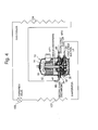
- the rotary compressor 10 disposed in the drier 100 of the embodiment constitutes a refrigerant circuit similar to that shown in FIG. 4, in which a high pressure side of a vapor compression cycle is run at supercritical pressure. That is, the refrigerant discharge pipe 96 of the rotary compressor 10 is connected to an inlet of the gas cooler 154 which heat air to be blown into the drying chamber 108. This gas cooler 154 is disposed in the outlet of the air circulation path 112 as described above. A pipe out of the gas cooler 154 is passed through the expansion valve 156 as the pressure reducing device to reach the inlet of the evaporator 157, and the outlet of the evaporator 157 is connected to the refrigerant introduction pipe 94.
- a predetermined amount of an article 116 to be dried is contained in the drying chamber 108 (in the rotary drum 110).
- a control device is disposed in the machine chamber 104 to control the drier 100.
- the control device controls a temperature of the gas cooler 154 to prevent discoloring, damaging or the like of the article 116 contained in the drying chamber 108, and a temperature of the evaporator 157 to prevent frost generation.
- the middle-pressure refrigerant gas in the airtight container 12 is taken out from the sleeve 144, passed through the refrigerant introduction pipe 92 and the suction path 58 formed in the upper supporting member 54, and sucked from the suction port 161 to the low-pressure chamber side of the upper cylinder 38.
- the sucked middle-pressure refrigerant gas is subjected to compression of the second stage by the operations of the roller 46 and the vane 50 to become refrigerant gas of a high temperature and high pressure. It is passed from the high-pressure chamber side through the discharge port 39, and supplied through the discharge sound-muffling chamber 62 formed in the upper supporting member 54 and the refrigerant discharge pipe 96 into the gas cooler 154.
- the refrigerant is heat-exchanged with air in the air circulation path 112 to be cooled, and then it is discharged from the gas cooler 154. Then, a supercritical cycle is repeated in which after pressure is reduced by the expansion valve 156, the refrigerant flows into the evaporator 157 to be evaporated, and it is sucked from the refrigerant introduction pipe 94 into the first rotary compression element 32. A temperature of the refrigerant when it is introduced is raised to about +90°C to +100°C. This refrigerant gas of the high temperature and the high pressure radiates heat at the gas cooler 154, and air heated by this radiated heat to become a high temperature is blown into the drying chamber 108 by the blower 114.
- the air blown into the drying chamber 108 warms the wet article 116 contained in the rotary drum 110 to evaporate moisture, whereby the article 116 is dried.
- the air which has dried the article 116 and contains moisture is sucked from the inlet 112A of the air circulation path 112 into the same.
- the evaporator 157 is disposed in the inlet 112A of the air circulation path 112. Since a temperature of the evaporation 157 is lowered to about +3°C, the air containing moisture is condensed on the surface in the process of being passed through the evaporator 157 to become water droplets and fall. The fallen water droplets are discharged through the drain pipe 158 to the drain ditch.
- the air dried by removing the moisture at the evaporator 157 is blown to the outlet side of the air circulation path 112 by the blower 114.
- a cycle is repeated in which since the gas cooler 154 is disposed on the outlet side of the air circulation path 112, the dried air is heated again by the gas cooler 154, and blown into the drying chamber 108, and the moisture of the article 116 in the drying chamber 108 is removed to dry the article.
- This cycle is repeated by the control device for a predetermined time, whereby the article 116 in the drying chamber 108 can be completely dried.
- the drier 100 comprises the refrigerant circuit constituted by sequentially installing and connecting the rotary compressor 10, the gas cooler 154, the expansion valve 156 and the evaporator 157 in the annular shape, and the blower 1 which circulates air of the drying chamber 108 to exchange heat with the gas cooler 154 and the evaporator 157, the moisture contained in the air which dries the article 116 contained in the drying chamber 108 can be condensed by the evaporator to be discarded from the drain pipe 158. Therefore, it is possible to greatly increase energy efficiency of the drier 100.
- the article 116 can be quickly dried within a very short time, it is possible to greatly shorten the running time of the drier 100.
- the temperature of the gas cooler 154 can be set very high as described above.
- an increase rate of the temperature of the air circulated in the drying chamber 108 can be enhanced to enable drying of the article 116 contained in the drying chamber 108 within a short time.
- FIG. 5 is an internal constitutional view of a washing drier 200 which executes washing running and drying running after the end of the washing running as another embodiment of a drier to which the present invention is applied.
- the washing drier 200 is used to wash and dry a laundry such as clothes (this laundry becomes an article to be dried during drying running).
- An opening/closing door 203 is attached to the upper surface center of a main body 201 (FIG. 5 shows the inside of a case of the main body 201) which constitutes an outer shell.
- a not-shown operation panel is disposed in which various operation switches and a display section are arranged.
- a cylindrical outer tank drum 202 made of a resin is disposed to store water.
- This outer tank drum 202 is arranged such that a cylindrical shaft is in a left-and-right direction.
- a cylindrical stainless inner tank drum (rotary drum according to the invention) 205 is disposed to serve as a washing tank and a dewatering tank.
- the inside of the inner tank drum 205 is set as a housing chamber (which functions as a drying chamber during drying running) 210 to contain the laundry.
- This drum is also arranged such that a cylindrical shaft is in a left-and-right direction.
- This shaft is connected to a shaft 208 of a not-shown driving motor mounted on the side wall (deep side of FIG.
- the outer tank drum 202 is fixed to a base 302 positioned on the bottom surface of the main body 201 through a suspension 301 which has a vibration absorption function in order to reduce vibration/noise. That is, the rotary inner tank drum 205 is attached to the base 302 through the outer tank drum 202 and the suspension 301.
- a not-shown watertight opening/closing cap is disposed to contain the laundry corresponding to the opening/closing door 203.
- a number of through-holes are formed on a full peripheral wall of the inner tank drum 205 to enable distribution of air and water.
- a stop position of the inner tank drum 205 is defined, and a not-shown opening/closing cap is disposed to take in or out the laundry in a position (upper surface) corresponding to the opening/closing cap of the outer tank drum 202 at time of stoppage thereof.
- the driving motor rotates the inner tank drum 205 around the shaft of the left-and-right horizontal direction during drying washing running and drying running after the end of the washing running.
- the driving motor is attached to one end (deep side of FIG. 5) of the shaft 208, and controlled by a not-shown control device to rotate the inner tank drum 205 at a speed lower compared with that of the washing running during the drying running.
- a hollow portion hollow inside is formed in the other end (front side of FIG. 5) of the shaft 8 and, through this hollow portion, a later-described air circulation path 272 and the inside of the inner tank drum 205 are communicated with each other.
- a not-shown water supply path is disposed as water supply means to supply water into the inner tank drum 205.
- An end of the water supply path is connected through a water supply valve to a water supply source such as tap water. Opening/closing of the water supply valve is controlled by the control device.
- the other end of the water supply path is connected to the outer tank drum 202 to be communicated with the inside.
- a not-shown drain path is disposed as water discharging means to discharge water from the housing chamber 201 in the inner tank drum 205.
- An end of the drain path is communicated with the lowermost portion of the outer tank drum 202 through the drain valve controlled to be opened/closed by the control device.
- the other end of the drain path is lead out to the outside of the washing drier 200 to reach the drain ditch or the like.
- the air circulation path 272 is constituted from the rear side to the side of the outer tank drum 202 in the main body 201.
- This air circulation path 272 comprises a duct member 267 of a discharge side, a duct member 268 of a suction side, an air path 269 formed in a duct box 271, etc.
- An end of the duct member 267 is connected and fixed to the outer tank drum 202 so as to be communicated with the inside (housing chamber 210) of the inner tank drum 205 through the hollow portion formed in the other end (front side of FIG. 5) of the shaft 208.
- the other end is connected and fixed to an outlet 269B of the air path 269 formed in the duct box 271.
- An end of the duct member 268 is connected and fixed to the outer tank drum 202 so as to be communicated with the inside (housing chamber 210) of the inner tank drum 205 in the outer tank drum 202, and the other end is connected and fixed to an inlet 269A of the air path 269.
- Both duct members 267, 268 which constitute the air circulation path 272 are made of metals or heat resisting synthetic resins, and all or at least parts thereof are made of flexible materials, e.g., flexible hoses.
- a blower 114 is disposed as blowing means similar to the foregoing in the duct member 267.
- the blower 114 blows and supplies air of the air circulation path 272 from the duct member 267 of the air circulation path 272 through the hollow portion of the shaft 208 to the housing chamber 272 in the inner tank drum 205. That is, the washing drier 200 circulates the air of the air circulation path 272 into the inner tank drum 205 by the blower 114 during drying running, and thereby discharges the air heated by heat exchange with a gas cooler 154 (radiator) similar to the foregoing, which is disposed in the air path 269 of the air circulation path 272, to the housing chamber 210 in the inner tank drum 205.
- the air path 269 is formed in the duct box 271 as described above. As shown in FIG. 5, the inside of the duct box 271 is divided into a front side and a deep side by a heat insulating partition member 276 in a state in which lower portions thereof are communicated with each other. Accordingly, in the duct box 271, a series of the air path 269 is constituted in a detour form in which it is lowered from the upper side at the front side and then raised from the lower side at the deep side.
- an evaporator 157 similar to the foregoing, of a refrigerant circuit 220 of this case is disposed on the front side of the air path 269, and the gas cooler 154 of the refrigerant circuit 220 is disposed on the deep side.
- An inlet 269A of the air path 269 is opened in the upper side of the air path 269 on the front side of the duct box 271, whereby the duct member 268 is communicated with the upper side of the air path 269 on the front side of the duct box 271.
- An outlet 269B of the air path 269 is opened in the upper side of the air path 269 on the deep side of the duct box 271, whereby the duct member 267 is communicated with the upper side of the air path 269 on the deep side of the duct box 271.
- the air which has been circulated in the housing chamber 210 by running the blower 114 and dried the laundry is passed through the duct member 268 of the air circulation path 272 to flow from the inlet 269A into the air path 269 on the front side of the duct box 271. It is then lowered to exchange heat with the evaporator 157 disposed in the air path 269 on the front side to be cooled. After dehumidified, the air enters the air path 269 on the deep side of the duct box 271 from the lower side of the partition member 276. It is then raised to exchange heat with the gas cooler 154 disposed in the air path 269 on the deep side to be heated. Then, the air is discharged from the outlet 269B to enter the duct member 267, sucked by the blower 114 disposed therein, and discharged from the blower 114 into the housing chamber 210.
- a reference numeral 220 denotes the refrigerant circuit.
- the refrigerant circuit 220 is constituted by sequentially installing and connecting the rotary compressor 10 similar to the foregoing, the gas cooler 154, an expansion valve 156 as a pressure reducing device similar to the foregoing, the evaporator 157, etc.
- the duct box 271 which incorporates the rotary compressor 10, the expansion valve 156, the gas cooler 154 and the evaporator 157 is attached to a base 302 to be fixed.
- a predetermined amount of carbon dioxide (CO 2 is sealed as a refrigerant in the refrigerant circuit 220.
- a low-pressure refrigerant is introduced from a refrigerant introduction pipe 230 into a rotary compression element 32 of the rotary compressor 10, and a refrigerant of a high temperature and high pressure compressed by a second rotary compression element is discharged from a refrigerant discharge pipe 232 to the outside of the rotary compressor.
- the refrigerant discharge pipe 232 of the rotary compressor 10 of the refrigerant circuit 220 is connected to an inlet of the gas cooler 154 for heating air.
- a pipe 330 out of the gas cooler 154 is connected to an inlet of the expansion valve 156, a pipe out of the expansion valve 156 reaches an inlet of the evaporator 157, and a pipe out of the evaporator 157 is connected to the refrigerant introduction pipe 230 to reach the rotary compressor 10.
- Running of the rotary compressor 10 and the expansion valve 156 are controlled by the control device.
- the control device is control means for controlling the washing drier 200, and controls running of a not-shown driving motor, opening/closing of a water supply valve of a water supply path, opening/closing of a drain valve of a drain path, running of the rotary compressor 10, diaphragm adjustment of the expansion valve 156, and the blowing amount of the blower 114. Further, the control device controls a temperature of air passed through the gas cooler 154 to prevent discoloring or damaging of the laundry contained in the inner tank drum 205.
- the control device starts washing running. Then, the control device opens a water supply valve of a not-shown water supply path to open it. Accordingly, water is supplied from the water supply source into the housing chamber 210 of the inner tank drum 205 in the outer tank drum 202. At this time, the drain valve of the drain path is closed by the control device.
- the control device closes the water supply valve to close the water supply path.
- the supplying of water from the water supply source is stopped.
- control device supplies power and starts the driving motor formed on the side face of the main body 201 to rotate the shaft 208, whereby the inner tank drum 205 attached to the shaft 208 starts to rotate in the outer tank drum 202, and washing step of the washing running is started.
- the control device stops the driving motor, and opens the drain valve of the drain path to discharge the water (washing water) from the housing chamber 210 of the inner tank drum 202 (i.e., outer tank drum 205).
- the control device actuates the driving motor again to dehydrate the laundry. After this dehydration is carried out for a predetermined time, the control device closes the drain valve of the drain path.
- control device proceeds to a rinsing step, where the water supply valve of the water supply path is opened to open the water supply path.
- water is supplied again from the water supply source into the housing chamber 210 of the inner tank drum 205.
- the control device closes the water supply valve to close the water supply path. Accordingly, the supplying of water from the water supply source is stopped.
- the control device stops the driving motor, and opens the drain valve of the drain path to discharge the rinsing water from the housing chamber 210 to the drain path. After the discharging of the rinsing water from the housing chamber 210, the control device actuates the driving motor again to rotate the inner tank drum 205 as in the previous case, and then proceeds to a dehydration step, where the laundry is dehydrated.
- the control device closes the drain valve.
- the control device actuates the rotary compressor 10, and starts running of the blower 114.
- the inner tank drum 205 is rotated by the driving motor to start drying running.
- a cycle is executed in which refrigerant gas of a high temperature and high pressure discharged from the rotary compressor 10 radiates heat at the gas cooler 154, pressure is reduced by the expansion valve 156, and then the refrigerant flows into the evaporator 157 to absorb heat from the surroundings, and evaporated to be sucked from the refrigerant introduction pipe 232 into the first rotary compression element 32 of the rotary compressor 10.
- the heated air discharged from the housing chamber 210 warms the laundry contained in the inner tank drum 205 (housing chamber 210) to evaporate moisture, whereby the laundry (article to be dried) is dried.
- the air which has dried the laundry and contains moisture is passed through the housing chamber 210, passed through a not-shown through-hole to exit from the inner tank drum 205, passed through the duct member 268 of the air circulation path 272 to be sucked from the inlet 269A into the air path 269, and introduced to the evaporator 157 disposed therein to be passed.
- the moisture (moisture evaporated from the laundry) contained in the air from the housing chamber 210 is condensed on the surface of the evaporator 157 in the process of being passed through the evaporator 157 to become water droplets and fall.
- the fallen water droplets are discharged from the drain path through a not-shown drain pipe to the external drain ditch or the like.
- the air which has been dried by the moisture removal at the evaporator 157 then flows into the gas cooler 154 to be heated. Then, a cycle is repeated in which the air exits from the outlet 269B of the air path 269 to enter the duct member 267, sucked by the blower 114 to be blown to the hollow portion side of the shaft 208, and discharged to the housing chamber 210 in the inner tank drum 205 to remove moisture from the laundry in the inner tank drum 105, and to dry it.
- the laundry in the housing chamber 210 of the inner tank drum 205 is completely dried.
- it is possible to efficiently dry the laundry by heating the air in the air circulation path 272 at the gas cooler 154 and dehumidifying it at the evaporator 157.
- the refrigerant such as carbon dioxide in which the high pressure side of the refrigerant circuit becomes supercritical pressure, it is possible to obtain a large heating ability at the gas cooler 154.
- the rotation of the inner tank drum 205 causes vibration and displacement in the outer tank drum 202 and the inner tank drum 205. However, such vibration and displacement are absorbed by a suspension 301. Thus, vibration transmitted to the base 302 is softened to reduce noise.
- the vibration/displacement of the inner tank drum 205 and the outer tank drum 202 causes shifting in the positions of the duct box 271 and the outer tank drum 202 attached to the base 302. Consequently, positional relations between ends and the other ends of the duct members 267, 268 are changed.
- the duct members 267a and 268 are flexible, even when the inner tank drum 205 and the outer tank drum are vibrated or displaced by rotation, the duct members 267, 268 can absorb the vibration or displacement themselves. Thus, it is possible to prevent a problem of damaging in the connection places of the duct members 267, 268 to the duct box 271 and the outer tank drum 202.
- the rotary compressor of the internal middle pressure multistage (two stages) compression type which comprises the first and second rotary compression elements 32, 34 is used.
- a compressor to be used for the present invention is not limited to this.
- the drier which comprises the drying chamber to hose the article to be dried comprises the refrigerant circuit constituted by sequentially installing and connecting the compressor, the gas cooler, the pressure reducing device and the evaporator in the annular shape, and the blowing means which circulates air of the drying chamber to exchange heat with the gas cooler and the evaporator, the article contained in the drying chamber is heated by the high-temperature air heated by the gas cooler, and the moisture evaporated from the article can be condensed by the evaporator to be discarded.
- the temperature of the gas cooler can be set very high as described above.
- the temperature of the gas cooler can be set very high as described above.
- the rotary drum is disposed which is attached to the base through the suspension for vibration absorption, and in which the drying chamber is constituted inside, components constituting the refrigerant circuit are attached to the base, and the duct member which supplies the air heat-exchanged with the gas cooler and introduces the air passed through the drying chamber into the evaporator is flexible, even when the rotary drum is vibrated or displaced with respect to the base by rotation, since the duct member can absorb the vibration or displacement itself, it is possible to prevent a problem of damaging in the connection place of the duct member.
Landscapes
- Engineering & Computer Science (AREA)
- Mechanical Engineering (AREA)
- General Engineering & Computer Science (AREA)
- Textile Engineering (AREA)
- Detail Structures Of Washing Machines And Dryers (AREA)
- Drying Of Solid Materials (AREA)
Abstract
Description
- The present invention relates to a drier which comprises a drying chamber which contain an article to be dried.
- Conventionally, a general drier similar to that described in Jpn. Pat. Appln. KOKAI Publication No. 2002-336594 has dried an article to be dried in a drying chamber by using an electric heater or a combustion heater as a heat source, heating outside air by the heat source of such an electric heater or a combustion heater to make it high-temperature air, and then blowing it into the drying chamber which contains the article to be dried. Then, the high-temperature air in the drying chamber which has dried the article to be dried is discharged to the outside.
- However, in the drier which uses such an electric heater or a combustion heater, moisture-containing outside air in which a temperature outside the drying chamber is low is used for the high-temperature air sent into the drying chamber. It consequently takes a long timed for the article to be dried. Thus, the amount of energy consumption to dry the article is large, which creates a problem of a high rise in energy costs such as electricity bills or gas bills.
- The high-temperature air which has dried the article is discharged indoors or outdoors outside the drying chamber. Thus, in the case of discharging the high-temperature air indoors, a temperature and humidity in a room in which the drier has been installed are increased to deteriorate an in-room environment. In the case of discharging the high-temperature air outdoors, an exhaust duct must be laid from the drier to the outdoors, which creates a problem of a high rise in equipment costs.
- The present invention has been developed to solve the problems of the prior art, and an object of the present invention is to provide a drier which can shorten drying time of an article to be dried to greatly reduce the amount of energy consumption.
- A first aspect of the present invention is directed to a drier which is equipped with a drying chamber for containing an article to be dried, comprising a refrigerant circuit constituted by sequentially installing and connecting a compressor, a gas cooler, a pressure reducing device and an evaporator in an annular shape; and blowing means for circulating air in the drying chamber to exchange heat with the gas cooler and the evaporator.
- A second aspect of the present invention is directed to the above drier, wherein a CO2 refrigerant is sealed in the refrigerant circuit.
- A third aspect of the present invention is directed to the above drier further comprising a rotary drum which is attached to a base through a suspension for vibration absorption and in which the drying chamber is installed, wherein components constituting the refrigerant circuit are attached to the base, the air heat-exchanged with the gas cooler is supplied into the drying chamber, and a duct member for introducing the air passed through the drying chamber into the evaporator is flexible.
-
- FIG. 1 is a schematic constitutional view of a drier according to an embodiment of the present invention (first embodiment).
- FIG. 2 is a longitudinal section side view of a rotary compressor which constitutes the drier of FIG. 1.
- FIG. 3 is a conceptual view showing a compression step of a second rotary compression element of the rotary compressor of FIG. 2.
- FIG. 4 is a refrigerant circuit diagram of the drier of FIG. 1.
- FIG. 5 is a perspective view showing an internal constitution of a washing drier according to another embodiment of the present invention (second embodiment).
-
- Next, the preferred embodiments of the present invention will be described in detail with reference to the accompanying drawings.
- FIG. 1 is a schematic constitutional view of a
drier 100 according to an embodiment of the present invention. FIG. 2 is a longitudinal section side view of a rotary compressor (compressor) 10 which constitutes thedrier 100 of FIG. 1. Thedrier 100 is used to dry anarticle 116 to be dried, e.g., a laundry (clothes). Thedrier 100 comprises amain body 102 in an upper side of which adrying chamber 18 is disposed, and amachine chamber 104 disposed in a lower side of themain body 102. In themain body 102, arotary drum 110 is disposed to efficiently dry thearticle 116 by rotating it. Therotary compressor 10 is disposed in themachine chamber 104. A hollowair circulation path 112 is disposed between thedrying chamber 108 and themachine chamber 104 to communicate them with each other. - An
inlet 112A is disposed on one side (right side in the drawing) of theair circulation path 112, and anoutlet 112B 8 is disposed on the other side (left side in the drawing). Theinlet 112A and theoutlet 112B are communicated with the insides of theair circulation path 112 and thedrying chamber 108. An evaporator 157 (dehumidifier) is installed on theinlet 112A side of theair circulation path 112, and a gas cooler 154 (heater) is installed on the outlet side. A blower 114 (equivalent to blowing means of the present invention) is installed between theinlet 112A and theoutlet 112B of theair circulation path 112. - As indicated by arrows in FIG. 1, the
blower 14 constitutes an air circulation in which air of thedrying chamber 108 is sucked from theinlet 112A of theair circulation path 112, and sent through theevaporator 157 and thegas cooler 154 into thedrying chamber 108 from theoutlet 112B of theair circulation path 112. By circulating the air of thedrying chamber 108 through theair circulation path 112 by theblower 114, thedrier 100 supplies the air heated by gas cooler 54 into thedrying chamber 108, dries thearticle 116 in thedrying chamber 108, and then cools the air by theevaporator 157. - That is, a circulation is repeated in which the
article 116 to be dried in thedrying chamber 108 is dried by the air heated by thegas cooler 154, moisture contained in the dried air is condensed to be eliminated by theevaporator 157 of a low temperature, thereby setting a dehumidified state, and the dehumidified air is heated again by thegas cooler 154 to dry thearticle 116 in thedrying chamber 108. Areferent numeral 158 denotes a drain pipe to discharge water droplets condensed on the surface of theevaporator 157, and its tip is opened in, e.g., a drain ditch (not shown). Areference numeral 106 denotes an opening/closing door used when thearticle 116 to be dried is taken in or out of thedrying chamber 108. It is attached to the front face of thedrying chamber 108 of themain body 102 so as to be opened/closed. - On the other hand, the
rotary compressor 10, theevaporator 157, theexpansion valve 156 and thegas cooler 154 are installed and connected in an annular shape to constitute a refrigerant circuit shown in FIG. 4. Therotary compressor 10 is an internal middle pressure multistage compression type which uses CO2 as a refrigerant. Thisrotary compressor 10 comprises, as shown in FIG. 2, acylindrical airtight container 12 made of a steel plate, anelectric element 14 arranged on an upper side of internal space of theairtight container 12, and a rotarycompression mechanism section 18 which is arranged below theelectric element 14 and which is constituted of a first rotary compression element 32 (first stage) and a second rotary compression element 34 (second stage) driven by arotary shaft 16 of theelectric element 14. - According to the embodiment, a height dimension of the
rotary compressor 10 is about 220 mm (outer diameter about 120 mm), a height dimension of theelectric element 14 is about 80 mm (outer diameter about 110 mm), a height dimension of the rotarycompression mechanism section 18 is about 70 mm (outer diameter about 110 mm), and an interval between theelectric element 14 and the rotarycompression mechanism section 18 is about 5 mm. Additionally, an elimination capacity of the secondrotary compression element 34 is set smaller than that of the firstrotary compression element 32. - According to the embodiment, the
airtight container 12 is made of a steel plate of a thickness of about 4.5 mm, and a bottom portion is an oil reservoir. Theairtight container 12 comprises a containermain body 12A which contains theelectric element 14 and the rotarycompression mechanism section 18, and a roughly bowl-shaped end cap (cap body) 12B which closes an upper opening of the containermain body 12A. A circular attachinghole 12D is formed on an upper surface center of theend cap 12B, and a terminal (wiring is omitted) 20 is fixed to the attachinghole 12D to supply power to theelectric element 14. - In this case, a
step 12C of a predetermined curvature is formed annularly on theend cap 12B around theterminal 20. Theterminal 20 comprises acircular glass section 20A through which anelectric terminal 139 is attached, and ametal attaching section 20B formed around theglass section 20A and bulged obliquely downward outside in a flange shape. A thickness dimension of the attachingsection 20B is set to 2.4±0.5 mm. The terminal 290 is fixed to theend cap 12B by inserting theglass section 20A into the attachinghole 12D from the lower side to face the upper side, and welding the attaching section 290B to the peripheral edge of the attachinghole 12D of theend cap 12B in a state in which the attachingsection 20B is abutted on the peripheral edge of the attachinghole 12D. - The
electric element 14 comprises astator 22 annularly attached along the inner peripheral surface of the upper space of theairtight container 12, and arotor 24 inserted and arranged inside thestator 22 with a slight gap. Therotor 24 is fixed to arotary shaft 16 extended through a center in a vertical direction. - The
stator 22 has a laminatedbody 26 constituted by laminating doughnut-shaped electromagnetic steel plates, and astator coil 28 wound on the tooth portion of the laminatedbody 26 by a series-winding (central-winding) method. As in the case of thestator 22, therotor 24 is constituted of a laminatedbody 30 of electromagnetic steel plates, and a permanent magnet MG is inserted into the laminatedbody 30. - A
middle partition plate 36 is held between the firstrotary compression element 32 and the secondrotary compression element 34. That is, the firstrotary compression element 32 and the secondrotary compression element 34 comprise themiddle partition plate 36,cylinders middle partition plate 36, upper andlower rollers 46, 48 fitted to upper and lowereccentric sections 42, 44 disposed in therotary shaft 16 to be eccentrically rotated with a phase difference of 180° in the upper andlower cylinders lower rollers 46, 48 to divide the insides of the upper andlower cylinders member 56 as supporting members which close the upper opening surface of theupper cylinder 38 and the lower opening surface of thelower cylinder 40 to serve as bearings of therotary shaft 16. - In the upper supporting member 54 and the lower supporting
member 56,suction paths 58, 60 are formed to be communicated with the insides of the upper andlower cylinders suction ports muffling chambers muffling chambers muffling chamber 62 is closed by anupper cover 66, and the discharge sound-muffling chamber is closed by alower cover 68. - In this case, a
bearing 54A is erected on a center of the upper supporting member 54, and acylindrical bush 122 is mounted on the inner surface of thebearing 54A. Abearing 56A is formed through a center of the lower supportingmember 56, and acylindrical bush 123 is mounted on the inner surface of thebearing 56A. Thebushes rotary shaft 16 is held by thebearing 54A of the upper supporting member 54 and thebearing 56A of the lower supportingmember 56 through thebushes - In this case, the
lower cover 68 is made of a doughnut-shaped circular steel plate, four places of its peripheral portion are fixed to the lower supportingmember 56 bymain bolts 129 from the lower side, and the cover closes the lower opening of the discharge sound-mufflingchamber 64 communicated with the inside of thelower cylinder 40 of the firstrotary compression element 32 through a discharge port (not shown). A tip of eachmain bolt 129 is engaged with the upper supporting member 54. - The inner peripheral edge of the
lower cover 68 is projected inward from the inner surface of thebearing 56A of the lower supportingmember 56. Accordingly, the lower end surface of thebush 123 is held by thelower cover 68, whereby its falling-off is prevented. The discharge sound-mufflingchamber 64 and the inside of theairtight chamber 12 are communicated with each other through a communication path which penetrates the upper andlower cylinders middle partition plate 36. A discharge pipe 121 is erected on the upper end of the communication path. A middle-pressure refrigerant compressed by the firstrotary compression element 32 is discharged from the middle discharge pile 121 into theairtight container 12. - The
upper cover 66 closes the upper opening of the discharge sound-mufflingchamber 62 communicated with the inside of theupper cylinder 38 of the secondrotary compression element 34 through adischarge port 39, and divides the inside of theairtight container 12 into the discharge sound-mufflingchamber 62 side and theelectric element 14 side. Theupper cover 66 is made of a roughly doughnut-shaped circular steel plate in which a hole is formed to insert thebearing 54A of the upper supporting member 54 through, and its peripheral portion is fixed to the upper supporting member 54 from above by fourmain bolts 78. A tip of eachmain bolt 78 is engaged with the lower supportingmember 56. - In the
middle partition plate 36 which closes the lower opening surface of theupper cylinder 38 and the upper opening surface of thelower cylinder 40, a through-hole 131 is bored in a position corresponding to a suction side in theupper cylinder 38 to constitute an oil supply path by communicating the outer peripheral surface with the inner peripheral surface. An opening on the outer peripheral surface side of the through-hole 131 is sealed by a pressed-insealing material 132. Acommunication hole 133 is bored on the middle part of the through-hole 131 to be extended upward. - On the other hand, a
communication hole 134 is bored in a suction port 161 (suction side) of theupper cylinder 38 to be communicated with thecommunication hole 133 of themiddle partition plate 36. Horizontal-direction oil supply holes 82, 84 are formed in the rotary shaft 16 (also formed in the upper and lowereccentric sections 42, 44 of the rotary shaft 16) to be communicated with an oil hole formed vertically around an axis. An opening of the inner peripheral surface side of the through-hole 131 of themiddle partition plate 36 is communicated through these oil supply holes 82, 84 with the oil hole. - As the inside of the
airtight container 12 is se to middle pressure as described later, supplying of oil into theupper cylinder 38 which is set to high pressure at the second stage. However, because of the aforementioned constitution of themiddle partition plate 36, oil scooped up from the oil reservoir on the bottom in theairtight container 12 is raised through the oil hole. The oil discharged out of the oil supply holes 82, 84 enters the through-hole 131 of themiddle partition plate 36, and the oil is supplied through the communication holes 133, 134 to the suction side (suction port 161) of theupper cylinder 38. - On the other hand, in the
upper cylinder 38, aguide groove 70 is formed to contain thevane 50, and ahousing section 70A is formed outside theguide groove 70 to contain a spring member (spring) 76. The spring 76 is abutted on the outside end of thevane 50 to always press thevane 50 to theroller 46 side. Ametal plug 137 is disposed in thehousing section 70A in theairtight container 12 side of the spring 76 to prevent pulling-out of the spring 76. - On the side face of the container
main body 12A of theairtight container 12,sleeves suction paths 58, 60 of the upper and lower supportingmembers 54 and 56, the discharge sound-mufflingchamber 62 and the upper side of the upper cover 66 (position roughly corresponding to the lower end of the electric element 14). Thesleeves sleeve 143 is roughly on a diagonal line of thesleeve 141. Thesleeve 144 is in a position shifted from thesleeve 141 by roughly 90°. - An end of a
refrigerant introduction pipe 92 is inserted and connected in thesleeve 141 to introduce refrigerant gas into theupper cylinder 38, and communicated with the suction path 58 of theupper cylinder 38. Therefrigerant introduction pipe 92 passes through the upper side of theairtight container 12 to reach thesleeve 144, and the other end is inserted and connected in thesleeve 144 to be connected with the inside of theairtight container 12. - An end of a
refrigerant introduction pipe 94 is inserted and connected in thesleeve 142 to introduce refrigerant gas into thelower cylinder 40, and communicated with thesuction path 60 of thelower cylinder 40. The other end of therefrigerant introduction pipe 94 is connected through an accumulator (not shown) to theevaporator 157. Additionally, arefrigerant discharge pipe 96 is inserted and connected in thesleeve 143, and an end of therefrigerant discharge pipe 96 is communicated with the discharge sound-mufflingchamber 62. - Around the outer surfaces of the
sleeves flanges 151 are formed to be engaged with couplers for pipe connection, and athread groove 152 for pipe connection is formed on the inner surface of thesleeve 142. Thus, when an airtight test is carried out in completion inspection of the manufacturing process of therotary compressor 10, the couplers of test pipes can be easily connected to theflanges 151 in thesleeves thread groove 152 in thesleeve 142. - The
rotary compressor 10 disposed in the drier 100 of the embodiment constitutes a refrigerant circuit similar to that shown in FIG. 4, in which a high pressure side of a vapor compression cycle is run at supercritical pressure. That is, therefrigerant discharge pipe 96 of therotary compressor 10 is connected to an inlet of thegas cooler 154 which heat air to be blown into the dryingchamber 108. This gas cooler 154 is disposed in the outlet of theair circulation path 112 as described above. A pipe out of thegas cooler 154 is passed through theexpansion valve 156 as the pressure reducing device to reach the inlet of theevaporator 157, and the outlet of theevaporator 157 is connected to therefrigerant introduction pipe 94. - Next, an operation in the foregoing constitution will be described. A predetermined amount of an
article 116 to be dried is contained in the drying chamber 108 (in the rotary drum 110). A control device is disposed in themachine chamber 104 to control the drier 100. The control device controls a temperature of thegas cooler 154 to prevent discoloring, damaging or the like of thearticle 116 contained in the dryingchamber 108, and a temperature of theevaporator 157 to prevent frost generation. When power is supplied to thestator coil 28 of theelectric element 14 through the terminal 20 and a not-shown wiring, therotary drum 110 is rotated, and theelectric element 14 is actuated to rotate therotor 24. By this rotation, the upper andlower rollers 46, 48 fitted to the upper and lowereccentric sections 42, 44 integrally disposed with therotary shaft 16 are eccentrically rotated in the upper andlower cylinders - Accordingly, low-pressure refrigerant gas sucked from the
suction port 162 to the low-pressure chamber side of thelower cylinder 40 through therefrigerant introduction pipe 94 and thesuction path 60 formed in the lower supportingmember 56 is compressed by the roller 48 and a vane operation to become middle pressure, passed from the high-pressure chamber side of thelower cylinder 40 to the discharge port, passed from the discharge sound-mufflingchamber 64 formed in the lower supportingmember 56 to the communication path, and discharged through the middle discharge pipe 121 into theairtight container 12. Thus, middle pressure is set in theairtight container 12. - Then, the middle-pressure refrigerant gas in the
airtight container 12 is taken out from thesleeve 144, passed through therefrigerant introduction pipe 92 and the suction path 58 formed in the upper supporting member 54, and sucked from thesuction port 161 to the low-pressure chamber side of theupper cylinder 38. The sucked middle-pressure refrigerant gas is subjected to compression of the second stage by the operations of theroller 46 and thevane 50 to become refrigerant gas of a high temperature and high pressure. It is passed from the high-pressure chamber side through thedischarge port 39, and supplied through the discharge sound-mufflingchamber 62 formed in the upper supporting member 54 and therefrigerant discharge pipe 96 into thegas cooler 154. - At the
gas cooler 154, the refrigerant is heat-exchanged with air in theair circulation path 112 to be cooled, and then it is discharged from thegas cooler 154. Then, a supercritical cycle is repeated in which after pressure is reduced by theexpansion valve 156, the refrigerant flows into theevaporator 157 to be evaporated, and it is sucked from therefrigerant introduction pipe 94 into the firstrotary compression element 32. A temperature of the refrigerant when it is introduced is raised to about +90°C to +100°C. This refrigerant gas of the high temperature and the high pressure radiates heat at thegas cooler 154, and air heated by this radiated heat to become a high temperature is blown into the dryingchamber 108 by theblower 114. - The air blown into the drying
chamber 108 warms thewet article 116 contained in therotary drum 110 to evaporate moisture, whereby thearticle 116 is dried. The air which has dried thearticle 116 and contains moisture is sucked from theinlet 112A of theair circulation path 112 into the same. Theevaporator 157 is disposed in theinlet 112A of theair circulation path 112. Since a temperature of theevaporation 157 is lowered to about +3°C, the air containing moisture is condensed on the surface in the process of being passed through theevaporator 157 to become water droplets and fall. The fallen water droplets are discharged through thedrain pipe 158 to the drain ditch. - The air dried by removing the moisture at the
evaporator 157 is blown to the outlet side of theair circulation path 112 by theblower 114. A cycle is repeated in which since thegas cooler 154 is disposed on the outlet side of theair circulation path 112, the dried air is heated again by thegas cooler 154, and blown into the dryingchamber 108, and the moisture of thearticle 116 in the dryingchamber 108 is removed to dry the article. This cycle is repeated by the control device for a predetermined time, whereby thearticle 116 in the dryingchamber 108 can be completely dried. - Thus, since the drier 100 comprises the refrigerant circuit constituted by sequentially installing and connecting the
rotary compressor 10, thegas cooler 154, theexpansion valve 156 and theevaporator 157 in the annular shape, and the blower 1 which circulates air of the dryingchamber 108 to exchange heat with thegas cooler 154 and theevaporator 157, the moisture contained in the air which dries thearticle 116 contained in the dryingchamber 108 can be condensed by the evaporator to be discarded from thedrain pipe 158. Therefore, it is possible to greatly increase energy efficiency of the drier 100. - Since the
article 116 can be quickly dried within a very short time, it is possible to greatly shorten the running time of the drier 100. - Furthermore, since the CO2 refrigerant is sealed in the refrigerant circuit, the temperature of the
gas cooler 154 can be set very high as described above. Thus, an increase rate of the temperature of the air circulated in the dryingchamber 108 can be enhanced to enable drying of thearticle 116 contained in the dryingchamber 108 within a short time. - FIG. 5 is an internal constitutional view of a washing drier 200 which executes washing running and drying running after the end of the washing running as another embodiment of a drier to which the present invention is applied. According to the embodiment, the washing drier 200 is used to wash and dry a laundry such as clothes (this laundry becomes an article to be dried during drying running). An opening/
closing door 203 is attached to the upper surface center of a main body 201 (FIG. 5 shows the inside of a case of the main body 201) which constitutes an outer shell. On the upper surface of themain body 201 of the opening/closing door 203 side, a not-shown operation panel is disposed in which various operation switches and a display section are arranged. - In the
main body 201, a cylindricalouter tank drum 202 made of a resin is disposed to store water. Thisouter tank drum 202 is arranged such that a cylindrical shaft is in a left-and-right direction. In theouter tank drum 202, a cylindrical stainless inner tank drum (rotary drum according to the invention) 205 is disposed to serve as a washing tank and a dewatering tank. The inside of theinner tank drum 205 is set as a housing chamber (which functions as a drying chamber during drying running) 210 to contain the laundry. This drum is also arranged such that a cylindrical shaft is in a left-and-right direction. This shaft is connected to ashaft 208 of a not-shown driving motor mounted on the side wall (deep side of FIG. 5) of theouter tank drum 202, and theinner tank drum 205 is held so as to be rotated around theshaft 208 in theouter tank drum 202. Since vibration/displacement occurs by the rotation of theinner tank drum 205, theouter tank drum 202 is fixed to a base 302 positioned on the bottom surface of themain body 201 through asuspension 301 which has a vibration absorption function in order to reduce vibration/noise. That is, the rotaryinner tank drum 205 is attached to the base 302 through theouter tank drum 202 and thesuspension 301. - On the upper side of the
outer tank drum 202, a not-shown watertight opening/closing cap is disposed to contain the laundry corresponding to the opening/closing door 203. A number of through-holes (not shown) are formed on a full peripheral wall of theinner tank drum 205 to enable distribution of air and water. A stop position of theinner tank drum 205 is defined, and a not-shown opening/closing cap is disposed to take in or out the laundry in a position (upper surface) corresponding to the opening/closing cap of theouter tank drum 202 at time of stoppage thereof. - The driving motor rotates the
inner tank drum 205 around the shaft of the left-and-right horizontal direction during drying washing running and drying running after the end of the washing running. The driving motor is attached to one end (deep side of FIG. 5) of theshaft 208, and controlled by a not-shown control device to rotate theinner tank drum 205 at a speed lower compared with that of the washing running during the drying running. - A hollow portion hollow inside is formed in the other end (front side of FIG. 5) of the shaft 8 and, through this hollow portion, a later-described
air circulation path 272 and the inside of theinner tank drum 205 are communicated with each other. - On the upper side of the
main body 201, a not-shown water supply path is disposed as water supply means to supply water into theinner tank drum 205. An end of the water supply path is connected through a water supply valve to a water supply source such as tap water. Opening/closing of the water supply valve is controlled by the control device. The other end of the water supply path is connected to theouter tank drum 202 to be communicated with the inside. When the water supply valve is opened by the control device, water (tap water) is supplied from the water supply source to thehousing chamber 210 in theinner tank drum 205 disposed in theouter tank drum 202. - On the lower side of the
main body 201, a not-shown drain path is disposed as water discharging means to discharge water from thehousing chamber 201 in theinner tank drum 205. An end of the drain path is communicated with the lowermost portion of theouter tank drum 202 through the drain valve controlled to be opened/closed by the control device. The other end of the drain path is lead out to the outside of the washing drier 200 to reach the drain ditch or the like. - On the other hand, in the washing drier 200, the
air circulation path 272 is constituted from the rear side to the side of theouter tank drum 202 in themain body 201. Thisair circulation path 272 comprises aduct member 267 of a discharge side, aduct member 268 of a suction side, anair path 269 formed in aduct box 271, etc. An end of theduct member 267 is connected and fixed to theouter tank drum 202 so as to be communicated with the inside (housing chamber 210) of theinner tank drum 205 through the hollow portion formed in the other end (front side of FIG. 5) of theshaft 208. The other end is connected and fixed to anoutlet 269B of theair path 269 formed in theduct box 271. An end of theduct member 268 is connected and fixed to theouter tank drum 202 so as to be communicated with the inside (housing chamber 210) of theinner tank drum 205 in theouter tank drum 202, and the other end is connected and fixed to aninlet 269A of theair path 269. - Both
duct members air circulation path 272 are made of metals or heat resisting synthetic resins, and all or at least parts thereof are made of flexible materials, e.g., flexible hoses. - A
blower 114 is disposed as blowing means similar to the foregoing in theduct member 267. Theblower 114 blows and supplies air of theair circulation path 272 from theduct member 267 of theair circulation path 272 through the hollow portion of theshaft 208 to thehousing chamber 272 in theinner tank drum 205. That is, the washing drier 200 circulates the air of theair circulation path 272 into theinner tank drum 205 by theblower 114 during drying running, and thereby discharges the air heated by heat exchange with a gas cooler 154 (radiator) similar to the foregoing, which is disposed in theair path 269 of theair circulation path 272, to thehousing chamber 210 in theinner tank drum 205. - The
air path 269 is formed in theduct box 271 as described above. As shown in FIG. 5, the inside of theduct box 271 is divided into a front side and a deep side by a heat insulatingpartition member 276 in a state in which lower portions thereof are communicated with each other. Accordingly, in theduct box 271, a series of theair path 269 is constituted in a detour form in which it is lowered from the upper side at the front side and then raised from the lower side at the deep side. Then, anevaporator 157, similar to the foregoing, of arefrigerant circuit 220 of this case is disposed on the front side of theair path 269, and thegas cooler 154 of therefrigerant circuit 220 is disposed on the deep side. - As described above, the lower sides of the
gas cooler 154 and theevaporator 157 are not divided by thepartition member 267 but communicated with each other. Aninlet 269A of theair path 269 is opened in the upper side of theair path 269 on the front side of theduct box 271, whereby theduct member 268 is communicated with the upper side of theair path 269 on the front side of theduct box 271. Anoutlet 269B of theair path 269 is opened in the upper side of theair path 269 on the deep side of theduct box 271, whereby theduct member 267 is communicated with the upper side of theair path 269 on the deep side of theduct box 271. - Thus, the air which has been circulated in the
housing chamber 210 by running theblower 114 and dried the laundry is passed through theduct member 268 of theair circulation path 272 to flow from theinlet 269A into theair path 269 on the front side of theduct box 271. It is then lowered to exchange heat with theevaporator 157 disposed in theair path 269 on the front side to be cooled. After dehumidified, the air enters theair path 269 on the deep side of theduct box 271 from the lower side of thepartition member 276. It is then raised to exchange heat with thegas cooler 154 disposed in theair path 269 on the deep side to be heated. Then, the air is discharged from theoutlet 269B to enter theduct member 267, sucked by theblower 114 disposed therein, and discharged from theblower 114 into thehousing chamber 210. - A
reference numeral 220 denotes the refrigerant circuit. Therefrigerant circuit 220 is constituted by sequentially installing and connecting therotary compressor 10 similar to the foregoing, thegas cooler 154, anexpansion valve 156 as a pressure reducing device similar to the foregoing, theevaporator 157, etc. Theduct box 271 which incorporates therotary compressor 10, theexpansion valve 156, thegas cooler 154 and theevaporator 157 is attached to a base 302 to be fixed. A predetermined amount of carbon dioxide (CO2 is sealed as a refrigerant in therefrigerant circuit 220. - In this case, a low-pressure refrigerant is introduced from a
refrigerant introduction pipe 230 into arotary compression element 32 of therotary compressor 10, and a refrigerant of a high temperature and high pressure compressed by a second rotary compression element is discharged from arefrigerant discharge pipe 232 to the outside of the rotary compressor. - The
refrigerant discharge pipe 232 of therotary compressor 10 of therefrigerant circuit 220 is connected to an inlet of thegas cooler 154 for heating air. Apipe 330 out of thegas cooler 154 is connected to an inlet of theexpansion valve 156, a pipe out of theexpansion valve 156 reaches an inlet of theevaporator 157, and a pipe out of theevaporator 157 is connected to therefrigerant introduction pipe 230 to reach therotary compressor 10. Running of therotary compressor 10 and theexpansion valve 156 are controlled by the control device. - The control device is control means for controlling the washing drier 200, and controls running of a not-shown driving motor, opening/closing of a water supply valve of a water supply path, opening/closing of a drain valve of a drain path, running of the
rotary compressor 10, diaphragm adjustment of theexpansion valve 156, and the blowing amount of theblower 114. Further, the control device controls a temperature of air passed through thegas cooler 154 to prevent discoloring or damaging of the laundry contained in theinner tank drum 205. - Next, an operation in the foregoing constitution will be described. When a laundry and a predetermined amount of a detergent are thrown in to a
housing chamber 210 in theinner tank drum 205, and a power source switch and a start switch among the operation switches are operated, the control device starts washing running. Then, the control device opens a water supply valve of a not-shown water supply path to open it. Accordingly, water is supplied from the water supply source into thehousing chamber 210 of theinner tank drum 205 in theouter tank drum 202. At this time, the drain valve of the drain path is closed by the control device. - When a predetermined amount of wager is stored in the
housing chamber 210 in theinner tank drum 205, the control device closes the water supply valve to close the water supply path. Thus, the supplying of water from the water supply source is stopped. - Then, the control device supplies power and starts the driving motor formed on the side face of the
main body 201 to rotate theshaft 208, whereby theinner tank drum 205 attached to theshaft 208 starts to rotate in theouter tank drum 202, and washing step of the washing running is started. - After the passage of predetermined time from the start of the washing step, the control device stops the driving motor, and opens the drain valve of the drain path to discharge the water (washing water) from the
housing chamber 210 of the inner tank drum 202 (i.e., outer tank drum 205). - After the water has been discharged from the
housing chamber 210 of theinner tank drum 205, the control device actuates the driving motor again to dehydrate the laundry. After this dehydration is carried out for a predetermined time, the control device closes the drain valve of the drain path. - Then, the control device proceeds to a rinsing step, where the water supply valve of the water supply path is opened to open the water supply path. Thus, water is supplied again from the water supply source into the
housing chamber 210 of theinner tank drum 205. - When a predetermined amount of water is supplied into the
housing chamber 210 of theinner tank drum 205, the control device closes the water supply valve to close the water supply path. Accordingly, the supplying of water from the water supply source is stopped. - After the driving motor has been repeatedly rotated for a predetermined time to execute rinsing, the control device stops the driving motor, and opens the drain valve of the drain path to discharge the rinsing water from the
housing chamber 210 to the drain path. After the discharging of the rinsing water from thehousing chamber 210, the control device actuates the driving motor again to rotate theinner tank drum 205 as in the previous case, and then proceeds to a dehydration step, where the laundry is dehydrated. - After the dehydration step has been executed for a predetermined time, the control device closes the drain valve. The control device actuates the
rotary compressor 10, and starts running of theblower 114. Then, theinner tank drum 205 is rotated by the driving motor to start drying running. During the drying running, a cycle is executed in which refrigerant gas of a high temperature and high pressure discharged from therotary compressor 10 radiates heat at thegas cooler 154, pressure is reduced by theexpansion valve 156, and then the refrigerant flows into theevaporator 157 to absorb heat from the surroundings, and evaporated to be sucked from therefrigerant introduction pipe 232 into the firstrotary compression element 32 of therotary compressor 10. - By running the
blower 114, air heated by the heat radiated from the refrigerant of the high temperature and the high pressure at thegas cooler 154 to become a high temperature exits from theduct member 267 of theair circulation path 272 to be discharged into thehousing chamber 210 of theinner tank drum 205. - The heated air discharged from the
housing chamber 210 warms the laundry contained in the inner tank drum 205 (housing chamber 210) to evaporate moisture, whereby the laundry (article to be dried) is dried. The air which has dried the laundry and contains moisture is passed through thehousing chamber 210, passed through a not-shown through-hole to exit from theinner tank drum 205, passed through theduct member 268 of theair circulation path 272 to be sucked from theinlet 269A into theair path 269, and introduced to theevaporator 157 disposed therein to be passed. - The moisture (moisture evaporated from the laundry) contained in the air from the
housing chamber 210 is condensed on the surface of theevaporator 157 in the process of being passed through theevaporator 157 to become water droplets and fall. The fallen water droplets are discharged from the drain path through a not-shown drain pipe to the external drain ditch or the like. - The air which has been dried by the moisture removal at the
evaporator 157 then flows into thegas cooler 154 to be heated. Then, a cycle is repeated in which the air exits from theoutlet 269B of theair path 269 to enter theduct member 267, sucked by theblower 114 to be blown to the hollow portion side of theshaft 208, and discharged to thehousing chamber 210 in theinner tank drum 205 to remove moisture from the laundry in the inner tank drum 105, and to dry it. - By execution of such drying running at the control device for a predetermined time, the laundry in the
housing chamber 210 of theinner tank drum 205 is completely dried. Thus, it is possible to efficiently dry the laundry by heating the air in theair circulation path 272 at thegas cooler 154 and dehumidifying it at theevaporator 157. Moreover, by using the refrigerant such as carbon dioxide in which the high pressure side of the refrigerant circuit becomes supercritical pressure, it is possible to obtain a large heating ability at thegas cooler 154. - The rotation of the
inner tank drum 205 causes vibration and displacement in theouter tank drum 202 and theinner tank drum 205. However, such vibration and displacement are absorbed by asuspension 301. Thus, vibration transmitted to thebase 302 is softened to reduce noise. - On the other hand, the vibration/displacement of the
inner tank drum 205 and theouter tank drum 202 causes shifting in the positions of theduct box 271 and theouter tank drum 202 attached to thebase 302. Consequently, positional relations between ends and the other ends of theduct members duct members 267a and 268 are flexible, even when theinner tank drum 205 and the outer tank drum are vibrated or displaced by rotation, theduct members duct members duct box 271 and theouter tank drum 202. - According to the embodiment, the rotary compressor of the internal middle pressure multistage (two stages) compression type which comprises the first and second
rotary compression elements - As discussed in detail above, according to the present invention, since the drier which comprises the drying chamber to hose the article to be dried comprises the refrigerant circuit constituted by sequentially installing and connecting the compressor, the gas cooler, the pressure reducing device and the evaporator in the annular shape, and the blowing means which circulates air of the drying chamber to exchange heat with the gas cooler and the evaporator, the article contained in the drying chamber is heated by the high-temperature air heated by the gas cooler, and the moisture evaporated from the article can be condensed by the evaporator to be discarded.
- Therefore, it is possible to shorten time necessary for drying, and to greatly increase energy efficiency.
- Since discharging to the outside of the drying chamber is not necessary to discharge moisture, an environment in the room in which the drier is installed is not deteriorated, and it is possible to remove equipment costs for in-room environment improvement.
- Since the CO2 refrigerant is sealed in the refrigerant circuit, the temperature of the gas cooler can be set very high as described above. Thus, by maintaining a high temperature of the air circulated in the drying chamber and drying the article contained in the drying chamber within a short time, it is possible to further reduce the consumption of energy used for drying.
- Furthermore, since the rotary drum is disposed which is attached to the base through the suspension for vibration absorption, and in which the drying chamber is constituted inside, components constituting the refrigerant circuit are attached to the base, and the duct member which supplies the air heat-exchanged with the gas cooler and introduces the air passed through the drying chamber into the evaporator is flexible, even when the rotary drum is vibrated or displaced with respect to the base by rotation, since the duct member can absorb the vibration or displacement itself, it is possible to prevent a problem of damaging in the connection place of the duct member.
Claims (3)
- A drier which is equipped with a drying chamber for containing an article to be dried, comprising:a refrigerant circuit constituted by sequentially installing and connecting a compressor, a gas cooler, a pressure reducing device and an evaporator in an annular shape; andblowing means for circulating air in the drying chamber to exchange heat with the gas cooler and the evaporator.
- The drier according to claim 1, wherein a CO2 refrigerant is sealed in the refrigerant circuit.
- The drier according to claim 1 or 2, further comprising a rotary drum which is attached to a base through a suspension for vibration absorption and in which the drying chamber is installed,
wherein components constituting the refrigerant circuit are attached to the base, the air heat-exchanged with the gas cooler is supplied into the drying chamber, and a duct member for introducing the air passed through the drying chamber into the evaporator is flexible.
Applications Claiming Priority (4)
| Application Number | Priority Date | Filing Date | Title |
|---|---|---|---|
| JP2002288786 | 2002-10-01 | ||
| JP2002288786 | 2002-10-01 | ||
| JP2003314032 | 2003-09-05 | ||
| JP2003314032A JP2004141650A (en) | 2002-10-01 | 2003-09-05 | Laundry drier |
Publications (2)
| Publication Number | Publication Date |
|---|---|
| EP1405946A2 true EP1405946A2 (en) | 2004-04-07 |
| EP1405946A3 EP1405946A3 (en) | 2004-04-14 |
Family
ID=31996234
Family Applications (1)
| Application Number | Title | Priority Date | Filing Date |
|---|---|---|---|
| EP03022161A Withdrawn EP1405946A3 (en) | 2002-10-01 | 2003-09-30 | Drier with refrigerant circuit |
Country Status (3)
| Country | Link |
|---|---|
| US (1) | US20040107595A1 (en) |
| EP (1) | EP1405946A3 (en) |
| JP (1) | JP2004141650A (en) |
Cited By (9)
| Publication number | Priority date | Publication date | Assignee | Title |
|---|---|---|---|---|
| EP1650343A1 (en) * | 2004-10-20 | 2006-04-26 | SANYO ELECTRIC Co., Ltd. | Drying apparatus, washing/drying apparatus, and operation methods of the apparatuses |
| WO2007062972A1 (en) * | 2005-12-02 | 2007-06-07 | BSH Bosch und Siemens Hausgeräte GmbH | Tumble drier |
| WO2010136610A1 (en) * | 2009-05-28 | 2010-12-02 | Girbau, S.A. | Tunnel-type rotary-drum tumble dryer |
| EP2690380A1 (en) | 2012-07-26 | 2014-01-29 | Electrolux Home Products Corporation N.V. | Apparatus including a heat pump and method to operate an apparatus including the heat pump |
| EP2690379A1 (en) | 2012-07-26 | 2014-01-29 | Electrolux Home Products Corporation N.V. | Appliance including a heat pump |
| EP2886708A1 (en) | 2013-12-20 | 2015-06-24 | BSH Electrodomésticos España, S.A. | Washer-dryer |
| EP2985466A1 (en) * | 2014-08-14 | 2016-02-17 | BSH Electrodomésticos España, S.A. | Rotary compressor, heat pump, and household appliance |
| WO2016103081A1 (en) | 2014-12-23 | 2016-06-30 | BSH Hausgeräte GmbH | Washer dryer |
| US11186943B2 (en) | 2017-10-09 | 2021-11-30 | Whirlpool Corporation | Filter configured for being used in a machine for drying laundry and machine for drying laundry equipped with such a filter |
Families Citing this family (5)
| Publication number | Priority date | Publication date | Assignee | Title |
|---|---|---|---|---|
| US8770180B2 (en) * | 2008-08-01 | 2014-07-08 | Lg Electronics Inc. | Oven range |
| DE102012105670B4 (en) * | 2012-06-28 | 2015-01-22 | Miele & Cie. Kg | Household appliance with a drying device such as tumble dryer, washer-dryer or dishwasher |
| CN108433251B (en) * | 2018-05-02 | 2023-08-25 | 湖北众桥鞋业有限公司 | Drying equipment for leather shoe processing |
| CN108759369A (en) * | 2018-05-25 | 2018-11-06 | 江苏泰瑞耐火有限公司 | Environmentally friendly roller drier |
| KR20210002281A (en) * | 2019-06-28 | 2021-01-07 | 엘지전자 주식회사 | A Laundry Treatment Apparatus |
Citations (6)
| Publication number | Priority date | Publication date | Assignee | Title |
|---|---|---|---|---|
| US4603489A (en) * | 1984-10-05 | 1986-08-05 | Michael Goldberg | Heat pump closed loop drying |
| DE4304372A1 (en) * | 1993-02-13 | 1994-08-18 | Miele & Cie | Drying appliance, especially condensation-type laundry dryer, with a heat pump |
| US5361511A (en) * | 1993-07-30 | 1994-11-08 | Brown John R | Methods and apparatus for treating the exhaust air of a clothes dryer |
| DE19638865A1 (en) * | 1995-09-23 | 1997-03-27 | Miele & Cie | Condensation laundry dryer |
| EP1081383A2 (en) * | 1999-08-31 | 2001-03-07 | Sanyo Electric Co., Ltd. | Rotary compressor |
| EP1209277A2 (en) * | 2000-11-20 | 2002-05-29 | Electrolux Zanussi S.p.A. | Heat-pump clothes drying machine |
Family Cites Families (4)
| Publication number | Priority date | Publication date | Assignee | Title |
|---|---|---|---|---|
| US3922798A (en) * | 1974-08-19 | 1975-12-02 | Gen Electric | Clothes dryer |
| JPH0415194Y2 (en) * | 1986-07-07 | 1992-04-06 | ||
| US5343632A (en) * | 1992-04-10 | 1994-09-06 | Advanced Dryer Systems, Inc. | Closed-loop drying process and system |
| US6094835A (en) * | 1998-12-14 | 2000-08-01 | University Of Central Florida | Heat pump dryer with desciccant enhanced moisture removal |
-
2003
- 2003-09-05 JP JP2003314032A patent/JP2004141650A/en active Pending
- 2003-09-30 EP EP03022161A patent/EP1405946A3/en not_active Withdrawn
- 2003-10-01 US US10/674,814 patent/US20040107595A1/en not_active Abandoned
Patent Citations (6)
| Publication number | Priority date | Publication date | Assignee | Title |
|---|---|---|---|---|
| US4603489A (en) * | 1984-10-05 | 1986-08-05 | Michael Goldberg | Heat pump closed loop drying |
| DE4304372A1 (en) * | 1993-02-13 | 1994-08-18 | Miele & Cie | Drying appliance, especially condensation-type laundry dryer, with a heat pump |
| US5361511A (en) * | 1993-07-30 | 1994-11-08 | Brown John R | Methods and apparatus for treating the exhaust air of a clothes dryer |
| DE19638865A1 (en) * | 1995-09-23 | 1997-03-27 | Miele & Cie | Condensation laundry dryer |
| EP1081383A2 (en) * | 1999-08-31 | 2001-03-07 | Sanyo Electric Co., Ltd. | Rotary compressor |
| EP1209277A2 (en) * | 2000-11-20 | 2002-05-29 | Electrolux Zanussi S.p.A. | Heat-pump clothes drying machine |
Cited By (17)
| Publication number | Priority date | Publication date | Assignee | Title |
|---|---|---|---|---|
| EP1650343A1 (en) * | 2004-10-20 | 2006-04-26 | SANYO ELECTRIC Co., Ltd. | Drying apparatus, washing/drying apparatus, and operation methods of the apparatuses |
| WO2007062972A1 (en) * | 2005-12-02 | 2007-06-07 | BSH Bosch und Siemens Hausgeräte GmbH | Tumble drier |
| WO2010136610A1 (en) * | 2009-05-28 | 2010-12-02 | Girbau, S.A. | Tunnel-type rotary-drum tumble dryer |
| US8959789B2 (en) | 2009-05-28 | 2015-02-24 | Girbau, S.A. | Tunnel-type rotary-drum tumble dryer |
| EP2690380A1 (en) | 2012-07-26 | 2014-01-29 | Electrolux Home Products Corporation N.V. | Apparatus including a heat pump and method to operate an apparatus including the heat pump |
| EP2690379A1 (en) | 2012-07-26 | 2014-01-29 | Electrolux Home Products Corporation N.V. | Appliance including a heat pump |
| WO2014016341A1 (en) | 2012-07-26 | 2014-01-30 | Electrolux Home Products Corporation N.V. | Apparatus including a heat pump and method to operate an apparatus including the heat pump |
| WO2014016140A1 (en) | 2012-07-26 | 2014-01-30 | Electrolux Home Products Corporation N.V. | Appliance including a heat pump |
| EP2886708A1 (en) | 2013-12-20 | 2015-06-24 | BSH Electrodomésticos España, S.A. | Washer-dryer |
| EP2985466A1 (en) * | 2014-08-14 | 2016-02-17 | BSH Electrodomésticos España, S.A. | Rotary compressor, heat pump, and household appliance |
| WO2016024009A1 (en) * | 2014-08-14 | 2016-02-18 | BSH Hausgeräte GmbH | Rotary compressor, heat pump, and household appliance |
| CN107076147A (en) * | 2014-08-14 | 2017-08-18 | Bsh家用电器有限公司 | Rotary compressor, heat pump and home appliances |
| CN107076147B (en) * | 2014-08-14 | 2019-08-06 | Bsh家用电器有限公司 | Rotary compressor, heat pump and household appliance |
| US10415175B2 (en) | 2014-08-14 | 2019-09-17 | BSH Hausgeräte GmbH | Rotary compressor, heat pump, and household appliance |
| WO2016103081A1 (en) | 2014-12-23 | 2016-06-30 | BSH Hausgeräte GmbH | Washer dryer |
| US11186943B2 (en) | 2017-10-09 | 2021-11-30 | Whirlpool Corporation | Filter configured for being used in a machine for drying laundry and machine for drying laundry equipped with such a filter |
| US11761141B2 (en) | 2017-10-09 | 2023-09-19 | Whirlpool Corporation | Filter configured for being used in a machine for drying laundry and machine for drying laundry equipped with such a filter |
Also Published As
| Publication number | Publication date |
|---|---|
| JP2004141650A (en) | 2004-05-20 |
| EP1405946A3 (en) | 2004-04-14 |
| US20040107595A1 (en) | 2004-06-10 |
Similar Documents
| Publication | Publication Date | Title |
|---|---|---|
| US6938356B2 (en) | Drying machine | |
| EP1405946A2 (en) | Drier with refrigerant circuit | |
| US7024795B2 (en) | Drying apparatus | |
| KR100949640B1 (en) | Washing-drying machine | |
| US6981336B2 (en) | Washing/drying machine | |
| JP2005253588A (en) | Drier | |
| JP4550747B2 (en) | Clothes dryer | |
| US20050198851A1 (en) | Drying machine | |
| JP2007029359A (en) | Drum type washing and drying machine | |
| KR101849674B1 (en) | Drying apparatus and washing machine having the same and control method of washing machine | |
| JP2005253589A (en) | Dryer | |
| US20050252030A1 (en) | Clothes dryer | |
| JP4728834B2 (en) | Washing and drying machine | |
| JP4108100B2 (en) | Dryer | |
| KR100935045B1 (en) | Washer-dryer | |
| KR100514033B1 (en) | Drying Apparatus | |
| JP2006337017A (en) | Drier | |
| JP3819908B2 (en) | Dryer | |
| KR20210028486A (en) | Clothing Dryer | |
| JP2005052544A (en) | Washer/dryer | |
| JP2016137125A (en) | Clothes dryer | |
| JP3939280B2 (en) | Dryer | |
| JP2009066105A (en) | Washing and drying machine | |
| JP2006272024A (en) | Washing and drying machine | |
| JP4828960B2 (en) | Clothes dryer |
Legal Events
| Date | Code | Title | Description |
|---|---|---|---|
| PUAI | Public reference made under article 153(3) epc to a published international application that has entered the european phase |
Free format text: ORIGINAL CODE: 0009012 |
|
| PUAL | Search report despatched |
Free format text: ORIGINAL CODE: 0009013 |
|
| AK | Designated contracting states |
Kind code of ref document: A2 Designated state(s): AT BE BG CH CY CZ DE DK EE ES FI FR GB GR HU IE IT LI LU MC NL PT RO SE SI SK TR |
|
| AX | Request for extension of the european patent |
Extension state: AL LT LV MK |
|
| AK | Designated contracting states |
Kind code of ref document: A3 Designated state(s): AT BE BG CH CY CZ DE DK EE ES FI FR GB GR HU IE IT LI LU MC NL PT RO SE SI SK TR |
|
| AX | Request for extension of the european patent |
Extension state: AL LT LV MK |
|
| 17P | Request for examination filed |
Effective date: 20040903 |
|
| AKX | Designation fees paid |
Designated state(s): DE FR GB IT SE |
|
| STAA | Information on the status of an ep patent application or granted ep patent |
Free format text: STATUS: THE APPLICATION IS DEEMED TO BE WITHDRAWN |
|
| 18D | Application deemed to be withdrawn |
Effective date: 20081210 |