JP2016137125A - Clothes dryer - Google Patents
Clothes dryer Download PDFInfo
- Publication number
- JP2016137125A JP2016137125A JP2015014265A JP2015014265A JP2016137125A JP 2016137125 A JP2016137125 A JP 2016137125A JP 2015014265 A JP2015014265 A JP 2015014265A JP 2015014265 A JP2015014265 A JP 2015014265A JP 2016137125 A JP2016137125 A JP 2016137125A
- Authority
- JP
- Japan
- Prior art keywords
- condenser
- evaporator
- heat pump
- duct
- circulation air
- Prior art date
- Legal status (The legal status is an assumption and is not a legal conclusion. Google has not performed a legal analysis and makes no representation as to the accuracy of the status listed.)
- Granted
Links
Images

Landscapes
- Main Body Construction Of Washing Machines And Laundry Dryers (AREA)
- Detail Structures Of Washing Machines And Dryers (AREA)
Abstract
Description
本発明の実施形態は、衣類乾燥機に関する。 Embodiments described herein relate generally to a clothes dryer.
衣類乾燥機としては、衣類の洗濯機能と乾燥機能を備えた例えばドラム式の洗濯乾燥機が知られている。この種の洗濯乾燥機においては、軸方向が横向きの水槽内に、軸方向が横向きのドラムが回転可能に設けられていて、そのドラム内に衣類が収容される。水槽は乾燥時には乾燥室として機能するものであり、この水槽の外側に、両端部が当該水槽内と連通する循環風路が設けられていて、この循環風路に、水槽内の空気を循環風路を通して循環させる送風機が設けられている。そして、循環空気を加熱するとともに、循環空気の除湿を行うためにヒートポンプが設けられている。このヒートポンプは、圧縮機、凝縮器、絞り装置、および蒸発器を順に接続して冷凍サイクルを構成するもので、このうちの凝縮器と蒸発器が前記循環風路中に配置され、凝縮器が循環空気を加熱する加熱手段として機能し、蒸発器が循環空気を除湿する除湿手段として機能する。 As a clothes dryer, for example, a drum type washing and drying machine having a clothes washing function and a drying function is known. In this type of washing and drying machine, a drum having an axial direction that is laterally rotatable is provided in a water tank having an axial direction that is lateral, and clothes are accommodated in the drum. The water tank functions as a drying chamber at the time of drying, and a circulation air passage having both ends communicating with the inside of the water tank is provided outside the water tank. Air in the water tank is circulated through the circulation air passage. A blower is provided for circulation through the path. A heat pump is provided to heat the circulating air and to dehumidify the circulating air. In this heat pump, a compressor, a condenser, a throttle device, and an evaporator are connected in order to constitute a refrigeration cycle. Among these, the condenser and the evaporator are arranged in the circulation air passage, and the condenser is It functions as a heating means for heating the circulating air, and the evaporator functions as a dehumidifying means for dehumidifying the circulating air.
この種の洗濯乾燥機においては、ヒートポンプが占める体積が大きくヒートポンプの小型化が望まれている。
そこで、ヒートポンプの小型化に寄与することが可能な衣類乾燥機を提供する。
In this type of washing and drying machine, the volume occupied by the heat pump is large, and it is desired to reduce the size of the heat pump.
Therefore, a clothes dryer capable of contributing to downsizing of a heat pump is provided.
本実施形態の衣類乾燥機は、乾燥対象の衣類が収容される乾燥室と、この乾燥室の外側において両端部が当該乾燥室内と連通するように設けられた循環風路と、乾燥室内の空気を循環風路を通して循環させる送風手段と、圧縮機、凝縮器、絞り装置、蒸発器を順に接続して冷凍サイクルを構成し、このうち凝縮器および蒸発器を前記循環風路中に配設して構成されるヒートポンプと、を備える。凝縮器および蒸発器のうち少なくとも一方にコルゲートフィンタイプの熱交換器を用いる。 The clothes dryer of this embodiment includes a drying chamber in which clothes to be dried are accommodated, a circulation air passage provided so that both ends thereof communicate with the drying chamber outside the drying chamber, and air in the drying chamber A refrigeration cycle is configured by connecting a blower that circulates through a circulation air passage, a compressor, a condenser, a throttling device, and an evaporator in order, of which a condenser and an evaporator are disposed in the circulation air passage. A heat pump configured as described above. A corrugated fin type heat exchanger is used for at least one of the condenser and the evaporator.
以下、複数の実施形態による衣類乾燥機を図面に基づいて説明する。なお、各実施形態において実施的に同一の構成部位には同一の符号を付し、説明を省略する。
(第1実施形態)
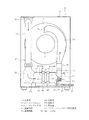
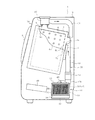
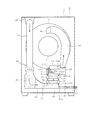
第1実施形態について図1から図7を参照して説明する。まず、図1および図2において、洗濯乾燥機1は、衣類の洗濯機能と乾燥機能を備えたドラム式のものであり、衣類乾燥機としても機能する。洗濯乾燥機1の本体を構成する外箱2は、ほぼ矩形の箱状をなしていて、前面部2a(図2の左側の面)がやや前下がりの傾斜状に形成されている。その前面部2aには、図示はしないが洗濯物出入口が形成されているとともに、当該洗濯物出入口を開閉する扉3が回動可能に設けられている。
Hereinafter, the clothes dryer by several embodiment is demonstrated based on drawing. In addition, in each embodiment, the same code | symbol is attached | subjected to the same structural part practically, and description is abbreviate | omitted.
(First embodiment)
A first embodiment will be described with reference to FIGS. First, in FIG. 1 and FIG. 2, the washing / drying machine 1 is a drum type having a washing function and a drying function for clothes, and also functions as a clothes dryer. The
外箱2内には、水槽4が図示しないサスペンションを介して弾性的に支持された状態で配設されている。この水槽4は、前面が開口し後面が閉塞された有底円筒状をなしていて、軸線方向を前後方向に指向させ、かつやや前上がりの傾斜状態に配置されている。水槽4の前面開口部は、蛇腹状のべローズ(図示せず)を介して前記洗濯物出入口に接続されている。水槽4は、洗濯物(衣類)を乾燥させる乾燥運転時には乾燥室として機能する。
A water tank 4 is disposed in the
水槽4内にはドラム6が回転可能に配設されている。このドラム6も、水槽4と同様に、前面に開口部を有し後面が閉塞された有底円筒状をなしていて、軸線方向を前後方向に指向させ、かつやや前上がりの傾斜状態に配置されている。ドラム6の周壁部および後壁部には多数の孔6aが形成されている。これらの孔6aは、洗濯時には水が通る通水孔として機能し、乾燥時には乾燥風が通る通風孔として機能する。水槽4の背部にはモータ7が設けられていて、ドラム6は、そのモータ7により回転軸7aを介して回転駆動される構成となっている。なお、ドラム6の周壁部の内部には、図示はしないが複数のバッフルが設けられている。衣類を含む洗濯物は、洗濯物出入口、水槽4の開口部、およびドラム6の開口部を通してドラム6内に出し入れ可能に収容される。
A
次に、水槽4に接続される循環風路と、ドラム6内に収容された洗濯物(衣類)を乾燥させる乾燥手段について、図3も参照して説明する。水槽4には、後部壁に風入口8aが設けられているとともに、周壁部の前部の上部に上向きの風出口8bが設けられている。風出口8bの上部には、振動吸収用の蛇腹状の接続ダクト9を介してフィルタケース10が接続されている。フィルタケース10内には、図示はしないがリントフィルタが着脱可能に設けられている。
Next, the circulation air path connected to the water tank 4 and the drying means for drying the laundry (clothing) accommodated in the
フィルタケース10の後部には、排気ダクト11の前端部が接続されている。排気ダクト11は、後方へ向けて延びた後、下方に向きを変え、その下端部が、外箱2内の下部でかつ水槽4の下方に設けられたヒートポンプユニット12のヒートポンプ用ダクト13の一端部に接続されている。ヒートポンプ用ダクト13は横方向に延び、その他端部は、送風手段を構成する送風機14におけるファンケーシング15の吸入口15aに接続されている。送風機14は、ファンケーシング15と、このファンケーシング15内に配設されたファン16と、このファン16を回転駆動するファンモータ17により構成されている。ファンケーシング15の吐出口15bは上向きに設けられていて、この吐出口15bに、振動吸収用の蛇腹状の接続ダクト18を介して給気ダクト19の一端部が接続されている。給気ダクト19の他端部は上方へ延びていて、水槽4の後部の前記風入口8aに接続されている。
A front end portion of the
ここで、水槽4の風出口8bに接続された接続ダクト9、フィルタケース10、排気ダクト11、ヒートポンプ用ダクト13、送風機14のファンケーシング15、接続ダクト18、および給気ダクト19により循環風路20を構成している。この循環風路20は、水槽4の外側でかつ外箱2内において、一端部が風入口8aに接続され他端部が風出口8bに接続されている。
Here, a circulation air path is formed by the connection duct 9, the
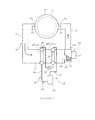
前記ヒートポンプユニット12におけるヒートポンプ21は、図3に示すように、圧縮機22、凝縮器23、絞り装置24、蒸発器25を配管26によりサイクル接続して冷凍サイクルを構成する。このうち、熱交換器を構成する凝縮器23と蒸発器25が、循環風路20におけるヒートポンプ用ダクト13内に配置されている。ヒートポンプ用ダクト13において、凝縮器23は送風機14寄りに配置され、蒸発器25は排気ダクト11寄りに配置されている。凝縮器23は、循環風路20を通る空気を加熱する加熱手段として機能し、蒸発器25は、循環風路20内を通る空気を冷却して除湿する除湿手段として機能する。
As shown in FIG. 3, the
図3に示すように、ヒートポンプ21において、圧縮機22の吐出口付近と、凝縮器23と、蒸発器25の入口付近と、圧縮機22の入口付近には、それぞれ温度センサ27,28,29,30が設けられている。また、循環風路20において、風入口8a付近と風出口8b付近にもそれぞれ温度センサ31,32が設けられている。乾燥運転時にこれら温度センサ27〜32の検出温度に基づき圧縮機22の運転が制御される。
As shown in FIG. 3, in the
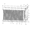
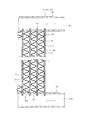
ここで、凝縮器23および蒸発器25は、コルゲートフィンタイプの熱交換器34を用いている。コルゲートフィンタイプの熱交換器34は、図4および図5にも示すように、上下両側に配置された第1のヘッダ部35および第2のヘッダ部36と、これら第1のヘッダ部35および第2のヘッダ部36間にこれらを連結するように設けられた多数枚のプレート37と、隣り合った各プレート37間に設けられた波板状のコルゲートフィン38を備えている。
Here, the
第1のヘッダ部35および第2のヘッダ部36は、それぞれ円筒状のパイプ状をなしていて、所定距離離間して平行状態に配置されている。これら第1のヘッダ部35および第2のヘッダ部36は内部に冷媒通路35a,36aを有していて、それぞれの冷媒通路35a,36bの一端部は、閉塞部35b,36bにて閉塞されている。第1のヘッダ部35の外周部には、対向する位置に位置させて一対の突条部39が設けられている。各突条部39は、第1のヘッダ部35の延び方向に沿って延びている。また、第2のヘッダ部36の外周部にも、第1のヘッダ部35と同様に、一対の突条部39が設けられている。
The
第1のヘッダ部35と第2のヘッダ部36間を連結する各プレート37は、上下方向に長い長方形の板状をなしていて、図5および図6に示すように上端部が第1のヘッダ部35の冷媒通路35a内に突出し、下端部が第2のヘッダ部36の冷媒通路36a内に突出している。各プレート37は、側面が第1および第2のヘッダ部35,36の延び方向に対して直交するように配置されている。各プレート37の内部には、上下方向に延びる分流通路40(図5参照)が複数本設けられている。各分流通路40は、上端部が第1のヘッダ部35の冷媒通路35aに連通し、下端部が第2のヘッダ部36の冷媒通路36aに連通している。
Each
隣り合った各プレート37間には、波板状のコルゲートフィン38が設けられていて、このコルゲートフィン38により通気部38aが形成されている。各通気部38aは、第1および第2のヘッダ部35,36の延び方向に対して直交する横方向に延びていて、両端部が開口している。
このような構成のコルゲートフィンタイプの熱交換器34において、第1のヘッダ部35の冷媒通路35aと第2のヘッダ部36の冷媒通路36aは前記配管26に接続される。第1のヘッダ部35の冷媒通路35aに冷媒が供給されると、その冷媒は、各プレート37の各分流通路40に分かれてここを通り、第2のヘッダ部36の冷媒通路36a側へ流れ、その冷媒通路36aの冷媒は配管26側へ流れる。このとき、各分流通路40を流れる冷媒は、波板状のコルゲートフィン38の周りの通気部38aを通る空気と熱交換することになる。
In the corrugated fin
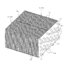
図6には、上記熱交換器34を、ヒートポンプ用ダクト13に固定する構造の一例が示されている。ヒートポンプ用ダクト13は、上ダクト13aと下ダクト13bを組み合わせて構成されていて、これら上ダクト13aおよび下ダクト13bのそれぞれのフランジ部41同士を重ね合わせた状態でねじ42により連結している。各熱交換器34は、ヒートポンプ用ダクト13内に位置させた状態で、第1および第2の各ヘッダ部35,36の外周部を、上ダクト13aおよび下ダクト13bに形成された各開口部43に挿入し、各突条部39を開口部43の周縁部に内側から宛がった状態で、ヒートポンプ用ダクト13内に固定状態に設けられている。また、各熱交換器34は、ヒートポンプ用ダクト13内を流れる空気がそれぞれの通気部38aを通るように、通気部38aを横向きにした状態で配設されている。
FIG. 6 shows an example of a structure for fixing the
したがってこの場合、コルゲートフィンタイプの熱交換器34を用いて構成された凝縮器23および蒸発器25は、循環風路20の一部を構成するヒートポンプ用ダクト13への固定に第1および第2のヘッダ部35,36を利用している。また、ヒートポンプ21は、コルゲートフィンタイプの熱交換器34を用いて構成された凝縮器23および蒸発器25を、循環風路20の一部を構成するヒートポンプ用ダクト13内に収納するとともに、圧縮機22および絞り装置24をヒートポンプ用ダクト13の周辺に設置することで、ヒートポンプユニット12としてユニット化している。
Therefore, in this case, the
図1に示すようにヒートポンプ用ダクト13の下部には、蒸発器25および凝縮器23の下方に位置させてドレンタンク45が設けられている。乾燥運転時にヒートポンプ用ダクト13内を流れる湿気を含んだ空気が蒸発器25において冷却されると、その冷却により生じた結露水が、このドレンタンク45に受けられて貯留される。湿気を含んだ空気は、蒸発器25を通過することで、湿気が除去される。ドレンタンク45に貯留された結露水(除湿水)は、ドレンポンプ46および排水ホース47を介して機外へ排出される。蒸発器25の上部には、振動発生用の振動モータ48が設けられている。この振動モータ48により蒸発器25を振動させることで、当該蒸発器25のプレート37やコルゲートフィン38に付着した結露水が下方へ落ちやすくなり、ドレンタンク45に溜まりやすくなる。
As shown in FIG. 1, a
なお、図示はしないが、外箱2の前面部2aの上部には操作パネルが設けられている。また、洗濯乾燥機1には、これも図示はしないが、洗濯運転時に使用する水を水槽4内へ供給する給水手段や、水槽4内の水を機外へ排出するための排水手段などが設けられている。図2に示すように、外箱2内の下部には制御装置49が設けられている。制御装置49は、マイクロコンピュータを主体に構成されていて、操作パネルの設定内容と、予め備えた制御プログラムに基づき、前記モータ7、ヒートポンプ21、送風機14、ドレンポンプ46、振動モータ48、前記給水手段や排水手段などを制御する。
Although not shown, an operation panel is provided on the upper portion of the
上記構成において、ドラム6内に収容された衣類を乾燥させる乾燥運転時には、扉3が閉鎖された状態で、ドラム6が適宜回転されるとともに、ヒートポンプ21の圧縮機22が駆動され、さらに送風機14が駆動される。
In the above configuration, during the drying operation for drying the clothes accommodated in the
このうち、ドラム6が回転されることに伴い、ドラム6内に収容された衣類が撹拌される。また、圧縮機22が駆動されることに伴い、圧縮機22において冷媒が圧縮され、高温高圧のガス冷媒が凝縮器23に向けて吐出される。凝縮器23においては、高温高圧のガス冷媒が放熱して凝縮する。この後、絞り装置24で高圧の冷媒が減圧された後、蒸発器25で冷媒が蒸発することで吸熱する。蒸発してガス化した冷媒は再び圧縮機22に戻り圧縮される、ということを繰り返す。
Among these, the clothes accommodated in the
そして、送風機14が駆動されることに伴い、循環風路20におけるヒートポンプ用ダクト13内において凝縮器23で加熱された空気がファンケーシング15内に吸入されるとともに、その空気が吐出口15bから温風となって吐出される。その温風は、給気ダクト19を通り、風入口8aから水槽4内へ供給される。水槽4内へ供給された温風は、ドラム6の孔6aを通してドラム6内にも供給される。ドラム6内に供給された温風は、衣類と接触して当該衣類を温めるとともに、当該衣類から湿気を奪う。湿気を含んだ空気は、風出口8bから循環風路20側へ排出される。その空気は、フィルタケース10を通り、排気ダクト11側へ排出される。排気ダクト11を流れた空気は、下方のヒートポンプ用ダクト13内に入り、蒸発器25により冷却されて除湿される。除湿された空気は、再び凝縮器23で加熱され温風となって水槽4内に供給されるということを繰り返す。これに伴い、ドラム6内の衣類は次第に乾燥される。
As the
このとき、水槽4内の空気が循環風路20を通して循環される際に、衣類から出たリント(糸屑)があると、そのリントはフィルタケース10内のリントフィルタにて捕獲される。また、蒸発器25により冷却されることで発生した結露水(除湿水)は、前述したようにドレンタンク45内に貯留される。ドレンタンク45内に貯留された結露水は、ドレンポンプ46により適宜機外へ排出される。
At this time, when the air in the water tank 4 is circulated through the
上記した実施形態によれば、次のような作用効果を得ることができる。
洗濯乾燥機1において、乾燥手段として機能するヒートポンプ21の凝縮器23および蒸発器25にコルゲートフィンタイプの熱交換器34を用いた。コルゲートフィンタイプの熱交換器34は、冷媒と空気との熱交換効率が高く、従来用いられているフィンチューブタイプの熱交換器よりも小型化が可能となる。これに伴い、ヒートポンプ21の凝縮器23および蒸発器25を小型化できることにより、ヒートポンプ用ダクト13の小型化が可能となり、ヒートポンプ21、ヒートポンプユニット14の小型化が可能となる。
According to the above-described embodiment, the following operational effects can be obtained.
In the washing / drying machine 1, a corrugated fin
図7には、従来の洗濯乾燥機に用いられているフィンチューブタイプの熱交換器51の一例が示されている。この場合、二つの熱交換器51が端板52により連結された形態となっていて、一方の熱交換器51は凝縮器53に用いられ、他方の熱交換器51は蒸発器54に用いられる。各熱交換器51は、蛇行状に配置される冷媒パイプ55と、平板状をなす多数枚のフィン56と、両端部に配置された端板52を備えていて、冷媒パイプ55が、多数枚のフィン56および端板52を貫通した形態となっている。冷媒パイプ55の各折返し部55aは、端板52から外側へ突出している。
FIG. 7 shows an example of a fin tube
本実施形態において、コルゲートフィンタイプの熱交換器34は、第1のヘッダ部35および第2のヘッダ部36を備えていて、循環風路20を形成するヒートポンプ用ダクト13への固定にそれら第1のヘッダ部35および第2のヘッダ部36を利用している。これによれば、熱交換器34のヒートポンプ用ダクト13への固定が容易にできる。しかも、第1および第2のヘッダ部35,36が、循環風の流れを極力妨げないようにできる。
In this embodiment, the corrugated fin-
ヒートポンプ21は、コルゲートフィンタイプの熱交換器34を用いて構成された凝縮器23および蒸発器25を、循環風路20の一部を構成するヒートポンプ用ダクト13内に収納するとともに、圧縮機22および絞り装置24をヒートポンプ用ダクト13の周辺に設置することで、ヒートポンプユニット12としてユニット化している。これによれば、ヒートポンプ21の取り扱い性および組立性の向上を図ることが可能となる。
The
コルゲートフィンタイプの熱交換器34を用いた蒸発器25に振動モータ48を設け、その振動モータ48により蒸発器25を振動させることで、蒸発器25におけるプレート37やコルゲートフィン38に付着した結露水を落ちやすくできる利点がある。プレート37やコルゲートフィン38に付着した結露水が落ち難い場合には、その結露水が、プレート37間の通気部38aを通過する風の抵抗となり、風量が低下するおそれがあるが、本実施形態においてはそのような不具合を極力解消することが可能となる。
The
(第2実施形態)
図8は第2実施形態を示している。この第2実施形態は、上記した第1実施形態とは次の点が異なっている。すなわち、ヒートポンプ用ダクト13内に配設される2つの熱交換器のうち凝縮器23は、第1実施形態と同様のコルゲートフィンタイプの熱交換器34を用いているが、蒸発器60はフィンチューブタイプの熱交換器51(図7参照)を用いている。
(Second Embodiment)
FIG. 8 shows a second embodiment. The second embodiment is different from the first embodiment described above in the following points. That is, among the two heat exchangers disposed in the
この実施形態によれば、ヒートポンプ用ダクト13内に配設される2つの熱交換器のうち凝縮器23はコルゲートフィンタイプの熱交換器34を用いているので、少なくとも凝縮器23の小型化が可能となり、その分ヒートポンプユニット12の小型化が可能となる。蒸発器60で用いたフィンチューブタイプの熱交換器51は、フィン56に付着した結露水は板状のフィン56に沿って比較的落下しやすいため、振動モータ48を設けなくてもよいが、設ければ一層落下させやすくできる。
According to this embodiment, since the
(第3実施形態)
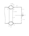
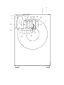
図9は第3実施形態を示している。この第3実施形態は、上記した第1実施形態とは次の点が異なっている。すなわち、循環風路20のヒートポンプ用ダクト61において、図9の右側は上に向けられていて、この上向き部61aに、凝縮器23と蒸発器25が上下に並べて配設されている。凝縮器23および蒸発器25は、ともにコルゲートフィンタイプの熱交換器34が用いられていて、蒸発器25が凝縮器23の下側に配置されている。凝縮器23および蒸発器25は、それぞれの通気部38aが上下方向を向くように配置されている。
(Third embodiment)
FIG. 9 shows a third embodiment. The third embodiment differs from the first embodiment described above in the following points. That is, in the
ヒートポンプ用ダクト61の上向き部61aの上端部が、送風機14におけるファンケーシング15の吸入口15aに接続されている。送風機14は、上向き部61aの上部に配設され、ファンケーシング15の吐出口15bに、接続ダクト18を介して給気ダクト19の一端部が接続されている。
The upper end portion of the
上記した実施形態において、乾燥運転時には、排気ダクト11を通った空気は、矢印で示すように、ヒートポンプ用ダクト61を横方向に流れた後、上向き部61aでは下から上に向けて流れる。このとき、その上向きに流れる空気は、蒸発器25および凝縮器23のそれぞれの通気部38aを下から上に向けて流れ、それぞれの熱交換器34と熱交換する。
In the above-described embodiment, during the drying operation, the air passing through the
上記した実施形態においては、蒸発器25を凝縮器23よりも下側に配置しているので、蒸発器25において結露した結露水は、凝縮器23に接触することなく、ドレンタンク45に落下させることが可能になる。しかもこの場合、蒸発器25における通気部38a(図5参照)は上下方向を向いているので、プレート37やコルゲートフィン38に付着した結露水はそれらに沿って下方へ落ちやすくなる。このため、蒸発器25には、振動モータ48を設けなくてもよいが、設ければ一層落下しやすくできる。
In the above-described embodiment, the
(第4実施形態)
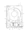
図10および図11は第4実施形態を示している。この第4実施形態は、上記した第1実施形態とは次の点が異なっている。すなわち、循環風路20におけるヒートポンプ用ダクト13およびドレンタンク45の位置が、第1実施形態の場合よりも高い位置に設けられている。そして、図11に示すように、ドレンタンク45の底部45aが前下がりの傾斜状に形成されているとともに、ドレンタンク45の前部にドレンタンク用導水路63が設けられている。水槽4の底部には排水弁64を備えた排水路65が設けられていて、この排水路65が排水管66に接続されている。そして、前記ドレンタンク用導水路63の先端部が排水管66に接続されている。
(Fourth embodiment)
10 and 11 show a fourth embodiment. The fourth embodiment is different from the above-described first embodiment in the following points. That is, the positions of the
この場合、排水弁64が開放されることに伴い、水槽4内の水が排水路65および排水管66を通して機外へ排出される。また、ドレンタンク45にて受けた結露水は、ドレンタンク用導水路63および排水管66を通して機外へ排出される。
In this case, as the
この実施形態によれば、排水管66は、水槽4の排水と、ドレンタンク45の排水とに共用できる。また、ヒートポンプ用ダクト13およびドレンタンク45の位置を高く設定し、ドレンタンク45の水を、傾斜を利用して排水管66に流す構成としたことにより、強制的に排水するドレンポンプ46を不要にすることが可能となる。
According to this embodiment, the
(第5実施形態)
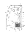
図12は第5実施形態を示している。この第5実施形態は、上記した第1実施形態とは次の点が異なっている。すなわち、ヒートポンプユニット12を、洗濯乾燥機1の本体を構成する外箱2内の後部の上部に位置させている。これに伴い、ヒートポンプ用ダクト13が外箱2内の後部の上部に配置され、排気ダクト11は下方への長さが短く設定されている。また、送風機14におけるファンケーシング15の吐出口は後方に向けられ、水槽4の後部の風入口8aに接続されている。
(Fifth embodiment)
FIG. 12 shows a fifth embodiment. The fifth embodiment differs from the first embodiment described above in the following points. That is, the
この実施形態によれば、循環風路20の長さを極力短くできるとともに、ヒートポンプユニット12を一層コンパク化することが可能になる。また、加熱手段として機能する凝縮器23を、水槽4の風入口8aの近傍に配置した構成となるので、凝縮器23で加熱した温風を、極力温度低下させない状態で水槽4内へ供給することが可能となる利点がある。さらには、ドレンタンク45の位置も高くなるので、ドレンタンク45内に貯留される結露水を、重力を利用することで、直接排水ホース47を介して機外へ排出することが可能となり、ドレンポンプ46を不要にすることも可能となる。
According to this embodiment, the length of the
(その他の実施形態)
水槽および回転槽の軸方向が上下方向に指向する、いわゆる縦型の洗濯乾燥機に適用することも可能である。また、洗濯機能のないものにも適用できる。
(Other embodiments)
The present invention can also be applied to a so-called vertical washer / dryer in which the axial direction of the water tank and the rotating tank is oriented in the vertical direction. It can also be applied to those without a washing function.
以上説明したように本実施形態によれば、凝縮器および蒸発器のうちの少なくとも一方にコルゲートフィンタイプの熱交換器を用いることで、ヒートポンプの小型化に寄与することが可能となる。 As described above, according to the present embodiment, it is possible to contribute to downsizing of the heat pump by using a corrugated fin type heat exchanger for at least one of the condenser and the evaporator.
本発明のいくつかの実施形態を説明したが、これらの実施形態は、例として提示したものであり、例えばヘッダ部35,36の突条部39とダクト13との当接部に空気漏れを防ぐようパッキン(図示せず)を設けるなど、発明の範囲を限定することは意図していない。これら新規な実施形態は、その他の様々な形態で実施されることが可能であり、発明の要旨を逸脱しない範囲で、種々の省略、置き換え、変更を行うことができる。これら実施形態やその変形は、発明の範囲や要旨に含まれるとともに、特許請求の範囲に記載された発明とその均等の範囲に含まれる。
Although several embodiments of the present invention have been described, these embodiments are presented as examples. For example, air leakage is caused in the contact portion between the
図面中、1は洗濯乾燥機(衣類乾燥機)、2は外箱(本体)、4は水槽(乾燥室)、6はドラム、8aは風入口、8bは風出口、12はヒートポンプユニット、13はヒートポンプ用ダクト、14は送風機(送風手段)、20は循環風路、21はヒートポンプ、22は圧縮機、23は凝縮器、24は絞り装置、25は蒸発器、26は配管、34はコルゲートフィンタイプの熱交換器、35は第1のヘッダ部、36は第2のヘッダ部、37はプレート、38はコルゲートフィン、39は突条部、45はドレンタンク、46はドレンポンプ、48は振動モータ、49は制御装置、51はフィンチューブタイプの熱交換器、60は蒸発器、61はヒートポンプ用ダクト、61aは上向き部、63はドレンタンク用導水路、66は排水管を示す。 In the drawings, 1 is a washing dryer (clothing dryer), 2 is an outer box (main body), 4 is a water tank (drying chamber), 6 is a drum, 8a is an air inlet, 8b is an air outlet, 12 is a heat pump unit, 13 Is a heat pump duct, 14 is a blower (air blowing means), 20 is a circulation air passage, 21 is a heat pump, 22 is a compressor, 23 is a condenser, 24 is a condensing device, 25 is an evaporator, 26 is a pipe, and 34 is a corrugate Fin type heat exchanger, 35 is a first header part, 36 is a second header part, 37 is a plate, 38 is a corrugated fin, 39 is a ridge part, 45 is a drain tank, 46 is a drain pump, 48 is A vibration motor, 49 is a control device, 51 is a fin tube type heat exchanger, 60 is an evaporator, 61 is a heat pump duct, 61a is an upward portion, 63 is a water conduit for a drain tank, and 66 is a drain pipe.
Claims (8)
この乾燥室の外側において両端部が当該乾燥室内と連通するように設けられた循環風路と、
前記乾燥室内の空気を前記循環風路を通して循環させる送風手段と、
圧縮機、凝縮器、絞り装置、蒸発器を順に接続して冷凍サイクルを構成し、このうち前記凝縮器および蒸発器を前記循環風路中に配設して構成されるヒートポンプと、を備え、
前記凝縮器および蒸発器のうち少なくとも一方にコルゲートフィンタイプの熱交換器を用いた衣類乾燥機。 A drying chamber for storing clothes to be dried;
A circulation air passage provided so that both ends communicate with the drying chamber outside the drying chamber;
Air blowing means for circulating the air in the drying chamber through the circulation air passage;
A compressor, a condenser, an expansion device, and an evaporator are connected in order to constitute a refrigeration cycle, and among these, a heat pump configured by disposing the condenser and the evaporator in the circulation air path, and
A clothes dryer using a corrugated fin type heat exchanger for at least one of the condenser and the evaporator.
Priority Applications (2)
| Application Number | Priority Date | Filing Date | Title |
|---|---|---|---|
| JP2015014265A JP6545967B2 (en) | 2015-01-28 | 2015-01-28 | Clothes dryer |
| CN201510982023.1A CN105821632B (en) | 2015-01-28 | 2015-12-23 | Clothesdrier |
Applications Claiming Priority (1)
| Application Number | Priority Date | Filing Date | Title |
|---|---|---|---|
| JP2015014265A JP6545967B2 (en) | 2015-01-28 | 2015-01-28 | Clothes dryer |
Publications (2)
| Publication Number | Publication Date |
|---|---|
| JP2016137125A true JP2016137125A (en) | 2016-08-04 |
| JP6545967B2 JP6545967B2 (en) | 2019-07-17 |
Family
ID=56558668
Family Applications (1)
| Application Number | Title | Priority Date | Filing Date |
|---|---|---|---|
| JP2015014265A Active JP6545967B2 (en) | 2015-01-28 | 2015-01-28 | Clothes dryer |
Country Status (1)
| Country | Link |
|---|---|
| JP (1) | JP6545967B2 (en) |
Cited By (4)
| Publication number | Priority date | Publication date | Assignee | Title |
|---|---|---|---|---|
| JP2018108306A (en) * | 2017-01-05 | 2018-07-12 | 東芝ライフスタイル株式会社 | Clothes dryer |
| JP2018175444A (en) * | 2017-04-13 | 2018-11-15 | 東芝ライフスタイル株式会社 | Clothes dryer |
| KR20200137504A (en) * | 2019-05-30 | 2020-12-09 | 엘지전자 주식회사 | Laundry Treating Apparatus and Control Method for Laundry Treating Apparatus |
| WO2026026173A1 (en) * | 2024-07-31 | 2026-02-05 | 佛山市顺德区美的洗涤电器制造有限公司 | Air duct housing, heat pump drying system and washing appliance |
Citations (7)
| Publication number | Priority date | Publication date | Assignee | Title |
|---|---|---|---|---|
| JP2004053045A (en) * | 2002-07-16 | 2004-02-19 | Nikkei Nekko Kk | Duplex heat exchange arrangement |
| JP2004116899A (en) * | 2002-09-26 | 2004-04-15 | Matsushita Electric Ind Co Ltd | Heat pump dryer |
| JP2006110394A (en) * | 2006-01-26 | 2006-04-27 | Matsushita Electric Ind Co Ltd | Washing and drying machine |
| JP2009006126A (en) * | 2007-05-31 | 2009-01-15 | Panasonic Corp | Clothes dryer |
| JP2011085381A (en) * | 2009-10-15 | 2011-04-28 | Keihin Corp | Heat exchanger for use in air conditioner for vehicle |
| JP2012179266A (en) * | 2011-03-02 | 2012-09-20 | Hitachi Appliances Inc | Washing/drying machine |
| JP2014214903A (en) * | 2013-04-23 | 2014-11-17 | 株式会社ケーヒン・サーマル・テクノロジー | Evaporator and vehicle air conditioner using the same |
-
2015
- 2015-01-28 JP JP2015014265A patent/JP6545967B2/en active Active
Patent Citations (7)
| Publication number | Priority date | Publication date | Assignee | Title |
|---|---|---|---|---|
| JP2004053045A (en) * | 2002-07-16 | 2004-02-19 | Nikkei Nekko Kk | Duplex heat exchange arrangement |
| JP2004116899A (en) * | 2002-09-26 | 2004-04-15 | Matsushita Electric Ind Co Ltd | Heat pump dryer |
| JP2006110394A (en) * | 2006-01-26 | 2006-04-27 | Matsushita Electric Ind Co Ltd | Washing and drying machine |
| JP2009006126A (en) * | 2007-05-31 | 2009-01-15 | Panasonic Corp | Clothes dryer |
| JP2011085381A (en) * | 2009-10-15 | 2011-04-28 | Keihin Corp | Heat exchanger for use in air conditioner for vehicle |
| JP2012179266A (en) * | 2011-03-02 | 2012-09-20 | Hitachi Appliances Inc | Washing/drying machine |
| JP2014214903A (en) * | 2013-04-23 | 2014-11-17 | 株式会社ケーヒン・サーマル・テクノロジー | Evaporator and vehicle air conditioner using the same |
Cited By (6)
| Publication number | Priority date | Publication date | Assignee | Title |
|---|---|---|---|---|
| JP2018108306A (en) * | 2017-01-05 | 2018-07-12 | 東芝ライフスタイル株式会社 | Clothes dryer |
| JP2018175444A (en) * | 2017-04-13 | 2018-11-15 | 東芝ライフスタイル株式会社 | Clothes dryer |
| JP7164287B2 (en) | 2017-04-13 | 2022-11-01 | 東芝ライフスタイル株式会社 | clothes dryer |
| KR20200137504A (en) * | 2019-05-30 | 2020-12-09 | 엘지전자 주식회사 | Laundry Treating Apparatus and Control Method for Laundry Treating Apparatus |
| KR102737001B1 (en) * | 2019-05-30 | 2024-12-02 | 엘지전자 주식회사 | Laundry Treating Apparatus and Control Method for Laundry Treating Apparatus |
| WO2026026173A1 (en) * | 2024-07-31 | 2026-02-05 | 佛山市顺德区美的洗涤电器制造有限公司 | Air duct housing, heat pump drying system and washing appliance |
Also Published As
| Publication number | Publication date |
|---|---|
| JP6545967B2 (en) | 2019-07-17 |
Similar Documents
| Publication | Publication Date | Title |
|---|---|---|
| CN101016686B (en) | washing and drying machine | |
| CN201071469Y (en) | clothes dryer | |
| JP6616594B2 (en) | Clothes dryer | |
| CN105821632A (en) | Clothes dryer | |
| KR20210080039A (en) | Clothes dryer | |
| JP6545967B2 (en) | Clothes dryer | |
| JP2008048810A (en) | Clothes dryer | |
| JP3920299B2 (en) | Clothes dryer | |
| JP5121659B2 (en) | Washing and drying machine | |
| JP4602109B2 (en) | Dryer | |
| JP7319028B2 (en) | clothes dryer | |
| JP6850132B2 (en) | Clothes dryer | |
| JP6923620B2 (en) | Clothes dryer | |
| JP2009291226A (en) | Drying equipment | |
| JP4352803B2 (en) | Washing and drying machine | |
| JP4728834B2 (en) | Washing and drying machine | |
| JP2011244924A (en) | Clothes dryer | |
| JP5602802B2 (en) | Drying equipment | |
| JP2020039964A (en) | Washing and drying machine | |
| CN112941856A (en) | Clothes dryer | |
| WO2016047196A1 (en) | Dryer | |
| JP6175654B2 (en) | Drying equipment | |
| JP5873979B2 (en) | Drying equipment | |
| JP2009125208A (en) | Washing and drying machine | |
| JP5012225B2 (en) | Clothes dryer |
Legal Events
| Date | Code | Title | Description |
|---|---|---|---|
| A711 | Notification of change in applicant |
Free format text: JAPANESE INTERMEDIATE CODE: A711 Effective date: 20160627 |
|
| A621 | Written request for application examination |
Free format text: JAPANESE INTERMEDIATE CODE: A621 Effective date: 20171107 |
|
| A977 | Report on retrieval |
Free format text: JAPANESE INTERMEDIATE CODE: A971007 Effective date: 20180928 |
|
| A131 | Notification of reasons for refusal |
Free format text: JAPANESE INTERMEDIATE CODE: A131 Effective date: 20181016 |
|
| A521 | Request for written amendment filed |
Free format text: JAPANESE INTERMEDIATE CODE: A523 Effective date: 20181207 |
|
| TRDD | Decision of grant or rejection written | ||
| A01 | Written decision to grant a patent or to grant a registration (utility model) |
Free format text: JAPANESE INTERMEDIATE CODE: A01 Effective date: 20190521 |
|
| A61 | First payment of annual fees (during grant procedure) |
Free format text: JAPANESE INTERMEDIATE CODE: A61 Effective date: 20190620 |
|
| R150 | Certificate of patent or registration of utility model |
Ref document number: 6545967 Country of ref document: JP Free format text: JAPANESE INTERMEDIATE CODE: R150 |
|
| S531 | Written request for registration of change of domicile |
Free format text: JAPANESE INTERMEDIATE CODE: R313531 |
|
| R350 | Written notification of registration of transfer |
Free format text: JAPANESE INTERMEDIATE CODE: R350 |
|
| S111 | Request for change of ownership or part of ownership |
Free format text: JAPANESE INTERMEDIATE CODE: R313113 |
|
| R371 | Transfer withdrawn |
Free format text: JAPANESE INTERMEDIATE CODE: R371 |
|
| S111 | Request for change of ownership or part of ownership |
Free format text: JAPANESE INTERMEDIATE CODE: R313113 |