JP2020039964A - Washing and drying machine - Google Patents

Washing and drying machine Download PDF

Info

Publication number
JP2020039964A
JP2020039964A JP2019229126A JP2019229126A JP2020039964A JP 2020039964 A JP2020039964 A JP 2020039964A JP 2019229126 A JP2019229126 A JP 2019229126A JP 2019229126 A JP2019229126 A JP 2019229126A JP 2020039964 A JP2020039964 A JP 2020039964A
Authority
JP
Japan
Prior art keywords
evaporator
condenser
refrigerant
inflow
air
Prior art date
Legal status (The legal status is an assumption and is not a legal conclusion. Google has not performed a legal analysis and makes no representation as to the accuracy of the status listed.)
Pending
Application number
JP2019229126A
Other languages
Japanese (ja)
Inventor
田中 俊行
Toshiyuki Tanaka
俊行 田中
佐久間 勉
Tsutomu Sakuma
勉 佐久間
Current Assignee (The listed assignees may be inaccurate. Google has not performed a legal analysis and makes no representation or warranty as to the accuracy of the list.)
Toshiba Lifestyle Products and Services Corp
Original Assignee
Toshiba Lifestyle Products and Services Corp
Priority date (The priority date is an assumption and is not a legal conclusion. Google has not performed a legal analysis and makes no representation as to the accuracy of the date listed.)
Filing date
Publication date
Application filed by Toshiba Lifestyle Products and Services Corp filed Critical Toshiba Lifestyle Products and Services Corp
Priority to JP2019229126A priority Critical patent/JP2020039964A/en
Publication of JP2020039964A publication Critical patent/JP2020039964A/en
Pending legal-status Critical Current

Links

Images

Abstract

To improve heat exchange efficiency of a heat exchanger without increasing the size of the heat exchanger.SOLUTION: A washing and drying machine can execute a washing operation and a drying operation and it includes: a water tub having an exhaust port and an air supply port; a rotary tub stored in the water tub; a drain part located below the exhaust port and the air supply port, and for draining water in the water tub; a circulation air passage provided outside of the water tub, and for connecting the exhaust port and the air supply port; two or more parallel flow type evaporators connected in parallel, and for dehumidifying the air in the circulation air passage; and two or more parallel flow type condensers connected in parallel, and for heating the air in the circulation air passage. The evaporator includes: an inflow port for evaporator for allowing a refrigerant to flow in the evaporator; and an outflow port for evaporator provided further upward than the evaporator inflow port and for allowing the refrigerant in the evaporator to flow out of the evaporator. The condenser includes: an inflow port for condenser for allowing the refrigerant to flow in the condenser; and an outflow port for condenser provided further downward than the condenser inflow port, and for allowing the refrigerant in the condenser to flow out of the condenser.SELECTED DRAWING: Figure 7

Description

本発明の実施形態は、洗濯乾燥機に関する。   Embodiments of the present invention relate to a washer / dryer.

近年、乾燥用の温風の加熱方式にヒートポンプ方式を採用した衣類乾燥機が増えている。ヒートポンプ方式の乾燥機は、ヒータ方式に比べて低温度で乾燥が行えることから熱による衣類等の傷みが少なく、また、消費電力も少なく省エネであるという利点を有している。ヒートポンプ方式の衣類乾燥機は、熱交換器としての蒸発器及び凝縮器を含むヒートポンプユニットを備えている。そして、従来、衣類乾燥機用のヒートポンプユニットには、部品コストが比較的安価である等の理由から、フィンチューブ方式の熱交換器が採用されていた。   In recent years, clothes dryers adopting a heat pump method as a heating method of hot air for drying are increasing. The heat pump type dryer has the advantages that it can be dried at a lower temperature than the heater type, so that the clothes and the like are not easily damaged by heat, the power consumption is small, and the energy is saved. The heat pump type clothes dryer includes a heat pump unit including an evaporator and a condenser as a heat exchanger. Conventionally, a heat pump unit for a clothes dryer employs a fin tube type heat exchanger because parts costs are relatively low.

フィンチューブ方式の熱交換器の場合、熱交換器を大型化して熱交換に寄与する面積を増やすことで、熱交換の効率を向上させることができる。しかし、衣類乾燥機の小型化や大容量化が望まれる昨今においては、熱交換効率を向上させるためとはいえ、熱交換器を大型化することは望ましくない。   In the case of the fin tube type heat exchanger, the heat exchange efficiency can be improved by increasing the size of the heat exchanger and increasing the area contributing to the heat exchange. However, in recent years, in which it is desired to reduce the size and capacity of the clothes dryer, it is not desirable to increase the size of the heat exchanger even though the heat exchange efficiency is improved.

特開2008−6069号公報JP 2008-6069 A

そこで、蒸発器及び凝縮器を大型化することなく、蒸発器及び凝縮器の熱交換効率を向上させることができる洗濯乾燥機を提供する。   Therefore, a washing / drying machine capable of improving the heat exchange efficiency of the evaporator and the condenser without increasing the size of the evaporator and the condenser is provided.

本実施形態の洗濯乾燥機は、洗濯運転と乾燥運転とを実行可能であって、排気口及び給気口を有する水槽と、前記水槽の内部に収容される回転槽と、前記排気口及び給気口の下方に位置して前記水槽内の水を排水する排水部と、前記水槽の外側に設けられ前記排気口と前記給気口とを繋ぐ循環風路と、前記循環風路内の空気を除湿するパラレルフロー方式の並列に接続された2つ以上の蒸発器と、前記循環風路内の空気を加熱するパラレルフロー方式の並列に接続された2つ以上の凝縮器と、を備える。前記蒸発器は、前記蒸発器内に冷媒を流入させる蒸発器用流入口と、前記蒸発器流入口よりも上方に設けられて前記蒸発器内の冷媒を前記蒸発器外に流出させる蒸発器用流出口と、を有する。前記凝縮器は、前記凝縮器内に冷媒を流入させる凝縮器用流入口と、前記凝縮器流入口よりも下方に設けられて前記凝縮器内の冷媒を前記凝縮器外に流出させる凝縮器用流出口と、を有する。   The washing / drying machine according to the present embodiment is capable of performing a washing operation and a drying operation, and has a water tub having an exhaust port and an air supply port, a rotating tub accommodated inside the water tub, the exhaust port and the water supply port. A drainage portion located below the air port for draining water in the water tank, a circulation air path provided outside the water tank and connecting the exhaust port and the air supply port, and air in the circulation air path. And two or more condensers connected in parallel in a parallel flow system for heating air in the circulating air passage, and two or more condensers connected in parallel in a parallel flow system for dehumidifying air. The evaporator has an evaporator inlet through which a refrigerant flows into the evaporator, and an evaporator outlet provided above the evaporator inlet to allow the refrigerant in the evaporator to flow out of the evaporator. And The condenser has a condenser inlet through which a refrigerant flows into the condenser, and a condenser outlet provided below the condenser inlet to allow the refrigerant in the condenser to flow out of the condenser. And

第1実施形態による洗濯乾燥機の概略構成の一例について一部を破断して示す側面図Side view showing a part of an example of a schematic configuration of a washing and drying machine according to a first embodiment in a partially broken manner. 第1実施形態による洗濯乾燥機の概略構成の一例について一部を破断して示す背面図Rear view partially broken away showing an example of a schematic configuration of a washing and drying machine according to a first embodiment. 第1実施形態について、ヒートポンプユニットを含む洗濯乾燥機の模式図FIG. 1 is a schematic view of a washing and drying machine including a heat pump unit according to a first embodiment. 第1実施形態について、蒸発器及び凝縮器の概略構成を示す外観斜視図External perspective view showing a schematic configuration of an evaporator and a condenser according to the first embodiment. 第1実施形態について、蒸発器の概略構成を示す断面図Sectional view showing a schematic configuration of an evaporator according to the first embodiment. 第1実施形態について、凝縮器の概略構成を示す断面図Sectional view showing a schematic configuration of a condenser according to the first embodiment. 第2実施形態について、ヒートポンプユニットを含む洗濯乾燥機の模式図FIG. 2 is a schematic diagram of a washing / drying machine including a heat pump unit according to a second embodiment. 第2実施形態について、蒸発器及び凝縮器の概略構成を示す外観斜視図External perspective view showing a schematic configuration of an evaporator and a condenser according to a second embodiment. 他の実施形態について、蒸発器及び凝縮器の概略構成を示す断面図(その1)Cross-sectional view showing a schematic configuration of an evaporator and a condenser according to another embodiment (part 1) 他の実施形態について、蒸発器及び凝縮器の概略構成を示す断面図(その2)Sectional drawing showing the schematic structure of an evaporator and a condenser about another embodiment (the 2)

以下、複数の実施形態による洗濯乾燥機について、図面を参照して説明する。なお、各実施形態において実質的に同一の構成部位には同一の符号を付し、説明を省略する。   Hereinafter, washing and drying machines according to a plurality of embodiments will be described with reference to the drawings. In each embodiment, substantially the same components are denoted by the same reference numerals, and description thereof will be omitted.

(第1実施形態)
まず、第1実施形態について、図1〜図6を参照して説明する。図1及び図2に示す洗濯乾燥機10は、外箱11、水槽12、回転槽13、モータ14、及び扉15(図2参照)を備えている。なお、本実施形態において、外箱11に対して扉15側を洗濯乾燥機10の前側とする。また、洗濯乾燥機10の設置面側つまり鉛直下側を、洗濯乾燥機10の下側とし、設置面と反対側つまり鉛直上側を、洗濯乾燥機10の上側とする。
(1st Embodiment)
First, a first embodiment will be described with reference to FIGS. The washing / drying machine 10 shown in FIGS. 1 and 2 includes an outer box 11, a water tub 12, a rotating tub 13, a motor 14, and a door 15 (see FIG. 2). In the present embodiment, the door 15 side with respect to the outer box 11 is the front side of the washer / dryer 10. Further, the installation surface side of the washing and drying machine 10, that is, the vertical lower side is defined as the lower side of the washing and drying machine 10, and the opposite side to the installation surface, that is, the vertical upper side is defined as the upper side of the washing and drying machine 10.

洗濯乾燥機10は、洗濯機能及びヒートポンプ方式の乾燥機能を備えており、回転槽13の回転軸が地面に対して傾斜したいわゆるドラム式の洗濯乾燥機である。外箱11は、鋼板などによって略矩形の箱状に形成されている。水槽12は、外箱11の内部に収容されている。回転槽13は、水槽12の内部に収容されている。水槽12及び回転槽13は、いずれも円筒状に形成されている。   The washing and drying machine 10 has a washing function and a drying function of a heat pump system, and is a so-called drum type washing and drying machine in which the rotation axis of the rotating tub 13 is inclined with respect to the ground. The outer box 11 is formed in a substantially rectangular box shape using a steel plate or the like. The water tank 12 is housed inside the outer box 11. The rotating tank 13 is housed inside the water tank 12. Both the water tank 12 and the rotary tank 13 are formed in a cylindrical shape.

図1に示すように、水槽12は、円筒状の一方の端部に開口部121が形成され、他方の端部に水槽端板122が設けられている。開口部121は、傾斜した水槽12において水槽端板122よりも上側に位置している。同様に、回転槽13は、円筒状の一方の端部に開口部131が形成され、他方の端部に回転槽端板132が設けられている。開口部131は、傾斜した回転槽13において回転槽端板132よりも上側に位置している。回転槽13の開口部131は、水槽12の開口部121に周囲を覆われている。水槽12及び回転槽13は、衣類等の乾燥対象物を収容する乾燥室として機能する。   As shown in FIG. 1, the water tank 12 has an opening 121 at one end of a cylindrical shape, and a water tank end plate 122 at the other end. The opening 121 is located above the water tank end plate 122 in the inclined water tank 12. Similarly, the rotating tank 13 has an opening 131 at one end of a cylindrical shape, and a rotating tank end plate 132 at the other end. The opening 131 is located above the rotating tank end plate 132 in the inclined rotating tank 13. The periphery of the opening 131 of the rotating tank 13 is covered by the opening 121 of the water tank 12. The water tub 12 and the rotary tub 13 function as a drying chamber for storing objects to be dried such as clothes.

水槽12は、排気口16及び給気口17を有している。排気口16は、水槽12の筒状部分を構成する周壁にあって上部前寄り部分に設けられている。給気口17は、水槽端板122にあって、水槽端板122の中心よりやや上寄り部分に設けられている。排気口16及び給気口17は、水槽12の内部と外部とを連通している。   The water tank 12 has an exhaust port 16 and an air supply port 17. The exhaust port 16 is provided on a peripheral wall constituting a cylindrical portion of the water tank 12 and at a position closer to the upper front. The air supply port 17 is provided in the water tank end plate 122, and is provided slightly above the center of the water tank end plate 122. The exhaust port 16 and the air supply port 17 communicate the inside and the outside of the water tank 12.

水槽12は、重力方向の下方に位置する底部の後端側に排水部18を有している。排水部18は、排気口16及び給気口17の下方に位置している。排水部18は、排水口123、排水弁19、及び排水ホース20から構成されている。排水弁19が開放されることにより、水槽12内の水は、排水口123から排水弁19及び排水ホース20を経由して洗濯乾燥機10の外部へ排出される。   The water tank 12 has a drainage section 18 at the rear end side of the bottom located below in the direction of gravity. The drainage part 18 is located below the exhaust port 16 and the air supply port 17. The drain section 18 includes a drain port 123, a drain valve 19, and a drain hose 20. When the drain valve 19 is opened, the water in the water tank 12 is discharged from the drain port 123 to the outside of the washing and drying machine 10 through the drain valve 19 and the drain hose 20.

回転槽13は、複数の孔21及び複数の連通口22を有している。孔21及び連通口22は、回転槽13の内部と外部とを連通している。孔21は、回転槽13の円筒状の筒状部分を構成する周壁の全域に形成されている。連通口22は、回転槽端板132の全域に形成されている。孔21及び連通口22は、洗濯運転時及び脱水運転時には、主に水が出入りする通水孔として機能し、乾燥運転時には空気が出入りする通風孔として機能する。なお、図1では、簡単のため複数の孔21及び連通口22のうち一部のみを示している。また、詳細は図示しないが、回転槽13には、筒状部分の内側に複数のバッフルが設けられている。バッフルは、回転槽13の内側に収容された洗濯物を撹拌する。   The rotating tub 13 has a plurality of holes 21 and a plurality of communication ports 22. The hole 21 and the communication port 22 communicate the inside and the outside of the rotary tub 13. The hole 21 is formed in the entire area of the peripheral wall that forms the cylindrical portion of the rotary tank 13. The communication port 22 is formed in the entire area of the rotary tank end plate 132. The hole 21 and the communication port 22 mainly function as water holes through which water flows in the washing operation and the dehydration operation, and function as air holes through which air flows in the drying operation. FIG. 1 shows only a part of the plurality of holes 21 and the communication port 22 for simplicity. Although not shown in detail, the rotating tank 13 is provided with a plurality of baffles inside the cylindrical portion. The baffle agitates the laundry stored inside the rotating tub 13.

モータ14は、水槽12の外側にあって水槽端板122に設けられている。モータ14は、例えばアウターロータ型のDCブラシレスモータである。モータ14の軸部141は、水槽端板122を貫いて水槽12の内側へ突出し、回転槽端板132の中心部に固定されている。これにより、モータ14は、水槽12に対して回転槽13を相対的に回転させる。この場合、軸部141、回転槽13の回転軸、及び水槽12の中心軸は、それぞれ一致している。   The motor 14 is provided on the water tank end plate 122 outside the water tank 12. The motor 14 is, for example, an outer rotor type DC brushless motor. The shaft 141 of the motor 14 projects through the water tank end plate 122 to the inside of the water tank 12, and is fixed to the center of the rotary tank end plate 132. Thereby, the motor 14 rotates the rotary tank 13 relatively to the water tank 12. In this case, the axis of the shaft 141, the rotation axis of the rotary tank 13, and the central axis of the water tank 12 coincide with each other.

扉15は、図示しないヒンジを介して外箱11の外面側に設けられている。扉15は、ヒンジを支点に回動し、外箱11の前面に形成された図示しない開口部を開閉する。この外箱11に形成された開口部は、ベローズ112によって、水槽12の開口部121に接続されている。衣類等の洗濯物は、扉15を開放した状態で、開口部121、131を通して回転槽13内に出し入れされる。   The door 15 is provided on the outer surface side of the outer box 11 via a hinge (not shown). The door 15 pivots around a hinge to open and close an opening (not shown) formed on the front surface of the outer box 11. The opening formed in the outer box 11 is connected to the opening 121 of the water tank 12 by a bellows 112. Laundry such as clothes is taken in and out of the rotating tub 13 through the openings 121 and 131 with the door 15 opened.

洗濯乾燥機10は、制御装置23および操作パネル24を備えている。制御装置23は、マイクロコンピュータなどから構成されており、洗濯乾燥機10の作動全般を制御する。操作パネル24は、図1に示すように、外箱11の前面にあって扉15の上側に設けられている。操作パネル24は、制御装置23に接続されており、使用者は、操作パネル24を操作することによって運転コースの選択など各種設定を行う。また、洗濯乾燥機10は、図示しない給水装置を備えている。給水装置は、水道等の外部の水源からの水を、水槽12内へ供給するためのものである。   The washing / drying machine 10 includes a control device 23 and an operation panel 24. The control device 23 includes a microcomputer or the like, and controls the overall operation of the washing / drying machine 10. As shown in FIG. 1, the operation panel 24 is provided on the front surface of the outer box 11 and above the door 15. The operation panel 24 is connected to the control device 23, and the user operates the operation panel 24 to perform various settings such as selection of a driving course. The washing / drying machine 10 includes a water supply device (not shown). The water supply device is for supplying water from an external water source such as tap water into the water tank 12.

洗濯乾燥機10は、図3にも示すように循環風路30を備えている。循環風路30は、水槽12の外側において、排気口16と給気口17とを繋いでいる。具体的には、循環風路30は、排気ダクト31、フィルタ装置32、接続ダクト33、熱交換部34、及び給気ダクト35から構成されている。   The washing / drying machine 10 includes a circulation air passage 30 as shown in FIG. The circulation air passage 30 connects the exhaust port 16 and the air supply port 17 outside the water tank 12. Specifically, the circulation air passage 30 includes an exhaust duct 31, a filter device 32, a connection duct 33, a heat exchange unit 34, and an air supply duct 35.

排気ダクト31は、図1にも示すように、水槽12の排気口16とフィルタ装置32とを接続している。排気ダクト31は、例えば蛇腹状のホースで構成されている。フィルタ装置32は、外箱11の内側上部にあって、水槽12及び回転槽13の上方に設けられている。フィルタ装置32内には、図3に示すようにフィルタ321が設けられている。排気口16から排気された空気に含まれるリント等の異物は、フィルタ装置32のフィルタ321を通過することによって取り除かれる。   As shown in FIG. 1, the exhaust duct 31 connects the exhaust port 16 of the water tank 12 and the filter device 32. The exhaust duct 31 is formed of, for example, a bellows-shaped hose. The filter device 32 is provided above the water tank 12 and the rotary tank 13 at an upper portion inside the outer box 11. A filter 321 is provided in the filter device 32 as shown in FIG. Foreign matter such as lint contained in the air exhausted from the exhaust port 16 is removed by passing through the filter 321 of the filter device 32.

フィルタ装置32は、接続ダクト33を介して熱交換部34の上流側に接続されている。熱交換部34は、図1及び図2に示すように、外箱11の内側下部にあって、フィルタ装置32、水槽12及び回転槽13の下方に設けられている。熱交換部34は、内部を通過する空気を除湿及び加熱することで乾燥した温風を生成する。熱交換部34内には、ヒートポンプユニット40を構成する蒸発器50及び凝縮器60が設けられている。蒸発器50は、乾燥運転時における熱交換部34内の空気の流れに対して、凝縮器60よりも上流側に設けられている。熱交換部34内を通る空気は、蒸発器50によって冷却され、これにより除湿される。蒸発器50によって除湿された空気は、その後、凝縮器60によって加熱されて温風になる。   The filter device 32 is connected to the upstream side of the heat exchange unit 34 via the connection duct 33. The heat exchange section 34 is provided at a lower portion inside the outer box 11 and below the filter device 32, the water tank 12, and the rotary tank 13, as shown in FIGS. 1 and 2. The heat exchange unit 34 generates dry hot air by dehumidifying and heating the air passing through the inside. An evaporator 50 and a condenser 60 constituting the heat pump unit 40 are provided in the heat exchange unit 34. The evaporator 50 is provided upstream of the condenser 60 with respect to the flow of air in the heat exchange section 34 during the drying operation. The air passing through the heat exchange section 34 is cooled by the evaporator 50 and thereby dehumidified. The air dehumidified by the evaporator 50 is then heated by the condenser 60 to become hot air.

熱交換部34の下流側は、給気ダクト35を介して水槽12の給気口17に接続されている。熱交換部34と給気ダクト35との接続部分には、循環ファン36が設けられている。循環ファン36は、例えばシロッコファンなどで構成されている。循環ファン36は、制御装置23の制御によって回転数が変更可能に構成されている。循環ファン36は、熱交換部34内の空気を吸い込み、給気ダクト35側へ吐出する。これにより、図1、図2、及び図3の矢印Aで示すように、水槽12及び循環風路30を循環する空気の流れが生じる。この場合、循環風路30内の空気の流れについて見ると、排気口16が最上流側となり、給気口17が最下流側となる。   The downstream side of the heat exchange section 34 is connected to the air supply port 17 of the water tank 12 via an air supply duct 35. A circulation fan 36 is provided at a connection portion between the heat exchange unit 34 and the air supply duct 35. The circulation fan 36 is configured by, for example, a sirocco fan. The circulation fan 36 is configured to be able to change the rotation speed under the control of the control device 23. The circulation fan 36 sucks the air in the heat exchange unit 34 and discharges the air to the air supply duct 35 side. As a result, a flow of air circulating in the water tank 12 and the circulation air passage 30 is generated as shown by an arrow A in FIGS. 1, 2, and 3. In this case, regarding the flow of air in the circulation air passage 30, the exhaust port 16 is on the most upstream side, and the air supply port 17 is on the most downstream side.

この構成において、ヒートポンプユニット40及び循環ファン36を駆動させると、熱交換部34内で除湿及び加熱された温風は、循環ファン36の送風作用により、給気ダクト35を介して給気口17から水槽12内へ供給される。その後、温風は、主に連通口22から回転槽13内へ入り、回転槽13内の洗濯物から湿気を奪った後、主に孔21から回転槽13の外側へ出る。そして、湿気を含んだ空気は、排気口16から循環風路30に吸い込まれる。循環風路30に吸い込まれた空気は、まず排気ダクト31及びフィルタ装置32を通過する。その後、接続ダクト33を介して熱交換部34へ流れる。このように、乾燥運転は、水槽12と循環風路30との間で空気を循環させ、その空気を循環風路30内で除湿及び加熱することによって行われる。   In this configuration, when the heat pump unit 40 and the circulation fan 36 are driven, the warm air dehumidified and heated in the heat exchange unit 34 is supplied by the circulation fan 36 to the air supply port 17 through the air supply duct 35. From the water tank 12. Thereafter, the warm air mainly enters the rotary tub 13 through the communication port 22, removes moisture from the laundry in the rotary tub 13, and then exits mainly from the hole 21 to the outside of the rotary tub 13. Then, the air containing moisture is sucked into the circulation air passage 30 from the exhaust port 16. The air sucked into the circulation air passage 30 first passes through the exhaust duct 31 and the filter device 32. After that, it flows to the heat exchange section 34 via the connection duct 33. As described above, the drying operation is performed by circulating air between the water tank 12 and the circulation air passage 30 and dehumidifying and heating the air in the circulation air passage 30.

また、洗濯乾燥機10は、図1及び図2に示すように、ドレンタンク37及びドレンポンプ38を有している。ドレンタンク37は、蒸発器50の下方に設けられており、蒸発器50で生じて落下した結露水を受ける。ドレンポンプ38は、ドレンタンク37に接続されており、ドレンタンク37に貯留された結露水を、排水ホース381を介して洗濯乾燥機10の外部へ排出する。また、洗濯乾燥機10は、振動モータ39を備えている。振動モータ39は、蒸発器50の上部に接して設けられている。振動モータ39は、蒸発器50を振動させることで、蒸発器50に付着した結露水の落下を促進させる   Further, the washing / drying machine 10 has a drain tank 37 and a drain pump 38 as shown in FIGS. The drain tank 37 is provided below the evaporator 50, and receives the condensed water generated in the evaporator 50 and dropped. The drain pump 38 is connected to the drain tank 37, and discharges the dew water stored in the drain tank 37 to the outside of the washing / drying machine 10 through the drain hose 381. Further, the washing / drying machine 10 includes a vibration motor 39. The vibration motor 39 is provided in contact with the upper part of the evaporator 50. The vibration motor 39 oscillates the evaporator 50, thereby promoting the drop of the dew condensation water attached to the evaporator 50.

次に、ヒートポンプユニット40について説明する。ヒートポンプユニット40は、図3に示すように、蒸発器50及び凝縮器60の他、圧縮機41及び減圧装置42を有している。圧縮機41及び減圧装置42は、熱交換部34の外側に設けられている。ヒートポンプユニット40は、圧縮機41を基準とした冷媒が流れる方向つまり図3の矢印Bで示す方向に対して順に、凝縮器60、減圧装置42、及び蒸発器50を環状に接続して構成されている。   Next, the heat pump unit 40 will be described. The heat pump unit 40 has a compressor 41 and a pressure reducing device 42 in addition to the evaporator 50 and the condenser 60 as shown in FIG. The compressor 41 and the pressure reducing device 42 are provided outside the heat exchange unit 34. The heat pump unit 40 is configured by circularly connecting the condenser 60, the pressure reducing device 42, and the evaporator 50 in the direction in which the refrigerant flows relative to the compressor 41, that is, in the direction indicated by the arrow B in FIG. ing.

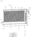
図4に示すように、蒸発器50及び凝縮器60は、いずれも並行流方式つまりパラレルフロー方式の熱交換器である。本実施形態の場合、蒸発器50及び凝縮器60は、例えばコルゲートフィンタイプの熱交換器である。本実施形態において、パラレルフロー方式とは、熱交換器の内部に、並行に設けられた複数の冷媒の通路を有するものをいう。この場合、熱交換器に流入した冷媒は、熱交換器内で複数の経路に分岐して並行に流れる。また、本実施形態において、コルゲートフィンタイプとは、波板状に形成された熱交換用のフィンを有する熱交換器を意味する。   As shown in FIG. 4, the evaporator 50 and the condenser 60 are both heat exchangers of a parallel flow type, that is, a parallel flow type. In the case of the present embodiment, the evaporator 50 and the condenser 60 are, for example, corrugated fin type heat exchangers. In the present embodiment, the parallel flow system refers to a system having a plurality of refrigerant passages provided in parallel inside a heat exchanger. In this case, the refrigerant flowing into the heat exchanger branches into a plurality of paths in the heat exchanger and flows in parallel. In the present embodiment, the corrugated fin type means a heat exchanger having heat exchange fins formed in a corrugated shape.

まず、蒸発器50について説明する。蒸発器50は、図4及び図5に示すように、流入側ヘッダ部51、流出側ヘッダ部52、複数のチューブプレート53、及び複数のコルゲートフィン54を有している。流入側ヘッダ部51及び流出側ヘッダ部52は、それぞれ断面が円形の管状に形成されて、内部に冷媒が通る流入側冷媒流路511及び流出側冷媒流路521を有している。流入側ヘッダ部51及び流出側ヘッダ部52は、一方側が開口し、他方側が閉塞している。   First, the evaporator 50 will be described. As shown in FIGS. 4 and 5, the evaporator 50 includes an inflow header 51, an outflow header 52, a plurality of tube plates 53, and a plurality of corrugated fins 54. Each of the inflow-side header portion 51 and the outflow-side header portion 52 is formed in a tubular shape having a circular cross section, and has an inflow-side refrigerant flow channel 511 and an outflow-side refrigerant flow channel 521 through which the refrigerant passes. The inflow-side header portion 51 and the outflow-side header portion 52 are open on one side and closed on the other side.

流入側ヘッダ部51の開口は、蒸発器50内に冷媒を流入させるための蒸発器用流入口512として機能する。流出側ヘッダ部52の開口は、蒸発器50から冷媒を流出させるための蒸発器用流出口522として機能する。ヒートポンプユニット40を循環する冷媒は、蒸発器用流入口512から蒸発器50内に流入し、蒸発器用流出口522から蒸発器50外に流出する。図3に示すように、蒸発器用流入口512は、減圧装置42の出力側に接続されている。また、蒸発器用流出口522は、圧縮機41の吸い込み側に接続されている。   The opening of the inflow-side header portion 51 functions as an evaporator inlet 512 for allowing the refrigerant to flow into the evaporator 50. The opening of the outflow side header portion 52 functions as an evaporator outlet 522 for allowing the refrigerant to flow out of the evaporator 50. The refrigerant circulating through the heat pump unit 40 flows into the evaporator 50 from the evaporator inlet 512 and flows out of the evaporator 50 from the evaporator outlet 522. As shown in FIG. 3, the evaporator inlet 512 is connected to the output side of the pressure reducing device 42. The evaporator outlet 522 is connected to the suction side of the compressor 41.

図4及び図5に示すように、流入側ヘッダ部51と流出側ヘッダ部52とは、所定距離離間した状態で、水平方向へ向かって相互に平行となるように配置されている。蒸発器50の流入側ヘッダ部51は、蒸発器50の流出側ヘッダ部52に対して下方に設けられている。したがって、蒸発器用流入口512は、蒸発器用流出口522に対して下方に設けられている。また、流入側ヘッダ部51と流出側ヘッダ部52とは、それぞれ内部を流れる冷媒の流れ方向が同一方向を向くように配置されている。したがって、循環風路30内における空気が流れる方向つまり図4の矢印A方向へ向かって蒸発器50を見た場合に、蒸発器用流入口512と蒸発器用流出口522とは、蒸発器50に対して対角の位置に設けられている。すなわち、図4の紙面左下部から蒸発器50内に流入した冷媒は、紙面右上部から蒸発器50外に流出する。   As shown in FIGS. 4 and 5, the inflow-side header portion 51 and the outflow-side header portion 52 are arranged so as to be parallel to each other in the horizontal direction with a predetermined distance therebetween. The inflow side header portion 51 of the evaporator 50 is provided below the outflow side header portion 52 of the evaporator 50. Therefore, the evaporator inlet 512 is provided below the evaporator outlet 522. Further, the inflow side header portion 51 and the outflow side header portion 52 are arranged so that the flow directions of the refrigerant flowing therein are in the same direction. Therefore, when the evaporator 50 is viewed in the direction in which the air flows in the circulation air passage 30, that is, in the direction of arrow A in FIG. 4, the evaporator inlet 512 and the evaporator outlet 522 are And are provided at diagonal positions. That is, the refrigerant that has flowed into the evaporator 50 from the lower left portion of FIG. 4 flows out of the evaporator 50 from the upper right portion of the paper.

複数のチューブプレート53は、上下に配置された流入側ヘッダ部51と流出側ヘッダ部52とを接続している。各チューブプレート53は、上下方向に長い長方形の板状に構成されている。そして、各チューブプレート53は、流入側ヘッダ部51及び流出側ヘッダ部52の長手方向に沿って一定間隔で配置されている。各チューブプレート53の面は、流入側ヘッダ部51及び流出側ヘッダ部52の長手方向に対して直交している。すなわち、各チューブプレート53の面は、循環風路30内における空気の流れ方向に対して直交している。   The plurality of tube plates 53 connect the inflow side header section 51 and the outflow side header section 52 arranged vertically. Each tube plate 53 is formed in a rectangular plate shape that is long in the vertical direction. The tube plates 53 are arranged at regular intervals along the longitudinal direction of the inflow header portion 51 and the outflow header portion 52. The surface of each tube plate 53 is orthogonal to the longitudinal direction of the inflow side header portion 51 and the outflow side header portion 52. That is, the surface of each tube plate 53 is orthogonal to the direction of air flow in the circulation air passage 30.

図5に示すように、チューブプレート53は、チューブプレート53の内部に冷媒を通すための通路531を複数本有している。チューブプレート53の下端部は、流入側ヘッダ部51を貫いて流入側冷媒流路511内に突出している。チューブプレート53の上端部は、流出側ヘッダ部52を貫いて流出側冷媒流路521内に突出している。そして、流入側冷媒流路511の下端部は、流入側ヘッダ部51の流入側冷媒流路511内に連通し、流入側冷媒流路511の上端部は、流出側ヘッダ部52の流出側冷媒流路521内に連通している。これにより、流入側ヘッダ部51の流入側冷媒流路511と、流出側ヘッダ部52の流出側冷媒流路521とは、通路531を介して連通している。   As shown in FIG. 5, the tube plate 53 has a plurality of passages 531 through which the refrigerant passes inside the tube plate 53. The lower end of the tube plate 53 protrudes into the inflow-side refrigerant flow path 511 through the inflow-side header 51. The upper end of the tube plate 53 protrudes into the outflow-side refrigerant passage 521 through the outflow-side header 52. The lower end of the inflow-side refrigerant flow path 511 communicates with the inflow-side refrigerant flow path 511 of the inflow-side header section 51, and the upper end of the inflow-side refrigerant flow path 511 communicates with the outflow-side refrigerant of the outflow-side header section 52. It communicates with the inside of the flow path 521. Thus, the inflow-side refrigerant flow path 511 of the inflow-side header section 51 and the outflow-side refrigerant flow path 521 of the outflow-side header section 52 communicate with each other via the passage 531.

コルゲートフィン54は、例えば薄いアルミ板を波状に折り曲げることで、全体として波板状に形成されている。コルゲートフィン54は、隣接するチューブプレート53の間に設けられている。コルゲートフィン54の波板状の両側において、波状の頂辺部は、チューブプレート53に接触して例えばろう接等によって固定されている。コルゲートフィン54は、熱交換用のフィンこの場合吸熱フィンとして機能する。つまり、チューブプレート53の流出側冷媒流路521を流れる冷媒と、コルゲートフィン54の波状の間を通る空気との間で、熱交換が行われる。   The corrugated fins 54 are formed in a corrugated shape as a whole, for example, by bending a thin aluminum plate into a corrugated shape. Corrugated fins 54 are provided between adjacent tube plates 53. On both sides of the corrugated fin 54 in the corrugated shape, the corrugated top sides are in contact with the tube plate 53 and fixed by, for example, brazing. The corrugated fin 54 functions as a fin for heat exchange, in this case, a heat absorbing fin. That is, heat exchange is performed between the refrigerant flowing through the outlet-side refrigerant flow path 521 of the tube plate 53 and the air passing between the corrugated fins 54.

凝縮器60は、図4及び図6に示すように、流入側ヘッダ部61、流出側ヘッダ部62、複数のチューブプレート63、及び複数のコルゲートフィン64を有している。凝縮器60は、基本的構成は蒸発器50と同様であるが、流入側ヘッダ部61及び流出側ヘッダ部62の配置が、蒸発器50と異なる。   As shown in FIGS. 4 and 6, the condenser 60 includes an inflow header portion 61, an outflow header portion 62, a plurality of tube plates 63, and a plurality of corrugated fins 64. The condenser 60 has the same basic configuration as the evaporator 50, but is different from the evaporator 50 in the arrangement of the inflow header 61 and the outflow header 62.

すなわち、流入側ヘッダ部61及び流出側ヘッダ部62は、蒸発器50の流入側ヘッダ部51及び流出側ヘッダ部52と同様に、それぞれ断面が円形の管状に形成されて、内部に冷媒が通る流入側冷媒流路611及び流出側冷媒流路621を有している。流入側ヘッダ部61及び流出側ヘッダ部62は、一方側が開口し、他方側が閉塞している。   That is, the inflow-side header section 61 and the outflow-side header section 62 are each formed in a tubular shape with a circular cross section, similarly to the inflow-side header section 51 and the outflow-side header section 52 of the evaporator 50, and the refrigerant passes through the inside. It has an inflow-side refrigerant channel 611 and an outflow-side refrigerant channel 621. The inflow side header part 61 and the outflow side header part 62 are open on one side and closed on the other side.

流入側ヘッダ部61の開口は、凝縮器60内に冷媒を流入させるための凝縮器用流入口612として機能する。流出側ヘッダ部62の開口は、凝縮器60から冷媒を流出させるための凝縮器用流出口622として機能する。ヒートポンプユニット40を循環する冷媒は、凝縮器用流入口612から凝縮器60内に流入し、凝縮器用流出口622から凝縮器60外に流出する。図3に示すように、凝縮器用流入口612は、圧縮機41の吐出側に接続されている。凝縮器用流出口622は、減圧装置42の入力側に接続されている。   The opening of the inflow-side header portion 61 functions as a condenser inlet 612 for allowing the refrigerant to flow into the condenser 60. The opening of the outflow side header portion 62 functions as a condenser outlet 622 for allowing the refrigerant to flow out of the condenser 60. The refrigerant circulating in the heat pump unit 40 flows into the condenser 60 from the condenser inlet 612, and flows out of the condenser 60 from the condenser outlet 622. As shown in FIG. 3, the condenser inlet 612 is connected to the discharge side of the compressor 41. The outlet 622 for the condenser is connected to the input side of the pressure reducing device 42.

図4及び図6に示すように、流入側ヘッダ部61と流出側ヘッダ部62とは、蒸発器50の流入側ヘッダ部51と流出側ヘッダ部52と同様に、所定距離離間した状態で、水平方向へ向かって相互に平行となるように配置されている。凝縮器60の流入側ヘッダ部61は、凝縮器60の流出側ヘッダ部62に対して上方に設けられている。したがって、凝縮器用流入口612は、凝縮器用流出口622に対して上方に設けられている。また、流入側ヘッダ部61と流出側ヘッダ部62とは、それぞれ内部を流れる冷媒の流れ方向が同一方向を向くように配置されている。したがって、循環風路30内における空気が流れる方向つまり図4の矢印A方向へ向かって凝縮器60を見た場合に、凝縮器用流入口612と凝縮器用流出口622とは、凝縮器60に対して対角の位置に設けられている。すなわち、図6の紙面右上側から凝縮器60内に流入した冷媒は、紙面左下側から凝縮器60外に流出する   As shown in FIGS. 4 and 6, the inflow side header portion 61 and the outflow side header portion 62 are separated from each other by a predetermined distance, like the inflow side header portion 51 and the outflow side header portion 52 of the evaporator 50. They are arranged so as to be parallel to each other in the horizontal direction. The inflow header portion 61 of the condenser 60 is provided above the outflow header portion 62 of the condenser 60. Therefore, the condenser inlet 612 is provided above the condenser outlet 622. Further, the inflow-side header portion 61 and the outflow-side header portion 62 are arranged such that the flow directions of the refrigerant flowing therein are in the same direction. Accordingly, when the condenser 60 is viewed in the direction in which the air flows in the circulation air passage 30, that is, in the direction of arrow A in FIG. 4, the condenser inlet 612 and the condenser outlet 622 are And are provided at diagonal positions. That is, the refrigerant flowing into the condenser 60 from the upper right side of the paper of FIG. 6 flows out of the condenser 60 from the lower left side of the paper.

複数のチューブプレート63は、蒸発器50のチューブプレート53と同様に、上下に配置された流入側ヘッダ部61と流出側ヘッダ部62とを接続している。各チューブプレート63は、上下方向に長い長方形の板状に構成されている。そして、各チューブプレート63は、流入側ヘッダ部61及び流出側ヘッダ部62の長手方向に沿って一定間隔で配置されている。各チューブプレート63の面は、流入側ヘッダ部61及び流出側ヘッダ部62の長手方向に対して直交している。すなわち、各チューブプレート63の面は、循環風路30内における空気の流れ方向に対して直交している。   Similarly to the tube plate 53 of the evaporator 50, the plurality of tube plates 63 connect the inflow side header portion 61 and the outflow side header portion 62 arranged vertically. Each tube plate 63 is formed in a rectangular plate shape that is long in the vertical direction. The tube plates 63 are arranged at regular intervals along the longitudinal direction of the inflow side header portion 61 and the outflow side header portion 62. The surface of each tube plate 63 is orthogonal to the longitudinal direction of the inflow side header portion 61 and the outflow side header portion 62. That is, the surface of each tube plate 63 is orthogonal to the direction of air flow in the circulation air passage 30.

図6に示すように、チューブプレート63は、チューブプレート63の内部に冷媒を通すための通路631を複数本有している。チューブプレート63の上端部は、流入側ヘッダ部61を貫いて流入側冷媒流路611内に突出している。チューブプレート63の下端部は、流出側ヘッダ部62を貫いて流出側冷媒流路621内に突出している。そして、流入側冷媒流路611の上端部は、流入側ヘッダ部61の流入側冷媒流路611内に連通し、流入側冷媒流路611の下端部は、流出側ヘッダ部62の流出側冷媒流路621内に連通している。これにより、流入側ヘッダ部61の流入側冷媒流路611と、流出側ヘッダ部62の流出側冷媒流路621とは、通路631を介して連通している。なお、コルゲートフィン64は、蒸発器50のコルゲートフィン54と同様の構成であるため、説明を省略する。   As shown in FIG. 6, the tube plate 63 has a plurality of passages 631 for passing the refrigerant inside the tube plate 63. The upper end of the tube plate 63 protrudes into the inflow-side refrigerant flow path 611 through the inflow-side header 61. The lower end of the tube plate 63 protrudes into the outflow-side refrigerant passage 621 through the outflow-side header 62. The upper end of the inflow-side refrigerant flow path 611 communicates with the inflow-side refrigerant flow path 611 of the inflow-side header section 61, and the lower end of the inflow-side refrigerant flow path 611 communicates with the outflow-side refrigerant of the outflow-side header section 62. It communicates with the inside of the flow path 621. Thus, the inflow-side refrigerant flow channel 611 of the inflow-side header portion 61 and the outflow-side refrigerant flow channel 621 of the outflow-side header portion 62 communicate with each other via the passage 631. Note that the corrugated fin 64 has the same configuration as the corrugated fin 54 of the evaporator 50, and thus the description is omitted.

本実施形態において、蒸発器50及び凝縮器60の外形は、同一形状であって、図5における蒸発器50の中心及び図6における凝縮器60の中心を基準とした点対称形に構成されている。また、詳細は図示しないが、減圧装置42は、蒸発器用流入口512及び凝縮器用流出口622の上方に設けられている。
上記した実施形態によれば、次のような作用効果を得ることができる。
In the present embodiment, the outer shapes of the evaporator 50 and the condenser 60 have the same shape, and are configured to be point-symmetric with respect to the center of the evaporator 50 in FIG. 5 and the center of the condenser 60 in FIG. I have. Although not shown in detail, the pressure reducing device 42 is provided above the evaporator inlet 512 and the condenser outlet 622.
According to the above-described embodiment, the following operational effects can be obtained.

ヒートポンプユニット40の熱交換器である蒸発器50及び凝縮器60は、パラレルフロー方式でコルゲートフィンタイプの熱交換器である。コルゲートフィンタイプの熱交換器50、60は、コルゲートフィン54、64が波板状に形成されているため、従来用いられているフィンチューブタイプの熱交換器に比べて、熱交換に寄与する面積(以下、熱交換面積と称する)を大きくすることができる。このため、コルゲートフィンタイプの熱交換器50、60は、フィンチューブタイプの熱交換器に比べて、冷媒と空気との熱交換効率を高くすることができる。したがって、熱交換器50、60を大型化することなく、熱交換器50、60の熱交換効率を向上させることができる。   The evaporator 50 and the condenser 60 which are the heat exchangers of the heat pump unit 40 are corrugated fin type heat exchangers in a parallel flow system. Corrugated fin type heat exchangers 50 and 60 have corrugated fins 54 and 64 formed in a corrugated plate shape, and therefore have an area that contributes to heat exchange as compared with conventionally used fin tube type heat exchangers. (Hereinafter, referred to as a heat exchange area) can be increased. Therefore, the heat exchangers 50 and 60 of the corrugated fin type can increase the heat exchange efficiency between the refrigerant and the air as compared with the heat exchanger of the fin tube type. Therefore, the heat exchange efficiency of the heat exchangers 50 and 60 can be improved without increasing the size of the heat exchangers 50 and 60.

ここで、蒸発器50及び凝縮器60は、パラレルフロー方式であるため、図5及び図6に示すように、冷媒を並列に流すために複数の通路531、631を有している。なお、以下の説明では、蒸発器50と凝縮器60とを総称する場合には単に熱交換器50、60とする。熱交換器50、60内に、複数の通路531、631が並列で設けられていると、熱交換器50、60内に流入した冷媒は、複数の通路531、631において抵抗がより小さい経路を通ろうとする。   Here, since the evaporator 50 and the condenser 60 are of a parallel flow type, they have a plurality of passages 531 and 631 for flowing the refrigerant in parallel as shown in FIGS. In the following description, the evaporator 50 and the condenser 60 are simply referred to as the heat exchangers 50 and 60. When the plurality of passages 531 and 631 are provided in parallel in the heat exchangers 50 and 60, the refrigerant flowing into the heat exchangers 50 and 60 passes through the paths having smaller resistance in the plurality of passages 531 and 631. Try to pass.

この場合、例えば蒸発器50において、蒸発器用流入口512が蒸発器用流出口522よりも上方に設けられていると、次のような問題が生じる。すなわち、蒸発器50には、減圧装置42から流出した低圧で液状の冷媒R1が流入する。その際、蒸発器用流入口512が蒸発器用流出口522よりも上方に設けられていると、蒸発器用流入口512から蒸発器50内に流入した低圧液状の冷媒R1は、重力の作用により、蒸発器用流入口512に近い通路531を通って落下しようとする。これにより、蒸発器50内を通る冷媒の流れは、蒸発器用流入口512に近い通路531に偏り易くなる。このように蒸発器50内を通る冷媒の流れに偏りが生じると、蒸発器50全体で均一に熱交換することができなくなる。したがって、蒸発器用流入口512が蒸発器用流出口522よりも上方に設けられているものでは、蒸発器50の全体を十分に活用することができない。   In this case, for example, if the evaporator inlet 512 is provided above the evaporator outlet 522 in the evaporator 50, the following problem occurs. That is, the low-pressure liquid refrigerant R1 flowing out of the pressure reducing device 42 flows into the evaporator 50. At this time, if the evaporator inlet 512 is provided above the evaporator outlet 522, the low-pressure liquid refrigerant R1 flowing into the evaporator 50 from the evaporator inlet 512 is evaporated by the action of gravity. An attempt is made to fall through a passage 531 near the dexterous inlet 512. Thereby, the flow of the refrigerant passing through the inside of the evaporator 50 tends to be biased toward the passage 531 near the evaporator inlet 512. When the flow of the refrigerant passing through the inside of the evaporator 50 is biased in this way, it is impossible to uniformly exchange heat with the entire evaporator 50. Therefore, if the evaporator inlet 512 is provided above the evaporator outlet 522, the entire evaporator 50 cannot be fully utilized.

これに対し、本実施形態の蒸発器50において蒸発器用流入口512は、図5に示すように、蒸発器用流出口522よりも下方に設けられている。これによれば、蒸発器50内に流入した低圧液状の冷媒R1は、まず、流入側ヘッダ部51の流入側冷媒流路511内に貯留される。そして、流入側冷媒流路511内が液状の冷媒で充満されると、蒸発器用流入口512から更に流入しようとする冷媒によって、流入側冷媒流路511内が加圧される。これにより、流入側冷媒流路511内の冷媒R1が押し出されるようにして、各通路531を通って上昇する。そして、低圧液状の冷媒R1は、通路531を通過する際に循環風路30を通る空気と熱交換されて、徐々に低圧ガス状の冷媒R2になる。   On the other hand, in the evaporator 50 of the present embodiment, the evaporator inlet 512 is provided below the evaporator outlet 522 as shown in FIG. According to this, the low-pressure liquid refrigerant R <b> 1 flowing into the evaporator 50 is first stored in the inflow-side refrigerant flow path 511 of the inflow-side header 51. When the inside of the inflow-side refrigerant flow path 511 is filled with the liquid refrigerant, the inside of the inflow-side refrigerant flow path 511 is pressurized by the refrigerant that is going to flow further from the evaporator inlet 512. Thereby, the refrigerant R1 in the inflow-side refrigerant flow path 511 is pushed out and rises through each passage 531. The low-pressure liquid refrigerant R1 exchanges heat with the air passing through the circulation air passage 30 when passing through the passage 531 to gradually become the low-pressure gaseous refrigerant R2.

このように、本実施形態によれば、流入側冷媒流路511内を、蒸発器用流入口512から流入する低圧液状の冷媒R2で満たすことで、流入側冷媒流路511内に充満する低圧液状の冷媒R2は、各通路531を均一に通って流出側冷媒流路521側へ流れる。これにより、蒸発器50内を通る冷媒の流れが、蒸発器用流入口512に近い通路531に偏ることを抑制することができる。したがって、蒸発器50全体で均一に熱交換することができるようになり、その結果、蒸発器50全体を十分に活用して熱交換効率を向上させることができる。   As described above, according to the present embodiment, by filling the inside of the inflow-side refrigerant flow path 511 with the low-pressure liquid refrigerant R2 flowing from the evaporator inflow port 512, the low-pressure liquid filled in the inflow-side refrigerant flow path 511 is filled. Refrigerant R2 flows through each passage 531 uniformly to the outflow-side refrigerant flow path 521 side. Thereby, it is possible to suppress the flow of the refrigerant passing through the inside of the evaporator 50 from being biased toward the passage 531 near the evaporator inlet 512. Therefore, the heat can be uniformly exchanged in the entire evaporator 50, and as a result, the heat exchange efficiency can be improved by making full use of the entire evaporator 50.

また、例えば凝縮器60において、凝縮器用流入口612が凝縮器用流出口622よりも下方に設けられていると、次のような問題が生じる。すなわち、凝縮器60には、圧縮機41から流出した高温高圧のガス状の冷媒R3が流入する。その際、凝縮器用流入口612が凝縮器用流出口622よりも下方に設けられていると、凝縮器用流入口612から凝縮器60内に流入した高圧ガス状の冷媒R3は、凝縮器用流入口612に近い通路631を通って上昇しようとする。これにより、凝縮器60内を通る冷媒の流れは、凝縮器用流入口612に近い通路631に偏り易くなる。このように凝縮器60内を通る冷媒の流れに偏りが生じると、凝縮器60全体で均一に熱交換することができなくなる。したがって、凝縮器用流入口612が凝縮器用流出口622よりも下方に設けられているものでは、凝縮器60の全体を十分に活用することができない。   Further, for example, in the condenser 60, if the condenser inlet 612 is provided below the condenser outlet 622, the following problem occurs. That is, the high-temperature and high-pressure gaseous refrigerant R3 flowing out of the compressor 41 flows into the condenser 60. At this time, if the condenser inlet 612 is provided below the condenser outlet 622, the high-pressure gaseous refrigerant R3 flowing into the condenser 60 from the condenser inlet 612 is discharged from the condenser inlet 612. Trying to ascend through a passage 631 close to. Accordingly, the flow of the refrigerant passing through the inside of the condenser 60 tends to be biased toward the passage 631 near the inlet 612 for the condenser. When the flow of the refrigerant passing through the inside of the condenser 60 is biased in this way, it is impossible to uniformly exchange heat in the entire condenser 60. Therefore, if the condenser inlet 612 is provided below the condenser outlet 622, the entire condenser 60 cannot be fully utilized.

これに対し、本実施形態の凝縮器60において凝縮器用流入口612は、図6に示すように、凝縮器用流出口622よりも上方に設けられている。これによれば、凝縮器60内に流入した高圧ガス状の冷媒R3は、まず、流入側ヘッダ部61の流入側冷媒流路611内に貯留される。そして、流入側冷媒流路611内がガス状の冷媒R3で充満されると、凝縮器用流入口612から更に流入しようとする冷媒によって、流入側冷媒流路611内が加圧される。これにより、流入側冷媒流路611内の冷媒R3が押し出されるようにして、通路631を通って下降する。そして、高圧ガス状の冷媒R3は、通路631を通過する際に循環風路30を通る空気と熱交換されて、高圧液状の冷媒R4になる。   On the other hand, in the condenser 60 of the present embodiment, the condenser inlet 612 is provided above the condenser outlet 622 as shown in FIG. According to this, the high-pressure gaseous refrigerant R3 flowing into the condenser 60 is first stored in the inflow-side refrigerant flow path 611 of the inflow-side header portion 61. Then, when the inside of the inflow-side refrigerant flow path 611 is filled with the gaseous refrigerant R3, the inside of the inflow-side refrigerant flow path 611 is pressurized by the refrigerant that is about to flow in from the condenser inlet 612. Thereby, the refrigerant R3 in the inflow-side refrigerant flow path 611 is pushed out and descends through the passage 631. Then, when passing through the passage 631, the high-pressure gaseous refrigerant R3 undergoes heat exchange with the air passing through the circulation air passage 30 to become a high-pressure liquid refrigerant R4.

このように、本実施形態によれば、流入側冷媒流路611内を、凝縮器用流入口612から流入する高圧ガス状の冷媒R3で満たすことで、流入側冷媒流路611内に充満する高圧ガス状の冷媒R3は、各通路613を均一に通って流出側冷媒流路621側へ流れる。これにより、凝縮器60内を通る冷媒の流れが、凝縮器用流入口612に近い通路631に偏ることを抑制することができる。したがって、凝縮器60全体で均一に熱交換することができるようになり、その結果、凝縮器60全体を十分に活用して熱交換効率を向上させることができる。   As described above, according to the present embodiment, by filling the inside of the inflow-side refrigerant flow path 611 with the high-pressure gaseous refrigerant R3 flowing from the condenser inlet 612, the high-pressure gas filling the inflow-side refrigerant flow path 611 is filled. The gaseous refrigerant R3 uniformly flows through each passage 613 and flows to the outflow-side refrigerant flow path 621 side. Thereby, it is possible to suppress the flow of the refrigerant passing through the inside of the condenser 60 from being biased toward the passage 631 close to the inlet 612 for the condenser. Therefore, the heat can be uniformly exchanged in the entire condenser 60, and as a result, the heat exchange efficiency can be improved by fully utilizing the entire condenser 60.

更に、図4及び図5に示すように、蒸発器用流入口512と蒸発器用流出口522とは、蒸発器50に対して対角の位置に設けられている。これによれば、図5に示すように、蒸発器用流入口512から蒸発器用流出口522に至る経路について、いずれの通路531を通ったとしても、各経路の距離を均等にすることができる。同様に、図4及び図6に示すように、凝縮器用流入口612と凝縮器用流出口622とは、凝縮器60に対して対角の位置に設けられている。これによれば、凝縮器用流入口612から凝縮器用流出口622に至る経路について、いずれの通路631を通ったとしても、各経路の距離を均等にすることができる。   4 and 5, the evaporator inlet 512 and the evaporator outlet 522 are provided at diagonal positions with respect to the evaporator 50. According to this, as shown in FIG. 5, the distance from the evaporator inlet 512 to the evaporator outlet 522 can be equalized even if any of the paths 531 pass. Similarly, as shown in FIGS. 4 and 6, the condenser inlet 612 and the condenser outlet 622 are provided at diagonal positions with respect to the condenser 60. According to this, with respect to the path from the condenser inlet 612 to the condenser outlet 622, the distance of each path can be equalized irrespective of the path 631.

このように、蒸発器50及び凝縮器60内を並列に流れる冷媒の経路について、各経路の距離を均等にすることで、各経路の流路抵抗を均等にすることができる。したがって、蒸発器50及び凝縮器60内を流れる冷媒に偏りが生じることを抑制することができ、その結果、蒸発器50及び凝縮器60全体を十分に活用して熱交換効率を更に向上させることができる。   In this way, by equalizing the distance between the respective paths of the refrigerant flowing in parallel in the evaporator 50 and the condenser 60, the flow path resistance of each path can be equalized. Therefore, it is possible to prevent the refrigerant flowing in the evaporator 50 and the condenser 60 from being biased. As a result, the heat exchange efficiency is further improved by fully utilizing the entire evaporator 50 and the condenser 60. Can be.

(第2実施形態)
次に、第2実施形態について、図7及び図8を参照して説明する。
本実施形態の洗濯乾燥機10は、2つ以上の蒸発器及び2つ以上の凝縮器が空気の流れ方向に向かって重ねて配置されている点で、上記第1実施形態とは異なる。
(2nd Embodiment)
Next, a second embodiment will be described with reference to FIGS.
The washer-dryer 10 of the present embodiment is different from the first embodiment in that two or more evaporators and two or more condensers are arranged in an overlapping manner in the direction of air flow.

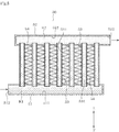
すなわち、第2実施形態の洗濯乾燥機10は、熱交換部71と、第1蒸発器501及び第2蒸発器502と、第1凝縮器601及び第2凝縮器602と、を備えている。熱交換部71は、基本的な構成は上記第1実施形態の熱交換部34と同様であるが、内部の容積つまり断面積が、上記第1実施形態の熱交換部34の内部容積に比べて小さく設定されている。この場合、本実施形態の熱交換部71の断面積は、第1実施形態の熱交換部34の断面積に対して約半分に設定されている。   That is, the washer-dryer 10 of the second embodiment includes the heat exchange unit 71, the first evaporator 501 and the second evaporator 502, and the first condenser 601 and the second condenser 602. The heat exchange unit 71 has the same basic configuration as the heat exchange unit 34 of the first embodiment, but has an internal volume, that is, a cross-sectional area that is smaller than that of the heat exchange unit 34 of the first embodiment. It is set small. In this case, the cross-sectional area of the heat exchange unit 71 of the present embodiment is set to be approximately half the cross-sectional area of the heat exchange unit 34 of the first embodiment.

第1蒸発器501及び第2蒸発器502は、基本的な構成は上記第1実施形態の蒸発器50と同様であるが、熱交換面積が、第1実施形態の蒸発器50の熱交換面積に比べて小さく設定されている。そして、第1蒸発器501及び第2蒸発器502は、各蒸発器501、502の熱交換面積を合算した値が、第1実施形態の蒸発器50の熱交換面積と同等以上になるように設定されている。本実施形態の場合、第1蒸発器501及び第2蒸発器502の熱交換面積は、第1実施形態の蒸発器50の熱交換面積の約半分に設定されている。この場合、第1蒸発器501及び第2蒸発器502は、主にヘッダ部51、61の延伸方向(図8では左右方向)を短くすることで、熱交換面積を減らしている。   The first evaporator 501 and the second evaporator 502 have the same basic configuration as the evaporator 50 of the first embodiment, but have a heat exchange area of the evaporator 50 of the first embodiment. It is set smaller than. The first evaporator 501 and the second evaporator 502 are configured such that the sum of the heat exchange areas of the evaporators 501 and 502 is equal to or greater than the heat exchange area of the evaporator 50 of the first embodiment. Is set. In the case of the present embodiment, the heat exchange area of the first evaporator 501 and the second evaporator 502 is set to about half of the heat exchange area of the evaporator 50 of the first embodiment. In this case, the first evaporator 501 and the second evaporator 502 reduce the heat exchange area mainly by shortening the extending direction (the left-right direction in FIG. 8) of the header portions 51, 61.

第1蒸発器501及び第2蒸発器502は、熱交換部71内において、熱交換部71内を流れる空気の流れ方向へ向かって重ねて配置されている。例えば第1蒸発器501は、第2蒸発器502に対して、空気の流れ方向における上流側に配置されている。第1蒸発器501を通過して除湿及び冷却された空気は、その後、第2蒸発器502を通過することで更に除湿及び冷却される。   The first evaporator 501 and the second evaporator 502 are arranged inside the heat exchange unit 71 so as to overlap in the flow direction of the air flowing through the heat exchange unit 71. For example, the first evaporator 501 is disposed upstream of the second evaporator 502 in the air flow direction. The air dehumidified and cooled after passing through the first evaporator 501 is further dehumidified and cooled by passing through the second evaporator 502.

第1蒸発器501と第2蒸発器502とは、並列に接続されている。すなわち、減圧装置42から流出した冷媒は、第1蒸発器501及び第2蒸発器502の手前で二手に分岐して、各蒸発器501、502の蒸発器用流入口512から各蒸発器501、502内に流入する。そして、各蒸発器501、502内を流れた冷媒は、各蒸発器501、502の蒸発器用流出口522から流出した後、合流して圧縮機41に吸い込まれる。   The first evaporator 501 and the second evaporator 502 are connected in parallel. That is, the refrigerant flowing out of the decompression device 42 is branched into two parts before the first evaporator 501 and the second evaporator 502, and the respective evaporators 501, 502 are provided through the evaporator inlets 512 of the evaporators 501, 502. Flows into. Then, the refrigerant flowing in each of the evaporators 501 and 502 flows out from the evaporator outlet 522 of each of the evaporators 501 and 502, and then merges and is sucked into the compressor 41.

また、第1凝縮器601及び第2凝縮器602は、基本的な構成は上記第1実施形態の凝縮器60と同様であるが、熱交換面積が、第1実施形態の凝縮器60の熱交換面積に比べて小さく設定されている。そして、第1凝縮器601及び第2凝縮器602は、各凝縮器601、602の熱交換面積を合算した値が、第1実施形態の凝縮器60の熱交換面積と同等以上になるように設定されている。本実施形態の場合、第1凝縮器601及び第2凝縮器602の熱交換面積は、第1実施形態の凝縮器60の熱交換面積の約半分に設定されている。   The first condenser 601 and the second condenser 602 have the same basic configuration as the condenser 60 of the first embodiment, but have a heat exchange area of the heat of the condenser 60 of the first embodiment. It is set smaller than the exchange area. The first condenser 601 and the second condenser 602 are configured such that the sum of the heat exchange areas of the condensers 601 and 602 is equal to or greater than the heat exchange area of the condenser 60 of the first embodiment. Is set. In the case of the present embodiment, the heat exchange area of the first condenser 601 and the second condenser 602 is set to about half of the heat exchange area of the condenser 60 of the first embodiment.

第1凝縮器601及び第2凝縮器602は、熱交換部71内において、熱交換部71内を流れる空気の流れ方向へ向かって重ねて配置されている。例えば第1凝縮器601は、第2凝縮器602に対して、空気の流れ方向における上流側に配置されている。第1凝縮器601を通過して加熱された空気は、その後、第2凝縮器602を通過することで更に加熱される。   The first condenser 601 and the second condenser 602 are arranged in the heat exchange unit 71 so as to overlap with each other in the flow direction of the air flowing through the heat exchange unit 71. For example, the first condenser 601 is disposed upstream of the second condenser 602 in the air flow direction. The air heated by passing through the first condenser 601 is then further heated by passing through the second condenser 602.

第1凝縮器601と第2凝縮器602とは、並列に接続されている。すなわち、圧縮機41から吐出された冷媒は、第1凝縮器601及び第2凝縮器602の手前で二手に分岐して、各凝縮器601、602の凝縮器用流入口612から各凝縮器601、602内に流入する。そして、各凝縮器601、602内を流れた冷媒は、各凝縮器601、602の凝縮器用流出口622から流出した後、合流して減圧装置42内に流入する。   The first condenser 601 and the second condenser 602 are connected in parallel. That is, the refrigerant discharged from the compressor 41 is branched into two parts before the first condenser 601 and the second condenser 602, and the respective condensers 601, 601,. It flows into 602. Then, the refrigerant flowing in each of the condensers 601 and 602 flows out from the condenser outlet 622 of each of the condensers 601 and 602, and then joins and flows into the decompression device 42.

このような第2実施形態によれば、上記第1実施形態と同様の作用効果が得られる。更に、第2実施形態によれば、蒸発器50に比べて小型化した複数の蒸発器501、502と、凝縮器60に比べて小型化した複数の凝縮器601、602とを、それぞれ重ねて配置している。したがって、各蒸発器501、502及び各凝縮器601、602を収容する熱交換部34の断面積を小さくすることができ、これにより、熱交換部71の小型化を行うことができる。その結果、洗濯乾燥機10全体の小型化や、水槽12の大型化つまり衣類の収容量の大容量化を図ることができる。   According to the second embodiment, the same operation and effect as those of the first embodiment can be obtained. Further, according to the second embodiment, the plurality of evaporators 501 and 502 that are smaller than the evaporator 50 and the plurality of condensers 601 and 602 that are smaller than the condenser 60 are respectively stacked. Have been placed. Therefore, it is possible to reduce the cross-sectional area of the heat exchange unit 34 that accommodates each of the evaporators 501 and 502 and each of the condensers 601 and 602, so that the heat exchange unit 71 can be downsized. As a result, it is possible to reduce the size of the entire washer / dryer 10 and increase the size of the water tub 12, that is, increase the capacity of storing clothes.

ちなみに、先に述べた特許文献1の図1に示される従来技術では、前ダクト(17)の通風面積に対して、前ダクト(17)の下流側に設けられた循環風路(19)の通風面積の方が大きくなっている。このような構成においては、前ダクト(17)から循環風路(19)に吹き込む風に乱れが生じ易く、特に循環風路(19)内の外周部付近において風が乱れ易い。このように、前ダクト(17)と循環風路(19)との通風面積に差があると、エバポレータ(23)を通過する風の風量は、エバポレータ(23)に対する位置によって差が生じ易くなる。例えば風の乱れが小さいエバポレータ(23)の中央部に比べて、風の乱れが大きいエバポレータ(23)の外周部付近は、熱交換効率が低下しがちである。一方、第2実施形態のように、熱交換部34の風路の断面積を小さくすることで、接続ダクト33との断面積の差を減らすことができる。その結果、熱交換部34内を通る風の乱れを低減し、蒸発器501、502、及び凝縮器601、602の外周部付近における熱交換効率を高めることができる。なお、上記の括弧内の数字は、特許文献1における符号を示している。   By the way, in the prior art shown in FIG. 1 of Patent Document 1 described above, the circulation air passage (19) provided on the downstream side of the front duct (17) with respect to the ventilation area of the front duct (17). The ventilation area is larger. In such a configuration, the wind blown from the front duct (17) into the circulation air passage (19) is likely to be disturbed, and particularly the wind is likely to be disturbed near the outer peripheral portion in the circulation air passage (19). As described above, when there is a difference in the ventilation area between the front duct (17) and the circulation air passage (19), the flow rate of the wind passing through the evaporator (23) tends to be different depending on the position with respect to the evaporator (23). . For example, the heat exchange efficiency tends to be lower near the outer periphery of the evaporator (23) where the wind turbulence is large compared to the center of the evaporator (23) where the wind turbulence is small. On the other hand, as in the second embodiment, by reducing the cross-sectional area of the air passage of the heat exchange section 34, the difference in the cross-sectional area with the connection duct 33 can be reduced. As a result, the turbulence of the wind passing through the heat exchange unit 34 can be reduced, and the heat exchange efficiency near the outer peripheral portions of the evaporators 501 and 502 and the condensers 601 and 602 can be increased. The numbers in parentheses above indicate the reference numbers in Patent Document 1.

第2実施形態は、蒸発器501、502と凝縮器601、602とを、第1実施形態の蒸発器50や凝縮器60に比べて、主にヘッダ部51、61の延伸方向(図8では左右方向)を短くすることで、その熱交換面積を減らす構成である。その理由は、先に述べたように、冷媒はヘッダ部51、61の入口に近い位置にある通路531、631から落下或いは上昇しようとする。即ち、この種の蒸発器や凝縮器において、ヘッダ部の入口から遠い位置にある通路は、ヘッダ部の入口から近い位置にある通路に比べて、熱交換効率が劣り易くなる性質がある。よってこの第2実施形態では、ヘッダ部51、61の入口512、612から遠い位置にある効率の悪い通路を削除し、ヘッダ部51、61の入口512、612に近い位置にある効率の良い通路のみを残している。そして、それによって減少した熱交換面積を、2つ以上の蒸発器、或いは2つ以上の凝縮器を、空気の流れ方向に向かって重ねて配置することにより補う構成としている。その結果、この第2実施形態によれば、蒸発器や凝縮器の効率の良い部分だけを利用して性能を一層向上させることができる。   In the second embodiment, the evaporators 501 and 502 and the condensers 601 and 602 are different from the evaporator 50 and the condenser 60 of the first embodiment mainly in the extending direction of the header portions 51 and 61 (in FIG. 8, This is a configuration in which the heat exchange area is reduced by shortening the horizontal direction. The reason is, as described above, the refrigerant tends to drop or ascend from the passages 531, 631 located near the entrances of the header portions 51, 61. That is, in this type of evaporator or condenser, the passage at a position far from the entrance of the header portion has a property that the heat exchange efficiency tends to be inferior to the passage at a position near the entrance of the header portion. Therefore, in the second embodiment, the inefficient passage located far from the entrances 512 and 612 of the header portions 51 and 61 is deleted, and the efficient passage located near the entrances 512 and 612 of the header portions 51 and 61 is deleted. Only leave. The heat exchange area reduced thereby is compensated for by arranging two or more evaporators or two or more condensers in an overlapping manner in the air flow direction. As a result, according to the second embodiment, the performance can be further improved by using only the efficient portions of the evaporator and the condenser.

(他の実施形態)
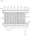
次に、他の実施形態について、図9及び図10を参照して説明する。なお、図9及び図10では、共通の図面を用いて蒸発器50及び凝縮器60を示している。
図9及び図10に示すように、他の実施形態において、蒸発器50の蒸発器用流入口512及び蒸発器用流出口522は、蒸発器50において同じ側面に設けられている。つまり、蒸発器50において、流入側冷媒流路511内を流れる冷媒の向きは、流出側冷媒流路521内を流れる冷媒の向きに対して逆向きとなる。また、凝縮器60の凝縮器用流入口612及び凝縮器用流出口622は、凝縮器60において同じ側面に設けられている。すなわち、凝縮器60において、流入側冷媒流路611内を流れる冷媒の向きは、流出側冷媒流路621内を流れる冷媒の向きに対して逆向きとなる。
(Other embodiments)
Next, another embodiment will be described with reference to FIGS. 9 and 10. 9 and 10 show the evaporator 50 and the condenser 60 using a common drawing.
As shown in FIGS. 9 and 10, in another embodiment, the evaporator inlet 512 and the evaporator outlet 522 of the evaporator 50 are provided on the same side surface of the evaporator 50. That is, in the evaporator 50, the direction of the refrigerant flowing in the inflow-side refrigerant flow path 511 is opposite to the direction of the refrigerant flowing in the outflow-side refrigerant flow path 521. The condenser inlet 612 and the condenser outlet 622 of the condenser 60 are provided on the same side surface of the condenser 60. That is, in the condenser 60, the direction of the refrigerant flowing in the inflow-side refrigerant flow path 611 is opposite to the direction of the refrigerant flowing in the outflow-side refrigerant flow path 621.

そして、図9に示す蒸発器50及び凝縮器60は、各流入口512、612及び各流出口522、622からの距離が遠くなるほど、隣接するチューブプレート53、63の間隔が狭くなるように設定されている。つまり、蒸発器50及び凝縮器60は、各流入口512、612及び各流出口522、622からの距離が遠くなるほど、チューブプレート53、63の密度が高くなるように設定されている。例えば、本実施形態では、隣接するチューブプレート53、63の間隔は、各流入口512、612及び各流出口522、622に近い方から順に、第1間隔L1、第2間隔L2、及び第3間隔L3となるように3段階に設定されている。この場合、第1間隔L1>第2間隔L2>第3間隔L3である。   The evaporator 50 and the condenser 60 shown in FIG. 9 are set such that the distance from the inlets 512 and 612 and the outlets 522 and 622 increases, and the distance between the adjacent tube plates 53 and 63 decreases. Have been. That is, the evaporator 50 and the condenser 60 are set such that the greater the distance from each of the inlets 512 and 612 and each of the outlets 522 and 622, the higher the density of the tube plates 53 and 63. For example, in the present embodiment, the intervals between the adjacent tube plates 53 and 63 are the first interval L1, the second interval L2, and the third interval in order from the one closer to the inlets 512 and 612 and the outlets 522 and 622. Three levels are set so as to be the interval L3. In this case, the first interval L1> the second interval L2> the third interval L3.

また、図10に示す蒸発器50及び凝縮器60は、各流入口512、612及び各流出口522、622からの距離が遠くなるほど、チューブプレート53、63内の通路531、631が太くなるように設定されている。つまり、蒸発器50及び凝縮器60は、各流入口512、612及び各流出口522、622からの距離が遠くなるほど、通路531、631の断面積が大きくなって、通路531、631内の流路抵抗が小さくなる。例えば、本実施形態では、各チューブプレート53、63における通路531、631の直径は、各流入口512、612及び各流出口522、622に近い方から順に、第1直径D1、第2直径D2、及び第3直径D3となるように3段階に設定されている。この場合、第1直径D1<第2直径D2<第3直径D3である。   In addition, the evaporator 50 and the condenser 60 shown in FIG. 10 are configured such that as the distance from each of the inlets 512 and 612 and each of the outlets 522 and 622 increases, the passages 531 and 631 in the tube plates 53 and 63 become thicker. Is set to That is, as the distance from each of the inlets 512 and 612 and each of the outlets 522 and 622 increases, the cross-sectional area of the passages 531 and 631 increases, and the evaporator 50 and the condenser 60 flow through the passages 531 and 631. Road resistance is reduced. For example, in the present embodiment, the diameters of the passages 531 and 631 in each of the tube plates 53 and 63 are, in order from the one closer to the inlets 512 and 612 and the outlets 522 and 622, the first diameter D1 and the second diameter D2. , And the third diameter D3. In this case, the first diameter D1 <the second diameter D2 <the third diameter D3.

以上のように、図9の構成によれば、各流入口512、612及び各流出口522、622からの距離が遠くなるほど、チューブプレート53、63の密度が高くなって、チューブプレート53、63内に設けられた通路531、631の本数が増大する。また、図10の構成によれば、流入口512、612及び各流出口522、622からの距離が遠くなるほど、チューブプレート53、63内の通路531、631の断面積が大きくなる。   As described above, according to the configuration of FIG. 9, as the distance from each of the inlets 512 and 612 and each of the outlets 522 and 622 increases, the density of the tube plates 53 and 63 increases, and the tube plates 53 and 63 increase. The number of passages 531 and 631 provided in the inside increases. Further, according to the configuration of FIG. 10, as the distance from the inlets 512, 612 and the outlets 522, 622 increases, the cross-sectional area of the passages 531, 631 in the tube plates 53, 63 increases.

これらによれば、各流入口512、612及び各流出口522、622からの距離が遠い位置において、冷媒が流れる際の抵抗を低減することができる。そのため、各流入口512、612から各流出口522、622へ至る経路のうち、各流入口512、612及び各流出口522、622からの距離が遠い経路でも、冷媒を流れ易くすることができる。したがって、蒸発器50及び凝縮器60内を均等に冷媒が流れるようになり、蒸発器50及び凝縮器60内を流れる冷媒に偏りが生じることを抑制することができる。その結果、蒸発器50及び凝縮器60全体を十分に活用して熱交換効率を更に向上させることができる。   According to these, it is possible to reduce the resistance when the refrigerant flows at a position far from each of the inlets 512, 612 and each of the outlets 522, 622. For this reason, of the paths from the respective inlets 512, 612 to the respective outlets 522, 622, the refrigerant can be easily flowed even on a path far from the respective inlets 512, 612 and the respective outlets 522, 622. . Therefore, the refrigerant flows evenly in the evaporator 50 and the condenser 60, and it is possible to suppress the occurrence of bias in the refrigerant flowing in the evaporator 50 and the condenser 60. As a result, the heat exchange efficiency can be further improved by fully utilizing the entire evaporator 50 and the condenser 60.

なお、上記各実施形態は、水平に対して傾斜した軸を有するいわゆる斜めドラム式の洗濯乾燥機10に限られず、水平方向の回転軸を有するドラム式の洗濯乾燥機であってもよい。
上記第2実施形態において、蒸発器及び凝縮器は、それぞれ3個以上重ねて配置してもよい。
各蒸発器50、501、502、及び凝縮器60、601、602において、チューブプレート53、63内の通路531、631の太さや形状、及びチューブプレート53、63の間隔や個数等は、上記したものに限られない。
上記各実施形態は、洗濯機能を備えたものに限られず、洗濯機能を備えていない乾燥機であってもよい。
Note that each of the above embodiments is not limited to the so-called oblique drum type washer / dryer 10 having an axis inclined with respect to the horizontal, but may be a drum type washer / dryer having a horizontal rotation axis.
In the second embodiment, three or more evaporators and three or more evaporators may be arranged.
In each of the evaporators 50, 501, 502 and the condensers 60, 601, 602, the thickness and shape of the passages 531 and 631 in the tube plates 53 and 63, and the intervals and number of the tube plates 53 and 63 are described above. It is not limited to things.
Each of the above embodiments is not limited to the one having the washing function, and may be a dryer having no washing function.

以上、本発明の複数の実施形態を説明したが、これらの実施形態は、例として提示したものであり、発明の範囲を限定することは意図していない。これら新規な実施形態は、その他の様々な形態で実施されることが可能であり、発明の要旨を逸脱しない範囲で、種々の省略、置き換え、変更を行うことができる。これら実施形態やその変形は、発明の範囲や要旨に含まれるとともに、特許請求の範囲に記載された発明とその均等の範囲に含まれる。   As described above, a plurality of embodiments of the present invention have been described, but these embodiments are presented as examples and are not intended to limit the scope of the invention. These new embodiments can be implemented in other various forms, and various omissions, replacements, and changes can be made without departing from the spirit of the invention. These embodiments and their modifications are included in the scope and gist of the invention, and are also included in the invention described in the claims and their equivalents.

図面中、10は洗濯乾燥機(衣類乾燥機)、12は水槽(乾燥室)、13は回転槽(乾燥室)、16は排気口、17は給気口、30は循環風路、50は蒸発器、512は蒸発器用流入口、522は蒸発器用流出口、60は凝縮器、612は凝縮器用流入口、622は凝縮器用流出口、501は第1蒸発器(蒸発器)、502は第2蒸発器(蒸発器)、601は第1凝縮器(凝縮器)、602は第2凝縮器(凝縮器)を示す。   In the drawing, 10 is a washing / drying machine (clothes drying machine), 12 is a water tub (drying room), 13 is a rotating tub (drying room), 16 is an exhaust port, 17 is an air supply port, 30 is a circulation air passage, and 50 is a circulation air path. Evaporator, 512: evaporator inlet, 522: evaporator outlet, 60: condenser, 612: condenser inlet, 622: condenser outlet, 501: first evaporator (evaporator), 502: 2 evaporator (evaporator), 601 denotes a first condenser (condenser), 602 denotes a second condenser (condenser).

Claims (4)

洗濯運転と乾燥運転とを実行可能であって、
排気口及び給気口を有する水槽と、
前記水槽の内部に収容される回転槽と、
前記排気口及び給気口の下方に位置して前記水槽内の水を排水する排水部と、
前記水槽の外側に設けられ前記排気口と前記給気口とを繋ぐ循環風路と、
前記循環風路内の空気を除湿するパラレルフロー方式の並列に接続された2つ以上の蒸発器と、
前記循環風路内の空気を加熱するパラレルフロー方式の並列に接続された2つ以上の凝縮器と、を備え、
前記蒸発器は、前記蒸発器内に冷媒を流入させる蒸発器用流入口と、前記蒸発器流入口よりも上方に設けられて前記蒸発器内の冷媒を前記蒸発器外に流出させる蒸発器用流出口と、を有し、
前記凝縮器は、前記凝縮器内に冷媒を流入させる凝縮器用流入口と、前記凝縮器流入口よりも下方に設けられて前記凝縮器内の冷媒を前記凝縮器外に流出させる凝縮器用流出口と、を有する、
洗濯乾燥機。
A washing operation and a drying operation can be performed,
A water tank having an exhaust port and an air supply port,
A rotating tank housed inside the water tank,
A drainage unit that is located below the exhaust port and the air supply port and drains water in the water tank;
A circulating air passage that is provided outside the water tank and connects the exhaust port and the air supply port;
Two or more evaporators connected in parallel in a parallel flow system for dehumidifying air in the circulation air passage,
Comprising two or more condensers connected in parallel in a parallel flow system for heating air in the circulation air passage,
The evaporator has an evaporator inlet through which a refrigerant flows into the evaporator, and an evaporator outlet provided above the evaporator inlet to allow the refrigerant in the evaporator to flow out of the evaporator. And having
The condenser has a condenser inlet through which a refrigerant flows into the condenser, and a condenser outlet provided below the condenser inlet to allow the refrigerant in the condenser to flow out of the condenser. And having
Washing and drying machine.
前記2つ以上の蒸発器と前記2つ以上の凝縮器とは、それぞれ、内部に冷媒が通る冷媒流路を有する流入側ヘッダ部と、前記流入側ヘッダ部に対して上下方向に所定距離離間した状態で前記流入側ヘッダ部と水平方向へ向かって相互に平行となるように配置された内部に冷媒が通る冷媒流路を有する流出側ヘッダ部と、前記流入側ヘッダ部と前記流出側ヘッダ部とを接続する複数のチューブプレートと、隣接する前記チューブプレートの間に設けられ波板状に形成された複数のコルゲートフィンと、を備える、
請求項1に記載の洗濯乾燥機。
The two or more evaporators and the two or more condensers are separated from each other by a predetermined distance in an up-down direction with respect to an inflow-side header portion having a refrigerant flow path through which a refrigerant passes. An outlet header portion having a refrigerant flow path through which a refrigerant passes inside which is disposed so as to be parallel to the inflow header portion and the horizontal direction in a state where the inflow header portion and the outflow header And a plurality of tube plates connecting the portion, and a plurality of corrugated fins provided between adjacent tube plates and formed in a corrugated plate,
The washing and drying machine according to claim 1.
前記蒸発器用流入口と前記蒸発器用流出口とは前記蒸発器に対して対角の位置に設けられ、
前記凝縮器用流入口と前記凝縮器用流出口とは前記凝縮器に対して対角の位置に設けられている、
請求項1又は2に記載の洗濯乾燥機。
The evaporator inlet and the evaporator outlet are provided at diagonal positions with respect to the evaporator,
The condenser inlet and the condenser outlet are provided at diagonal positions with respect to the condenser,
The washing and drying machine according to claim 1.
2つ以上の前記蒸発器が空気の流れ方向に対して重ねて配置されているとともに、2つ以上の前記凝縮器が空気の流れ方向に重ねて配置されている、
請求項1から3のいずれか一項に記載の洗濯乾燥機。
Two or more of the evaporators are arranged so as to overlap with each other in the direction of air flow, and two or more condensers are arranged so as to overlap with each other in the direction of air flow;
The washing and drying machine according to any one of claims 1 to 3.
JP2019229126A 2019-12-19 2019-12-19 Washing and drying machine Pending JP2020039964A (en)

Priority Applications (1)

Application Number Priority Date Filing Date Title
JP2019229126A JP2020039964A (en) 2019-12-19 2019-12-19 Washing and drying machine

Applications Claiming Priority (1)

Application Number Priority Date Filing Date Title
JP2019229126A JP2020039964A (en) 2019-12-19 2019-12-19 Washing and drying machine

Related Parent Applications (1)

Application Number Title Priority Date Filing Date
JP2015098167A Division JP6871674B2 (en) 2015-01-28 2015-05-13 Clothes dryer

Publications (1)

Publication Number Publication Date
JP2020039964A true JP2020039964A (en) 2020-03-19

Family

ID=69799089

Family Applications (1)

Application Number Title Priority Date Filing Date
JP2019229126A Pending JP2020039964A (en) 2019-12-19 2019-12-19 Washing and drying machine

Country Status (1)

Country Link
JP (1) JP2020039964A (en)

Citations (6)

* Cited by examiner, † Cited by third party
Publication number Priority date Publication date Assignee Title
JP2002013840A (en) * 2000-06-30 2002-01-18 Toyo Radiator Co Ltd Parallel flow type heat exchanger for air-conditioning
JP2004053045A (en) * 2002-07-16 2004-02-19 Nikkei Nekko Kk Duplex heat exchange arrangement
JP2009006126A (en) * 2007-05-31 2009-01-15 Panasonic Corp Clothing dryer
JP2010151375A (en) * 2008-12-25 2010-07-08 Sharp Corp Heat exchanger
US20110280736A1 (en) * 2010-04-28 2011-11-17 Lee Yongju Control method of dryer
WO2014206441A1 (en) * 2013-06-24 2014-12-31 Electrolux Appliances Aktiebolag Heat pump laundry dryer

Patent Citations (6)

* Cited by examiner, † Cited by third party
Publication number Priority date Publication date Assignee Title
JP2002013840A (en) * 2000-06-30 2002-01-18 Toyo Radiator Co Ltd Parallel flow type heat exchanger for air-conditioning
JP2004053045A (en) * 2002-07-16 2004-02-19 Nikkei Nekko Kk Duplex heat exchange arrangement
JP2009006126A (en) * 2007-05-31 2009-01-15 Panasonic Corp Clothing dryer
JP2010151375A (en) * 2008-12-25 2010-07-08 Sharp Corp Heat exchanger
US20110280736A1 (en) * 2010-04-28 2011-11-17 Lee Yongju Control method of dryer
WO2014206441A1 (en) * 2013-06-24 2014-12-31 Electrolux Appliances Aktiebolag Heat pump laundry dryer

Similar Documents

Publication Publication Date Title
KR100928110B1 (en) Drum Laundry Dryer
JP4550747B2 (en) Clothes dryer
WO2006090552A1 (en) Drum-type washing-drying machine
JP4715695B2 (en) Drying unit and drying device
JP4602109B2 (en) Dryer
JP6616594B2 (en) Clothes dryer
JP2009061217A (en) Clothes drying machine
JP5121659B2 (en) Washing and drying machine
JP6016087B2 (en) Drying equipment
JP6545967B2 (en) Clothes dryer
JP2020039964A (en) Washing and drying machine
JP6871674B2 (en) Clothes dryer
JP2017144341A (en) Dryer
WO2016047196A1 (en) Dryer
CN108729168B (en) Clothes dryer
JP6175654B2 (en) Drying equipment
JP5873979B2 (en) Drying equipment
JP7457492B2 (en) clothes dryer
CN214245013U (en) Clothes treating device
JP6923620B2 (en) Clothes dryer
JP5602802B2 (en) Drying equipment
JP6850132B2 (en) Clothes dryer
JP6007415B2 (en) Drying equipment
JP2017042211A (en) Clothing dryer
JP2012210513A5 (en)

Legal Events

Date Code Title Description
A621 Written request for application examination

Free format text: JAPANESE INTERMEDIATE CODE: A621

Effective date: 20191219

A131 Notification of reasons for refusal

Free format text: JAPANESE INTERMEDIATE CODE: A131

Effective date: 20210126

A521 Request for written amendment filed

Free format text: JAPANESE INTERMEDIATE CODE: A523

Effective date: 20210316

A131 Notification of reasons for refusal

Free format text: JAPANESE INTERMEDIATE CODE: A131

Effective date: 20210803

A521 Request for written amendment filed

Free format text: JAPANESE INTERMEDIATE CODE: A523

Effective date: 20210921

A02 Decision of refusal

Free format text: JAPANESE INTERMEDIATE CODE: A02

Effective date: 20220301