EP1405758A2 - Improved folding table arrangement in an automotive vehicle passenger compartment - Google Patents
Improved folding table arrangement in an automotive vehicle passenger compartment Download PDFInfo
- Publication number
- EP1405758A2 EP1405758A2 EP03103658A EP03103658A EP1405758A2 EP 1405758 A2 EP1405758 A2 EP 1405758A2 EP 03103658 A EP03103658 A EP 03103658A EP 03103658 A EP03103658 A EP 03103658A EP 1405758 A2 EP1405758 A2 EP 1405758A2
- Authority
- EP
- European Patent Office
- Prior art keywords
- console
- panel
- around
- transverse axis
- longitudinal
- Prior art date
- Legal status (The legal status is an assumption and is not a legal conclusion. Google has not performed a legal analysis and makes no representation as to the accuracy of the status listed.)
- Granted
Links
Images


Classifications
-
- B—PERFORMING OPERATIONS; TRANSPORTING
- B60—VEHICLES IN GENERAL
- B60N—SEATS SPECIALLY ADAPTED FOR VEHICLES; VEHICLE PASSENGER ACCOMMODATION NOT OTHERWISE PROVIDED FOR
- B60N3/00—Arrangements or adaptations of other passenger fittings, not otherwise provided for
- B60N3/001—Arrangements or adaptations of other passenger fittings, not otherwise provided for of tables or trays
Definitions
- the present invention relates to the arrangement of a table retractable into the passenger compartment of a motor vehicle.
- the invention relates more particularly to the arrangement a retractable table in the passenger compartment of a vehicle automobile, comprising a console which is mounted on the vehicle floor and which delimits a compartment for the storage of the table in the retracted position, of the type in which the table has at least one panel which is articulated on the console, by a longitudinal edge said to pivot, around a transverse axis arranged in the vicinity of a longitudinal end the pivoting edge, which extends generally in one plane longitudinal vertical, in the retracted position, and which extends generally in a horizontal plane, in a horizontal position of use, of the type in which the panel is pivotally mounted around a longitudinal axis arranged in the vicinity of its edge longitudinal pivot, so that the panel reaches in its position of use, from its retracted position, in initially swiveling upwards and backwards, around the transverse axis and, secondly, towards a side and down, around the longitudinal axis, and of the type in which the console comprises, generally in its part upper, an opening for the passage
- a retractable table which deploys, either from a side interior lining of the passenger compartment, either from a console arranged in the center of the passenger compartment.
- the table When the table deploys from the interior upholstery side, it can only be used in half of the passenger compartment corresponding, so the passengers located in the other half of the passenger compartment are unable to use the table.
- the table When the table deploys from the center console, it usually folds out on either side of the console, so that it can extend globally over the entire width of the cockpit. However, when the table is folded into the console, the console unnecessarily clutters the central part of the cockpit.
- the invention aims to remedy these drawbacks by offering a simple and economical solution.
- the invention provides an arrangement of the type described above, characterized in that the console comprises a cover element which is pivotally mounted relative to the console, around a substantially transverse axis, between a closed position and an open position of the console, and in that, in the open position, the cover element forms a support element of the panel in its position of use.
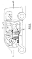
- Figures 1 to 8 show the arrangement of a table retractable 10 into the passenger compartment 12 of a vehicle 14, according to a first embodiment of the invention.
- transverse will be used to qualify a substantially horizontal direction and orthogonal to the longitudinal direction X-X, and to qualify a element contained in a plan generally orthogonal to the longitudinal direction X-X.
- the arrangement comprises a console 16, which is mounted on the floor 18 of the vehicle 14, and which delimits a dwelling, or compartment, for storing the table 10 in position retracted.
- the console 16 forms a box which is delimited, laterally, by two longitudinal vertical walls 20, 22, and at the rear by a transverse wall 24.
- the console 16 has an opening 26 to allow take the table 10 out of its retracted position inside the console 16.
- the opening 26 here comprises a horizontal portion 26h, which is bounded by the upper longitudinal edges 30 of side walls 20, 22, and by the upper transverse edge 32 of the rear transverse wall 24, and it has a portion overall vertical 26v, which is bounded by the edges vertical front 28 of the side walls 20, 22.
- the console 16 has a front cover 34, which is produced here in two parts 36, 38 articulated with respect to each other, and which is pivotally mounted around a lower transverse axis A1, at the lower end of the front portion of the opening 26.
- the lower part 36 of the front cover 34 is designed to close the vertical portion 26v of the opening 26, and the portion upper 38 of the front cover 34 is designed to close a front part of the horizontal portion 26h of the opening 26.
- the upper part 38 is pivotally linked, around a upper transverse axis A2, by its front transverse edge 40, at the upper transverse edge 42 of the lower part 36.
- the console 16 also includes a rear cover 44 which is designed to close a rear part of the horizontal portion 26h of the opening 26.
- the rear cover 44 here has an L-shaped profile, in a plane longitudinal vertical, so that, in its closed position, which is shown in Figure 2, it has, at the rear, a pan transverse 46 and, at the front, a horizontal section 48.
- the rear cover 44 is pivotally mounted around a transverse axis A3, by its rear end transverse edge 50, on the rear transverse wall 24 of the console 16.
- the rear cover 44 is therefore capable of pivoting around its transverse axis A3, between a closed position, shown in particular in Figure 2, and a position opening, shown in particular in Figure 3.
- the rear transverse wall 24 here comprises a recess 52, in its upper part, to receive in a complementary manner the transverse section 46 of the rear cover 44.
- Table 10 is pivotally mounted around a shaft transverse 57, inside the console 16, between the position retracted, which is illustrated in particular in Figure 6 (in lines strong), and a horizontal position of use, which is illustrated in particular by FIGS. 1, 5, and 8.
- the transverse pivot shaft 57 of the table 10 is arranged here in the vicinity of the upper transverse edge 32 of the rear transverse wall 24 of the console 16, that is to say rear and top of console 16.
- Table 10 has two side panels 58, 60, of overall rectangular shape, which are arranged parallel, each in a longitudinal and vertical plane, inside the console 16, in the retracted position.
- the side panels 58, 60 are pivotally linked around of a longitudinal axis A4, by their upper longitudinal edges 62, 64, considering the retracted position. We will call these longitudinal edges 62, 64, pivot edges.
- Table 10 has a hinge 66, ensuring the pivoting of the side panels 58, 60 around the axis longitudinal A4, which is arranged in the vicinity of the rear edge upper of panels 58, 60, and which is pivotally mounted around the shaft 57, so as to allow the pivoting of the panels 58, 60, around the transverse shaft 57, from the retracted position, up and back, up to the position of use.
- edges longitudinal pivot 62, 64 of the side panels 58, 60 generally extend longitudinally forward, from the transverse shaft 57, and in the position of use, the edges longitudinal pivot 62, 64 extend generally longitudinally rearwards, from the transverse shaft 57.
- the rear cover 44 is retained vertically in its position opening by suitable stop means (not shown), so that its transverse end edge before 56 can form a substantially bearing surface horizontal for table 10 in use position.
- the front cover is opened 34 by pivoting it forward, i.e. counterclockwise considering figure 6, around its transverse axis lower A1.
- the upper part is also pivoted 38 of the front cover 34 around the upper transverse axis A2, of so as to free the space in the area of pivoting of the table 10 around the transverse shaft 57.
- Figure 7 represents table 10 in an intermediate position, partially extended from console 16.
- the panels 58, 60 extend substantially vertically towards the high, relative to their longitudinal pivot edges 62, 64, as shown in phantom lines in FIG. 5.
- each side panel 58, 60 it then remains to rotate each side panel 58, 60, around the longitudinal axis A4, towards the sides, so that it describes a quarter turn and it reaches its horizontal position of use, as shown in strong lines on the Figures 5 and 8.
- the front cover 34 is closed on the console 16, which allows in particular a use of the wall upper 38 of console 16 as armrest or as storage area.
- Figures 9 and 10 illustrate a second embodiment of an arrangement according to the invention.
- the principle of deploying the table 10 upwards and backwards, from the retracted position to the position horizontal in use, is generally similar to that of first embodiment.
- the side panels 58, 60 of the table 10 are here pivotally mounted, along the longitudinal axis A4, on the face interior 67 of a central plate 68 which, in the position retracted, closes the horizontal portion 26h of the opening 26 of console 16.
- the front cover 34 has a single part 36 corresponding overall to the lower part of the cover before 34 of the first embodiment, the central plate 68 replacing the upper part 38.
- the console 16 is here without rear cover 44.
- the central plate 68 is here integral with a block 70, by a end portion of its outer face 72.
- the block 70 is mounted pivoting around the shaft 57 of the console 16, and it closes the rear part of the horizontal portion 26h of the opening 26, in retracted position.
- the side panels 58, 60 extend vertically downwards, from the inside 67 of the central plate 68.
- the console 16 also includes a telescopic arm of retractable support 74, which is received in a groove of vertical storage 76, of complementary shape to the arm 74, made in the rear transverse face 24 of the console 16.
- the arm 74 is pivotally mounted around an axis transverse, by its lower end 78.
- the arm has a fitting member 80, which is designed to fit into a complementary housing 82 of the outer face 72 of the plate central 68, when it occupies its position of use.
- the side panels 58, 60 of the table 10 are then deployed by rotating them around the longitudinal axis A4, the same way as in the first embodiment.
- An important advantage of the arrangement according to the invention is that it allows a deployment of the table 10 towards the rear, by compared to console 16 so the console 16 can be arranged between two seats, in the passenger compartment 12 of the vehicle 14.
- the console 16 for storing table 10 does not obstruct an aisle serving a row of seats.
- table 10 is deployed in full overhang backwards, relative to the console 16, which does not no discomfort for users' legs, and this allows close the opening 26, in the position of use, as in the first embodiment, to allow the use of the upper part 38 of the console 16 as an armrest, or as storage space.
- the use of the rear cover 44 as a support element table 10 in use position minimizes the size of the support means of the table 10, in particular compared to the second embodiment.
- each side panel 58, 60 of the table 10 can have a portion of a foldable plate, in the manner of a wallet, in position of use, in order to increase the area of table 10 in a horizontal plane.
Landscapes
- Engineering & Computer Science (AREA)
- Transportation (AREA)
- Mechanical Engineering (AREA)
- Vehicle Step Arrangements And Article Storage (AREA)
- Passenger Equipment (AREA)
Abstract
Description
La présente invention concerne l'agencement d'une table escamotable dans l'habitacle d'un véhicule automobile.The present invention relates to the arrangement of a table retractable into the passenger compartment of a motor vehicle.
L'invention concerne plus particulièrement l'agencement d'une table escamotable dans l'habitacle d'un véhicule automobile, comportant une console qui est montée sur le plancher du véhicule et qui délimite un compartiment pour le rangement de la table en position escamotée, du type dans lequel la table comporte au moins un panneau qui est articulé sur la console, par un bord longitudinal dit de pivotement, autour d'un axe transversal agencé au voisinage d'une extrémité longitudinale du bord de pivotement, qui s'étend globalement dans un plan longitudinal vertical, en position escamotée, et qui s'étend globalement dans un plan horizontal, en position horizontale d'utilisation, du type dans lequel le panneau est monté pivotant autour d'un axe longitudinal agencé au voisinage de son bord longitudinal de pivotement, de manière que le panneau parvienne à sa position d'utilisation, à partir de sa position escamotée, en pivotant, dans un premier temps, vers le haut et vers l'arrière, autour de l'axe transversal et, dans un second temps, vers un côté et vers le bas, autour de l'axe longitudinal, et du type dans lequel la console comporte, globalement dans sa partie supérieure, une ouverture pour le passage du panneau lorsqu'il pivote autour de son axe transversal, et au moins un capot pivotant susceptible de fermer l'ouvertureThe invention relates more particularly to the arrangement a retractable table in the passenger compartment of a vehicle automobile, comprising a console which is mounted on the vehicle floor and which delimits a compartment for the storage of the table in the retracted position, of the type in which the table has at least one panel which is articulated on the console, by a longitudinal edge said to pivot, around a transverse axis arranged in the vicinity of a longitudinal end the pivoting edge, which extends generally in one plane longitudinal vertical, in the retracted position, and which extends generally in a horizontal plane, in a horizontal position of use, of the type in which the panel is pivotally mounted around a longitudinal axis arranged in the vicinity of its edge longitudinal pivot, so that the panel reaches in its position of use, from its retracted position, in initially swiveling upwards and backwards, around the transverse axis and, secondly, towards a side and down, around the longitudinal axis, and of the type in which the console comprises, generally in its part upper, an opening for the passage of the panel when pivots around its transverse axis, and at least one cover swivel capable of closing the opening
Les véhicules ayant un habitacle très modulables du type « monospaces » et les petits véhicules utilitaires pour le transport de passagers, sont de plus en plus employés pour une utilisation « loisirs », en week-end ou en vacances. Ce type d'utilisation a fait apparaítre le besoin de prévoir une table à l'intérieur des véhicules. Cette table doit être escamotable, pour ne pas diminuer l'espace disponible à l'intérieur de l'habitacle du véhicule, lorsque la table n'est pas utilisée. Vehicles with a very modular passenger compartment of the type "Minivans" and small utility vehicles for transport of passengers, are increasingly used for use "Leisure", weekends or holidays. This type of use has highlights the need to provide a table inside vehicles. This table must be retractable, so as not to decrease the space available inside the passenger compartment vehicle, when the table is not in use.
On connaít déjà des véhicules particuliers dans lesquels les dossiers des sièges sont munis de tablettes relevables. De telles tablettes sont toujours de très petites dimensions, de sorte qu'elles ne permettent pas de poser plus de deux gobelets, ou canettes, et qu'elles forment des écritoires symboliques.We already know particular vehicles in which the seat backs are fitted with liftable shelves. Of such shelves are always very small, so do not allow more than two cups to be placed, or cans, and that they form symbolic writing cases.
Dans certains véhicules de loisirs, réalisés sur la base de véhicules utilitaires, il est prévu une table escamotable qui se déploie, soit depuis un garnissage intérieur latéral de l'habitacle, soit depuis une console agencée au centre de l'habitacle.In some recreational vehicles, made on the basis of utility vehicles, a retractable table is provided which deploys, either from a side interior lining of the passenger compartment, either from a console arranged in the center of the passenger compartment.
Lorsque la table se déploie depuis le garnissage intérieur latéral, elle ne peut être utilisée que dans la moitié de l'habitacle correspondante, de sorte que les passagers situés dans l'autre moitié de l'habitacle ne sont pas en mesure d'utiliser la table.When the table deploys from the interior upholstery side, it can only be used in half of the passenger compartment corresponding, so the passengers located in the other half of the passenger compartment are unable to use the table.
Lorsque la table se déploie depuis la console centrale, elle se déplie généralement de chaque côté de la console, de sorte qu'elle peut s'étendre globalement sur toute la largeur de l'habitacle. Cependant, lorsque la table est escamotée dans la console, la console encombre inutilement la partie centrale de l'habitacle.When the table deploys from the center console, it usually folds out on either side of the console, so that it can extend globally over the entire width of the cockpit. However, when the table is folded into the console, the console unnecessarily clutters the central part of the cockpit.
L'invention vise à remédier à ces inconvénients en proposant une solution simple et économique.The invention aims to remedy these drawbacks by offering a simple and economical solution.
Dans ce but, l'invention propose un agencement du type décrit précédemment, caractérisé en ce que la console comporte un élément de capot qui est monté pivotant, par rapport à la console, autour d'un axe sensiblement transversal, entre une position de fermeture et une position d'ouverture de la console, et en ce que, en position d'ouverture, l'élément de capot forme un élément de soutien du panneau dans sa position d'utilisation.To this end, the invention provides an arrangement of the type described above, characterized in that the console comprises a cover element which is pivotally mounted relative to the console, around a substantially transverse axis, between a closed position and an open position of the console, and in that, in the open position, the cover element forms a support element of the panel in its position of use.
Selon d'autres caractéristiques de l'invention :
- le panneau est monté pivotant autour de son axe transversal sur une plaque centrale, et la plaque centrale est montée pivotante autour de l'axe transversal ;
- en position escamotée, la plaque centrale ferme la partie supérieure de l'ouverture de la console ;
- la table comporte deux panneaux qui sont montés pivotant autour du même axe transversal et qui sont articulés l'un par rapport à l'autre.
- the panel is pivotally mounted about its transverse axis on a central plate, and the central plate is pivotally mounted around the transverse axis;
- in the retracted position, the central plate closes the upper part of the console opening;
- the table has two panels which are pivotally mounted about the same transverse axis and which are articulated relative to each other.
D'autres caractéristiques et avantages de l'invention apparaítront à la lecture de la description détaillée qui suit pour la compréhension de laquelle on se reportera aux dessins annexés dans lesquels :
- la figure 1 est une vue de côté avec arrachement qui représente schématiquement l'agencement d'une table escamotable dans un véhicule conformément à un premier mode de réalisation de l'invention ;
- la figure 2 est une vue en perspective de trois-quarts arrière qui représente schématiquement une console de rangement de la table de la figure 1 en position escamotée et fermée ;
- la figure 3 est une vue similaire à celle de la figure 2 qui représente schématiquement la table de la figure 1 partiellement sortie de la console et les capots de la console en positions ouvertes ;
- la figure 4 est une vue similaire à celle de la figure 2 qui représente la table de la figure 1 avec un panneau en position d'utilisation, le capot avant de la console étant fermé ;
- la figure 5 est une vue arrière qui représente schématiquement la table de la figure 1 en position d'utilisation ;
- la figure 6 est une vue de côté qui illustre schématiquement les différentes positions occupées par la table de la figure 1 lors de son pivotement entre sa position escamotée et sa position d'utilisation ;
- la figure 7 est une vue similaire à celle de la figure 6 qui représente la table de la figure 1 dans la même position qu'à la figure 3 ;
- la figure 8 est une vue similaire à celle de la figure 6 qui représente la table en position d'utilisation, le capot avant de la console étant fermé ;
- la figure 9 est une similaire à celle de la figure 2 qui représente schématiquement un agencement selon un deuxième mode de réalisation de l'invention en position escamotée ;
- la figure 10 est une vue similaire à celle de la figure 4 qui représente la table de la figure 9 en position d'utilisation.
- Figure 1 is a side view with cutaway which schematically shows the arrangement of a retractable table in a vehicle according to a first embodiment of the invention;
- Figure 2 is a rear three-quarter perspective view which schematically shows a storage console of the table of Figure 1 in the retracted and closed position;
- Figure 3 is a view similar to that of Figure 2 which schematically shows the table of Figure 1 partially extended from the console and the console covers in open positions;
- Figure 4 is a view similar to that of Figure 2 which shows the table of Figure 1 with a panel in the use position, the front cover of the console being closed;
- Figure 5 is a rear view which schematically shows the table of Figure 1 in the position of use;
- Figure 6 is a side view which schematically illustrates the different positions occupied by the table of Figure 1 during its pivoting between its retracted position and its position of use;
- Figure 7 is a view similar to that of Figure 6 which shows the table of Figure 1 in the same position as in Figure 3;
- Figure 8 is a view similar to that of Figure 6 which shows the table in the use position, the front cover of the console being closed;
- Figure 9 is a similar to that of Figure 2 which schematically shows an arrangement according to a second embodiment of the invention in the retracted position;
- Figure 10 is a view similar to that of Figure 4 which shows the table of Figure 9 in the position of use.
Dans la suite de la description, des éléments identiques ou similaires seront désignés par les mêmes références.In the following description, identical elements or similar will be designated by the same references.
Les figures 1 à 8 représentent l'agencement d'une table
escamotable 10 dans l'habitacle 12 d'un véhicule 14, selon un
premier mode de réalisation de l'invention.Figures 1 to 8 show the arrangement of a table
retractable 10 into the
Pour la suite de la description, on définit, à titre non limitatif, une direction longitudinale horizontale X-X, qui correspond à l'axe longitudinal du véhicule. A titre non limitatif, on utilisera une orientation de l'arrière vers l'avant, suivant la direction longitudinale X-X, qui correspond à une orientation de la droite vers la gauche, en considérant la figure 1.For the remainder of the description, limiting, a horizontal longitudinal direction X-X, which corresponds to the longitudinal axis of the vehicle. Without limitation, we will use an orientation from back to front, following the longitudinal direction X-X, which corresponds to an orientation of the right to left, considering Figure 1.
A titre non limitatif, on utilisera le terme « transversal » pour qualifier une direction sensiblement horizontale et orthogonale à la direction longitudinale X-X, et pour qualifier un élément contenu dans un plan globalement orthogonal à la direction longitudinale X-X.Without limitation, the term "transverse" will be used to qualify a substantially horizontal direction and orthogonal to the longitudinal direction X-X, and to qualify a element contained in a plan generally orthogonal to the longitudinal direction X-X.
L'agencement comporte une console 16, qui est montée
sur le plancher 18 du véhicule 14, et qui délimite un logement, ou
compartiment, pour le rangement de la table 10 en position
escamotée.The arrangement comprises a
Comme on peut le voir notamment sur les figures 2 et 3, la
console 16 forme un caisson qui est délimité, latéralement, par
deux parois verticales longitudinales 20, 22, et à l'arrière par une
paroi transversale 24.As can be seen in particular in FIGS. 2 and 3, the
La console 16 comporte une ouverture 26 pour permettre
de sortir la table 10 de sa position escamotée à l'intérieur de la
console 16.The
L'ouverture 26 comporte ici une portion horizontale 26h,
qui est délimitée par les bords longitudinaux supérieurs 30 des
parois latérales 20, 22, et par le bord transversal supérieur 32 de
la paroi transversale arrière 24, et elle comporte une portion
globalement verticale 26v, qui est délimitée par les bords
verticaux avant 28 des parois latérales 20, 22.The
La console 16 comporte un capot avant 34, qui est réalisé
ici en deux parties 36, 38 articulées l'une par rapport à l'autre, et
qui est monté à pivotement, autour d'un axe transversal inférieur
A1, à l'extrémité inférieure de la portion avant de l'ouverture 26.The
La partie inférieure 36 du capot avant 34 est conçue pour
fermer la portion verticale 26v de l'ouverture 26, et la partie
supérieure 38 du capot avant 34 est conçue pour fermer une
partie avant de la portion horizontale 26h de l'ouverture 26.The
La partie supérieure 38 est liée à pivotement, autour d'un
axe transversal supérieur A2, par son bord transversal avant 40,
au bord transversal supérieur 42 de la partie inférieure 36.The
La console 16 comporte aussi un capot arrière 44 qui est
conçu pour fermer une partie arrière de la portion horizontale 26h
de l'ouverture 26.The
Le capot arrière 44 a ici un profil en L, dans un plan
longitudinal vertical, de sorte que, dans sa position de fermeture,
qui est représentée sur la figure 2, il comporte, à l'arrière, un pan
transversal 46 et, à l'avant, un pan horizontal 48.The
Le capot arrière 44 est monté à pivotement, autour d'un
axe transversal A3, par son bord transversal d'extrémité arrière
50, sur la paroi transversale arrière 24 de la console 16.The
Le capot arrière 44 est donc susceptible de pivoter autour
de son axe transversal A3, entre une position de fermeture,
représentée notamment sur la figure 2, et une position
d'ouverture, représentée notamment sur la figure 3.The
La paroi transversale arrière 24 comporte ici un
décrochement 52, dans sa partie supérieure, pour recevoir de
manière complémentaire le pan transversal 46 du capot arrière
44. The rear
Dans la position de fermeture des deux capots 34, 44, qui
est représentée sur la figure 2, le bord transversal d'extrémité
arrière 54 de la partie supérieure 38 du capot avant 34 est
adjacent au bord transversal d'extrémité avant 56, en vis-à-vis, du
capot arrière 44.In the closed position of the two
La table 10 est montée à pivotement autour d'un arbre
transversal 57, à l'intérieur de la console 16, entre la position
escamotée, qui est illustrée notamment par la figure 6 (en traits
forts), et une position horizontale d'utilisation, qui est illustrée
notamment par les figures 1, 5, et 8.Table 10 is pivotally mounted around a shaft
transverse 57, inside the
L'arbre transversal de pivotement 57 de la table 10 est
agencé ici au voisinage du bord transversal supérieur 32 de la
paroi transversale arrière 24 de la console 16, c'est à dire à
l'arrière et en haut de la console 16.The
La table 10 comporte deux panneaux latéraux 58, 60, de
forme globalement rectangulaire, qui sont rangés parallèlement,
chacun dans un plan longitudinal et vertical, à l'intérieur de la
console 16, en position escamotée.Table 10 has two
Les panneaux latéraux 58, 60 sont liés à pivotement autour
d'un axe longitudinal A4, par leurs bords longitudinaux supérieurs
62, 64, en considérant la position escamotée. On appellera ces
bords longitudinaux 62, 64, bords de pivotement.The
La table 10 comporte une charnière 66, assurant le
pivotement des panneaux latéraux 58, 60 autour de l'axe
longitudinal A4, qui est agencée au voisinage de l'arête arrière
supérieure des panneaux 58, 60, et qui est montée à pivotement
autour de l'arbre 57, de manière à permettre le pivotement des
panneaux 58, 60, autour de l'arbre transversal 57, depuis la
position escamotée, vers le haut et vers l'arrière, jusqu'à la
position d'utilisation.Table 10 has a
On note que, dans la position escamotée, les bords
longitudinaux de pivotement 62, 64 des panneaux latéraux 58, 60
s'étendent globalement longitudinalement vers l'avant, depuis
l'arbre transversal 57, et dans la position d'utilisation, les bords
longitudinaux de pivotement 62, 64 s'étendent globalement
longitudinalement vers l'arrière, depuis l'arbre transversal 57.Note that, in the retracted position, the edges
Avantageusement, selon le mode de réalisation représenté
ici, le capot arrière 44 est retenu verticalement dans sa position
d'ouverture par des moyens de butée appropriés (non
représentés), de manière que son bord transversal d'extrémité
avant 56 puisse former une surface d'appui sensiblement
horizontale pour la table 10 en position d'utilisation.Advantageously, according to the embodiment shown
here, the
On décrit maintenant le fonctionnement de l'agencement selon le premier mode de réalisation de l'invention, en référence notamment aux figures 4 à 8.We now describe the operation of the arrangement according to the first embodiment of the invention, with reference especially in Figures 4 to 8.
A partir de la position escamotée, on ouvre le capot avant 34 en le faisant pivoter vers l'avant, c'est à dire dans le sens anti-horaire en considérant la figure 6, autour de son axe transversal inférieur A1.From the retracted position, the front cover is opened 34 by pivoting it forward, i.e. counterclockwise considering figure 6, around its transverse axis lower A1.
Avantageusement, on fait aussi pivoter la partie supérieure
38 du capot avant 34 autour de l'axe transversal supérieur A2, de
manière à dégager au maximum l'espace dans la zone de
pivotement de la table 10 autour de l'arbre transversal 57.Advantageously, the upper part is also pivoted
38 of the
On fait aussi pivoter le capot arrière 44 vers l'arrière, c'est
à dire dans le sens horaire en considérant la figure 6, autour de
son axe transversal A3, jusqu'à ce que le capot arrière 44 occupe
sa position d'ouverture déterminée par les moyens de butée.We also rotate the
L'ouverture 26 de la console 16 étant dégagée, on sort la
table 10 en la faisant pivoter autour de l'arbre transversal 57,
dans le sens horaire en considérant la figure 6. La figure 7
représente la table 10 dans une position intermédiaire,
partiellement sortie de la console 16.The
On fait pivoter la table 10 jusqu'à la position d'utilisation,
c'est à dire jusqu'à ce que les bords longitudinaux de pivotement
62, 64 des panneaux latéraux 58, 60 s'étendent longitudinalement
vers l'arrière, depuis l'arbre 57, de manière qu'ils soient en appui
vers le bas sur le bord transversal d'extrémité 56 du capot arrière
44. We rotate the table 10 to the position of use,
i.e. until the longitudinal pivot edges
62, 64 of the
A ce stade du déploiement de la table 10, les panneaux
latéraux 58, 60 s'étendent sensiblement verticalement vers le
haut, par rapport à leurs bords longitudinaux de pivotement 62,
64, comme on l'a représenté en traits fantômes sur la figure 5.At this stage of the deployment of table 10, the
Il reste alors à faire pivoter chaque panneau latéral 58, 60,
autour de l'axe longitudinal A4, vers les côtés, de manière qu'il
décrive un quart de tour et qu'il atteigne sa position horizontale
d'utilisation, comme on l'a représenté en traits forts sur les
figures 5 et 8.It then remains to rotate each
De préférence, lorsque la table 10 occupe sa position
finale d'utilisation, le capot avant 34 est refermé sur la console
16, ce qui permet notamment une utilisation de la paroi
supérieure 38 de la console 16 comme accoudoir ou comme
surface de rangement.Preferably, when the table 10 occupies its position
end of use, the
Pour replacer la table 10 dans sa position escamotée, il suffit d'effectuer les étapes décrites précédemment dans un ordre inversé.To return the table 10 to its retracted position, it just perform the steps described above in order reversed.
Les figures 9 et 10 illustrent un second mode de réalisation d'un agencement selon l'invention.Figures 9 and 10 illustrate a second embodiment of an arrangement according to the invention.
Le principe du déploiement de la table 10 vers le haut et vers l'arrière, depuis la position escamotée jusqu'à la position horizontale d'utilisation, est globalement similaire à celui du premier mode de réalisation.The principle of deploying the table 10 upwards and backwards, from the retracted position to the position horizontal in use, is generally similar to that of first embodiment.
Les panneaux latéraux 58, 60 de la table 10 sont ici
montés à pivotement, suivant l'axe longitudinal A4, sur la face
intérieure 67 d'une plaque centrale 68 qui, dans la position
escamotée, ferme la portion horizontale 26h de l'ouverture 26 de
la console 16.The
On note que le capot avant 34 comporte une seule partie
36 correspondant globalement à la partie inférieure du capot
avant 34 du premier mode de réalisation, la plaque centrale 68
remplaçant la partie supérieure 38. De plus, la console 16 est ici
dépourvue de capot arrière 44. Note that the
La plaque centrale 68 est ici solidaire d'un bloc 70, par une
portion d'extrémité de sa face extérieure 72. Le bloc 70 est monté
à pivotement autour de l'arbre 57 de la console 16, et il ferme la
partie arrière de la portion horizontale 26h de l'ouverture 26, en
position escamotée.The
En position escamotée, les panneaux latéraux 58, 60
s'étendent verticalement vers le bas, depuis la face intérieure 67
de la plaque centrale 68.In the retracted position, the
La console 16 comporte aussi un bras télescopique de
soutien 74 escamotable, qui est reçu dans une rainure de
rangement verticale 76, de forme complémentaire du bras 74,
réalisée dans la face transversale arrière 24 de la console 16.The
Le bras 74 est monté à pivotement autour d'un axe
transversal, par son extrémité inférieure 78.The
A son extrémité libre supérieure, le bras comporte un
organe d'emboítement 80, qui est prévu pour s'emboíter dans un
logement complémentaire 82 de la face extérieure 72 de la plaque
centrale 68, lorsque celle-ci occupe sa position d'utilisation.At its upper free end, the arm has a
Le déploiement de la table 10 selon le deuxième mode de réalisation s'effectue de la manière suivante.The deployment of table 10 according to the second mode of realization is carried out as follows.
Après avoir ouvert le capot avant 34, on fait basculer la
plaque centrale 68 d'un demi tour vers l'arrière, autour de l'arbre
transversal 57, dans le sens horaire en considérant la figure 9.After opening the
Lorsque la plaque centrale 68 occupe sa position
horizontale d'utilisation, en porte à faux vers l'arrière, on fait
pivoter le bras 74 autour de son axe, dans le sens horaire, et on
emboíte l'extrémité 80 dans le logement 82 de la plaque centrale
68, de manière que le bras 74 forme un arc-boutant pour soutenir
verticalement la plaque centrale 68 dans sa position d'utilisation.When the
Les panneaux latéraux 58, 60 de la table 10 sont ensuite
déployés en les faisant pivoter autour de l'axe longitudinal A4, de
la même manière que dans le premier mode de réalisation.The
Un avantage important de l'agencement selon l'invention
est qu'il permet un déploiement de la table 10 vers l'arrière, par
rapport à la console 16, de sorte que la console 16 peut être
agencée entre deux sièges, dans l'habitacle 12 du véhicule 14.
Ainsi, contrairement à certains dispositifs connus, la console 16
de rangement de la table 10 n'encombre pas une allée desservant
une rangée de sièges.An important advantage of the arrangement according to the invention
is that it allows a deployment of the table 10 towards the rear, by
compared to console 16 so the
On note que la table 10 se déploie en porte-à-faux complet
vers l'arrière, par rapport à la console 16, ce qui n'entraíne
aucune gêne pour les jambes des usagers, et ce qui permet de
refermer l'ouverture 26, en position d'utilisation, comme dans le
premier mode de réalisation, pour permettre l'utilisation de la
partie supérieure 38 de la console 16 comme accoudoir, ou
comme surface de rangement.Note that table 10 is deployed in full overhang
backwards, relative to the
L'utilisation du capot arrière 44 comme élément de soutien
de la table 10 en position d'utilisation permet de minimiser
l'encombrement des moyens de soutien de la table 10, notamment
par rapport au deuxième mode de réalisation.The use of the
Selon une variante de réalisation (non représentée) de
l'invention, chaque panneau latéral 58, 60 de la table 10 peut
comporter une portion de plaque dépliable, à la manière d'un
portefeuille, en position d'utilisation, en vue d'augmenter l'aire de
la table 10 dans un plan horizontal.According to an alternative embodiment (not shown) of
the invention, each
Claims (4)
caractérisé en ce que la console (16) comporte un élément de capot (44) qui est monté pivotant, par rapport à la console (16), autour d'un axe sensiblement transversal (A3), entre une position de fermeture et une position d'ouverture de la console (16), et en ce que, en position d'ouverture, l'élément de capot (44) forme un élément de soutien du panneau (58, 60) dans sa position d'utilisation.Arrangement of a retractable table (10) in the passenger compartment (12) of a motor vehicle (14), comprising a console (16) which is mounted on the floor (18) of the vehicle (14) and which delimits a compartment for storing the table (10) in the retracted position, of the type in which the table (10) comprises at least one panel (58, 60) which is articulated on the console (16), by a longitudinal edge called the pivoting ( 62, 64), around a transverse axis (57) arranged in the vicinity of a longitudinal end of the pivoting edge (62, 64), which extends generally in a vertical longitudinal plane, in the retracted position, and which s 'generally extends in a horizontal plane, in a horizontal position of use, of the type in which the panel (58, 60) is pivotally mounted about a longitudinal axis (A4) arranged in the vicinity of its longitudinal pivot edge (62, 64), so that the panel (58, 60) reaches its position of use, from its retracted position ée, by pivoting, firstly, upwards and backwards, around the transverse axis (57) and, secondly, towards one side and downwards, around the longitudinal axis ( A4), and of the type in which the console (16) has, generally in its upper part, an opening (26) for the passage of the panel (58, 60) when it pivots around its transverse axis (57), and at least one pivoting cover (34, 44) capable of closing the opening (26),
characterized in that the console (16) has a cover element (44) which is pivotally mounted, relative to the console (16), about a substantially transverse axis (A3), between a closed position and a position opening the console (16), and in that , in the open position, the cover element (44) forms a support element for the panel (58, 60) in its position of use.
Applications Claiming Priority (2)
| Application Number | Priority Date | Filing Date | Title |
|---|---|---|---|
| FR0212254A FR2845327B1 (en) | 2002-10-03 | 2002-10-03 | IMPROVED ARRANGEMENT OF A RETRACTABLE TABLE IN THE HABITACLE OF A MOTOR VEHICLE |
| FR0212254 | 2002-10-03 |
Publications (3)
| Publication Number | Publication Date |
|---|---|
| EP1405758A2 true EP1405758A2 (en) | 2004-04-07 |
| EP1405758A3 EP1405758A3 (en) | 2004-05-19 |
| EP1405758B1 EP1405758B1 (en) | 2006-09-20 |
Family
ID=31985418
Family Applications (1)
| Application Number | Title | Priority Date | Filing Date |
|---|---|---|---|
| EP20030103658 Expired - Lifetime EP1405758B1 (en) | 2002-10-03 | 2003-10-02 | Improved folding table arrangement in an automotive vehicle passenger compartment |
Country Status (3)
| Country | Link |
|---|---|
| EP (1) | EP1405758B1 (en) |
| DE (1) | DE60308461T2 (en) |
| FR (1) | FR2845327B1 (en) |
Cited By (13)
| Publication number | Priority date | Publication date | Assignee | Title |
|---|---|---|---|---|
| FR2910402A1 (en) * | 2006-12-22 | 2008-06-27 | Renault Sas | Console for e.g. monospace motor vehicle, has cover in two plane parts which are mounted on rods, where rods have height to bring two parts above compartment in deployed position in which parts form table |
| DE102012108206A1 (en) | 2011-09-13 | 2013-03-14 | Naber Holding Gmbh & Co. Kg | Installation vibrating table |
| JP2014510670A (en) * | 2011-04-01 | 2014-05-01 | ゾディアック シーツ ユーケー リミティッド | Aircraft seating arrangement with table |
| FR3012386A1 (en) * | 2013-10-31 | 2015-05-01 | Peugeot Citroen Automobiles Sa | ARRANGEMENT OF A CONSOLE HAVING MECHANICALLY TABLE-CONVERTIBLE ELEMENTS IN THE CABIN OF A VEHICLE |
| DE102017002003A1 (en) | 2017-03-01 | 2017-10-19 | Daimler Ag | Stowage device for an interior of a vehicle, in particular a passenger car |
| US10059296B2 (en) * | 2016-03-14 | 2018-08-28 | Ford Global Technologies, Llc | Vehicle table with deployable airbag |
| WO2018228748A1 (en) * | 2017-06-16 | 2018-12-20 | Brose Fahrzeugteile Gmbh & Co. Kommanditgesellschaft, Coburg | Collapsible stowage furniture item for a motor vehicle |
| USD846277S1 (en) | 2016-10-17 | 2019-04-23 | Leah Tillery | Combined carrying case and tray |
| DE102013006482B4 (en) | 2013-04-15 | 2019-06-13 | Audi Ag | Pivoting device for a fitting part of a vehicle |
| US10414313B2 (en) | 2016-02-26 | 2019-09-17 | Ford Global Technologies, Llc | Hidden foldable tray table |
| US10486572B2 (en) | 2016-06-10 | 2019-11-26 | James Smythe | Portable, tray and carrying case apparatus |
| CN111204269A (en) * | 2020-01-22 | 2020-05-29 | 米司特(大连)工业控制系统有限公司 | Folding table special for control console |
| US10717358B2 (en) * | 2018-08-24 | 2020-07-21 | Ford Global Technologies, Llc | Configurable vehicle console |
Families Citing this family (6)
| Publication number | Priority date | Publication date | Assignee | Title |
|---|---|---|---|---|
| FR2898090B1 (en) | 2006-03-02 | 2009-02-13 | Renault Sas | ARRANGEMENT OF A RETRACTABLE SHELF IN THE TRIM OF A MOTOR VEHICLE |
| FR2912358A1 (en) * | 2007-02-13 | 2008-08-15 | Renault Sas | Console and foldable table assembly for motor vehicle, has foldable board movable between turned-down position against surface of board support and horizontal position when support is in stand up position |
| DE102007050967B4 (en) | 2007-10-23 | 2012-12-06 | Grammer Ag | Seat with extendable table |
| FR3002891B1 (en) * | 2013-03-05 | 2015-02-27 | Peugeot Citroen Automobiles Sa | ARRANGEMENT OF A CONSOLE HAVING TABLE CONVERTIBLE ELEMENTS IN THE CABIN OF A VEHICLE |
| FR3054981B1 (en) * | 2016-08-11 | 2018-08-24 | Peugeot Citroen Automobiles Sa | CONSOLE FOR A MOTOR VEHICLE HAVING A CONVERTIBLE TABLE CONTAINABLE AND ROTATING BY A VERIN. |
| DE102017211229B4 (en) * | 2017-06-30 | 2024-01-04 | Bayerische Motoren Werke Aktiengesellschaft | Table device for the interior of a motor vehicle |
Citations (6)
| Publication number | Priority date | Publication date | Assignee | Title |
|---|---|---|---|---|
| GB620861A (en) * | 1947-01-27 | 1949-03-31 | British Overseas Airways Corp | Improvements in adjustable tables and bookrests for use with chairs and the like |
| US2947348A (en) * | 1958-08-01 | 1960-08-02 | L B Smith Aircraft Corp | Arm rest and concealed table unit |
| US3632161A (en) * | 1970-07-13 | 1972-01-04 | Universal Oil Prod Co | Side arm stowable table |
| US4852940A (en) * | 1987-08-20 | 1989-08-01 | Weber Aircraft Corporation | Stowable table system |
| US4944552A (en) * | 1989-03-17 | 1990-07-31 | Weber Aircraft, Inc. | Stowable table system |
| US6347590B1 (en) * | 1999-02-27 | 2002-02-19 | Lear Corporation | Center console stored extensible tray table |
-
2002
- 2002-10-03 FR FR0212254A patent/FR2845327B1/en not_active Expired - Fee Related
-
2003
- 2003-10-02 DE DE2003608461 patent/DE60308461T2/en not_active Expired - Lifetime
- 2003-10-02 EP EP20030103658 patent/EP1405758B1/en not_active Expired - Lifetime
Patent Citations (6)
| Publication number | Priority date | Publication date | Assignee | Title |
|---|---|---|---|---|
| GB620861A (en) * | 1947-01-27 | 1949-03-31 | British Overseas Airways Corp | Improvements in adjustable tables and bookrests for use with chairs and the like |
| US2947348A (en) * | 1958-08-01 | 1960-08-02 | L B Smith Aircraft Corp | Arm rest and concealed table unit |
| US3632161A (en) * | 1970-07-13 | 1972-01-04 | Universal Oil Prod Co | Side arm stowable table |
| US4852940A (en) * | 1987-08-20 | 1989-08-01 | Weber Aircraft Corporation | Stowable table system |
| US4944552A (en) * | 1989-03-17 | 1990-07-31 | Weber Aircraft, Inc. | Stowable table system |
| US6347590B1 (en) * | 1999-02-27 | 2002-02-19 | Lear Corporation | Center console stored extensible tray table |
Cited By (16)
| Publication number | Priority date | Publication date | Assignee | Title |
|---|---|---|---|---|
| FR2910402A1 (en) * | 2006-12-22 | 2008-06-27 | Renault Sas | Console for e.g. monospace motor vehicle, has cover in two plane parts which are mounted on rods, where rods have height to bring two parts above compartment in deployed position in which parts form table |
| JP2014510670A (en) * | 2011-04-01 | 2014-05-01 | ゾディアック シーツ ユーケー リミティッド | Aircraft seating arrangement with table |
| US9382007B2 (en) | 2011-04-01 | 2016-07-05 | Zodiac Seats Uk Limited | Aircraft seat arrangement including table |
| DE102012108206A1 (en) | 2011-09-13 | 2013-03-14 | Naber Holding Gmbh & Co. Kg | Installation vibrating table |
| EP2570046A2 (en) | 2011-09-13 | 2013-03-20 | Naber Holding GmbH & Co. KG | Built in pivoting table |
| DE102013006482B4 (en) | 2013-04-15 | 2019-06-13 | Audi Ag | Pivoting device for a fitting part of a vehicle |
| FR3012386A1 (en) * | 2013-10-31 | 2015-05-01 | Peugeot Citroen Automobiles Sa | ARRANGEMENT OF A CONSOLE HAVING MECHANICALLY TABLE-CONVERTIBLE ELEMENTS IN THE CABIN OF A VEHICLE |
| WO2015063412A1 (en) * | 2013-10-31 | 2015-05-07 | Peugeot Citroen Automobiles Sa | Arrangement of a console having elements that can be mechanically convertible into a table in the interior of a vehicle |
| US10414313B2 (en) | 2016-02-26 | 2019-09-17 | Ford Global Technologies, Llc | Hidden foldable tray table |
| US10059296B2 (en) * | 2016-03-14 | 2018-08-28 | Ford Global Technologies, Llc | Vehicle table with deployable airbag |
| US10486572B2 (en) | 2016-06-10 | 2019-11-26 | James Smythe | Portable, tray and carrying case apparatus |
| USD846277S1 (en) | 2016-10-17 | 2019-04-23 | Leah Tillery | Combined carrying case and tray |
| DE102017002003A1 (en) | 2017-03-01 | 2017-10-19 | Daimler Ag | Stowage device for an interior of a vehicle, in particular a passenger car |
| WO2018228748A1 (en) * | 2017-06-16 | 2018-12-20 | Brose Fahrzeugteile Gmbh & Co. Kommanditgesellschaft, Coburg | Collapsible stowage furniture item for a motor vehicle |
| US10717358B2 (en) * | 2018-08-24 | 2020-07-21 | Ford Global Technologies, Llc | Configurable vehicle console |
| CN111204269A (en) * | 2020-01-22 | 2020-05-29 | 米司特(大连)工业控制系统有限公司 | Folding table special for control console |
Also Published As
| Publication number | Publication date |
|---|---|
| DE60308461D1 (en) | 2006-11-02 |
| FR2845327B1 (en) | 2005-07-22 |
| FR2845327A1 (en) | 2004-04-09 |
| DE60308461T2 (en) | 2007-09-13 |
| EP1405758B1 (en) | 2006-09-20 |
| EP1405758A3 (en) | 2004-05-19 |
Similar Documents
| Publication | Publication Date | Title |
|---|---|---|
| EP1405758B1 (en) | Improved folding table arrangement in an automotive vehicle passenger compartment | |
| FR2853868A1 (en) | Open vehicle rear deck retracting system, has stopper integrated to central board to control deployment of two lateral dashboards with respect to central dashboard, when retractable roof is in arranged position | |
| FR2844230A1 (en) | Stowage container for motor vehicle has side and upper panel hinged to folding rear seats | |
| FR2890611A1 (en) | Modular vehicle seat arrangement comprises pivoting systems which allow seat to be rotated so that it rests on side of seat cushion and back and moved back into boot so that top of back rests against side of seat in front | |
| FR2967110A1 (en) | Transverse partition for separating driver's cabin of commercial vehicle and rear cargo space, has fixed panel moving from closed to release positions to cause deployment of storage behind fixed panel and between movable and fixed panels | |
| FR2761309A1 (en) | Occasional seat for motor vehicles, e.g. pickup trucks | |
| EP1493358B1 (en) | Storage system for a foldable chair | |
| FR2849630A1 (en) | Vehicle for transporting passenger and cargo, has seat to take normal position to receive passenger, and folded back position to store objects in rear part that has platform slidingly mounted in loading position | |
| FR2898090A1 (en) | Retractable table`s fitting for e.g. minivan`s passenger compartment, has rails extending above opening of enclosure when table is in top position, and spring moving table towards top position when user exerts pressure on table`s upper part | |
| EP1211128B1 (en) | Arrangement of seats for a motor vehicle | |
| EP1726474A2 (en) | Foldable seat for motor vehicle and corresponding vehicle | |
| EP1588896B1 (en) | Trunk covering for a vehicle | |
| EP1405759A2 (en) | Foldable table arrangement in an automotive vehicle passenger compartment | |
| FR2964616A1 (en) | Retractable canopy for covering loading space of rear boot in rear structure of stretched motor vehicle, has shins interposed between floor and base walls when apron is in retracted position, to maintain floor wall remote from base wall | |
| FR2948103A1 (en) | Foldable receptacle for use in passenger compartment of transport unit i.e. motor vehicle, has movable receiving part moving with respect to fixed part, where fixed part is entirely placed in movable receiving part in folded up position | |
| FR2889133A1 (en) | Modular arrangement for car trunk has hinged panel that can be set vertically to form a partition between two compartments | |
| FR2885572A1 (en) | Motor vehicle floor unit for passenger compartment, has panels articulated around horizontal axis between folded and deployed positions for being superposed and delimiting flat surface forming continuous floor part | |
| FR2834949A1 (en) | REAR SHELF FOR MOTOR VEHICLE WITH FOLDABLE ROOF | |
| FR2910402A1 (en) | Console for e.g. monospace motor vehicle, has cover in two plane parts which are mounted on rods, where rods have height to bring two parts above compartment in deployed position in which parts form table | |
| FR2857626A1 (en) | Vehicle with modular opening roof comprises several rigid parts and roof support frame carrying roof parts movement mechanism enabling parts to be deployed frontward or retracted vertically behind seats | |
| FR2943018A1 (en) | Interior installation system for motor vehicle i.e. utility vehicle, has structure mounted in vehicle around vertical axis from its utilization position to storing position in which seat occupies position back with rear route of fixed seat | |
| FR3129117A1 (en) | Vehicle fitted with a modular glove box | |
| FR2898845A1 (en) | Luggage cover for boot of motor vehicle, has shelf rotatably mounted to one of ends of roller, and guide edge extending according to direction of deployment in order to guide curtain when it is in deployed position | |
| EP4257428A1 (en) | Habitable motor vehicle with five sitting places provided with a table | |
| FR2845964A1 (en) | Motor vehicle includes rear housing that is longitudinally slidable between a front retracted position and a rear extended position to convert vehicle between a pick-up type vehicle and an estate type vehicle |
Legal Events
| Date | Code | Title | Description |
|---|---|---|---|
| PUAI | Public reference made under article 153(3) epc to a published international application that has entered the european phase |
Free format text: ORIGINAL CODE: 0009012 |
|
| PUAL | Search report despatched |
Free format text: ORIGINAL CODE: 0009013 |
|
| AK | Designated contracting states |
Kind code of ref document: A2 Designated state(s): AT BE BG CH CY CZ DE DK EE ES FI FR GB GR HU IE IT LI LU MC NL PT RO SE SI SK TR |
|
| AX | Request for extension of the european patent |
Extension state: AL LT LV MK |
|
| AK | Designated contracting states |
Kind code of ref document: A3 Designated state(s): AT BE BG CH CY CZ DE DK EE ES FI FR GB GR HU IE IT LI LU MC NL PT RO SE SI SK TR |
|
| AX | Request for extension of the european patent |
Extension state: AL LT LV MK |
|
| 17P | Request for examination filed |
Effective date: 20040917 |
|
| AKX | Designation fees paid |
Designated state(s): DE ES FR GB |
|
| 17Q | First examination report despatched |
Effective date: 20050517 |
|
| GRAP | Despatch of communication of intention to grant a patent |
Free format text: ORIGINAL CODE: EPIDOSNIGR1 |
|
| GRAS | Grant fee paid |
Free format text: ORIGINAL CODE: EPIDOSNIGR3 |
|
| GRAA | (expected) grant |
Free format text: ORIGINAL CODE: 0009210 |
|
| AK | Designated contracting states |
Kind code of ref document: B1 Designated state(s): DE ES FR GB |
|
| REG | Reference to a national code |
Ref country code: GB Ref legal event code: FG4D Free format text: NOT ENGLISH |
|
| GBT | Gb: translation of ep patent filed (gb section 77(6)(a)/1977) |
Effective date: 20061005 |
|
| REF | Corresponds to: |
Ref document number: 60308461 Country of ref document: DE Date of ref document: 20061102 Kind code of ref document: P |
|
| PG25 | Lapsed in a contracting state [announced via postgrant information from national office to epo] |
Ref country code: ES Free format text: LAPSE BECAUSE OF FAILURE TO SUBMIT A TRANSLATION OF THE DESCRIPTION OR TO PAY THE FEE WITHIN THE PRESCRIBED TIME-LIMIT Effective date: 20061231 |
|
| PLBE | No opposition filed within time limit |
Free format text: ORIGINAL CODE: 0009261 |
|
| STAA | Information on the status of an ep patent application or granted ep patent |
Free format text: STATUS: NO OPPOSITION FILED WITHIN TIME LIMIT |
|
| 26N | No opposition filed |
Effective date: 20070621 |
|
| REG | Reference to a national code |
Ref country code: FR Ref legal event code: ST Effective date: 20070831 |
|
| PG25 | Lapsed in a contracting state [announced via postgrant information from national office to epo] |
Ref country code: FR Free format text: LAPSE BECAUSE OF NON-PAYMENT OF DUE FEES Effective date: 20061031 |
|
| PGFP | Annual fee paid to national office [announced via postgrant information from national office to epo] |
Ref country code: GB Payment date: 20090930 Year of fee payment: 7 |
|
| PGFP | Annual fee paid to national office [announced via postgrant information from national office to epo] |
Ref country code: DE Payment date: 20090923 Year of fee payment: 7 |
|
| GBPC | Gb: european patent ceased through non-payment of renewal fee |
Effective date: 20101002 |
|
| PG25 | Lapsed in a contracting state [announced via postgrant information from national office to epo] |
Ref country code: GB Free format text: LAPSE BECAUSE OF NON-PAYMENT OF DUE FEES Effective date: 20101002 |
|
| REG | Reference to a national code |
Ref country code: DE Ref legal event code: R119 Ref document number: 60308461 Country of ref document: DE Effective date: 20110502 |
|
| PG25 | Lapsed in a contracting state [announced via postgrant information from national office to epo] |
Ref country code: DE Free format text: LAPSE BECAUSE OF NON-PAYMENT OF DUE FEES Effective date: 20110502 |