EP1405696B1 - Pulley assembly for the belt of a notching machine - Google Patents
Pulley assembly for the belt of a notching machine Download PDFInfo
- Publication number
- EP1405696B1 EP1405696B1 EP03425644A EP03425644A EP1405696B1 EP 1405696 B1 EP1405696 B1 EP 1405696B1 EP 03425644 A EP03425644 A EP 03425644A EP 03425644 A EP03425644 A EP 03425644A EP 1405696 B1 EP1405696 B1 EP 1405696B1
- Authority
- EP
- European Patent Office
- Prior art keywords
- centre
- counter
- shaping pulley
- shaping
- pulley assembly
- Prior art date
- Legal status (The legal status is an assumption and is not a legal conclusion. Google has not performed a legal analysis and makes no representation as to the accuracy of the status listed.)
- Expired - Lifetime
Links
- 238000007493 shaping process Methods 0.000 claims abstract description 65
- 239000007787 solid Substances 0.000 claims description 5
- 230000000717 retained effect Effects 0.000 claims description 2
- 238000005096 rolling process Methods 0.000 description 9
- 239000002699 waste material Substances 0.000 description 2
- 230000000903 blocking effect Effects 0.000 description 1
- 230000008878 coupling Effects 0.000 description 1
- 238000010168 coupling process Methods 0.000 description 1
- 238000005859 coupling reaction Methods 0.000 description 1
- 238000005498 polishing Methods 0.000 description 1
- 125000006850 spacer group Chemical group 0.000 description 1
Images

Classifications
-
- B—PERFORMING OPERATIONS; TRANSPORTING
- B24—GRINDING; POLISHING
- B24B—MACHINES, DEVICES, OR PROCESSES FOR GRINDING OR POLISHING; DRESSING OR CONDITIONING OF ABRADING SURFACES; FEEDING OF GRINDING, POLISHING, OR LAPPING AGENTS
- B24B21/00—Machines or devices using grinding or polishing belts; Accessories therefor
- B24B21/04—Machines or devices using grinding or polishing belts; Accessories therefor for grinding plane surfaces
- B24B21/12—Machines or devices using grinding or polishing belts; Accessories therefor for grinding plane surfaces involving a contact wheel or roller pressing the belt against the work
-
- B—PERFORMING OPERATIONS; TRANSPORTING
- B24—GRINDING; POLISHING
- B24B—MACHINES, DEVICES, OR PROCESSES FOR GRINDING OR POLISHING; DRESSING OR CONDITIONING OF ABRADING SURFACES; FEEDING OF GRINDING, POLISHING, OR LAPPING AGENTS
- B24B9/00—Machines or devices designed for grinding edges or bevels on work or for removing burrs; Accessories therefor
- B24B9/007—Machines or devices designed for grinding edges or bevels on work or for removing burrs; Accessories therefor for end faces of tubes
-
- B—PERFORMING OPERATIONS; TRANSPORTING
- B24—GRINDING; POLISHING
- B24B—MACHINES, DEVICES, OR PROCESSES FOR GRINDING OR POLISHING; DRESSING OR CONDITIONING OF ABRADING SURFACES; FEEDING OF GRINDING, POLISHING, OR LAPPING AGENTS
- B24B21/00—Machines or devices using grinding or polishing belts; Accessories therefor
- B24B21/16—Machines or devices using grinding or polishing belts; Accessories therefor for grinding other surfaces of particular shape
-
- B—PERFORMING OPERATIONS; TRANSPORTING
- B24—GRINDING; POLISHING
- B24B—MACHINES, DEVICES, OR PROCESSES FOR GRINDING OR POLISHING; DRESSING OR CONDITIONING OF ABRADING SURFACES; FEEDING OF GRINDING, POLISHING, OR LAPPING AGENTS
- B24B21/00—Machines or devices using grinding or polishing belts; Accessories therefor
- B24B21/18—Accessories
Definitions
- This invention relates to a shaping pulley assembly for belt notching machine, as per the preamble of claim 1.
- An example of such an assembly is disclosed by US 5 437 570 A. While it will be referred below only to a belt notching machine, it should be appreciated that the subject-matter of the invention can be applied in the same way to other machines operating through a grinding belt, such as buffing machines, linishers, honing machines, and polishing machines.
- a notching machine is a grinding machine for shaping or recessing the ends of tubular workpieces and/or solid sections.
- the notching machine includes a pair of pulleys and a grinding belt passing around the pulleys: one of the pulleys is a driving pulley for the grinding belt, and the other pulley is a shaping pulley co-operating with the grinding belt to shape recesses.
- a device for clamping a tubular workpiece or a solid section is located near the shaping pulley and is movable towards and away from the shaping pulley.
- the shaping pulley being in general of a diameter equal or close to the diameter of the tubular workpiece, is interchangeable in order to permit differently sized recesses to be performed.
- U.S. Patent No. 5,357,714 granted to Landhuis on October 25, 1994 discloses an apparatus for grinding recesses, wherein a shaping pulley has a through shaft with races for ball bearings. The one end of the through shaft of the shaping pulley is inserted in a hole, and the opposite end of the shaft is pushed into a fork provided with stop means, the hole and the fork being performed in side walls of the apparatus respectively.
- U.S. Patent No. 5,437,570 also granted to Landhuis on August 1, 1995 discloses an apparatus for grinding recesses, wherein a shaping pulley has a shaft section on both its sides. Each shaft section is provided with a coaxial bearing element that is designed to be received and locked into tapered housings internally formed in respective side walls of the apparatus.
- each shaping pulley is provided with a couple of ball bearings being of an internal diameter corresponding to the diameter of the shaft sections.
- a supporting device for a shaping pulley which has shaft sections in its opposite ends, is provided with rest bushings housing a rolling bearing for receiving a respective shaft section of said shaft sections of the shaping pulley, rest bushings that are mounted on a movable assembly connected to the frame of the notching machine by means of a clamping element to the frame of the apparatus.
- each rolling bearing on the ends of the shaping pulling is affected in a particularly considerable way, with equal grinding belt and same number of revolutions per minute of the driving pulley, when the idle shaping pulley is of a very small diameter to grind corresponding recesses, the rotation speed of the shaping pulley increasing in inverse proportion with a decrease of its diameter.
- An object of the present invention is to permit the location of the shaping pulley in a notching machine without any risk of blocking due to a failure of its support rolling bearings.
- the present invention provides a shaping pulley assembly as per claim 1.
- the pulley assembly according to the present invention permits a shaping pulley of a notching machine to be located in an easy and quick way.
- the pulley assembly according to the invention has the typical feature of a system with opposite live centres, i.e. the self-centring feature.
- the system with opposite live centres as it permits, differently from the prior art, the support of the shaping pulley on a double pair of rolling bearings, allows for smaller shafts to be used with respect to the prior art.
- the arrangement with pairs of rolling bearings allows higher speeds with less vibrations and more durability with respect to the prior art.
- each pulley independently of its diameter, can be mounted on the same opposite live centres provided that all the pulleys have the same centre hole.
- the pulley is made in the form of a preferably solid roller, all the shaping pulley assembly has a great rigidity.
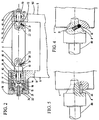
- FIG. 1 a notching machine provided with a shaping pulley assembly according to the present invention is shown therein in a fragmentary perspective view.
- a frame is designed in general as 1, and a vice for a tubular workpiece, that is shown without its support base on frame 1, is designed as 2.
- a pair of pulleys 3, 4 carry a grinding belt 5.
- the pulley 3 is a driving pulley for the grinding belt 5
- the pulley 4 is a shaping pulley co-operating with the grinding belt 5 to make recesses conventionally in a not shown tubular workpiece (not shown).
- the shaping pulley 4 is interchangeable with other pulleys of different diameter (not shown) so to permit that differently sized recesses can be performed.
- the shaping pulley 4 is a part of a shaping pulley assembly generally designed as 6.
- the shaping pulley 4 is in the form of a preferably solid, cylindrical roller, having bases 40, 41 in which opposite centre holes 42, 43 are formed (as shown in Fig. 3).
- the centre holes like the centre holes that are performed on heads of workpieces designed to be supported in the working operations on machine tools, can be of a standard type.
- the centre holes have a frustoconical section with a taper of 60 degrees internally ending with a cylindrical section being of a diameter equal to the diameter of the minor base of the frustoconical section.
- a centre and a counter-centre Inserted in the centre holes 42 and 43 are a centre and a counter-centre, which in all the figures, also if modified, are denoted generally in 7, and 8 respectively.
- the centre 7 and the counter-centre 8 are live centres and are supported in the shaping pulley assembly 6 by a pulley holder element 9 like a fork.
- the pulley holder element 9, which is supported by the frame 1 in a conventional way, has a C-shaped body with end brackets 90, 91.
- Each of the brackets 90, 91 is provided with a housing for rolling bearings that are selected to withstand both radial and axial loads to which the centres each to other opposite are subjected.
- the two housings on the brackets 90, 91 are mutually axial.
- a race 10 where the centre 7 is stationary mounted and on the bracket 91, on the counter-centre side, a seat 11 is inserted in which the counter-centre 8 is removably mounted.
- a hole 23 parallel to the axis of the pulley 4 is formed in the hole 42 of the pulley 4 for a pin 24 which is integral with the centre 7 in a corresponding way.
- the retaining means can be whether different, but mechanically equivalent, or they could not be necessary if the friction between the contacting surfaces of centre and counter-centre and the surfaces of the respective holes carried out in the idle shaping pulley is enough to let said centre and counter-centre to rotate together with the shaping pulley.
- the centre 7 and the counter-centre 8 include in addition to a common frustoconical portion, in their free end a cylindrical portion which is denoted in 25 for the support in respective centre holes.
- the cylindrical portion 25 could be useful in case a thrust on centre and counter-centre is accidentally reduced, if the frustoconical portion of the same should be no longer in contact with the respective centre holes.
- the frustoconical centre could be made with less convenience, instead on the supports of the shaping pulley, in the bases of the same shaping pulley in order to engage holes which are correspondingly carried out in the support of the pulley holder element.
- Both the centre 7 and the counter-centre 8 have a small shaft 70, 80 supported by a pair of radial (71, 81) and axial (72, 82) rolling bearings, which are spaced apart by a spacer.
- the roller bearings 71, 72 and 81, 82 are retained on the shaft and inside the respective seats of centre 10 and counter-centre 11 by means of an abutting shoulder 12, 13 and an axially fit Seeger type retaining ring 14 and a nut 15.
- the housing 11 thereof is made in the form of a cylindrical element which is mounted able to slide inside an hollow, cylindrical, externally threaded enlargement 16 which is carried out on the end bracket 91 of the pulley holder element 9 at right angles to the bracket 91.
- the cylindrical element 11 is prevented to rotate e.g. by a key 18 sliding in its slot 17 which is carried out in the bracket 91.
- An internally threaded cap 19 is screwed on the hollow cylindrical enlargement 16 in abutment with the free end of the sliding cylindrical element 17 by axially interposing spring charge means, such as Belleville washers 31 abutted between the interior of the cap and an internal counter-cap 32.
- the spring charge means serves to keep the pulley firmly engaged between centre and counter-centre, notwithstanding the stresses acting on the pulley.
- the internal counter-cap 32 is fixed on one side thereof to the cylindrical element 11 by pins 33, and it is connected on the other side thereof in a sliding way to the cap 19 e.g. by a bolt 34.
- the counter-centre 8 does not remain inside the pulley holder element 9 but it is drawn with it. It is evident that, if desired, this can be prevented without the provision of the counter-cap 32, by abutting the Belleville washers between the cap 19 and the cylindrical element 11 of the counter-centre 8.
- the counter-centre engaging the shaping pulley could be driven by different means, e.g. such as lever means, bayonet means or the like, which for example could increase the replacement speed of the shaping pulley.
Applications Claiming Priority (2)
| Application Number | Priority Date | Filing Date | Title |
|---|---|---|---|
| IT000499A ITRM20020499A1 (it) | 2002-10-04 | 2002-10-04 | Gruppo puleggia sagomatrice per scantonatrice a nastro. |
| ITRM20020499 | 2002-10-04 |
Publications (2)
| Publication Number | Publication Date |
|---|---|
| EP1405696A1 EP1405696A1 (en) | 2004-04-07 |
| EP1405696B1 true EP1405696B1 (en) | 2005-09-28 |
Family
ID=11456508
Family Applications (1)
| Application Number | Title | Priority Date | Filing Date |
|---|---|---|---|
| EP03425644A Expired - Lifetime EP1405696B1 (en) | 2002-10-04 | 2003-10-01 | Pulley assembly for the belt of a notching machine |
Country Status (18)
| Country | Link |
|---|---|
| US (2) | US6855038B2 (zh) |
| EP (1) | EP1405696B1 (zh) |
| JP (1) | JP3837406B2 (zh) |
| KR (1) | KR100611360B1 (zh) |
| CN (1) | CN1301182C (zh) |
| AT (1) | ATE305362T1 (zh) |
| AU (1) | AU2003252791B2 (zh) |
| CA (1) | CA2443177C (zh) |
| CZ (1) | CZ294494B6 (zh) |
| DE (1) | DE60301715T2 (zh) |
| DK (1) | DK1405696T3 (zh) |
| ES (1) | ES2248722T3 (zh) |
| IT (1) | ITRM20020499A1 (zh) |
| MX (1) | MXPA03008964A (zh) |
| PL (1) | PL362596A1 (zh) |
| RU (1) | RU2264905C2 (zh) |
| TR (1) | TR200301689A2 (zh) |
| TW (1) | TWI232789B (zh) |
Families Citing this family (6)
| Publication number | Priority date | Publication date | Assignee | Title |
|---|---|---|---|---|
| ITRM20020499A1 (it) * | 2002-10-04 | 2004-04-05 | Nuova Cmls R L Ora Cml Internationa L S P A | Gruppo puleggia sagomatrice per scantonatrice a nastro. |
| US7052381B1 (en) * | 2005-03-15 | 2006-05-30 | Mao Shan Machinery Industrial Co., Ltd. | Belt sander having tension adjustment mechanism |
| CN102218690B (zh) * | 2011-04-21 | 2012-12-19 | 西北工业大学 | 一种金相试样研磨抛光机 |
| KR101878895B1 (ko) * | 2016-11-07 | 2018-07-16 | 김효정 | 롤 교체장치 |
| US11072496B2 (en) * | 2017-10-05 | 2021-07-27 | Deere & Company | Sugarcane harvester elevator conveyor guide unit |
| CN108581744B (zh) * | 2018-05-31 | 2023-10-20 | 广东高力威机械科技有限公司 | 玻璃磨边机的开槽误差修正方法 |
Family Cites Families (21)
| Publication number | Priority date | Publication date | Assignee | Title |
|---|---|---|---|---|
| US294766A (en) | 1884-03-11 | Abrading-machine | ||
| US421228A (en) * | 1890-02-11 | Albert berthe | ||
| US344835A (en) * | 1886-07-06 | Polishing-machine | ||
| US334535A (en) * | 1886-01-19 | Magazine-gun | ||
| US1622758A (en) | 1923-08-06 | 1927-03-29 | Standard Conveyor Co | Roller for gravity conveyers |
| US1784848A (en) | 1927-11-09 | 1930-12-16 | Alvey Mfg Company | Bearing for conveyer rollers |
| US1999275A (en) | 1933-05-31 | 1935-04-30 | United Shoe Machinery Corp | Buffing machine |
| US4421228A (en) | 1981-08-17 | 1983-12-20 | Eastman Kodak Company | Periodically aligning an endless web |
| GB8923188D0 (en) | 1989-10-14 | 1989-11-29 | Ermanco Conveyors | Conveyors |
| JPH0722883B2 (ja) * | 1990-11-28 | 1995-03-15 | 三ツ星ベルト株式会社 | エンドレスベルトの偏倚防止装置及び該装置を用いたベルト加工装置 |
| DE4131523C2 (de) * | 1991-09-21 | 1995-08-17 | Baugeraete Union Gmbh & Co Mas | Bandschleifmaschine |
| BE1006202A3 (nl) | 1992-10-29 | 1994-06-07 | American Biltrite Inc | Passtuk voor de bevestiging en de vergrendeling van een vrij roterende vervangingsrol. |
| US5437570A (en) * | 1993-04-02 | 1995-08-01 | Almi Machinefabriek Bv | Apparatus for making cutouts in the ends of tubular workpieces |
| DE4310887B4 (de) * | 1993-04-02 | 2004-09-09 | Almi Machinefabriek Vriezenveen B.V. | Vorrichtung zum endseitigen Ausformen von rohrförmigen Werkstücken mit unterschiedlichen Durchmessern |
| US5421441A (en) | 1994-02-22 | 1995-06-06 | Mason; William R. | Stub axle assembly for conveyor roller |
| DE29504077U1 (de) * | 1995-03-10 | 1995-04-27 | Multi Tool A S | Bandschleifmaschine |
| DE19704086B4 (de) | 1997-02-04 | 2007-07-12 | Robert Bosch Gmbh | Handbandschleifer |
| AUPQ777500A0 (en) | 2000-05-26 | 2000-06-22 | Price, John Lewis | Grinding apparatus |
| DE60109217T2 (de) | 2001-09-07 | 2006-04-06 | New Tech S.R.L., Piedimonte San Germano | Horizontalmehrzweckpresse mit fixem werkstückhalter für rohrförmige werkstücke |
| US6733372B2 (en) | 2002-02-21 | 2004-05-11 | Kun Yi Lin | Grinding machine having adjustable mechanism |
| ITRM20020499A1 (it) | 2002-10-04 | 2004-04-05 | Nuova Cmls R L Ora Cml Internationa L S P A | Gruppo puleggia sagomatrice per scantonatrice a nastro. |
-
2002
- 2002-10-04 IT IT000499A patent/ITRM20020499A1/it unknown
-
2003
- 2003-09-23 TW TW092126174A patent/TWI232789B/zh not_active IP Right Cessation
- 2003-09-26 CZ CZ20032606A patent/CZ294494B6/cs not_active IP Right Cessation
- 2003-09-29 CA CA002443177A patent/CA2443177C/en not_active Expired - Fee Related
- 2003-10-01 MX MXPA03008964A patent/MXPA03008964A/es active IP Right Grant
- 2003-10-01 ES ES03425644T patent/ES2248722T3/es not_active Expired - Lifetime
- 2003-10-01 AT AT03425644T patent/ATE305362T1/de not_active IP Right Cessation
- 2003-10-01 EP EP03425644A patent/EP1405696B1/en not_active Expired - Lifetime
- 2003-10-01 DE DE60301715T patent/DE60301715T2/de not_active Expired - Lifetime
- 2003-10-01 DK DK03425644T patent/DK1405696T3/da active
- 2003-10-02 KR KR1020030068725A patent/KR100611360B1/ko not_active IP Right Cessation
- 2003-10-02 RU RU2003129289/02A patent/RU2264905C2/ru not_active IP Right Cessation
- 2003-10-02 AU AU2003252791A patent/AU2003252791B2/en not_active Ceased
- 2003-10-03 PL PL03362596A patent/PL362596A1/xx unknown
- 2003-10-03 JP JP2003346235A patent/JP3837406B2/ja not_active Expired - Fee Related
- 2003-10-06 US US10/678,218 patent/US6855038B2/en not_active Expired - Lifetime
- 2003-10-06 TR TR2003/01689A patent/TR200301689A2/xx unknown
- 2003-10-08 CN CNB2003101006083A patent/CN1301182C/zh not_active Expired - Fee Related
-
2004
- 2004-10-21 US US10/969,180 patent/US7044844B2/en not_active Expired - Fee Related
Also Published As
| Publication number | Publication date |
|---|---|
| KR100611360B1 (ko) | 2006-08-11 |
| ES2248722T3 (es) | 2006-03-16 |
| EP1405696A1 (en) | 2004-04-07 |
| ITRM20020499A0 (it) | 2002-10-04 |
| KR20040031623A (ko) | 2004-04-13 |
| MXPA03008964A (es) | 2004-09-10 |
| RU2003129289A (ru) | 2005-04-10 |
| DE60301715D1 (de) | 2006-02-09 |
| CA2443177C (en) | 2006-06-20 |
| US6855038B2 (en) | 2005-02-15 |
| DE60301715T2 (de) | 2006-07-06 |
| ITRM20020499A1 (it) | 2004-04-05 |
| TWI232789B (en) | 2005-05-21 |
| TR200301689A2 (tr) | 2004-07-21 |
| US20040097178A1 (en) | 2004-05-20 |
| TW200406281A (en) | 2004-05-01 |
| CN1301182C (zh) | 2007-02-21 |
| AU2003252791A1 (en) | 2004-04-22 |
| ATE305362T1 (de) | 2005-10-15 |
| US20050059326A1 (en) | 2005-03-17 |
| JP2004122357A (ja) | 2004-04-22 |
| AU2003252791B2 (en) | 2005-09-22 |
| CZ20032606A3 (cs) | 2004-10-13 |
| RU2264905C2 (ru) | 2005-11-27 |
| JP3837406B2 (ja) | 2006-10-25 |
| PL362596A1 (en) | 2004-04-05 |
| DK1405696T3 (da) | 2005-12-19 |
| US7044844B2 (en) | 2006-05-16 |
| CN1496785A (zh) | 2004-05-19 |
| CA2443177A1 (en) | 2004-04-04 |
| CZ294494B6 (cs) | 2005-01-12 |
Similar Documents
| Publication | Publication Date | Title |
|---|---|---|
| JP4727917B2 (ja) | インデックステーブル | |
| EP1405696B1 (en) | Pulley assembly for the belt of a notching machine | |
| CN110944793B (zh) | 带有径向夹持设备的工作芯轴 | |
| JP2012081543A (ja) | 工作機械および加工方法 | |
| US5337521A (en) | Valve grinder | |
| US2278264A (en) | Spindle bearing | |
| CN213317865U (zh) | 一种双工位的旋转工装 | |
| JP4681376B2 (ja) | ワークの溝の研磨方法 | |
| KR19990064128A (ko) | 공구착탈장치 | |
| CN217801030U (zh) | 一种辊轴承中滚柱加工用的夹持工装 | |
| US6536129B2 (en) | Centering device for a saw blade | |
| CN219767852U (zh) | 侧面研磨装置 | |
| US2435451A (en) | Headstock and centering rest assembly | |
| CN214025128U (zh) | 一种用于精密陶瓷部件加工的高效磨床设备组件 | |
| KR100825329B1 (ko) | 백업롤용 오토클램프 자동 장탈착장치 | |
| CN215968230U (zh) | 砂轮快换锁定机构 | |
| CN220260522U (zh) | 一种在普通卧式车床上使用的外圆抛光装置 | |
| KR100460316B1 (ko) | 파이프 전조장치 | |
| CN112222974A (zh) | 柴油机曲轴磨床驱动工装 | |
| CN115055970A (zh) | 一种轴承加工系统及加工方法 | |
| CN101489723B (zh) | 曲轴加工工具的测试设备 | |
| CN112605692A (zh) | 一种双向镗孔的托辊筒体车床 | |
| JPH09309012A (ja) | スピンドル装置 | |
| WO1998046385A1 (en) | Turret-mountable live center for lathes | |
| CN105014518A (zh) | 一种高精珩磨装置 |
Legal Events
| Date | Code | Title | Description |
|---|---|---|---|
| PUAI | Public reference made under article 153(3) epc to a published international application that has entered the european phase |
Free format text: ORIGINAL CODE: 0009012 |
|
| AK | Designated contracting states |
Kind code of ref document: A1 Designated state(s): AT BE BG CH CY CZ DE DK EE ES FI FR GB GR HU IE IT LI LU MC NL PT RO SE SI SK TR |
|
| AX | Request for extension of the european patent |
Extension state: AL LT LV MK |
|
| 17P | Request for examination filed |
Effective date: 20040506 |
|
| AKX | Designation fees paid |
Designated state(s): AT BE BG CH CY CZ DE DK EE ES FI FR GB GR HU IE IT LI LU MC NL PT RO SE SI SK TR |
|
| GRAP | Despatch of communication of intention to grant a patent |
Free format text: ORIGINAL CODE: EPIDOSNIGR1 |
|
| GRAS | Grant fee paid |
Free format text: ORIGINAL CODE: EPIDOSNIGR3 |
|
| GRAA | (expected) grant |
Free format text: ORIGINAL CODE: 0009210 |
|
| AK | Designated contracting states |
Kind code of ref document: B1 Designated state(s): AT BE BG CH CY CZ DE DK EE ES FI FR GB GR HU IE IT LI LU MC NL PT RO SE SI SK TR |
|
| PG25 | Lapsed in a contracting state [announced via postgrant information from national office to epo] |
Ref country code: IT Free format text: LAPSE BECAUSE OF FAILURE TO SUBMIT A TRANSLATION OF THE DESCRIPTION OR TO PAY THE FEE WITHIN THE PRESCRIBED TIME-LIMIT;WARNING: LAPSES OF ITALIAN PATENTS WITH EFFECTIVE DATE BEFORE 2007 MAY HAVE OCCURRED AT ANY TIME BEFORE 2007. THE CORRECT EFFECTIVE DATE MAY BE DIFFERENT FROM THE ONE RECORDED. Effective date: 20050928 Ref country code: BE Free format text: LAPSE BECAUSE OF FAILURE TO SUBMIT A TRANSLATION OF THE DESCRIPTION OR TO PAY THE FEE WITHIN THE PRESCRIBED TIME-LIMIT Effective date: 20050928 Ref country code: AT Free format text: LAPSE BECAUSE OF FAILURE TO SUBMIT A TRANSLATION OF THE DESCRIPTION OR TO PAY THE FEE WITHIN THE PRESCRIBED TIME-LIMIT Effective date: 20050928 Ref country code: TR Free format text: LAPSE BECAUSE OF FAILURE TO SUBMIT A TRANSLATION OF THE DESCRIPTION OR TO PAY THE FEE WITHIN THE PRESCRIBED TIME-LIMIT Effective date: 20050928 Ref country code: RO Free format text: LAPSE BECAUSE OF FAILURE TO SUBMIT A TRANSLATION OF THE DESCRIPTION OR TO PAY THE FEE WITHIN THE PRESCRIBED TIME-LIMIT Effective date: 20050928 Ref country code: FI Free format text: LAPSE BECAUSE OF FAILURE TO SUBMIT A TRANSLATION OF THE DESCRIPTION OR TO PAY THE FEE WITHIN THE PRESCRIBED TIME-LIMIT Effective date: 20050928 Ref country code: CZ Free format text: LAPSE BECAUSE OF FAILURE TO SUBMIT A TRANSLATION OF THE DESCRIPTION OR TO PAY THE FEE WITHIN THE PRESCRIBED TIME-LIMIT Effective date: 20050928 Ref country code: LI Free format text: LAPSE BECAUSE OF FAILURE TO SUBMIT A TRANSLATION OF THE DESCRIPTION OR TO PAY THE FEE WITHIN THE PRESCRIBED TIME-LIMIT Effective date: 20050928 Ref country code: EE Free format text: LAPSE BECAUSE OF FAILURE TO SUBMIT A TRANSLATION OF THE DESCRIPTION OR TO PAY THE FEE WITHIN THE PRESCRIBED TIME-LIMIT Effective date: 20050928 Ref country code: SI Free format text: LAPSE BECAUSE OF FAILURE TO SUBMIT A TRANSLATION OF THE DESCRIPTION OR TO PAY THE FEE WITHIN THE PRESCRIBED TIME-LIMIT Effective date: 20050928 Ref country code: SK Free format text: LAPSE BECAUSE OF FAILURE TO SUBMIT A TRANSLATION OF THE DESCRIPTION OR TO PAY THE FEE WITHIN THE PRESCRIBED TIME-LIMIT Effective date: 20050928 Ref country code: CH Free format text: LAPSE BECAUSE OF FAILURE TO SUBMIT A TRANSLATION OF THE DESCRIPTION OR TO PAY THE FEE WITHIN THE PRESCRIBED TIME-LIMIT Effective date: 20050928 |
|
| REG | Reference to a national code |
Ref country code: GB Ref legal event code: FG4D |
|
| REG | Reference to a national code |
Ref country code: CH Ref legal event code: EP |
|
| PG25 | Lapsed in a contracting state [announced via postgrant information from national office to epo] |
Ref country code: CY Free format text: LAPSE BECAUSE OF FAILURE TO SUBMIT A TRANSLATION OF THE DESCRIPTION OR TO PAY THE FEE WITHIN THE PRESCRIBED TIME-LIMIT Effective date: 20051001 |
|
| PG25 | Lapsed in a contracting state [announced via postgrant information from national office to epo] |
Ref country code: IE Free format text: LAPSE BECAUSE OF NON-PAYMENT OF DUE FEES Effective date: 20051003 |
|
| REG | Reference to a national code |
Ref country code: IE Ref legal event code: FG4D |
|
| PG25 | Lapsed in a contracting state [announced via postgrant information from national office to epo] |
Ref country code: MC Free format text: LAPSE BECAUSE OF NON-PAYMENT OF DUE FEES Effective date: 20051031 |
|
| PG25 | Lapsed in a contracting state [announced via postgrant information from national office to epo] |
Ref country code: LU Free format text: LAPSE BECAUSE OF NON-PAYMENT OF DUE FEES Effective date: 20051128 |
|
| REG | Reference to a national code |
Ref country code: DK Ref legal event code: T3 |
|
| PG25 | Lapsed in a contracting state [announced via postgrant information from national office to epo] |
Ref country code: SE Free format text: LAPSE BECAUSE OF FAILURE TO SUBMIT A TRANSLATION OF THE DESCRIPTION OR TO PAY THE FEE WITHIN THE PRESCRIBED TIME-LIMIT Effective date: 20051228 Ref country code: BG Free format text: LAPSE BECAUSE OF FAILURE TO SUBMIT A TRANSLATION OF THE DESCRIPTION OR TO PAY THE FEE WITHIN THE PRESCRIBED TIME-LIMIT Effective date: 20051228 Ref country code: GR Free format text: LAPSE BECAUSE OF FAILURE TO SUBMIT A TRANSLATION OF THE DESCRIPTION OR TO PAY THE FEE WITHIN THE PRESCRIBED TIME-LIMIT Effective date: 20051228 |
|
| REF | Corresponds to: |
Ref document number: 60301715 Country of ref document: DE Date of ref document: 20060209 Kind code of ref document: P |
|
| PG25 | Lapsed in a contracting state [announced via postgrant information from national office to epo] |
Ref country code: PT Free format text: LAPSE BECAUSE OF FAILURE TO SUBMIT A TRANSLATION OF THE DESCRIPTION OR TO PAY THE FEE WITHIN THE PRESCRIBED TIME-LIMIT Effective date: 20060228 |
|
| REG | Reference to a national code |
Ref country code: ES Ref legal event code: FG2A Ref document number: 2248722 Country of ref document: ES Kind code of ref document: T3 |
|
| PG25 | Lapsed in a contracting state [announced via postgrant information from national office to epo] |
Ref country code: HU Free format text: LAPSE BECAUSE OF FAILURE TO SUBMIT A TRANSLATION OF THE DESCRIPTION OR TO PAY THE FEE WITHIN THE PRESCRIBED TIME-LIMIT Effective date: 20060329 |
|
| REG | Reference to a national code |
Ref country code: CH Ref legal event code: PL |
|
| ET | Fr: translation filed | ||
| PLBE | No opposition filed within time limit |
Free format text: ORIGINAL CODE: 0009261 |
|
| STAA | Information on the status of an ep patent application or granted ep patent |
Free format text: STATUS: NO OPPOSITION FILED WITHIN TIME LIMIT |
|
| REG | Reference to a national code |
Ref country code: IE Ref legal event code: MM4A |
|
| 26N | No opposition filed |
Effective date: 20060629 |
|
| REG | Reference to a national code |
Ref country code: NL Ref legal event code: V1 Effective date: 20120501 |
|
| PGFP | Annual fee paid to national office [announced via postgrant information from national office to epo] |
Ref country code: DE Payment date: 20120426 Year of fee payment: 9 |
|
| PGFP | Annual fee paid to national office [announced via postgrant information from national office to epo] |
Ref country code: ES Payment date: 20120430 Year of fee payment: 9 |
|
| PG25 | Lapsed in a contracting state [announced via postgrant information from national office to epo] |
Ref country code: DE Free format text: LAPSE BECAUSE OF NON-PAYMENT OF DUE FEES Effective date: 20130501 |
|
| REG | Reference to a national code |
Ref country code: DE Ref legal event code: R119 Ref document number: 60301715 Country of ref document: DE Effective date: 20130501 |
|
| REG | Reference to a national code |
Ref country code: ES Ref legal event code: FD2A Effective date: 20140116 |
|
| PG25 | Lapsed in a contracting state [announced via postgrant information from national office to epo] |
Ref country code: ES Free format text: LAPSE BECAUSE OF NON-PAYMENT OF DUE FEES Effective date: 20121002 |
|
| REG | Reference to a national code |
Ref country code: FR Ref legal event code: PLFP Year of fee payment: 13 |
|
| REG | Reference to a national code |
Ref country code: FR Ref legal event code: PLFP Year of fee payment: 14 |
|
| REG | Reference to a national code |
Ref country code: FR Ref legal event code: PLFP Year of fee payment: 15 |
|
| REG | Reference to a national code |
Ref country code: FR Ref legal event code: PLFP Year of fee payment: 16 |
|
| PGFP | Annual fee paid to national office [announced via postgrant information from national office to epo] |
Ref country code: NL Payment date: 20181031 Year of fee payment: 16 |
|
| PGFP | Annual fee paid to national office [announced via postgrant information from national office to epo] |
Ref country code: GB Payment date: 20181030 Year of fee payment: 16 Ref country code: FR Payment date: 20181030 Year of fee payment: 16 |
|
| PGFP | Annual fee paid to national office [announced via postgrant information from national office to epo] |
Ref country code: DK Payment date: 20191030 Year of fee payment: 17 |
|
| REG | Reference to a national code |
Ref country code: NL Ref legal event code: MM Effective date: 20191101 |
|
| PG25 | Lapsed in a contracting state [announced via postgrant information from national office to epo] |
Ref country code: NL Free format text: LAPSE BECAUSE OF NON-PAYMENT OF DUE FEES Effective date: 20191101 |
|
| GBPC | Gb: european patent ceased through non-payment of renewal fee |
Effective date: 20191001 |
|
| PG25 | Lapsed in a contracting state [announced via postgrant information from national office to epo] |
Ref country code: FR Free format text: LAPSE BECAUSE OF NON-PAYMENT OF DUE FEES Effective date: 20191031 Ref country code: GB Free format text: LAPSE BECAUSE OF NON-PAYMENT OF DUE FEES Effective date: 20191001 |
|
| REG | Reference to a national code |
Ref country code: DK Ref legal event code: EBP Effective date: 20201031 |
|
| PG25 | Lapsed in a contracting state [announced via postgrant information from national office to epo] |
Ref country code: DK Free format text: LAPSE BECAUSE OF NON-PAYMENT OF DUE FEES Effective date: 20201031 |