EP1403645A1 - Détecteur et dispositif de tamisage pour canaux ioniques - Google Patents
Détecteur et dispositif de tamisage pour canaux ioniques Download PDFInfo
- Publication number
- EP1403645A1 EP1403645A1 EP20030027436 EP03027436A EP1403645A1 EP 1403645 A1 EP1403645 A1 EP 1403645A1 EP 20030027436 EP20030027436 EP 20030027436 EP 03027436 A EP03027436 A EP 03027436A EP 1403645 A1 EP1403645 A1 EP 1403645A1
- Authority
- EP
- European Patent Office
- Prior art keywords
- bundles
- emission
- ball lens
- optical
- wavelength
- Prior art date
- Legal status (The legal status is an assumption and is not a legal conclusion. Google has not performed a legal analysis and makes no representation as to the accuracy of the status listed.)
- Granted
Links
Images


Classifications
-
- G—PHYSICS
- G01—MEASURING; TESTING
- G01N—INVESTIGATING OR ANALYSING MATERIALS BY DETERMINING THEIR CHEMICAL OR PHYSICAL PROPERTIES
- G01N21/00—Investigating or analysing materials by the use of optical means, i.e. using sub-millimetre waves, infrared, visible or ultraviolet light
- G01N21/62—Systems in which the material investigated is excited whereby it emits light or causes a change in wavelength of the incident light
- G01N21/63—Systems in which the material investigated is excited whereby it emits light or causes a change in wavelength of the incident light optically excited
- G01N21/64—Fluorescence; Phosphorescence
- G01N21/645—Specially adapted constructive features of fluorimeters
- G01N21/6452—Individual samples arranged in a regular 2D-array, e.g. multiwell plates
-
- G—PHYSICS
- G01—MEASURING; TESTING
- G01N—INVESTIGATING OR ANALYSING MATERIALS BY DETERMINING THEIR CHEMICAL OR PHYSICAL PROPERTIES
- G01N21/00—Investigating or analysing materials by the use of optical means, i.e. using sub-millimetre waves, infrared, visible or ultraviolet light
- G01N21/62—Systems in which the material investigated is excited whereby it emits light or causes a change in wavelength of the incident light
- G01N21/63—Systems in which the material investigated is excited whereby it emits light or causes a change in wavelength of the incident light optically excited
- G01N21/64—Fluorescence; Phosphorescence
- G01N2021/6417—Spectrofluorimetric devices
- G01N2021/6419—Excitation at two or more wavelengths
-
- G—PHYSICS
- G01—MEASURING; TESTING
- G01N—INVESTIGATING OR ANALYSING MATERIALS BY DETERMINING THEIR CHEMICAL OR PHYSICAL PROPERTIES
- G01N21/00—Investigating or analysing materials by the use of optical means, i.e. using sub-millimetre waves, infrared, visible or ultraviolet light
- G01N21/62—Systems in which the material investigated is excited whereby it emits light or causes a change in wavelength of the incident light
- G01N21/63—Systems in which the material investigated is excited whereby it emits light or causes a change in wavelength of the incident light optically excited
- G01N21/64—Fluorescence; Phosphorescence
- G01N2021/6417—Spectrofluorimetric devices
- G01N2021/6421—Measuring at two or more wavelengths
-
- G—PHYSICS
- G01—MEASURING; TESTING
- G01N—INVESTIGATING OR ANALYSING MATERIALS BY DETERMINING THEIR CHEMICAL OR PHYSICAL PROPERTIES
- G01N21/00—Investigating or analysing materials by the use of optical means, i.e. using sub-millimetre waves, infrared, visible or ultraviolet light
- G01N21/62—Systems in which the material investigated is excited whereby it emits light or causes a change in wavelength of the incident light
- G01N21/63—Systems in which the material investigated is excited whereby it emits light or causes a change in wavelength of the incident light optically excited
- G01N21/64—Fluorescence; Phosphorescence
- G01N21/645—Specially adapted constructive features of fluorimeters
- G01N2021/6463—Optics
- G01N2021/6478—Special lenses
-
- G—PHYSICS
- G01—MEASURING; TESTING
- G01N—INVESTIGATING OR ANALYSING MATERIALS BY DETERMINING THEIR CHEMICAL OR PHYSICAL PROPERTIES
- G01N21/00—Investigating or analysing materials by the use of optical means, i.e. using sub-millimetre waves, infrared, visible or ultraviolet light
- G01N21/62—Systems in which the material investigated is excited whereby it emits light or causes a change in wavelength of the incident light
- G01N21/63—Systems in which the material investigated is excited whereby it emits light or causes a change in wavelength of the incident light optically excited
- G01N21/64—Fluorescence; Phosphorescence
- G01N21/645—Specially adapted constructive features of fluorimeters
- G01N2021/6484—Optical fibres
-
- G—PHYSICS
- G01—MEASURING; TESTING
- G01N—INVESTIGATING OR ANALYSING MATERIALS BY DETERMINING THEIR CHEMICAL OR PHYSICAL PROPERTIES
- G01N2201/00—Features of devices classified in G01N21/00
- G01N2201/06—Illumination; Optics
- G01N2201/063—Illuminating optical parts
- G01N2201/0638—Refractive parts
- G01N2201/0639—Sphere lens
Definitions
- the present invention generally relates to devices and methods for rapidly identifying chemicals with biological activity in liquid samples, particularly automated screening of low volume samples for new medicines, agrochemicals, or cosmetics.
- Drug discovery is a highly time dependent and critical process in which significant improvements in methodology can dramatically improve the pace at which a useful chemical becomes a validated lead, and ultimately forms the basis for the development of a drug.
- the eventual value of a useful drug is set by the timing of its arrival into the market place, and the length of time the drug enjoys as an exclusive treatment for a specific ailment.
- a major challenge for major pharmaceutical companies is to improve the speed and efficiency of this process while at the same time maintaining costs to an absolute minimum.
- One solution to this problem has been to develop high throughput screening systems that enable the rapid analysis of many thousands of chemical compounds per 24 hours.
- these systems use miniaturized assay systems that dramatically reduce reagent costs, and improve productivity.
- To efficiently handle large numbers of miniaturized. assays it is necessary to implement automatic robotically controlled analysis systems that can provide reliable reagent addition and manipulations.
- these systems and the invention herein are capable of interacting in a coordinated fashion with other systems sub-components, such as a central compound store to enable rapid and efficient processing of samples.
- Miniaturized high throughput screening systems require robust, reliable and reproducible methods of analysis that are sensitive enough to work with small sample sizes. While there are a large number of potential analysis methods that can successfully used in macroscopic analysis, many of these procedures are not easily miniaturizable, or lack sufficient sensitivity when miniaturized. This is typically nest because absolute signal intensity from a given sample decreases as a function of the size of the sample, whereas background optical or detector noise remains more or less constant for large or small samples.
- Preferred assays for miniaturized high throughput screening assays have a high signal to noise ratios at very low sample sizes.
- Fluorescence based measurements have high sensitivity and perform well with small samples, where factors such as inner filtering of excitation and emission light are reduced. Fluorescence therefore exhibit good signal to noise ratios even with small sample sizes.
- a particularly preferred method of using fluorescence based signal detection is to generate a fluorescent (emission) signal that simultaneously changes at two or more wavelengths.
- a ratio can be calculated based on the emission light intensify at the first wavelength divided by the emitted light intensity at a second wavelength. This use of this ratio to measure a fluorescent assay has several important advantages over other non-ratiometric types of analysis. Firstly, the ratio is largely independent on the actual concentration of the fluorescent dye that is emitting fluorescence. Secondly, the ratio is largely independent on the intensity of light with which the fluorescent compound is being excited.
- the ratio is largely independent of changes in the sensitivity of the detector, provided that is that these changes are the same for the detection efficiency at both wavelengths.
- Fluorescence assays that produce ratiometric emission readouts have gained in popularity as the advantages of the method have grown in acceptance. Changes in emission ratios at two more wavelengths can be created through a number of distinct mechanisms including electronic and conformational changes in a fluorescence compound. Typically, these changes can occur in response to a chemical reaction or binding of the fluorescent compound to a particular ion such as a metal ion like calcium or magnesium, or through a change in pH that influences the protonation state of the fluorescent compound.
- ratiometric changes in emission can be conveniently be obtained by exploiting the use of fluorescence resonance energy transfer (FRET) from one fluorescent species to another fluorescent species.
- FRET fluorescence resonance energy transfer
- This approach is predictable, sensitive and can give rise to large ratio changes at two well-defined and well spectrally resolved wavelengths.
- FRET can be generally applied to create ratio metric assays for a range of activities.
- patent WO 96/30540 (Tsien) describes a FRET based system to measure gene expression using a fluorogenic substrate of beta lactamase.
- Patent WO 96/41166 (Tsien) describes the use of a FRET based system to measure voltage across the plasma membrane of a cell.
- Patent WO 97/20261 (Tsien) describes the use of FRET between two fluorescent proteins to measure intracellular protein.
- Such assays can be used with the inventions described herein.
- the present invention is directed towards the development of improved optical systems and methods for simultaneously measuring emission ratios from a plurality of samples with high sensitivity, speed, reproducibility and accuracy.
- the present invention has several important advantages over prior methods and devices adapted to measure fluorescence emission sequentially from samples. Firstly, the simultaneous measurement of emission ratios enables rapid fluctuations in lamp intensity, bleaching of the fluorescent dye, or cycle to cycle errors in the alignment of multiwell plates to be corrected for, thereby enabling much smaller changes in ratio to be reliably observed. Secondly, no mechanical movements are necessary during ratio measurement, eliminating mechanical design challenges. Thirdly ratios can be acquired very rapidly, as required for dynamic measurements of membrane potential or calcium, and are not limited by the speed of filter changing. Fourthly the overall throughput and duty cycle are improved by eliminating dead times for filter changeover. Finally, residual ratio non-uniformities between addressable wells should be constant and easily correctable by using emission ratios previously measured on reference samples to normalize sample ratios in software.
- the invention includes a method of simultaneously measuring at least two optical properties of emitted light from at least one sample in a plurality of addressable wells of a multiwell plate, comprising the steps of,
- the invention includes an optical detection system, comprising a light source that launches at least one predetermined wavelength of light, sample holder, a ball lens at a predetermined interrogation distance from said sample holder, a trifurcated fiber adapted for dual optical interrogation and in optical communication with said ball lens, and a detector that detects light of at least one desired wavelength and in optical communication with said ball lens.
- the optical detection system includes a trifurcated fiber comprising a first plurality of emission bundles for receiving light of a first wavelength and second plurality of emission bundles for receiving light of a second wavelength and said first plurality of emission bundles and said light source launches at least one predetermined wavelength of excitation light at said sample holder.
- the optical detection system may further comprise at least one positioner to controllably change the spatial relationship between the ball lens and the fiber or sample or multiwell plate or a combination thereof.
- the light source launches light through said trifurcated fiber to the location at least one addressable well in a sample in said sample holder to monitor epifluorescence.
- the trifurcated fiber comprises an end that is generally at a focal plane of the ball lens.
- the invention also includes an optical fiber assembly, comprising a trifurcated fiber comprising a first plurality of emission bundles for receiving light of a first wavelength and second plurality of emission bundles for receiving light of a second wavelength and said first plurality of emission bundles and said second plurality of emission bundles are non- randomly distributed in plurality of excitation bundles.
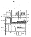
- FIG. 1 shows one device of the invention.
- a device integrates a liquid handler 115 , a multiwell positioning stage 112 and a detection device comprising the ball lens trifurcated fiber optic bundle ball lens assembly of the invention.
- the vertical position of the optical assembly can be adjusted by a stepper motor driven cam system (further described in FIG. 6 ).
- Thc assemblies are lowered when the plate is moved in or out of the system to allow me skirt of the microplate to pass over the trifurcated fiber optic bundle ball lens assembly.
- the assemblies (further described in FIG. 5 ) are raised once the plate is in the system to maximize fluorescence detection efficiency. Plates containing cells and compounds are loaded into the device either manually or by a computer-controlled arm.
- a multiwell plate positioning stage 112 such as a 500000 series, Parker Hannifin Corp, Harrison City, PA, may also be used to control movement of the multiwell plate.
- the liquid handler 115 may be a modified Hamilton Micro Lab 2000 MPH, Hamilton Co, Reno, NV), with at least 1 dispensing tip 114 and associated pump 107 , waste container 108 and diluent container 109 .
- the detector module 111 comprises 16 photomultipliers, (Hamamatsu HC124-01) that are used to detect fluorescence emission at a rate of 1Hz or 10Hz.
- Two photomultiplier tubes are used to detect fluorescence from each well in a column of 8 wells allowing for continuous emission ration detection.
- the blue-sensitive bi-alkali photomultiplier tube is typically used to detect the shorter wavelength emission (300 to 650 nm) while the multi-alkali photomultiplier tube is used to detect longer wavelength emission (300 to 850 nm).
- a computer 105 , and graphical user interface 101 coordinates the functions of the liquid handler 115 , multiwell plate positioning stage 112 , detector module 111 and data collection 106 . Data collection can be viewed through a monitor in real-time via a computer monitor 103.
- a central power switch can be used to switch the device on and off 104 .
- monolayers of cells can be detected on the bottom of microplate wells 206 by the common end of a trifurcated optical fiber bundle 203.
- One leg of the each trifurcated fiber bundle is used as an excitation source 201; each of the eight excitation legs is fused into a single bundle 204 to provide uniform light intensity to each of the eight trifurcated bundles.
- the other two legs of the trifurcated fiber are used for to detect fluorescence emission 214 and 213.
- the common end of the trifurcated bundle is used to both excite and collect fluorescence emission.
- Eight trifurcated fibers are used to detect two emission channels from each well in a column of eight wells.
- a ball lens 205 (RB-707004, Bird Precision, Waltham, MA) may be included at the top of the common end of the trifurcated fiber bundle to increase the efficiency of fluorescence detection.
- a 300 watt xenon arc lamp 201 e.g. CXP300, ILC Technology, Sunnyvale, CA
- a parabolic reflector can be used as the fluorescence excitation source.
- the excitation light is filtered by two 2" diameter interference filters (e.g. 400RDF15 or 480RDF20, Omega Optical, Brattleboro, VT) and then focused by a lens 202 on to the excitation leg of the trifurcated bundle.
- Both a IR heat absorbing water filter 208 and shutter system 207 are also included in the optical path to protect the interference filters from heat damage.
- A1" diameter "head-on" photomultiplier (e.g.HC124 series, Hamamatsu Corp, Bridgewater, NJ) tubes are used to detect the fluorescence emission. Fluorescence emission from one leg of the fiber bundle is detected by a blue-sensitive bi-alkalai photomultiplier tube 209; emission from the other leg of the fiber bundle is detected by a red-sensitive multi-alkalai photomultiplier tube 210. Data is collected by the A/D portion of a multifunction board (e.g. PCI-MIO-E-1, National Instruments, Dallas, TX) in a Pentium TM based personal computer 212 . The computer controls data acquisition, plate and fiber movement, and shutter opening and closing 215.
- a multifunction board e.g. PCI-MIO-E-1, National Instruments, Dallas, TX
- the detection system might comprise the excitation source and associated optics (dichroic filters, interference filters, focussing lenses, collimators, etc), the fiber optic assembly (excitation and emission pathways and patterns), the substrate containing sample to be analyzed, and the emission filters and associated optics that direct the emission radiation to the detection element.
- a key challenge in epifluorescent detection is to maximize the excitation light energy and the area (the field of view created by the excitation light) this energy is delivered to the sample, without comprising the efficient collection of the fluorescent emission or generating a high background from the reflection of excitation radiation.
- the wavelength to be utilized for excitation may preclude the use of certain materials (which might have other desirable features like high numerical aperture (NA)) due to the incompatibility of the material (high autofluorescence) with the excitation wavelength that is required.
- NA numerical aperture
- the ultimate sensitivity of fluorescent detectors is thus often limited by the amount, and drift in background noise sources that are mainly generated at the various optical interfaces, where reflection and refraction takes place.
- a detection system of the invention includes a ball lens in optical communication with a tetra, tri- or bi-furcated fiber optic bundle that is in optical communication with a photon detector.
- a liquid handling system is included to provide predetermined dispensing at a designated time and volume.
- dispensation and optical interrogation are coordinated by computer control.
- a first positioner controls the interrogation distances between a ball lens and sample or sample holder.
- a second positioner may be included (either with or without the first positioner to control the transmission distance between a ball lens and the fiber bundle.
- Ball lenses provide a compact, wide field of view lens, that when coupled with a suitable fiber optic bundle arrangement significantly reduces background noisc.
- the ball lens trifurcated fiber optic assemblies of the invention are effective in directing light from the light source into the sample in the addressable well, and of efficiently focusing emitted light from the sample to the emission legs of the trifurcated fiber optic bundle.
- the light focusing ability of ball lens of various sizes and compositions are shown in FIG 4 .
- Such ball lens comprising of glass, sapphire or fused silica can collect emission light from up to about 65° from the optical axis, and maintain a high numerical aperture (NA) even with an air gap of 50-100 ⁇ m between the apex of the ball lens and bottom of the multiwell plate.
- NA numerical aperture
- vignetting the variation in lens image intensity between the center to the edge of the image, is minimal across the fiber optic face plate.
- a trifurcated fiber optic bundle is used in conjunction with a ball lens.
- a plurality of excitation fibers are coaxially arranged within the trifurcated fiber optic bundle and direct the light substantially through the axis of symmetry of the ball lens. Under these conditions, the excitation light is confined to ⁇ 11° of the optical axis, therefore the side walls of the addressable wells of the multiwell plate are not illuminated, reducing background scattering and fluorescence.
- Signal to noise ratios can be determined by comparing the magnitude of a defined amount of fluorescent material measured in the optical system, compared to the noise obtained by measuring an empty well under exactly the same conditions. S/N ratios can be calculated at a range of concentrations of the calibration material (for example, fluorescein) to determine overall detector sensitivity and linearity. Additionally, variability of measurements can be expressed in terms of standard deviation (S.D.) and Coefficient of Variance (C.V.) to establish reproducibility and alignment sensitivity of each of the systems.
- S.D. standard deviation
- C.V. Coefficient of Variance
- the spacing of the fiber optic bundle to the ball lens and the ball lens to the surface of the object to be optically interrogated can be quickly accomplished by generating a graph of S/N ratio versus interrogation or transmission distance for each of the optical arrangements desired.
- similar S/N ratio graphs can be created for each of the combinations in response to different illumination intensities and wavelengths of excitation light (in conjunction with appropriate fluorescent samples). This analysis would create a matrix of performance characteristics as represented by S/N ratios that are used to select the optimal fiber optic assemblies, ball lens size, composition, antireflective coating, and spatial alignments of the components for specific applications.
- fiber optic bundles may be created with varying packing patterns of excitation and emission bundle numbers and arrangements, and with different numbers of fibers in the excitation legs and emission legs.
- the packing of the fibers of both the excitation and emission legs in the bundle is randomly packed.
- the fibers are arranged in specific and defined patterns, that confers a preferred optical characteristic to the system.
- the excitation fibers could be bundled to together centrally in the fiber optic bundle and the emission filters arranged around the outside to create a coaxial fiber optic bundle. Both bifurcated and trifurcated fiber bundles can be produced in this preferred configuration.
- the emission bundles could be arranged in small groups to create an array, or radially around the axis of the bundle, or any other symmetrical or non-symmetrical pattern.
- Fiber optic assembles may also vary in total number of fibers of both the excitation and emission legs and overall size.
- the number of excitation fibers and the number of emission fibers and the relative ratios of excitation fibers to emission fibers may be widely varied depending upon the other components in the system, as well as the type of light source, sensitivity of the detector and size of the addressable well in which the sample is located. The optimization of these factors is discussed herein.
- a fiber optic bundle may contain a total of 341 fibers of which 55 will be excitation fibers arranged randomly within the fiber.
- the fiber may have 341 fibers of which 85 fibers are excitation fibers arranged in preferentially within the center of the bundle, but also distributed randomly through the remainder of the emission bundles.
- the fiber may contain 112 fibers of which 7 fibers are excitation fibers arranged in the center of the bundle, and the remaining emission fibers arc located around the excitation fibers.
- the fiber may contain 1417 fibers of which 163 fibers are excitation fibers arranged in the center of the bundle, and the remaining emission fibers are located around the excitation fibers.
- the excitation fibers are centrally located within the bundle and extend beyond the point where the emission fibers terminate.
- the emission filters terminate into a liquid light guide that is in contact with the ball lens.
- the percent of excitation to emission fibers in the trifurcated fiber optic bundle ranges from about 5 to 10 percent excitation fibers, or about 10-20 percent excitation fibers or about 20-40 percent excitation fibers.
- Ball lens compositions of materials of different refractive index and of different sizes can be easily evaluated with each fiber optic arrangement to establish a preferred optical arrangement.
- Ball lens of about 1 mm, 2 mm, 3 mm, 4 mm, 5 mm, 6 mm, 8 mm, 10 mm and 20 mm diameter may be evaluated depending on the size of the instrument and spatial requirements of the imaging system desired.
- Suitable compositions of the ball lens include fused silica, sapphire, optical glass (such as BK7, SF11 or LaSF9), borosilicate glass or zinc selenide (for infrared applications).
- Preterred compositions of the ball lens for use within the wavelength range 300-750 nm include fused silica and sapphire.
- a suitable anti-reflective coating such as single or multi-layer MgF 2 , V-coatings, HEBBAR TM (High Efficiency Broadband AntiReflection) and Extended range AntiRcflective coatings for a ball lens.
- size and AntiReflective coating (AR) of the lens different coatings each size of ball lens above made of each of the materials above would be prepared with each of the AR coatings above, and in the absence of an AR coating and evaluated as described herein.
- the detector can include at least one photon sensitive surface or material for measuring photon emission, such as a charged coupled device (CCD), photodiode, or a photomultiplier tube (PMT).
- the detector can intensify the signal, and gate if desired, using a photon intensifier.
- the detector can utilize a high quantum efficiency CCD without an intensifier for long detection integration.
- the detector can utilize a plurality of PMT's or multi-site PMT's for simultaneous photon detection and quantitation at two wavelengths from a plurality of addressable wells.
- the detector preferably functions in the epi-fluorescence mode where the preferred illumination is from the bottom of the multiwell plate and the preferred collection is also from the bottom of the multiwell plate.
- the detector usually is capable of three to four orders of magnitude of dynamic range in signal response from a single reading.
- the detector in one embodiment, utilizes a CCD chip for imaging and detecting photons emitted from the assay wells.
- the detector comprises a light source assembly (e.g., Xenon lamp) that can be switched (either manually or through computer control) between continuous and pulsed (1kHz) output depending upon power supply.
- a light source assembly e.g., Xenon lamp
- Suitable light sources for example lasers, light emitting diodes (LEDs) or mercury arc lamps arc also suitable as are other light sources that arc described herein and other suitable sources can be developed in the future.
- the liquid handler can comprise a plurality of nanoliter pipetting tips that can individually dispense a predetermined volume.
- pipetting tips are arranged in two-dimension array to handle plates of different well densities (e.g., 96, 384, 864 and 3,456).
- the dispensed volume will be less than approximately 2,000 microliters of liquid that has been aspirated from a predetermined selection of addressable wells and dispensed into a predetermined selection of addressable wells.
- nanoliter pipetting tips can dispense less than approximately 500 nanoliters, more preferably less than approximately 100 nanoliters, and most preferably less than approximately 25 nanoliters. Dispensing below 25 nanoliters can be accomplished by pipetting tips described herein.
- Preferred, minimal volumes dispensed are 5 nanoliters, 500 picoliters, 100 picoliters, 10 picoliters. It is understood that pipetting tips capable of dispensing such minimal volumes are also capable of dispensing greater volumes.
- the maximal volume dispensed will be largely dependent on the dispense time, reservoir size, tip diameter and pipetting tip type. Maximum volumes dispensed are about 10.0 microliters, 1.0 microliters, and 200 nanoliters. Preferably, such liquid handlers will be capable of both dispensing and aspirating.
- a nanoliter pipetting tip (or smaller volume dispenser) comprises a fluid channel to aspirate liquid from a predetermined selection of addressable wells (e.g., chemical wells containing drug candidates).
- addressable wells e.g., chemical wells containing drug candidates.
- Liquid handlers are further described herein, and for some volumes, typically in the microliter range, suitable liquid pipetting tips known in the art or developed in the future can be used.
- liquid handlers capable of handling about 1 to 20 microliter volumes when it is desired to make daughter plates from master plates.
- a liquid handler has a dispensing nozzle that is adapted for dispensing small volumes and can secure a tip having a fluid reservoir.
- nanoliter pipetting tips comprise solenoid valves fluidly connected to a reservoir for liquid from an addressable chemical well.
- the fluid reservoir can be a region of a dispenser that can hold fluid aspirated by the nanoliter pipetting tip.
- a tip reservoir will hold at least about 100 times the minimal dispensation volume to about 10,000 times the dispensation volume and more preferably about 250,000 times the dispensation volume.
- the solenoid valves control a positive hydraulic pressure in the reservoir and allow the release of liquid when actuated.
- a positive pressure for dispensation can be generated by a hydraulic or pneumatic means, e.g., a piston driven by a motor or gas bottle.
- a negative pressure for aspiration can be created by a vacuum means (e.g., withdrawal of a piston by a motor).
- two solenoid valves or more can be used where the valves are in series and fluid communication.
- nanoliter pipetting tips comprise an electrically sensitive volume displacement unit in fluid communication to a fluid reservoir.
- the fluid reservoir holds liquid aspirated from an addressable chemical well.
- Electrically sensitive volume displacement units are comprised of materials that respond to an electrical current by changing volume.
- such materials can be piezo materials suitably configured to respond to an electric current.
- the electrically sensitive volume displacement unit is in vibrational communication with a dispensing nozzle so that vibration ejects a predetermined volume from the nozzle.
- piezo materials are used in dispensers for volumes less than about 10 to 1 nanoliter, and are capable of dispensing minimal volumes of 500 to 1 picoliter.
- Piezo pipetting tips can be obtained from Packard Instrument Company, Connecticut, USA (e.g., an accessory for the MultiProbe 104). Such small dispensation volumes permit greater dilution, conserve and reduce liquid handling times.
- the liquid handler can accommodate bulk dispensation (e.g., for washing).
- a bulk dispensation means By connecting a bulk dispensation means to the liquid handler, a large volume of a particular solution to be dispensed many times.
- Such bulk dispensation means for example a modified Hamilton Micro Lab 2200, ( MPH, Hamilton Co, Reno, NV ) are known in the art and can be developed in the future. Positioners, transitional stages
- Interrogation, aspiration or dispensation into multiwell plates of different densities can be accomplished by automated positioning (e.g. orthogonal) of a multiwell plate.
- the multiwell plates are securely disposed on an orthogonal positioner that moves the wells of a multiwell plate with a first density in an X,Y position with respect to the X,Y position of the liquid handier.
- the liquid handler will have an array of aspiration and/or dispensation heads, or both. Many aspiration/dispensation heads can operate simultaneously.
- the orthogonal positioner will align each addressable well with the appropriate dispensing head.
- a predetermined location (e.g., center) of a pre-selected addressable well will be aligned with the center of a dispensing head's fluid trajectory.
- Other alignments can be used, such as those described in the examples.
- An orthogonal positioner can typically match an array of dispensing heads with an array of addressable wells in X,Y using a mechanical means to move the addressable wells into position or the liquid handler (e.g., dispensing heads) into position.
- arrays of addressable wells on a plate are moved rather than the liquid handler.
- the mechanical means can be a first computer-controlled servo motor that drives a base disposed on a X track and a second computer-controlled servo motor that drives a Y track disposed on the X track.
- the base can securely dispose a multiwell plate and either a feedback mechanism or an accurate Cartesian mapping system, or both that can be used to properly align addressable wells with heads. Other such devices, as described herein, known in the art or developed in the future to accomplish such tasks can be used.
- such devices will have an X,Y location accuracy and precision of at least ⁇ 0.3 mm in X and ⁇ 0.3 mm in Y, preferably of at least ⁇ 0.09 mm in X and ⁇ 0.09 mm in Y, and more preferably of at least ⁇ 0.01 mm in X and ⁇ 0.01 mm in Y.
- detectors to identify the addressable wells or multiwell plates being orthogonally positioned.
- Such positioners for predetermined X, Y coordinates can be made using lead screws having an accurate and fine pitch with stepper motors (e.g., Compumotor Stages from Parker, Rohnert Park, CA, USA).
- Positioners e.g. X, Y or Z
- the liquid handler can be disposed on a Z-positioner, having an X,Y positioner for the liquid handler in order to enable precise X,Y and Z positioning of the liquid handler (e.g., Linear Drives of United Kingdom).
- a Z-positioner having an X,Y positioner for the liquid handler in order to enable precise X,Y and Z positioning of the liquid handler (e.g., Linear Drives of United Kingdom).
- a reference point or points can be included in the set up to ensure that a desired addressable well is properly matched with a desired addressable head.
- the multiwell plate, the orthogonal positioner or the liquid handler can include a reference point(s) to guide the X,Y alignment of a plate, and its addressable wells, with respect to the liquid handler.
- the liquid handler has a detector that corresponds in X,Y to each corner of a plate.
- the plate has orifices (or marks) that correspond in X,Y to the liquid handler's position detectors.
- the plate's orifices allow light to pass or reflect from a computer-controlled identification light source located on the orthogonal positioner in the corresponding X,Y position.
- Optical locators known in the art can also be used in some embodiments (PCT patent application WO91/17445 (Kureshy)). Detection of light by the liquid handler emitted by the orthogonal positioner verifies the alignment of the plates. Once plate alignment is verified, aspiration or dispensation can be triggered to begin. Stepper motors can be controlled for some applications as described in U.S. Patent 5,206,568 (Bjornson).
- the liquid handler will also typically be disposed on a Z-dimensional positioner to permit adj ustments in liquid transfer height. This feature allows for a large range of plate heights and aspirate and dispense tips, if desired, to be used in the sample distribution module. It also permits the dispense distance between a addressable well surface, or liquid surface in an addressable well, and a liquid handler to be adjusted to minimize the affects of static electricity, gravity, air currents and to improve the X,Y precision of dispensation in applications where dispensation of a liquid to a particular location in a addressable well is desired. Alternatively, multiwell plates can be positioned on a Z-dimensional positioner to permit adjustments in liquid transfer height. Static neutralizing devices can also be used to minimize static electricity.
- the liquid transfer height will be less than about 2 cm.
- small volumes will be dispensed at a liquid transfer height of less than about 10 mm, and more preferably less than about 2 mm.
- the ball lens assembly will also typically be disposed on a Z-dimensional positioner to permit adjustments in interrogation distance and transmission distance.
- a Z-dimensional positioner to permit adjustments in interrogation distance and transmission distance.
- the assemblies are lowered when the plate is moved in or out of the system to allow the skirt of the microplate to pass over the trifurcated fiber optic bundle ball lens assembly.
- the assemblies may be raised once the plate is in the system to control the interrogation distance to improve fluorescence detection efficiency.
- multiwell plates can be positioned on a Z-dimensional positioner to permit adjustments in interrogation distance.
- the transmission distance between the ball lens and fiber optic bundle would be fixed at a preferred distance, for optimal fluorescence detection.
- adjustments in transmission distance could be under programmable control to optimize the sensitivity and reproducibility of fluorescence measurements.
- a data processing and integration module can integrate and programmably control a liquid handler module, and a detector module to facilitate rapid processing of the multiwell wells.
- the data processing and integration module can also control the distance of the ball lens assembly to the sample (the interrogation distance), and the distance of the ball lens to the trifurcated fiber optic bundle (the transmission distance).
- the data processing and integration module comprises elements to store, manage and retrieve data, including a data storage device and a processor.
- the data storage device can hold a relational database, an array of physical disk drives (e.g., random access disk drives), and a connection to other system components via a network.
- a data storage device can, for instance, store a relational database for environmental, diagnostic, and drug discovery applications.
- a relational database for environmental, diagnostic, and drug discovery applications.
- one particularly useful relational database can be provided by Oracle, and the network can he a TCP/IP (transfer communication protocol) ethernet LAN (local area network).
- the device of the invention can be integrated with at least one other workstation, usually a sample transporter.
- the integration can be accomplished with a computer and associated control programs to instruct the translational stage and sample processor to operate coordinately.
- the device may be used without directly integrating to another workstation by tracking addressable wells in groups and either mechanically or manually transporting multiwell plates to another workstation where the multiwell plates are identified.
- the device of the invention may be directly integrated and operably linked to a storage and retrieval module arid sample transporter, and indirectly linked to an integration and control module. While this approach is feasible, especially for lower throughputs, it is not desirable for higher throughputs as it lacks direct integration that can lead to faster throughput times. Manual operations also arc more frequently subject to error especially when processing large numbers of samples.
- the device of the invention can be integrated with other workstations and operate in a mode with minimal or substantially no manual intervention related to transferring multiwell plates to other work stations.
- the detector module and its system are often capable of many different operating modes that facilitate drug discovery assay requirements. These operating modes can include: single excitation wavelength with single emission wavelength detection, single excitation wavelength, dual emission wavelength detection, sequential or dual excitation wavelength with dual emission wavelength detection and ratio measurement. determination. sequential dual excitation wavelengtl with four emission wavelength detection and ratio measurement determination, homogeneous time resolved fluorescence with single excitation wavelength and single emission wavelength detection, homogeneous time resolved fluorescence with single excitation wavelength and dual emission wavelength detection and ratio determination measurement, homogeneous time resolved fluorescence with sequential dual excitation wavelength and dual emission wavelength detection and ratio determination measurement, absorbancc (e.g. dual), transmittance (e,g.
- fluorescent monitoring systems can be used to practice the invention with fluorescent probes, such as fluorescent dyes or substrates.
- systems dedicated to high throughput screening e.g., 96-well or greater microtiter plates.
- Methods of performing assays on fluorescent materials are well known in the art and are described in, e.g., Lakowicz, J.R., Principles of Fluorescence Spectroscopy, New York: Plenum Press (1983); Herman, B., Resonance Energy Transfer Microscopy, in: Fluorescence Microscopy of Living Cells in Culture , Part B, Methods in Cell Biology, vol. 30, ed. Taylor, D.L.
- FRET fluorescence resonance energy transfer
- the degree of FRET can be determined by any spectral or fluorescence lifetime characteristic of the excited construct, for example, by determining the intensity of the fluorescent signal from the donor, the intensity of fluorescent signal from the acceptor, the ratio of the fluorescence amplitudes near the acceptor's emission maxima to the fluorescence amplitudes near the donor's emission maximum, or the excited state lifetime of the donor.
- cleavage of the linkcr increases the intensity of fluorescence from the donor, decreases the intensity of fluorescence from the acceptor, decreases the ratio of fluorescence amplitudes from the acceptor to that from the donor, and increases the excited state lifetime of the donor.
- changes in signal are determined as the ratio of fluorescence at two different emission wavelengths, a process referred to as "ratioing.” Differences in the absolute amount of probe (or substrate) cells, excitation intensity, and turbidity or other background absorbencies between addressable wells can affect the fluorescence signal. Therefore, the ratio of the two emission intensities is a more robust and preferred measure of activity than emission intensity alone.
- Arrangements of ball lenses and trifurcated fibers can be tailored to their intended applicatiun. To determine the appropriate arrangement of fiber optic bundles and ball lens a series of experiments can be conducted to determine the highest signal to noise ratio, preferred sensitivity, lowest background, preferred field of optical interrogation or excitation or a combination thereof.
- a trifurcated fiber optic assembly adapted for miniaturized sample analysis of a 1 mm well diameter with a variable interrogation layer of approximately 0.1 mm to 2.0 mm could comprise the following arrangement.
- a ball lens made of fused silica material coated with an antireflective coating such as HEBBAR, with a diameter of about 3mm.
- a trifurcated fiber optic assembly, optically coupled to the ball lens comprising 91 fibers, of which 7 fibers in the center are for excitation, and the remaining fibers are for emission collection.
- the fiber assembly being about 3mm in diameter and packed into a hexagonal ferrule to maximize packing efficiency and ease of assembly.
- the emission fibers (42 for each optical property to be measured) are selected so as to maximize collection efficiency, signal intensities and signal to noise or signal to background) properties of the assembly.
- Table 1 illustrates the effect that the spatial position of the ball lens to the fiber assembly has on signal-to-background ratios.
- the interrogation distance of the ball lens to the test fluorescent sample was kept constant as the transmission distance of the ball lens to the fiber optic assembly was varied
- Different signal (10 nM fluorescien-10 nM F) to background (BB ) ratio's were obtained from which an optimal transmission distance could be selected, which under these conditions was 0.482 mm
- Table 1 Emission filter: 535RDF30 (no long pass) Sample volume: 2 microliters, hand loaded.
- Table 2 Distance from fiber to lens 0.584 mm lens-too-plate (mm) Empty (mV) Buffer (BB) (mV) 10 nM F (mV) (10 nM F - BB)/BB 0 7.9 7.15 122 16 0.152. 7.8 7.2 126 17 0.203 8.4 8.15 119.5 14 0.305 10 8.9 118 12
- a series of fiber optic bundle assemblies were compared under identical conditions. In this case, a 3mm HEBBAR coated sapphire ball lens was utilized with four different fiber optic assemblies (as shown in FIG. 3). These assemblies contained varying numbers and arrangements of both excitation and emission fibers.
- Fiber optic bundle assembly performance was assessed by measuring the minimum detectable level (MDL) of a particular dye as described herein.
- MDL minimum detectable level
- Table 3 Description of Assembly MDL in nM of Fluorescein Number of Ex Fibers Number of Em Fibers Fiber Assembly Diameter Assembly #1 0.50 7.00 84.00 2.6mm Assembly #2 0.86 1.00 6.00 1.2mm Assembly #3 0.50 3.00 16.00 1.5mm Assembly #4 0.50 7.00 30.00 1.6mm
- assemblies #3 and #4 perform (as shown in FIG. 3) as well as assembly #1. Even though assembly one is significantly larger than the other assemblies, and contains more fiber optic fibers ( FIG. 3 ).
- the ball lens can thus aid in reducing the complexity or quantity of fibers required in a fiber optic assembly for optimal detection sensitivity particularly when the need to reduce the size of the fiber optic assembly is important in a miniaturized system.
- Table 4 the fiber assembly is kept constant but the size of the ball lens is varied.
- a 3mm diameter coaxial fiber optic - (3mmCoAX) assembly containing 112 fibers arranged with 7 XXF200/210/235T fused silica excitation fibers in the center of the assembly surrounded by 105 XXF200/210/235T fused silica emission fibers is used with three different size sapphire ball lenses, of external diameters of 3mm, 5mm and 10mm.
- Table 4 illustrates, sensitivity as measured by MDL determinations, sensitivity improves as ball lens size increases.
- the minimum detectable level (MDL) was calculated by generating a fluorescein calibration curve that enabled the concentration of fluorescein that was equivalent to 4 times the standard deviation of the buffer blank to be calculated.
- Buffer blank (BB) measurements are determined from the variance of readings from many buffer blanks and would be affected by well to well variability, positioning artifacts and other errors.
- MDL2 is determined from the variance of repeated measurements of the same buffer blank and presumably would be affected only by the noise of the detector.
- the optical detectors utilized to evaluate fluorescent intensity in the experiments were either a Hamamatsu PMT and associated electronics as described in the Fluorocaunt instrument or a Hamamatsu HC133-01/100Mhz PMT sensor module with embedded micro controller and RS-232-C interface. This sensor operates in the 360-650 nm range. A Labview TM software interface was written to control the PMT and acquire data. When needed, excitation radiant power was measured using a Newport Corporation 1835-C power meter equipped with a 818-UV NIST traceable silicon photodiode detector. The filters used in these experiments were obtained from Chroma Technology Corporation or Omega Optical Inc., with the exception of neutral density filters that were obtained from Oriel Corp.
- the standard plate is a 96 well black top clear bottom polystyrene plate filled with fluorescent standards.
- the glass bottom plates were specially modified black polystyrene 96 well plates with 175 micron glass bottoms. 384 well black polystyrene glass bottom plates were utilized for the 384 well readings. These specially modified plates were obtained from polyfiltronics/Whitman.
- the fiber optic assemblies were composed of fused silica coated with a black polyimide coating obtained from Fiberguide.
- the individual fibers are 200/220/240 in microns in diameter for the core/cladding/coating respectively unless otherwise specified in particular experiments.
- This example demonstrates the ability of the optical assemblies to achieve uniform illumination of the addressable wells while at the same time avoiding illumination of the sides of the well and the illumination of adjacent wells. This leads to reduced background fluorescent signals caused hy reflections from the plate and wells and reduces punch through of excitation light through emission filters into detection system, yet enables high sensitivity detection at two wavelengths.
- the minimum detectable fluorescein level achieved using a detector incorporating the optical system of the invention was better than 50 pM fluorescein in a standard 96 well plate Table 5. Emission was collected at wavelengths centered at both 535 nm and 580 nm. Both a blank solution and a solution containing 2nM fluorescein were measured. The minimum detectable level (MDL) was calculated by generating a fluorescein calibration curve that enabled the concentration of fluorescein that was equivalent to 4 times the standard deviation of the buffer blank to be calculated.
- Table 5 Plate bottom material Glass Glass Polystyrene Polystyrene Emission wavelength 535 nm 580 nm 535 nm 580 nm MDL (nM fluorescein) 0.0017 0.0085 0.034 0.072 Because the fluorescent dyes typically used with the detector are not excited at fluorescein wavelengths, more relevant standards are the fluorophores 3-glycine chloro-coumarin (3GCC) and rhodamine 101 Table 6.
- the 3GCC fluorescence was collected using a 460 ⁇ 22.5 nm filter; the rhodamine 101 fluorescence was collected using a 580 ⁇ 30 nm filter. Because 400 nm excitation light is not optimal for the efficient excitation of rhodamine 101, the MDL level for this fluorophore is relatively high when compared to those for 3GCC or fluorescein.
- a desirable feature of the invention is that the fiber optic bundle and ball lens assemblies enable efficient excitation of the addressable wells, as well as the ability to simultaneously measure at least two optical properties.
- the average measured excitation intensity at 400 run emerging through each of the fiber optic bundles and ball lens of the invention is 529 ⁇ 75 ⁇ W when using two 400 ⁇ 7.5 nm excitation filters.
- the light source used was an 1LC CXP300 300 watt Xenon arc lamp, with 6.3 mm anti reflection coated fused silica ball lenses at the common ends of each of eight 5.18 mm diameter bundles containing 333 fibers, 111 fibers from each leg of the randomly packed trifurcated bundles. Light power was measured using a calibrated Newport 1835-C powermeter.
- the majority of the emission change was in the 460 nm channel.
- monolayers e.g. about 5 to 50 micrometers
- the emission intensities measurements were made at two wavelengths and the ratio determined for 35 seconds at IIIz for each of the 8 wells in a column.
- Reagent solutions were added following the 12 th read of cach column.
- test cells stimulated by depolarization by addition of 100uL high potassium solution (90mM K). Control cells received normal Hank's buffered salinc solution (HBS) without high potassium to test for addition artifacts.
- HBS Hank's buffered salinc solution
- An advantage of the use of the optical assemblies of the invention is the ability to rapidly measure two wavelengths simultaneously thereby enabling the rapid analysis of cellular responses.
- the use of rapid depolarization measurements has several significant advantages ovcr earlier relatively slow depolarization approaches that are subject to artifacts and reduce throughput of the assay.
- the use of the device thus allows the development of sensitive and rapid assay systems for membrane voltage measurements in whole cells. As shown in Table 8, these assays are highly sensitive, reliable and able to discriminate relatively small changes in membrane potential with high precision.
- Mammalian neuronal cells were grown in F12 complete medium supplemented with 20 % fetal bovine serum. Prior to experiments cells were washed twice with sodium free buffer (140mM N-methyl-D-glucamine, 10 mM HEPES, pH 7.2, 0.34 mM Na 2 HPO 4 , 0.4 mM MgCl 2 , 0.5 mM KH 2 PO 4 , 5.37 mM KCl, 1.26 mM CaCl 2 , 2g/L D-glucose). The cells were then harvested using calcium and magnesium free buffer and washed once. The cells were then loaded with the fluorescent dye CC1-DMPE (4 ⁇ M for 30 minutes at room temperature) and washed in sodium free buffer.
- sodium free buffer 140mM N-methyl-D-glucamine, 10 mM HEPES, pH 7.2, 0.34 mM Na 2 HPO 4 , 0.4 mM MgCl 2 , 0.5 mM KH 2 PO 4 , 5.
- the fluorescent dye DiSBAC 2 was then added to the cells, after 30 minutes the plates were loaded onto the device of the invention. All wells treated with a channel opener to open Na + channels and maintained in low Na + solution. Each well contained approximately 10 5 cells. The average, standard deviation, and standard error of the mean are given in the for cells treated with three different experimental conditions, low extracellular sodium (0 Na + , buffer with high sodium (HBS) and buffer with high sodium in the presence of a sodium channel blocker (HBS-TTX). The results (Table 8) show that the change in membrane voltage exerted by the change in extracellular sodium ion concentration can be accurately measured using a device comprising the present invention. Table 8 0 Na+ HBS HBS-TTX AV 99.5 % 130.2% 98.9% SD 0.9% 4.3% 0.9% C.V. 0.9% 3.3% 0.9% Difference N/A 30.7% -0.6%
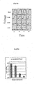
- FIG 8A shows the real time changes in voltage for individual wells.
- FIG. 9 demonstrates the use of the device to identify antagonists in a screening mode. The results show ratio vs well number for the assay run in antagonist screening mode. End ratio values were averaged as in FIG. 9 .
- a test antagonist 100 ⁇ M was used to test screening sensitivity. Vehicle control wells had an equivalent final concentration of DMSO as the test antagonist treated wells. Negative controls received an addition of buffer instead of agonist.
- cells HEK-293 were washed with assay buffer (160mM NaCl, 10 mM HEPES, pH 7.4, 0.34 mM Na 2 HPO 4 , 0.4 mM MgCl 2 , 0.5 mM KH 2 PO 4 , 5.37 mM KCl, 1.26 mM CaCl 2 , 2g/L D-glucose) and loaded with the fluorescent dyes CC2-DMPF and DiSBAC 2 as described in Table 8.
- assay buffer 160mM NaCl, 10 mM HEPES, pH 7.4, 0.34 mM Na 2 HPO 4 , 0.4 mM MgCl 2 , 0.5 mM KH 2 PO 4 , 5.37 mM KCl, 1.26 mM CaCl 2 , 2g/L D-glucose
Landscapes
- Health & Medical Sciences (AREA)
- Pathology (AREA)
- Life Sciences & Earth Sciences (AREA)
- Immunology (AREA)
- Chemical & Material Sciences (AREA)
- Analytical Chemistry (AREA)
- Biochemistry (AREA)
- General Health & Medical Sciences (AREA)
- General Physics & Mathematics (AREA)
- Physics & Mathematics (AREA)
- Nuclear Medicine, Radiotherapy & Molecular Imaging (AREA)
- Investigating, Analyzing Materials By Fluorescence Or Luminescence (AREA)
- Testing Of Optical Devices Or Fibers (AREA)
- Analysing Materials By The Use Of Radiation (AREA)
- Other Investigation Or Analysis Of Materials By Electrical Means (AREA)
- Treatment Of Water By Ion Exchange (AREA)
- Sampling And Sample Adjustment (AREA)
- Optical Measuring Cells (AREA)
- Automatic Analysis And Handling Materials Therefor (AREA)
- Light Guides In General And Applications Therefor (AREA)
- Inspection Of Paper Currency And Valuable Securities (AREA)
- Alarm Systems (AREA)
- Burglar Alarm Systems (AREA)
Applications Claiming Priority (5)
| Application Number | Priority Date | Filing Date | Title |
|---|---|---|---|
| US118728 | 1998-07-17 | ||
| US09/118,728 US6608671B2 (en) | 1998-07-17 | 1998-07-17 | Detector and screening device for ion channels |
| US122544 | 1998-07-24 | ||
| US09/122,544 US6349160B2 (en) | 1998-07-24 | 1998-07-24 | Detector and screening device for ion channels |
| EP99113933A EP0973040B1 (fr) | 1998-07-17 | 1999-07-16 | Détecteur et dispositif de tamisage pour canaux ioniques |
Related Parent Applications (2)
| Application Number | Title | Priority Date | Filing Date |
|---|---|---|---|
| EP99113933.8 Division | 1999-07-16 | ||
| EP99113933A Division EP0973040B1 (fr) | 1998-07-17 | 1999-07-16 | Détecteur et dispositif de tamisage pour canaux ioniques |
Publications (2)
| Publication Number | Publication Date |
|---|---|
| EP1403645A1 true EP1403645A1 (fr) | 2004-03-31 |
| EP1403645B1 EP1403645B1 (fr) | 2007-09-12 |
Family
ID=26816682
Family Applications (2)
| Application Number | Title | Priority Date | Filing Date |
|---|---|---|---|
| EP99113933A Expired - Lifetime EP0973040B1 (fr) | 1998-07-17 | 1999-07-16 | Détecteur et dispositif de tamisage pour canaux ioniques |
| EP03027436A Expired - Lifetime EP1403645B1 (fr) | 1998-07-17 | 1999-07-16 | Détecteur et dispositif de tamisage pour canaux ioniques |
Family Applications Before (1)
| Application Number | Title | Priority Date | Filing Date |
|---|---|---|---|
| EP99113933A Expired - Lifetime EP0973040B1 (fr) | 1998-07-17 | 1999-07-16 | Détecteur et dispositif de tamisage pour canaux ioniques |
Country Status (10)
| Country | Link |
|---|---|
| EP (2) | EP0973040B1 (fr) |
| JP (1) | JP2002520615A (fr) |
| AT (2) | ATE373241T1 (fr) |
| AU (1) | AU5108199A (fr) |
| CA (1) | CA2278045A1 (fr) |
| DE (2) | DE69913257T2 (fr) |
| DK (1) | DK0973040T3 (fr) |
| ES (1) | ES2210911T3 (fr) |
| PT (1) | PT973040E (fr) |
| WO (1) | WO2000004366A1 (fr) |
Cited By (1)
| Publication number | Priority date | Publication date | Assignee | Title |
|---|---|---|---|---|
| CN110428193A (zh) * | 2019-06-14 | 2019-11-08 | 上海中旖能源科技有限公司 | 基于车辆轨迹数据的多模式液化天然气运输车辆筛选方法 |
Families Citing this family (24)
| Publication number | Priority date | Publication date | Assignee | Title |
|---|---|---|---|---|
| US6200762B1 (en) | 1997-08-01 | 2001-03-13 | Aurora Biosciences Corporation | Photon reducing agents and compositions for fluorescence assays |
| US6221612B1 (en) | 1997-08-01 | 2001-04-24 | Aurora Biosciences Corporation | Photon reducing agents for use in fluorescence assays |
| US6214563B1 (en) | 1997-08-01 | 2001-04-10 | Aurora Biosciences Corporation | Photon reducing agents for reducing undesired light emission in assays |
| US6519032B1 (en) * | 1998-04-03 | 2003-02-11 | Symyx Technologies, Inc. | Fiber optic apparatus and use thereof in combinatorial material science |
| GB9915034D0 (en) * | 1999-06-29 | 1999-08-25 | Cambridge Imaging Ltd | Improved assay analysis |
| DE69915468T2 (de) * | 1999-09-01 | 2005-01-20 | Invitrogen Corp., Carlsbad | Photon Dämpfer für Fluoreszenzassays |
| US6784982B1 (en) | 1999-11-04 | 2004-08-31 | Regents Of The University Of Minnesota | Direct mapping of DNA chips to detector arrays |
| US6867851B2 (en) | 1999-11-04 | 2005-03-15 | Regents Of The University Of Minnesota | Scanning of biological samples |
| EP1250589A1 (fr) | 1999-12-11 | 2002-10-23 | Metso Paper Automation OY | Dispositif de detection des caracteristiques d'une bande papier defilante |
| WO2002093144A1 (fr) * | 2001-05-10 | 2002-11-21 | Regents Of The University Of Minnesota | Imagerie d'echantillons biologiques au moyen d'un photodetecteur electronique |
| CA2453489A1 (fr) | 2001-07-12 | 2003-01-23 | Merck & Co., Inc. | Stimulation du champ electrique de cellules eucaryotes |
| EP1506390B1 (fr) | 2002-05-17 | 2011-12-14 | Life Technologies Corporation | Appareil et procede pour differencier par longueur d'onde d'excitation des signaux de fluorescence multiples |
| DE10322443A1 (de) * | 2003-05-19 | 2004-12-30 | PRO DESIGN Gesellschaft für Produktentwicklung mbH | Multifunktioneller Reader für Biochips |
| ITMI20050114A1 (it) * | 2005-01-27 | 2006-07-28 | Milano Politecnico | Apparato e metodo per la stimolazione e la rilevazione ottica in maniera non invasiva dell'attivita' elettrica di almeno una cellula |
| EP1896831B1 (fr) | 2005-06-27 | 2013-04-10 | THE GOVERNMENT OF THE UNITED STATES OF AMERICA, represented by THE SECRETARY, DEPARTMENT OF HEALTH AND HUMAN SERVICES | Système de détection de fluorescence multicolore à optique fixe et à sélectivité spatiale pour dispositif microfluidique à canaux multiples et procédé de détection |
| DE102007047093B4 (de) * | 2007-10-01 | 2010-07-01 | Ferton Holding S.A. | Vorrichtung zur Messung von Fluoreszenzstrahlung an biologischen Substanzen mit einer Halbleitersensorenanordnung |
| AU2009288657A1 (en) | 2008-09-04 | 2010-03-11 | Galenea Corp. | Synaptic vesicle cycling assays and systems |
| DE102010016382B4 (de) * | 2010-04-09 | 2022-06-02 | Leica Microsystems Cms Gmbh | Fluoreszenzmikroskop und Verfahren zur Durchführung von Multipositionierungen in einer Screening-Applikation |
| JP5420725B2 (ja) * | 2011-06-28 | 2014-02-19 | 株式会社イマック | 光学測定装置 |
| DE102011108180B4 (de) | 2011-07-20 | 2014-12-24 | Sensor Instruments Entwicklungs- Und Vertriebs Gmbh | Verfahren und Vorrichtung zum Identifizieren eines photolumineszierenden Materials |
| US9182336B2 (en) * | 2012-03-02 | 2015-11-10 | Laxco, Inc. | Multichannel analytical instruments for use with specimen holders |
| US9387451B2 (en) | 2014-02-03 | 2016-07-12 | International Business Machines Corporation | Flow cell array and uses thereof |
| DE102016200271A1 (de) * | 2016-01-13 | 2017-07-13 | Institut Dr. Foerster Gmbh & Co. Kg | Vorrichtung zur Erzeugung und Messung einer Emission |
| WO2021170364A1 (fr) * | 2020-02-26 | 2021-09-02 | Robert Bosch Gmbh | Support de filtre optique pour un dispositif d'analyte biologique |
Citations (6)
| Publication number | Priority date | Publication date | Assignee | Title |
|---|---|---|---|---|
| US3905852A (en) * | 1972-12-19 | 1975-09-16 | Nippon Glass Fiber Co Ltd | Method of producing branched photo-conductive fiber bundles |
| DE3036638A1 (de) * | 1980-09-29 | 1982-04-29 | Vanzetti Infrared & Computer Systems, Inc., Canton, Mass. | Bandverhaeltnis-radiometer |
| EP0230679A1 (fr) * | 1986-01-30 | 1987-08-05 | The Dow Chemical Company | Sonde à fibres-optiques |
| FR2661986A1 (fr) * | 1990-05-14 | 1991-11-15 | Commissariat Energie Atomique | Appareil autonome de lecture d'un capteur chimique actif a au moins une fibre optique et procede pour sa mise en óoeuvre. |
| US5086220A (en) * | 1991-02-05 | 1992-02-04 | The Babcock & Wilcox Company | Radiation imaging fiber optic temperature distribution monitor |
| US5670113A (en) * | 1991-12-20 | 1997-09-23 | Sibia Neurosciences, Inc. | Automated analysis equipment and assay method for detecting cell surface protein and/or cytoplasmic receptor function using same |
Family Cites Families (5)
| Publication number | Priority date | Publication date | Assignee | Title |
|---|---|---|---|---|
| FR2567538B1 (fr) * | 1984-07-12 | 1986-12-26 | Inst Nat Sante Rech Med | Automate pour l'analyse et le clonage de cultures cellulaires ainsi que pour l'analyse bacteriologique |
| CA2015941A1 (fr) * | 1989-05-03 | 1990-11-03 | Marsha A. Kessler | Methode d'agglutination des echantillons de sang |
| US5217285A (en) * | 1991-03-15 | 1993-06-08 | The United States Of America As Represented By United States Department Of Energy | Apparatus for synthesis of a solar spectrum |
| JP2912957B2 (ja) * | 1991-06-18 | 1999-06-28 | 東ソー株式会社 | 酵素活性測定方法及び装置 |
| US5436718A (en) * | 1993-07-30 | 1995-07-25 | Biolumin Corporation | Mutli-functional photometer with movable linkage for routing optical fibers |
-
1999
- 1999-07-16 DE DE69913257T patent/DE69913257T2/de not_active Expired - Lifetime
- 1999-07-16 EP EP99113933A patent/EP0973040B1/fr not_active Expired - Lifetime
- 1999-07-16 EP EP03027436A patent/EP1403645B1/fr not_active Expired - Lifetime
- 1999-07-16 AU AU51081/99A patent/AU5108199A/en not_active Abandoned
- 1999-07-16 WO PCT/US1999/016170 patent/WO2000004366A1/fr active Application Filing
- 1999-07-16 AT AT03027436T patent/ATE373241T1/de not_active IP Right Cessation
- 1999-07-16 JP JP2000560434A patent/JP2002520615A/ja active Pending
- 1999-07-16 DK DK99113933T patent/DK0973040T3/da active
- 1999-07-16 DE DE69937126T patent/DE69937126T2/de not_active Expired - Lifetime
- 1999-07-16 AT AT99113933T patent/ATE255727T1/de not_active IP Right Cessation
- 1999-07-16 ES ES99113933T patent/ES2210911T3/es not_active Expired - Lifetime
- 1999-07-16 PT PT99113933T patent/PT973040E/pt unknown
- 1999-07-19 CA CA002278045A patent/CA2278045A1/fr not_active Abandoned
Patent Citations (6)
| Publication number | Priority date | Publication date | Assignee | Title |
|---|---|---|---|---|
| US3905852A (en) * | 1972-12-19 | 1975-09-16 | Nippon Glass Fiber Co Ltd | Method of producing branched photo-conductive fiber bundles |
| DE3036638A1 (de) * | 1980-09-29 | 1982-04-29 | Vanzetti Infrared & Computer Systems, Inc., Canton, Mass. | Bandverhaeltnis-radiometer |
| EP0230679A1 (fr) * | 1986-01-30 | 1987-08-05 | The Dow Chemical Company | Sonde à fibres-optiques |
| FR2661986A1 (fr) * | 1990-05-14 | 1991-11-15 | Commissariat Energie Atomique | Appareil autonome de lecture d'un capteur chimique actif a au moins une fibre optique et procede pour sa mise en óoeuvre. |
| US5086220A (en) * | 1991-02-05 | 1992-02-04 | The Babcock & Wilcox Company | Radiation imaging fiber optic temperature distribution monitor |
| US5670113A (en) * | 1991-12-20 | 1997-09-23 | Sibia Neurosciences, Inc. | Automated analysis equipment and assay method for detecting cell surface protein and/or cytoplasmic receptor function using same |
Cited By (2)
| Publication number | Priority date | Publication date | Assignee | Title |
|---|---|---|---|---|
| CN110428193A (zh) * | 2019-06-14 | 2019-11-08 | 上海中旖能源科技有限公司 | 基于车辆轨迹数据的多模式液化天然气运输车辆筛选方法 |
| CN110428193B (zh) * | 2019-06-14 | 2022-03-04 | 上海中旖能源科技有限公司 | 基于车辆轨迹数据的多模式液化天然气运输车辆筛选方法 |
Also Published As
| Publication number | Publication date |
|---|---|
| AU5108199A (en) | 2000-02-07 |
| JP2002520615A (ja) | 2002-07-09 |
| EP0973040B1 (fr) | 2003-12-03 |
| WO2000004366A1 (fr) | 2000-01-27 |
| EP0973040A3 (fr) | 2000-03-15 |
| DE69937126T2 (de) | 2008-06-12 |
| DE69937126D1 (de) | 2007-10-25 |
| DE69913257T2 (de) | 2004-09-02 |
| ES2210911T3 (es) | 2004-07-01 |
| WO2000004366A9 (fr) | 2000-06-02 |
| EP0973040A2 (fr) | 2000-01-19 |
| DE69913257D1 (de) | 2004-01-15 |
| CA2278045A1 (fr) | 2000-01-17 |
| PT973040E (pt) | 2004-04-30 |
| EP1403645B1 (fr) | 2007-09-12 |
| ATE255727T1 (de) | 2003-12-15 |
| ATE373241T1 (de) | 2007-09-15 |
| DK0973040T3 (da) | 2004-03-29 |
Similar Documents
| Publication | Publication Date | Title |
|---|---|---|
| US7142290B2 (en) | Detector and screening device for ion channels | |
| EP1403645B1 (fr) | Détecteur et dispositif de tamisage pour canaux ioniques | |
| US6349160B2 (en) | Detector and screening device for ion channels | |
| US6071748A (en) | Light detection device | |
| US6488892B1 (en) | Sample-holding devices and systems | |
| US6310687B1 (en) | Light detection device with means for tracking sample sites | |
| US6982431B2 (en) | Sample analysis systems | |
| US6097025A (en) | Light detection device having an optical-path switching mechanism | |
| US6825921B1 (en) | Multi-mode light detection system | |
| US7551271B2 (en) | Uncaging devices | |
| US6750457B2 (en) | System for high throughput analysis | |
| US6469311B1 (en) | Detection device for light transmitted from a sensed volume | |
| WO1998049543A1 (fr) | Systeme de detection optique a balayage | |
| EP1704403B1 (fr) | Lecteur multimode | |
| EP1032813A2 (fr) | Appareil et procedes permettant de mesurer la polarisation de fluorescence |
Legal Events
| Date | Code | Title | Description |
|---|---|---|---|
| PUAI | Public reference made under article 153(3) epc to a published international application that has entered the european phase |
Free format text: ORIGINAL CODE: 0009012 |
|
| 17P | Request for examination filed |
Effective date: 20031128 |
|
| AC | Divisional application: reference to earlier application |
Ref document number: 0973040 Country of ref document: EP Kind code of ref document: P |
|
| AK | Designated contracting states |
Kind code of ref document: A1 Designated state(s): AT BE CH CY DE DK ES FI FR GB GR IE IT LI LU MC NL PT SE |
|
| AKX | Designation fees paid |
Designated state(s): AT BE CH CY DE DK ES FI FR GB GR IE IT LI LU MC NL PT SE |
|
| GRAP | Despatch of communication of intention to grant a patent |
Free format text: ORIGINAL CODE: EPIDOSNIGR1 |
|
| GRAS | Grant fee paid |
Free format text: ORIGINAL CODE: EPIDOSNIGR3 |
|
| GRAA | (expected) grant |
Free format text: ORIGINAL CODE: 0009210 |
|
| AC | Divisional application: reference to earlier application |
Ref document number: 0973040 Country of ref document: EP Kind code of ref document: P |
|
| AK | Designated contracting states |
Kind code of ref document: B1 Designated state(s): AT BE CH CY DE DK ES FI FR GB GR IE IT LI LU MC NL PT SE |
|
| REG | Reference to a national code |
Ref country code: GB Ref legal event code: FG4D |
|
| RIN1 | Information on inventor provided before grant (corrected) |
Inventor name: VUONG, MINH Inventor name: TSIEN, ROGER Y. Inventor name: PHAM, ANDREW A. Inventor name: COASSIN, PETER J. Inventor name: HAROOTUNIAN, ALEC TATE |
|
| REG | Reference to a national code |
Ref country code: CH Ref legal event code: EP |
|
| REF | Corresponds to: |
Ref document number: 69937126 Country of ref document: DE Date of ref document: 20071025 Kind code of ref document: P |
|
| REG | Reference to a national code |
Ref country code: IE Ref legal event code: FG4D |
|
| ET | Fr: translation filed | ||
| REG | Reference to a national code |
Ref country code: CH Ref legal event code: NV Representative=s name: RITSCHER & PARTNER AG |
|
| PG25 | Lapsed in a contracting state [announced via postgrant information from national office to epo] |
Ref country code: FI Free format text: LAPSE BECAUSE OF FAILURE TO SUBMIT A TRANSLATION OF THE DESCRIPTION OR TO PAY THE FEE WITHIN THE PRESCRIBED TIME-LIMIT Effective date: 20070912 |
|
| PG25 | Lapsed in a contracting state [announced via postgrant information from national office to epo] |
Ref country code: AT Free format text: LAPSE BECAUSE OF FAILURE TO SUBMIT A TRANSLATION OF THE DESCRIPTION OR TO PAY THE FEE WITHIN THE PRESCRIBED TIME-LIMIT Effective date: 20070912 |
|
| NLV1 | Nl: lapsed or annulled due to failure to fulfill the requirements of art. 29p and 29m of the patents act | ||
| PG25 | Lapsed in a contracting state [announced via postgrant information from national office to epo] |
Ref country code: BE Free format text: LAPSE BECAUSE OF FAILURE TO SUBMIT A TRANSLATION OF THE DESCRIPTION OR TO PAY THE FEE WITHIN THE PRESCRIBED TIME-LIMIT Effective date: 20070912 |
|
| REG | Reference to a national code |
Ref country code: CH Ref legal event code: PCAR Free format text: RITSCHER & PARTNER AG;RESIRAIN 1;8125 ZOLLIKERBERG (CH) |
|
| PG25 | Lapsed in a contracting state [announced via postgrant information from national office to epo] |
Ref country code: NL Free format text: LAPSE BECAUSE OF FAILURE TO SUBMIT A TRANSLATION OF THE DESCRIPTION OR TO PAY THE FEE WITHIN THE PRESCRIBED TIME-LIMIT Effective date: 20070912 Ref country code: ES Free format text: LAPSE BECAUSE OF FAILURE TO SUBMIT A TRANSLATION OF THE DESCRIPTION OR TO PAY THE FEE WITHIN THE PRESCRIBED TIME-LIMIT Effective date: 20071223 Ref country code: GR Free format text: LAPSE BECAUSE OF FAILURE TO SUBMIT A TRANSLATION OF THE DESCRIPTION OR TO PAY THE FEE WITHIN THE PRESCRIBED TIME-LIMIT Effective date: 20071213 |
|
| PG25 | Lapsed in a contracting state [announced via postgrant information from national office to epo] |
Ref country code: PT Free format text: LAPSE BECAUSE OF FAILURE TO SUBMIT A TRANSLATION OF THE DESCRIPTION OR TO PAY THE FEE WITHIN THE PRESCRIBED TIME-LIMIT Effective date: 20080212 |
|
| PG25 | Lapsed in a contracting state [announced via postgrant information from national office to epo] |
Ref country code: SE Free format text: LAPSE BECAUSE OF FAILURE TO SUBMIT A TRANSLATION OF THE DESCRIPTION OR TO PAY THE FEE WITHIN THE PRESCRIBED TIME-LIMIT Effective date: 20071212 |
|
| PLBE | No opposition filed within time limit |
Free format text: ORIGINAL CODE: 0009261 |
|
| STAA | Information on the status of an ep patent application or granted ep patent |
Free format text: STATUS: NO OPPOSITION FILED WITHIN TIME LIMIT |
|
| PG25 | Lapsed in a contracting state [announced via postgrant information from national office to epo] |
Ref country code: DK Free format text: LAPSE BECAUSE OF FAILURE TO SUBMIT A TRANSLATION OF THE DESCRIPTION OR TO PAY THE FEE WITHIN THE PRESCRIBED TIME-LIMIT Effective date: 20070912 |
|
| 26N | No opposition filed |
Effective date: 20080613 |
|
| PG25 | Lapsed in a contracting state [announced via postgrant information from national office to epo] |
Ref country code: MC Free format text: LAPSE BECAUSE OF NON-PAYMENT OF DUE FEES Effective date: 20080731 |
|
| PG25 | Lapsed in a contracting state [announced via postgrant information from national office to epo] |
Ref country code: CY Free format text: LAPSE BECAUSE OF FAILURE TO SUBMIT A TRANSLATION OF THE DESCRIPTION OR TO PAY THE FEE WITHIN THE PRESCRIBED TIME-LIMIT Effective date: 20070912 Ref country code: IE Free format text: LAPSE BECAUSE OF NON-PAYMENT OF DUE FEES Effective date: 20080716 |
|
| PG25 | Lapsed in a contracting state [announced via postgrant information from national office to epo] |
Ref country code: LU Free format text: LAPSE BECAUSE OF NON-PAYMENT OF DUE FEES Effective date: 20080716 |
|
| PG25 | Lapsed in a contracting state [announced via postgrant information from national office to epo] |
Ref country code: IT Free format text: LAPSE BECAUSE OF NON-PAYMENT OF DUE FEES Effective date: 20080731 |
|
| REG | Reference to a national code |
Ref country code: CH Ref legal event code: PFA Owner name: VERTEX PHARMACEUTICALS (SAN DIEGO) LLC, US Free format text: FORMER OWNER: VERTEX PHARMACEUTICALS (SAN DIEGO) LLC, US |
|
| REG | Reference to a national code |
Ref country code: FR Ref legal event code: PLFP Year of fee payment: 18 |
|
| REG | Reference to a national code |
Ref country code: FR Ref legal event code: PLFP Year of fee payment: 19 |
|
| PGFP | Annual fee paid to national office [announced via postgrant information from national office to epo] |
Ref country code: CH Payment date: 20170727 Year of fee payment: 19 Ref country code: GB Payment date: 20170727 Year of fee payment: 19 Ref country code: FR Payment date: 20170726 Year of fee payment: 19 Ref country code: DE Payment date: 20170727 Year of fee payment: 19 |
|
| REG | Reference to a national code |
Ref country code: DE Ref legal event code: R119 Ref document number: 69937126 Country of ref document: DE |
|
| REG | Reference to a national code |
Ref country code: CH Ref legal event code: PL |
|
| GBPC | Gb: european patent ceased through non-payment of renewal fee |
Effective date: 20180716 |
|
| PG25 | Lapsed in a contracting state [announced via postgrant information from national office to epo] |
Ref country code: FR Free format text: LAPSE BECAUSE OF NON-PAYMENT OF DUE FEES Effective date: 20180731 Ref country code: GB Free format text: LAPSE BECAUSE OF NON-PAYMENT OF DUE FEES Effective date: 20180716 Ref country code: CH Free format text: LAPSE BECAUSE OF NON-PAYMENT OF DUE FEES Effective date: 20180731 Ref country code: LI Free format text: LAPSE BECAUSE OF NON-PAYMENT OF DUE FEES Effective date: 20180731 Ref country code: DE Free format text: LAPSE BECAUSE OF NON-PAYMENT OF DUE FEES Effective date: 20190201 |