EP1403544A2 - Lamellenkupplung - Google Patents
Lamellenkupplung Download PDFInfo
- Publication number
- EP1403544A2 EP1403544A2 EP03020345A EP03020345A EP1403544A2 EP 1403544 A2 EP1403544 A2 EP 1403544A2 EP 03020345 A EP03020345 A EP 03020345A EP 03020345 A EP03020345 A EP 03020345A EP 1403544 A2 EP1403544 A2 EP 1403544A2
- Authority
- EP
- European Patent Office
- Prior art keywords
- clutch
- center
- fitted
- center boss
- notches
- Prior art date
- Legal status (The legal status is an assumption and is not a legal conclusion. Google has not performed a legal analysis and makes no representation as to the accuracy of the status listed.)
- Granted
Links
Images


Classifications
-
- F—MECHANICAL ENGINEERING; LIGHTING; HEATING; WEAPONS; BLASTING
- F16—ENGINEERING ELEMENTS AND UNITS; GENERAL MEASURES FOR PRODUCING AND MAINTAINING EFFECTIVE FUNCTIONING OF MACHINES OR INSTALLATIONS; THERMAL INSULATION IN GENERAL
- F16D—COUPLINGS FOR TRANSMITTING ROTATION; CLUTCHES; BRAKES
- F16D13/00—Friction clutches
- F16D13/58—Details
- F16D13/60—Clutching elements
- F16D13/64—Clutch-plates; Clutch-lamellae
- F16D13/68—Attachments of plates or lamellae to their supports
- F16D13/683—Attachments of plates or lamellae to their supports for clutches with multiple lamellae
Definitions
- the present invention relates to a multiple-disc clutch for interrupting transmission of power from an input shaft to a driven shaft.
- a clutch outer is divided into a base unit and an outer unit. These are resiliently coupled via resilient members composed of rubber etc. so that when a clutch outer is subjected to impact force, this impact can be absorbed.
- the clutch inner is also divided into two members of an inner and outer member. The inner member and the outer member are resiliently coupled as a result of resilient members constituted by rubber material etc. being sandwiched between projections projecting in mutually different manners from the facing surfaces of each of the inner and outer members so that when the clutch inner is subjected to shocks, such shocks can be absorbed (for example, refer to patent document 1).
- a multiple-disc clutch comprising a clutch outer, coupled using an input shaft and gears so as to rotate, and being fitted in such a manner that a plurality of friction plates are capable of sliding in an axial direction at an inner surface of a cylindrical part, a clutch inner spline-fitted to a driven shaft and fitted in a slideable manner in the axial direction so that a plurality of clutch discs provided on the outer surface of a cylindrical part alternately overlap with the friction plates and means for closely pressing the friction plates and the clutch discs together, the clutch inner comprising a center boss, a clutch center, and resilient shock-absorbing members, the center boss being equipped with a tubular part spline-fitted to the driven shaft, projections having radial-shaped notches formed in a thick-walled disc shape at an end of the tubular part, and plate-shaped projections formed at the center part of the tubular part, extending radially along a plane passing through an axial line
- the present invention is capable of using a resilient shock member with a large capacity and can possess a stopper function between a center boss notch at a position with a large radius and a clutch center stopper.
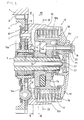
- FIG. 1 is a vertical cross-section showing the essential parts of a power unit for a motorcycle by cutting away at a plane passing through a crank shaft 1 and a main shaft 2
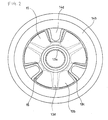
- FIG. 2 is view taken along II-II of FIG. 1
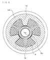
- FIG. 3 is a lateral cross-section taken along III-III of FIG. 1
- FIG. 4 is a lateral cross-section taken along IV-IV of FIG. 1.
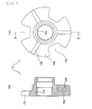
- FIG. 5 is a view showing a center boss of a clutch inner of FIG. 1 extracted, where FIG. 5(a) is a side view and FIG. 5(b) is a vertical cross-section taken along B-B of FIG. 5(a), FIG.
- FIG. 6 is a view showing the clutch center of the clutch inner extracted, where FIG. 6(a) is a side view and FIG. 6(b) is a vertical cross-section taken along B-B of FIG. 6(a), and FIG. 7 is a side view showing resilient shock-absorbing material of the clutch inner extracted.
- a primary drive gear 3 is formed at a crank shaft 1 taken as an input shaft, and a primary driven gear 4 normally meshing with the primary drive gear 3 is fitted to the main shaft 2 taken as a driven shaft so as to be relatively rotatable in a circumferential direction with respect to the shaft.
- a gear 5 is arranged next to the primary driven gear 4.
- a multiple-disc clutch 9 comprised of a clutch outer 10, a clutch inner 12 and an operating mechanism 17 is provided at an end of the main shaft 2.
- a disc part 10a and cylindrical part 10b are formed at the clutch outer 10, with the disc part 10a being fitted to the primary driven gear 4, the gear 5 via a resilient shock-absorbing member 6 and resilient shock-absorbing member 7. Further, a plurality of friction plates 11 are fitted at the inner surface of the cylindrical part 10b so as to be capable of sliding in an axial direction.
- the clutch inner 12 of this embodiment comprises a center boss 13, clutch center 14, and resilient shock-absorbing members 15.
- the center boss 13 is spline-fitted to the main shaft 2 and a cylindrical part 14b is formed at the outer part of the clutch center 14.
- a plurality of clutch discs 16 are fitted at the outer surface of the cylindrical part 14b so as to alternately overlap with the friction plates 11 and be capable of sliding in the axial direction.
- a thrusting plate 18 is provided on the outside of the friction plates 11 and the clutch discs 16.
- the thrusting plate 18 presses the plurality of friction plates 11 and clutch discs 16 closely together due to the spring force of a clutch spring 21 fitted using a bolt 19 and a washer 20 to a spring fitting part 14c projecting outwards from a central part 14a of the clutch center 14 in a direction parallel to an axial line so as to generate frictional force.
- the clutch center 14 of the clutch inner 12 rotates integrally with the clutch outer 10.
- the multiple-disc clutch 9 is in a connected state and rotation of the crank shaft 1 is transmitted to the main shaft 2.
- an urging rod 22 is inserted into the axial center of the main shaft 2 so that a central member 23 resists the force of the clutch spring 21 so as to move towards the right in the drawing, so that the thrusting plate 18 floats from the friction plates 11. In doing so, the connecting of the clutch outer 10 and the clutch inner 12 is broken.
- the urging rod 22 may also be operated manually using, for example, a mechanism fitted to the handle of the vehicle.
- FIG. 2 through to FIG. 7 a description is given of the structure of a clutch inner 12.
- a tubular part 13a spline-fitted to the main shaft 2 as described previously
- a projection 13b having a plurality of notches 13c (three in the example in the drawings) formed in the thick-walled disc shape at the end (the left end in FIG. 5(b)) of the tubular part 13a
- plate-shaped projections 13d extending radially along a plane passing through an axial line at the center of the notches 13c formed at a central part of the tubular part 13a are provided at the center boss 13.
- the clutch center 14 is equipped with the central part 14a fitting to the end part (left end in FIG. 5(b)) of the tubular part 13a of the center. boss 13 and stoppers 14d extending to within the notch 13c of the center boss 13 (refer to FIG. 2 to FIG. 4).
- the reason why the cylindrical part 14b to which the clutch discs 16 are fitted is on the outside and the reason the spring fitting part 14c to which the bolt 19, washer 20, and clutch spring 21 are fitted projects from the end part is as described below.
- the resilient shock-absorbing members 15 are made from a resilient material such as rubber, and as shown by the solid lines in FIG. 7, groups of two are mutually connected by fine fibrous coupling members 15a of the same resilient material.
- the center boss 13, clutch center 14 and resilient shock-absorbing member 15 are assembled and connected as shown in FIG. 1 to FIG. 4 so as to form the clutch inner 12. Namely, the central part 14a of the clutch center 14 engages with the end of the tubular part 13a of the center boss 13. In doing so, the stoppers 14d of the clutch center14 advance to between the plate-shaped projections 13d at the notches 13c formed in the projections 13b of the center boss 13. Further, a blank space between the plate-shaped projections 13d of the center boss 13 and the stoppers 14d is filled with the resilient shock-absorbing member 15. Neighboring projections 13b beyond the stoppers 14d are coupled to each other with coupling members 15a.
- a slight gap is provided at this time between the inner surfaces of the notches 13c of the projections 13b and the outer surfaces of the stoppers 14d of the clutch center 14.
- the center boss 13 and the clutch center 14 are therefore allowed to rock slightly with respect to each other about the shaft due to compression of the resilient shock-absorbing member 15.
- the shock-absorbing load with respect to the clutch inner 12 is first received by the resilient shock-absorbing member 15, but when the load is greater than the capacity of the resilient shock-absorbing member 15, force is transmitted as a result of contact between the inner surfaces of the notches 13c of the projections 13b.
- a large capacity resilient shock-absorbing member 15 is provided between the center boss 13 of the clutch inner 12 and the clutch center 14. Therefore, even if the clutch inner 12 is subjected to a substantial shock, the force of such a shock can be effectively absorbed. Further, by utilizing contact between notches 13c of projections 13b provided on a center boss 13 and stoppers 14d provided on a clutch center 14 as a stopper for stopping relative rocking motion of the center boss 13 and the clutch center 14 within a predetermined limitation, the radius of contact locations and the contact surface area can be made large and the force exerted on the stoppers can be made small so as to further improve the effectiveness of shock absorption.
- crank shaft 1 main shaft 2, primary drive gear 3, primary driven gear 4, gear 5, resilient shock-absorbing member 6, 7, multiple-disc clutch 9, clutch outer 10, disc part 10a, cylindrical part 10b, friction plates 11, clutch inner 12, center boss 13, tubular part 13a, projections 13b, notches 13c, plate-shaped projections 13d, clutch center 14, central part 14a, cylindrical part 14b, spring fitting part 14c, stoppers 14d, resilient shock-absorbing member 15, coupling members 15a, clutch discs 16, operating mechanism 17, thrusting plate 18, bolt 19, washer 20, clutch spring 21, urging rod 22, central member 23.
Landscapes
- Engineering & Computer Science (AREA)
- General Engineering & Computer Science (AREA)
- Mechanical Engineering (AREA)
- Mechanical Operated Clutches (AREA)
Applications Claiming Priority (2)
| Application Number | Priority Date | Filing Date | Title |
|---|---|---|---|
| JP2002283509A JP3933551B2 (ja) | 2002-09-27 | 2002-09-27 | 多板式クラッチ |
| JP2002283509 | 2002-09-27 |
Publications (3)
| Publication Number | Publication Date |
|---|---|
| EP1403544A2 true EP1403544A2 (de) | 2004-03-31 |
| EP1403544A3 EP1403544A3 (de) | 2004-08-25 |
| EP1403544B1 EP1403544B1 (de) | 2010-12-22 |
Family
ID=31973354
Family Applications (1)
| Application Number | Title | Priority Date | Filing Date |
|---|---|---|---|
| EP03020345A Expired - Fee Related EP1403544B1 (de) | 2002-09-27 | 2003-09-09 | Lamellenkupplung |
Country Status (3)
| Country | Link |
|---|---|
| EP (1) | EP1403544B1 (de) |
| JP (1) | JP3933551B2 (de) |
| DE (1) | DE60335433D1 (de) |
Cited By (2)
| Publication number | Priority date | Publication date | Assignee | Title |
|---|---|---|---|---|
| US8297423B2 (en) | 2006-09-29 | 2012-10-30 | Honda Motor Co., Ltd. | Twin clutch apparatus |
| CN112145744A (zh) * | 2015-12-07 | 2020-12-29 | 浙江三花制冷集团有限公司 | 一种传动连接结构及具有该传动连接结构的电动阀 |
Families Citing this family (5)
| Publication number | Priority date | Publication date | Assignee | Title |
|---|---|---|---|---|
| JP2007321862A (ja) * | 2006-05-31 | 2007-12-13 | Hitachi Ltd | 電動ディスクブレーキ |
| JP4797008B2 (ja) * | 2007-09-26 | 2011-10-19 | 本田技研工業株式会社 | 多板クラッチ |
| JP5074230B2 (ja) * | 2008-02-20 | 2012-11-14 | 本田技研工業株式会社 | 多板クラッチ |
| JP5377459B2 (ja) * | 2010-11-05 | 2013-12-25 | 本田技研工業株式会社 | 多板クラッチ装置 |
| JP7398501B2 (ja) * | 2022-03-30 | 2023-12-14 | 本田技研工業株式会社 | 多板式摩擦クラッチ |
Citations (1)
| Publication number | Priority date | Publication date | Assignee | Title |
|---|---|---|---|---|
| JPH02570A (ja) | 1987-10-30 | 1990-01-05 | Toyo Ink Mfg Co Ltd | 光学記録媒体 |
Family Cites Families (2)
| Publication number | Priority date | Publication date | Assignee | Title |
|---|---|---|---|---|
| JP3378097B2 (ja) * | 1994-09-29 | 2003-02-17 | 本田技研工業株式会社 | 摩擦クラッチ |
| JP4179694B2 (ja) * | 1999-02-08 | 2008-11-12 | 本田技研工業株式会社 | ダンパスプリングを有するクラッチ |
-
2002
- 2002-09-27 JP JP2002283509A patent/JP3933551B2/ja not_active Expired - Lifetime
-
2003
- 2003-09-09 EP EP03020345A patent/EP1403544B1/de not_active Expired - Fee Related
- 2003-09-09 DE DE60335433T patent/DE60335433D1/de not_active Expired - Lifetime
Patent Citations (1)
| Publication number | Priority date | Publication date | Assignee | Title |
|---|---|---|---|---|
| JPH02570A (ja) | 1987-10-30 | 1990-01-05 | Toyo Ink Mfg Co Ltd | 光学記録媒体 |
Cited By (2)
| Publication number | Priority date | Publication date | Assignee | Title |
|---|---|---|---|---|
| US8297423B2 (en) | 2006-09-29 | 2012-10-30 | Honda Motor Co., Ltd. | Twin clutch apparatus |
| CN112145744A (zh) * | 2015-12-07 | 2020-12-29 | 浙江三花制冷集团有限公司 | 一种传动连接结构及具有该传动连接结构的电动阀 |
Also Published As
| Publication number | Publication date |
|---|---|
| EP1403544B1 (de) | 2010-12-22 |
| JP2004116723A (ja) | 2004-04-15 |
| JP3933551B2 (ja) | 2007-06-20 |
| EP1403544A3 (de) | 2004-08-25 |
| DE60335433D1 (de) | 2011-02-03 |
Similar Documents
| Publication | Publication Date | Title |
|---|---|---|
| CN110454513B (zh) | 动力传递装置 | |
| JP5254023B2 (ja) | トルク伝達用のカップリング装置 | |
| JP4990254B2 (ja) | 多板式クラッチ | |
| JP5502507B2 (ja) | 動力伝達装置 | |
| KR101080103B1 (ko) | 댐퍼 기구 | |
| KR20120053002A (ko) | 개선된 토크 용량과 토크 밀도를 가지는 차동장치 | |
| EP0209314B1 (de) | Kupplungsscheibe mit Dämpfung zur Spielbeseitigung | |
| EP1403544B1 (de) | Lamellenkupplung | |
| EP0151338B1 (de) | Kupplung mit Plattenanordnung | |
| CN101260909B (zh) | 具有扭力弹簧的联轴器装置 | |
| CA1221323A (en) | Torsional vibration absorbing system for vehicle transmission | |
| EP0209316A1 (de) | Kupplungsscheibe mit zweiteiliger Nabe | |
| US20120067146A1 (en) | Power unit for vehicle | |
| WO2024009760A1 (ja) | クラッチ装置および自動二輪車 | |
| WO2024004365A1 (ja) | クラッチ装置および自動二輪車 | |
| CN103216572A (zh) | 带有集成的减振系统的传递单元 | |
| JP2002195290A (ja) | 多板クラッチ装置 | |
| JP5324345B2 (ja) | 動力伝達装置 | |
| GB2128272A (en) | Friction clutch with power take-off | |
| WO2024009771A1 (ja) | クラッチ装置 | |
| JP7288975B2 (ja) | 変速機 | |
| JPH0735150A (ja) | 動力伝達装置の弾性継手 | |
| KR0153080B1 (ko) | 일체로 형성된 맞물림 및 해방레버와 압력판 부재를 갖는 클러치 장치 | |
| JP3209324B2 (ja) | 多板クラッチの打音防止構造 | |
| RU12846U1 (ru) | Сцепление |
Legal Events
| Date | Code | Title | Description |
|---|---|---|---|
| PUAI | Public reference made under article 153(3) epc to a published international application that has entered the european phase |
Free format text: ORIGINAL CODE: 0009012 |
|
| AK | Designated contracting states |
Kind code of ref document: A2 Designated state(s): AT BE BG CH CY CZ DE DK EE ES FI FR GB GR HU IE IT LI LU MC NL PT RO SE SI SK TR |
|
| AX | Request for extension of the european patent |
Extension state: AL LT LV MK |
|
| PUAL | Search report despatched |
Free format text: ORIGINAL CODE: 0009013 |
|
| AK | Designated contracting states |
Kind code of ref document: A3 Designated state(s): AT BE BG CH CY CZ DE DK EE ES FI FR GB GR HU IE IT LI LU MC NL PT RO SE SI SK TR |
|
| AX | Request for extension of the european patent |
Extension state: AL LT LV MK |
|
| 17P | Request for examination filed |
Effective date: 20050125 |
|
| AKX | Designation fees paid |
Designated state(s): DE FR GB IT |
|
| RBV | Designated contracting states (corrected) |
Designated state(s): DE FR GB IT |
|
| GRAP | Despatch of communication of intention to grant a patent |
Free format text: ORIGINAL CODE: EPIDOSNIGR1 |
|
| RAP1 | Party data changed (applicant data changed or rights of an application transferred) |
Owner name: HONDA GIKEN KOGYO KABUSHIKI KAISHA |
|
| GRAS | Grant fee paid |
Free format text: ORIGINAL CODE: EPIDOSNIGR3 |
|
| GRAA | (expected) grant |
Free format text: ORIGINAL CODE: 0009210 |
|
| AK | Designated contracting states |
Kind code of ref document: B1 Designated state(s): DE FR GB IT |
|
| REG | Reference to a national code |
Ref country code: GB Ref legal event code: FG4D |
|
| REF | Corresponds to: |
Ref document number: 60335433 Country of ref document: DE Date of ref document: 20110203 Kind code of ref document: P |
|
| REG | Reference to a national code |
Ref country code: DE Ref legal event code: R096 Ref document number: 60335433 Country of ref document: DE Effective date: 20110203 |
|
| PLBE | No opposition filed within time limit |
Free format text: ORIGINAL CODE: 0009261 |
|
| STAA | Information on the status of an ep patent application or granted ep patent |
Free format text: STATUS: NO OPPOSITION FILED WITHIN TIME LIMIT |
|
| 26N | No opposition filed |
Effective date: 20110923 |
|
| PGFP | Annual fee paid to national office [announced via postgrant information from national office to epo] |
Ref country code: GB Payment date: 20110907 Year of fee payment: 9 Ref country code: FR Payment date: 20110922 Year of fee payment: 9 |
|
| REG | Reference to a national code |
Ref country code: DE Ref legal event code: R097 Ref document number: 60335433 Country of ref document: DE Effective date: 20110923 |
|
| REG | Reference to a national code |
Ref country code: DE Ref legal event code: R084 Ref document number: 60335433 Country of ref document: DE Effective date: 20120523 |
|
| GBPC | Gb: european patent ceased through non-payment of renewal fee |
Effective date: 20120909 |
|
| REG | Reference to a national code |
Ref country code: FR Ref legal event code: ST Effective date: 20130531 |
|
| PG25 | Lapsed in a contracting state [announced via postgrant information from national office to epo] |
Ref country code: GB Free format text: LAPSE BECAUSE OF NON-PAYMENT OF DUE FEES Effective date: 20120909 |
|
| PG25 | Lapsed in a contracting state [announced via postgrant information from national office to epo] |
Ref country code: FR Free format text: LAPSE BECAUSE OF NON-PAYMENT OF DUE FEES Effective date: 20121001 |
|
| PGFP | Annual fee paid to national office [announced via postgrant information from national office to epo] |
Ref country code: DE Payment date: 20190827 Year of fee payment: 17 Ref country code: IT Payment date: 20190917 Year of fee payment: 17 |
|
| REG | Reference to a national code |
Ref country code: DE Ref legal event code: R119 Ref document number: 60335433 Country of ref document: DE |
|
| PG25 | Lapsed in a contracting state [announced via postgrant information from national office to epo] |
Ref country code: DE Free format text: LAPSE BECAUSE OF NON-PAYMENT OF DUE FEES Effective date: 20210401 |
|
| PG25 | Lapsed in a contracting state [announced via postgrant information from national office to epo] |
Ref country code: IT Free format text: LAPSE BECAUSE OF NON-PAYMENT OF DUE FEES Effective date: 20200909 |