EP1403475A1 - Flüssigkeitsfilter-Wärmetauscher-Einheit - Google Patents
Flüssigkeitsfilter-Wärmetauscher-Einheit Download PDFInfo
- Publication number
- EP1403475A1 EP1403475A1 EP03018810A EP03018810A EP1403475A1 EP 1403475 A1 EP1403475 A1 EP 1403475A1 EP 03018810 A EP03018810 A EP 03018810A EP 03018810 A EP03018810 A EP 03018810A EP 1403475 A1 EP1403475 A1 EP 1403475A1
- Authority
- EP
- European Patent Office
- Prior art keywords
- heat exchanger
- filter
- bypass
- liquid
- switching
- Prior art date
- Legal status (The legal status is an assumption and is not a legal conclusion. Google has not performed a legal analysis and makes no representation as to the accuracy of the status listed.)
- Granted
Links
- 239000012530 fluid Substances 0.000 title abstract description 4
- 239000007788 liquid Substances 0.000 claims description 55
- 238000001816 cooling Methods 0.000 claims description 9
- 238000001914 filtration Methods 0.000 claims description 3
- 239000002184 metal Substances 0.000 abstract 1
- 239000003921 oil Substances 0.000 description 18
- 238000002485 combustion reaction Methods 0.000 description 11
- 239000010779 crude oil Substances 0.000 description 4
- 238000013461 design Methods 0.000 description 3
- 238000004140 cleaning Methods 0.000 description 2
- 239000012208 gear oil Substances 0.000 description 2
- 238000012423 maintenance Methods 0.000 description 2
- 238000000034 method Methods 0.000 description 2
- 239000010705 motor oil Substances 0.000 description 2
- 230000000903 blocking effect Effects 0.000 description 1
- 230000001419 dependent effect Effects 0.000 description 1
- 238000011161 development Methods 0.000 description 1
- 238000007599 discharging Methods 0.000 description 1
- 238000003780 insertion Methods 0.000 description 1
- 230000037431 insertion Effects 0.000 description 1
- 230000001105 regulatory effect Effects 0.000 description 1
- 238000012549 training Methods 0.000 description 1
Images

Classifications
-
- F—MECHANICAL ENGINEERING; LIGHTING; HEATING; WEAPONS; BLASTING
- F01—MACHINES OR ENGINES IN GENERAL; ENGINE PLANTS IN GENERAL; STEAM ENGINES
- F01M—LUBRICATING OF MACHINES OR ENGINES IN GENERAL; LUBRICATING INTERNAL COMBUSTION ENGINES; CRANKCASE VENTILATING
- F01M11/00—Component parts, details or accessories, not provided for in, or of interest apart from, groups F01M1/00 - F01M9/00
- F01M11/02—Arrangements of lubricant conduits
-
- B—PERFORMING OPERATIONS; TRANSPORTING
- B01—PHYSICAL OR CHEMICAL PROCESSES OR APPARATUS IN GENERAL
- B01D—SEPARATION
- B01D35/00—Filtering devices having features not specifically covered by groups B01D24/00 - B01D33/00, or for applications not specifically covered by groups B01D24/00 - B01D33/00; Auxiliary devices for filtration; Filter housing constructions
- B01D35/14—Safety devices specially adapted for filtration; Devices for indicating clogging
- B01D35/147—Bypass or safety valves
-
- B—PERFORMING OPERATIONS; TRANSPORTING
- B01—PHYSICAL OR CHEMICAL PROCESSES OR APPARATUS IN GENERAL
- B01D—SEPARATION
- B01D35/00—Filtering devices having features not specifically covered by groups B01D24/00 - B01D33/00, or for applications not specifically covered by groups B01D24/00 - B01D33/00; Auxiliary devices for filtration; Filter housing constructions
- B01D35/14—Safety devices specially adapted for filtration; Devices for indicating clogging
- B01D35/153—Anti-leakage or anti-return valves
-
- B—PERFORMING OPERATIONS; TRANSPORTING
- B01—PHYSICAL OR CHEMICAL PROCESSES OR APPARATUS IN GENERAL
- B01D—SEPARATION
- B01D35/00—Filtering devices having features not specifically covered by groups B01D24/00 - B01D33/00, or for applications not specifically covered by groups B01D24/00 - B01D33/00; Auxiliary devices for filtration; Filter housing constructions
- B01D35/16—Cleaning-out devices, e.g. for removing the cake from the filter casing or for evacuating the last remnants of liquid
-
- B—PERFORMING OPERATIONS; TRANSPORTING
- B01—PHYSICAL OR CHEMICAL PROCESSES OR APPARATUS IN GENERAL
- B01D—SEPARATION
- B01D35/00—Filtering devices having features not specifically covered by groups B01D24/00 - B01D33/00, or for applications not specifically covered by groups B01D24/00 - B01D33/00; Auxiliary devices for filtration; Filter housing constructions
- B01D35/18—Heating or cooling the filters
-
- Y—GENERAL TAGGING OF NEW TECHNOLOGICAL DEVELOPMENTS; GENERAL TAGGING OF CROSS-SECTIONAL TECHNOLOGIES SPANNING OVER SEVERAL SECTIONS OF THE IPC; TECHNICAL SUBJECTS COVERED BY FORMER USPC CROSS-REFERENCE ART COLLECTIONS [XRACs] AND DIGESTS
- Y10—TECHNICAL SUBJECTS COVERED BY FORMER USPC
- Y10S—TECHNICAL SUBJECTS COVERED BY FORMER USPC CROSS-REFERENCE ART COLLECTIONS [XRACs] AND DIGESTS
- Y10S165/00—Heat exchange
- Y10S165/916—Oil cooler
-
- Y—GENERAL TAGGING OF NEW TECHNOLOGICAL DEVELOPMENTS; GENERAL TAGGING OF CROSS-SECTIONAL TECHNOLOGIES SPANNING OVER SEVERAL SECTIONS OF THE IPC; TECHNICAL SUBJECTS COVERED BY FORMER USPC CROSS-REFERENCE ART COLLECTIONS [XRACs] AND DIGESTS
- Y10—TECHNICAL SUBJECTS COVERED BY FORMER USPC
- Y10S—TECHNICAL SUBJECTS COVERED BY FORMER USPC CROSS-REFERENCE ART COLLECTIONS [XRACs] AND DIGESTS
- Y10S210/00—Liquid purification or separation
- Y10S210/17—Twist-on
Definitions
- the invention relates to a liquid filter heat exchanger unit according to the preamble of claim 1.
- liquid filter heat exchanger unit In internal combustion engines, such a liquid filter heat exchanger unit is flanged to the engine block for oil cooling in order to be able to clean and cool the oil required for engine cooling.
- the liquid filter heat exchanger unit comprises a liquid filter with a filter element arranged in a filter housing and a heat exchanger connected to the filter housing. The entire unit is flanged to the engine block, whereby the uncleaned, heated crude oil from the engine block is first introduced into the heat exchanger via an inlet in the liquid filter heat exchanger unit and cooled there, and then guided to the crude oil side of the filter element and cleaned in the filter element. The cleaned and cooled oil is reintroduced into the oil circuit in the engine block via the clean side of the filter element.
- a bypass branches off from the inlet to the heat exchanger directly to the raw side of the filter element , in a bypass valve is arranged, which is in the closed position at regular operating temperature and thus blocks the bypass and is opened at low temperatures, so that bypassing the heat exchanger, the dirty oil is passed directly to the raw side of the filter element.
- the switching function of the bypass valve is usually controlled via the pressure in the inlet, which increases when the oil in the heat exchanger is blocked. If the pressure exceeds a permissible limit, the bypass valve is opened and the dirty oil can flow directly to the raw side of the filter element. This prevents the heat exchanger from becoming clogged and the oil is heated more quickly.
- the invention is based on the problem of designing a liquid filter / heat exchanger unit with structurally simple measures and without external control in such a way that the heat exchanger is switched off at low temperatures and the liquid flow to be cleaned is avoided.
- the liquid is expediently to run out of the heat exchanger without external intervention.
- the switching element is located in the inlet to the heat exchanger and regulates the liquid flow into the heat exchanger or alternatively into the bypass, which leads directly from the inlet to the raw side of the filter element of the liquid filter, bypassing the heat exchanger.
- the switching element comprises a bimetal element which, when a specific switching temperature is exceeded or fallen below adjusts itself automatically between two switching positions. In a first switching position, which the bimetallic element assumes below its switching temperature, the liquid flow or part of the liquid flow is passed through the bypass to the raw side of the filter element, bypassing the heat exchanger. In the second switching position, which the bimetal element occupies above the switching temperature, on the other hand, the entire liquid flow is expediently conducted into the heat exchanger; this switching position corresponds to the normal operation of the internal combustion engine.
- the switching temperature can be adapted to the respective application by appropriate design of the bimetal element; it is, for example, for an oil filter-heat exchanger unit for filtering and cooling engine oil in internal combustion engines or gear oil in a temperature range of about 40 ° C to 80 ° C. Below this temperature, the bimetal element is in a position that opens the bypass, so that the inflowing Dirt oil is passed directly to the filter element bypassing the heat exchanger.
- the bimetallic element Since the switching process in the bimetallic element takes place independently of the operating state of the internal combustion engine, the bimetallic element is not only in a position that bypasses the heat exchanger after a cold start at low outside temperatures, but also after the internal combustion engine has been switched off and the liquid to be cleaned has cooled below the switching temperature, which is an advantage has that when the engine comes to a standstill after the temperature falls below the switching temperature, the bimetallic element is automatically set to a position that opens the bypass and that all maintenance fluid can flow out of the heat exchanger via the bypass. In the case of an oil filter and oil heat exchanger This considerably simplifies an oil change, since almost all of the residual oil is removed from the system.
- the bimetal element is arranged directly on the bypass, in particular in the region of the bypass opening on the inlet to the heat exchanger.
- the bimetallic element is in the open position below the switching temperature and in the closed position above the switching temperature, whereupon the liquid flow flows exclusively into the heat exchanger.
- the bimetallic element directly as part of the heat exchanger, the bypass also expediently being part of the heat exchanger and, in particular, being integrated into an intermediate plate which is between a base plate or fastening plate of the heat exchanger and the Heat exchanger housing is arranged.
- the bimetallic element is opened below the switching temperature, so that at least a partial flow of the liquid reaches the crude oil side of the filter bypassing the heat exchanger. Above the switching temperature, the bimetal element is closed and the entire liquid flow is passed through the heat exchanger.
- the liquid filter heat exchanger unit 1 shown in FIG. 1 is used for cooling and cleaning engine oil or gear oil in an internal combustion engine and comprises a liquid filter 2 and a heat exchanger 3, liquid filter 2 and heat exchanger 3 being designed as independent components, but firmly with one another are connected.
- the liquid filter 2 has in a filter housing 4 a filter element 5 designed as a hollow cylinder, the radial outside of which forms the raw side 6 to be radially flown by the raw liquid to be cleaned and the cylindrical interior of which forms the clean side 7 via which the cleaned liquid is axially discharged.
- the filter element 5 is inserted into a receiving space in the filter housing 4, the cylindrical interior of the filter element is placed on a housing connector 8, which is part of a discharge pipe for discharging the cleaned liquid in the direction of arrow 9.
- the dirty liquid to be cleaned is supplied in the direction of the arrow 10 into an inlet channel 11 formed in the filter housing 4, in which an anti-return valve 12 is arranged to prevent the liquid to be cleaned from flowing back in the opposite direction of the arrow 10.
- the inlet channel 11 communicates with an inlet opening 13 in the heat exchanger 3 arranged on the side of the filter housing 4.
- a switching or limit temperature of the liquid - the liquid to be cleaned flows through the inlet channel 11 and via the inlet opening 13 into the heat exchanger 3, is cooled in this and then flows through an outlet opening 14 in the housing of the heat exchanger 3 and a connecting channel 15 in the filter housing into the outer annular space encompassing the filter element 5 and meets the raw side 6 of the filter element radially.
- the cleaned and cooled liquid is drained off in the direction of the arrow 9 via the clean side 7 and the housing connector 8.
- the inlet channel 11 is connected via a bypass 16 in the wall of the filter housing - which in the exemplary embodiment is opposite the inlet opening 13 to the heat exchanger 3 - with the annular space encompassing the filter element 5 and the raw side 6 of the filter element.
- the bypass opening is to be closed or opened by a switching element 17 arranged in the area of the inlet channel 11, the switching element 17 comprising a bimetallic element 18 which is adjusted between the closed position and the open position when a specific switching temperature is exceeded and undershot.
- the switching element 17 is shown in its open position, in which the liquid flow (partial flow) flowing into the inlet channel 11 is led directly via the bypass 16 to the raw side 6 of the filter element 5, bypassing the heat exchanger 3.
- This position takes the bimetallic element below its specific switching temperature, which in the case of oil filtering or oil cooling is, for example, 80 ° C to prevent the increased viscosity of the liquid to be cleaned at low temperatures from increasing the pressure (blocking and Clogging) of the heat exchanger 3 leads.
- the bimetallic element 18 is automatically transferred to its second switching position, which corresponds to the closed position and in which the bypass 16 is shut off, so that the entire liquid flow is passed through the heat exchanger 3 via the inlet opening 13.
- an outlet channel 20 branches off, which is to be closed by a closing spring 19 which, when the filter element 5 is inserted, is acted upon axially from its end face into its closed position, in which the outlet channel 20 is closed.
- the closing spring 19 is automatically moved into the open position due to its inherent tension and the drain channel 20 is opened. The entire liquid still located in the receiving space of the filter housing 4 can then flow out via the outlet channel 20.
- the filter element Since the filter element is only removed when the internal combustion engine is switched off, and when the internal combustion engine is not in operation, the bimetallic element 18 is moved into its open position by cooling the liquid below the switching temperature, after the internal combustion engine has been switched off, the almost entire liquid content of the heat exchanger 3 is automatically transferred via the bypass 16 and the drain channel 20 derived from the liquid filter heat exchanger unit 1.
- FIGS. 2 and 3 show the switching element 17 with the bimetallic element 18 at the opening of the bypass 16 in an enlarged view.
- the bimetallic element 18 is in its open position, and the liquid can flow through the bypass 16 in the direction of the arrow shown.
- the bimetal element 18 assumes this position below its switching temperature.
- the switching element 17 is closed, the bimetal element 18 closes the opening of the bypass 16, so that any flow through the bypass 16 is prevented.
- the bimetal element 18 occupies this position above its switching temperature.
- the bimetallic element 18 of the switching element 17 is preceded by a baffle plate 21, which is designed, for example, as a plastic disc and is intended to prevent the bimetallic element 18 in the open position (shown with a solid line) from being entrained by the liquid flow and inadvertently into the one with a dashed line shown closing position is transferred.
- the baffle plate 21 can optionally also take on the function of a fastening element for the bimetallic element 18.
- the diameter of the baffle plate 21 is advantageously dimensioned such that the bimetal element 18 is completely shielded from the baffle plate in the open position.
- the heat exchanger 3 consists of a base or mounting plate 22, on which an intermediate plate 23 is placed, which is the carrier of the heat exchanger housing 24.
- the bypass 16 is introduced into the intermediate plate 23, the bimetallic element 18 of the switching element 17 being arranged in the region of the bypass insertion opening, which is located in the base plate 22 is located and communicates with the feed channel for the crude oil.
- the bimetallic element 18 is held on the base plate 22 and thus also on the heat exchanger 3.
- the bypass is connected to the connecting channel 15 to the raw side of the filter element in the liquid filter 2 via the outflow opening of the bypass, which is likewise introduced into the base plate 22.
- the bimetallic element 18 is open and at least a part of the liquid flow can flow directly into the connecting channel 15 via the bypass 16, bypassing the heat exchanger elements of the heat exchanger 3.
- the bimetallic element 18 is closed, so that the entire liquid flow for cooling is passed through the heat exchanger 3 and then likewise via the connecting duct 15 to the raw side of the filter element.
Landscapes
- Chemical & Material Sciences (AREA)
- Chemical Kinetics & Catalysis (AREA)
- Engineering & Computer Science (AREA)
- Mechanical Engineering (AREA)
- General Engineering & Computer Science (AREA)
- Lubrication Details And Ventilation Of Internal Combustion Engines (AREA)
- Filtration Of Liquid (AREA)
- Water Treatment By Sorption (AREA)
- Devices That Are Associated With Refrigeration Equipment (AREA)
- Manufacture And Refinement Of Metals (AREA)
- Separation By Low-Temperature Treatments (AREA)
- Industrial Gases (AREA)
Abstract
Description
- Die Erfindung bezieht sich auf eine Flüssigkeitsfilter-Wärmetauscher-Einheit nach dem Oberbegriff des Anspruches 1.
- In Brennkraftmaschinen wird zur Ölkühlung eine derartige Flüssigkeitsfilter-Wärmetauscher-Einheit an den Motorblock angeflanscht, um das zur Motorkühlung benötigte Öl reinigen und kühlen zu können. Die Flüssigkeitsfilter-Wärmetauscher-Einheit umfasst einen Flüssigkeitsfilter mit einem in einem Filtergehäuse angeordneten Filterelement sowie einen mit dem Filtergehäuse verbundenen Wärmetauscher. Die gesamte Einheit wird an den Motorblock angeflanscht, wobei das ungereinigte, erhitzte Rohöl vom Motorblock über einen Zulauf in der Flüssigkeitsfilter-Wärmetauscher-Einheit zunächst in den Wärmetauscher eingeleitet und dort gekühlt wird und anschließend auf die Rohölseite des Filterelementes geführt und im Filterelement gereinigt wird. Über die Reinseite des Filterelementes wird das gereinigte und gekühlte Öl wieder in den Ölkreislauf im Motorblock eingeleitet.
- Um zu verhindern, dass insbesondere bei einem Kaltstart bei großen Kältegraden das in den Wärmetauscher einfließende Schmutzöl auf Grund seiner bei niedrigen Temperaturen erhöhten Viskosität verblockt und eine stationäre Durchströmung des Wärmetauschers behindert wird, zweigt von dem Zulauf zum Wärmetauscher ein Bypass direkt zur Rohseite des Filterelementes ab, in dem ein Umgehungsventil angeordnet ist, welches bei regulärer Betriebstemperatur in Schließposition steht und damit den Bypass versperrt und bei niedrigen Temperaturen geöffnet wird, so dass unter Umgehung des Wärmetauschers das Schmutzöl unmittelbar auf die Rohseite des Filterelementes geleitet wird. Die Schaltfunktion des Umgehungsventils wird in der Regel über den Druck im Zulauf gesteuert, der bei einem Blockieren des Öls im Wärmetauscher zunimmt. Überschreitet der Druck einen zulässigen Grenzwert, wird das Umgehungsventil geöffnet und das Schmutzöl kann unmittelbar zur Rohseite des Filterelementes strömen. Auf diese Weise wird ein Verstopfen des Wärmetauschers verhindert und außerdem eine schnellere Erwärmung des Öls erreicht.
- Von diesem Stand der Technik ausgehend liegt der Erfindung das Problem zugrunde, eine Flüssigkeitsfilter-Wärmetauscher-Einheit mit konstruktiv einfachen Maßnahmen und ohne steuernden Eingriff von außen in der Weise auszubilden, dass bei niedrigen Temperaturen der Wärmetauscher abgeschaltet und vom zu reinigenden Flüssigkeitsstrom umgangen wird. Zweckmäßig soll bei Wartung der Brennkraftmaschine die Flüssigkeit ohne äußeren Eingriff aus dem Wärmetauscher ablaufen.
- Dieses Problem wird erfindungsgemäß mit den Merkmalen des Anspruches 1 gelöst. Die Unteransprüche geben zweckmäßige Weiterbildungen an.
- Bei der erfindungsgemäßen Flüssigkeitsfilter-Wärmetauscher-Einheit befindet sich das Schaltglied im Zulauf zum Wärmetauscher und reguliert den Flüssigkeitsstrom in den Wärmetauscher hinein bzw. alternativ in den Bypass, welcher unter Umgehung des Wärmetauschers unmittelbar vom Zulauf zur Rohseite des Filterelementes des Flüssigkeitsfilters führt. Das.Schaltglied umfasst erfindungsgemäß ein Bimetallelement, das bei Überschreiten bzw. Unterschreiten einer spezifischen Schalttemperatur sich selbsttätig zwischen zwei Schaltpositionen verstellt. In einer ersten Schaltposition, die das Bimetallelement unterhalb seiner Schalttemperatur einnimmt, wird der Flüssigkeitsstrom oder ein Teil des Flüssigkeitsstromes unter Umgehung des Wärmetauschers durch den Bypass auf die Rohseite des Filterelementes geleitet. In der zweiten Schaltposition, die das Bimetallelement oberhalb der Schalttemperatur einnimmt, wird dagegen zweckmäßig der gesamte Flüssigkeitsstrom in den Wärmetauscher geführt; diese Schaltposition entspricht dem Normalbetrieb der Brennkraftmaschine.
- Mit der Ausführung als Bimetallelement wird ein selbsttätiges, temperaturabhängiges Schalten des Schaltgliedes erreicht. Äußere Eingriffe zur Durchführung des Schaltvorganges sind nicht erforderlich. Die Schalttemperatur kann durch eine entsprechende Auslegung des Bimetallelementes an den jeweiligen Einsatzzweck angepasst werden; sie liegt beispielsweise für eine Ölfilter-Wärmetauscher-Einheit zur Filterung und Kühlung von Motoröl in Brennkraftmaschinen oder Getriebeöl in einem Temperaturbereich von etwa 40° C bis 80° C. Unterhalb dieser Temperatur steht das Bimetallelement in einer den Bypass öffnenden Position, so dass das zuströmende Schmutzöl unter Umgehung des Wärmetauschers unmittelbar zum Filterelement geleitet wird. Da der Schaltvorgang im Bimetallelement unabhängig vom Betriebszustand der Brennkraftmaschine erfolgt, steht das Bimetallelement nicht nur nach einem Kaltstart bei niedrigen Außentemperaturen in einer den Wärmetauscher umgehenden Position, sondern auch nach dem Abstellen der Brennkraftmaschine und Abkühlen der zu reinigenden Flüssigkeit unter die Schalttemperatur, was den Vorteil hat, dass bei Motorstillstand nach dem Unterschreiten der Schalttemperatur das Bimetallelement automatisch in eine den Bypass öffnende Position verstellt wird und bei einer Wartung sämtliche Flüssigkeit aus dem Wärmetauscher über den Bypass abfließen kann. Im Falle eines ölfilters und Öl-Wärmetauschers wird hierdurch ein Ölwechsel erheblich vereinfacht, da nahezu das gesamte Restöl dem System entnommen wird.
- Gemäß einer ersten zweckmäßigen Weiterbildung ist das Bimetallelement unmittelbar am Bypass angeordnet, insbesondere im Bereich der Bypassöffnung am Zulauf zum Wärmetauscher. Unterhalb der Schalttemperatur steht das Bimetallelement in Öffnungsstellung, oberhalb der Schalttemperatur dagegen in Schließstellung, woraufhin der Flüssigkeitsstrom ausschließlich in den Wärmetauscher strömt.
- Gemäß einer alternativen, vorteilhaften Ausführung kann es auch zweckmäßig sein, das Bimetallelement unmittelbar als Teil des Wärmetauschers anzuordnen, wobei der Bypass zweckmäßig ebenfalls Bestandteil des Wärmetauschers ist und insbesondere in eine Zwischenplatte integriert ist, die zwischen einer Grund- bzw. Befestigungsplatte des Wärmetauschers und dem Wärmetauschergehäuse angeordnet ist. Auch in diesem Fall ist das Bimetallelement unterhalb der Schalttemperatur geöffnet, so dass zumindest ein Teilstrom der Flüssigkeit unter Umgehung des Wärmetauschers unmittelbar zur Rohölseite des Filters gelangt. Oberhalb der Schalttemperatur ist das Bimetallelement geschlossen und der gesamte Flüssigkeitsstrom wird durch den Wärmetauscher geleitet.
- Es kann gegebenenfalls aber auch zweckmäßig sein, sowohl an der Einlassöffnung zum Wärmetauscher als auch am Bypass jeweils ein Bimetallelement vorzusehen, die beide bei gleicher Schalttemperatur geschaltet werden, jedoch in entgegengesetzte Richtungen; in dieser Ausführung werden jegliche Fehlströme vermieden.
- Weitere Vorteile und zweckmäßige Ausführungen sind den weiteren Ansprüchen, der Figurenbeschreibung und den Zeichnungen zu entnehmen. Es zeigen:
- Fig. 1
- einen Schnitt durch eine Flüssigkeitsfilter-Wärmetauscher-Einheit, die zur Reinigung und Kühlung von Öl an einen Motorblock einer Brennkraftmaschine angeflanscht werden kann,
- Fig. 2
- eine Detailansicht eines als Bimetallelement ausgeführten Schaltgliedes, über das der Flüssigkeitsstrom durch einen Bypass zum Wärmetauscher zu regulieren ist, dargestellt in Öffnungsstellung,
- Fig. 3
- das Bimetallelement in Schließstellung,
- Fig. 4
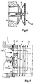
- ein weiteres im Bereich der Einlassöffnung des Bypass angeordnetes Bimetallelement, dem eine Prallplatte vorgeschaltet ist,
- Fig. 5
- eine Detailansicht eines Wärmetauschers mit einer Grundplatte, einer Zwischenplatte mit Bypass und einem Wärmetauschergehäuse.
- Die in Fig. 1 dargestellte Flüssigkeitsfilter-Wärmetauscher-Einheit 1 dient zum Kühlen und Reinigen von Motoröl oder Getriebeöl in einer Brennkraftmaschine und umfasst einen Flüssigkeitsfilter 2 und einen Wärmetauscher 3, wobei Flüssigkeitsfilter 2 und Wärmetauscher 3 zwar als eigenständige Bauteile ausgeführt sind, jedoch fest miteinander verbunden sind. Der Flüssigkeitsfilter 2 weist in einem Filtergehäuse 4 ein als Hohlzylinder ausgeführtes Filterelement 5 auf, dessen radiale Außenseite die von der zu reinigenden Rohflüssigkeit radial anzuströmende Rohseite 6 und dessen zylindrischer Innenraum die Reinseite 7 bildet, über die die gereinigte Flüssigkeit axial abgeführt wird. Das Filterelement 5 ist in einen Aufnahmeraum im Filtergehäuse 4 eingesetzt, wobei der zylindrische Innenraum des Filterelementes auf einen Gehäusestutzen 8 aufgesetzt ist, der Teil eines Ableitungsrohrs zur Ableitung der gereinigten Flüssigkeit in Pfeilrichtung 9 ist.
- Die Zufuhr der zu reinigenden, verschmutzten Flüssigkeit erfolgt in Pfeilrichtung 10 in einen im Filtergehäuse 4 ausgebildeten Zulaufkanal 11, in welchem ein Rücklaufsperrventil 12 zur Vermeidung eines unerwünschten Rückfließens der zu reinigenden Flüssigkeit entgegen Pfeilrichtung 10 angeordnet ist. Der Zulaufkanal 11 kommuniziert mit einer Einlassöffnung 13 im seitlich am Filtergehäuse 4 angeordneten Wärmetauscher 3. Im regulären Betrieb - oberhalb einer Schalt- bzw. Grenztemperatur der Flüssigkeit - strömt die zu reinigende Flüssigkeit durch den Zulaufkanal 11 und über die Einlassöffnung 13 in den Wärmetauscher 3, wird in diesem gekühlt und fließt anschließend über eine Auslassöffnung 14 im Gehäuse des Wärmetauschers 3 und einen Verbindungskanal 15 im Filtergehäuse in den äußeren, das Filterelement 5 umgreifenden Ringraum und trifft radial auf die Rohseite 6 des Filterelementes. Nach dem radialen Durchströmen des Filterelementes wird über die Reinseite 7 und den Gehäusestutzen 8 die gereinigte und gekühlte Flüssigkeit in Pfeilrichtung 9 abgeleitet.
- Der Zulaufkanal 11 ist über einen Bypass 16 in der Wandung des Filtergehäuses - welcher im Ausführungsbeispiel der Einlassöffnung 13 zum Wärmetauscher 3 gegenüberliegt - unmittelbar mit dem das Filterelement 5 umgreifenden Ringraum sowie der Rohseite 6 des Filterelementes verbunden. Die Bypassöffnung ist von einem im Bereich des Zulaufkanals 11 angeordneten Schaltglied 17 zu verschließen bzw. zu öffnen, wobei das Schaltglied 17 ein Bimetallelement 18 umfasst, welches bei Überschreiten und Unterschreiten einer spezifischen Schalttemperatur zwischen Schließposition und Öffnungsposition verstellt wird. In Fig. 1 ist das Schaltglied 17 in seiner Öffnungsposition dargestellt, in der der in den Zulaufkanal 11 einströmende Flüssigkeitsstrom (Teilstrom) unmittelbar über den Bypass 16 unter Umgehung des Wärmetauschers 3 zur Rohseite 6 des Filterelementes 5 geführt wird. Diese Position nimmt das Bimetallelement unterhalb seiner spezifischen Schalttemperatur ein, die im Falle einer Ölfilterung bzw. Ölkühlung beispielsweise bei 80° C liegt, um zu verhindern, dass die bei niedrigen Temperaturen erhöhte Viskosität der zu reinigenden Flüssigkeit zu einem erhöhten Anstieg des Druckes (Blockieren und Verstopfen) des Wärmetauschers 3 führt. Bei Überschreiten der Schalttemperatur wird das Bimetallelement 18 selbsttätig in seine zweite Schaltposition überführt, die der Schließposition entspricht und in der der Bypass 16 abgesperrt ist, so dass der gesamte Flüssigkeitsstrom über die Einlassöffnung 13 durch den Wärmetauscher 3 geführt wird.
- Am Boden des das Filterelement 5 aufnehmenden Aufnahmeraumes im Filtergehäuse 4 zweigt ein Ablaufkanal 20 ab, welcher von einer Schließfeder 19 zu verschließen ist, die bei eingesetztem Filterelement 5 von dessen Stirnseite axial in ihre Schließstellung beaufschlagt ist, in der der Ablaufkanal 20 verschlossen ist. Wird das Filterelement 5 dagegen aus dem Aufnahmeraum im Filtergehäuse 4 herausgenommen, wird die Schließfeder 19 auf Grund ihrer Eigenspannung selbsttätig in Öffnungsstellung versetzt und der Ablaufkanal 20 geöffnet. Daraufhin kann die gesamte, sich noch im Aufnahmeraum des Filtergehäuses 4 befindliche Flüssigkeit über den Ablaufkanal 20 abströmen. Da das Filterelement nur bei abgestellter Brennkraftmaschine entfernt wird und im Außerbetriebszustand der Brennkraftmaschine das Bimetallelement 18 durch Abkühlen der Flüssigkeit unterhalb der Schalttemperatur in seine Öffnungsposition versetzt wird, wird nach dem Abstellen der Brennkraftmaschine automatisch auch der nahezu gesamte Flüssigkeitsinhalt des Wärmetauschers 3 über den Bypass 16 und den Ablaufkanal 20 aus der Flüssigkeitsfilter-Wärmetauscher-Einheit 1 abgeleitet.
- Die Fig. 2 und 3 zeigen das Schaltglied 17 mit dem Bimetallelement 18 an der Öffnung des Bypass 16 in einer vergrößerten Darstellung. Gemäß Fig. 2 befindet sich das Bimetallelement 18 in seiner Öffnungsstellung, die Flüssigkeit kann in der dargestellten Pfeilrichtung durch den Bypass 16 strömen. Diese Position nimmt das Bimetallelement 18 unterhalb seiner Schalttemperatur ein.
- In Fig. 3 ist das Schaltglied 17 geschlossen, das Bimetallelement 18 verschließt die Öffnung des Bypass 16, so dass jeder Durchfluss durch den Bypass 16 verhindert wird. Diese Position nimmt das Bimetallelement 18 oberhalb seiner Schalttemperatur ein.
- In Fig. 4 ist dem Bimetallelement 18 des Schaltglieds 17 eine Prallplatte 21 vorgeschaltet, die beispielsweise als Kunststoffscheibe ausgeführt ist und verhindern soll, dass das Bimetallelement 18 in geöffneter Stellung (mit durchgezogenem Strich dargestellt) von dem Flüssigkeitsstrom mitgerissen und versehentlich in die mit gestricheltem Strich dargestellte Schließposition überführt wird. Die Prallplatte 21 kann gegebenenfalls auch die Funktion eines Befestigungselementes für das Bimetallelement 18 übernehmen. Der Durchmesser der Prallplatte 21 ist vorteilhaft so bemessen, dass das Bimetallelement 18 in geöffneter Stellung vollständig von der Prallplatte abgeschirmt wird.
- In der Ausführung gemäß Fig. 5 besteht der Wärmetauscher 3 aus einer Grund- bzw. Befestigungsplatte 22, auf die eine Zwischenplatte 23 aufgesetzt ist, die Träger des Wärmetauschergehäuses 24 ist. Der Bypass 16 ist in die Zwischenplatte 23 eingebracht, wobei das Bimetallelement 18 des Schaltglieds 17 im Bereich der Bypass-Einführöffnung angeordnet ist, die sich in der Grundplatte 22 befindet und mit dem Zulaufkanal für das Rohöl kommuniziert. Das Bimetallelement 18 ist an der Grundplatte 22 und somit auch am Wärmetauscher 3 gehalten.
- Über die Abströmöffnung des Bypass, die ebenfalls in die Grundplatte 22 eingebracht ist, ist der Bypass mit dem Verbindungskanal 15 zur Rohseite des Filterelements im Flüssigkeitsfilter 2 verbunden. Unterhalb der Schalttemperatur ist das Bimetallelement 18 geöffnet und zumindest ein Teil des Flüssigkeitsstromes kann unter Umgehung der Wärmetauscherelemente des Wärmetauschers 3 unmittelbar über den Bypass 16 in den Verbindungskanal 15 strömen. Oberhalb der Schalttemperatur ist das Bimetallelement 18 geschlossen, so dass der gesamte Flüssigkeitsstrom zur Kühlung durch den Wärmetauscher 3 und anschließend ebenfalls über den Verbindungskanal 15 zur Rohseite des Filterelements geleitet wird.
Claims (8)
- Flüssigkeitsfilter-Wärmetauscher-Einheit, insbesondere für Kraftfahrzeuge, wobei der Flüssigkeitsfilter (2) in einem Filtergehäuse (4) ein Filterelement (5) aufweist und die Rohseite (6) des Filterelements (5) mit dem Ablauf des Wärmetauschers (3) in Verbindung steht, mit einem Bypass (16), der unter Umgehung des Wärmetauschers (3) den Zulaufkanal (11) unmittelbar mit der Rohseite (6) des Filterelements (5) verbindet, wobei ein Schaltglied (17) zur Steuerung des Flüssigkeitsstromes in den Wärmetauscher (3) bzw. in den Bypass (16) vorgesehen ist,
dadurch gekennzeichnet,
dass das Schaltglied (17) ein Bimetallelement (18) umfasst, das unterhalb einer Schalttemperatur in einer den Flüssigkeitsstrom in den Bypass (16) leitenden Position steht. - Flüssigkeitsfilter-Wärmetauscher-Einheit nach Anspruch 1,
dadurch gekennzeichnet,
dass das Bimetallelement (18) an der Öffnung des Bypass (16) angeordnet ist. - Flüssigkeitsfilter-Wärmetauscher-Einheit nach Anspruch 1 oder 2,
dadurch gekennzeichnet,
dass das Bimetallelement (18) am Wärmetauscher (3) befestigt ist. - Flüssigkeitsfilter-Wärmetauscher-Einheit nach Anspruch 3,
dadurch gekennzeichnet,
dass das Bimetallelement (18) in einer Grundplatte (22) des Wärmetauschers (3) angeordnet ist. - Flüssigkeitsfilter-Wärmetauscher-Einheit nach einem der Ansprüche 1 bis 4,
dadurch gekennzeichnet,
dass der Zulaufkanal (11) sowohl mit dem Bypass (16) als auch mit der Einlassöffnung (13) des Wärmetauschers (3) kommuniziert. - Flüssigkeitsfilter-Wärmetauscher-Einheit nach einem der Ansprüche 1 bis 5,
dadurch gekennzeichnet,
dass der Zulaufkanal (11) im Filtergehäuse (4) ausgebildet ist. - Flüssigkeitsfilter-Wärmetauscher-Einheit nach einem der Ansprüche 1 bis 6,
dadurch gekennzeichnet,
dass dem Bimetallelement (18) eine Prallplatte (21) vorgelagert ist. - Verwendung der Flüssigkeitsfilter-Wärmetauscher-Einheit zur Ölfilterung und Ölkühlung in einem Kraftfahrzeug.
Applications Claiming Priority (2)
| Application Number | Priority Date | Filing Date | Title |
|---|---|---|---|
| DE10245005A DE10245005A1 (de) | 2002-09-26 | 2002-09-26 | Flüssigkeitsfilter-Wärmetauscher-Einheit |
| DE10245005 | 2002-09-26 |
Publications (2)
| Publication Number | Publication Date |
|---|---|
| EP1403475A1 true EP1403475A1 (de) | 2004-03-31 |
| EP1403475B1 EP1403475B1 (de) | 2007-12-12 |
Family
ID=31969628
Family Applications (1)
| Application Number | Title | Priority Date | Filing Date |
|---|---|---|---|
| EP03018810A Expired - Lifetime EP1403475B1 (de) | 2002-09-26 | 2003-08-19 | Flüssigkeitsfilter-Wärmetauscher-Einheit |
Country Status (4)
| Country | Link |
|---|---|
| US (1) | US6994784B2 (de) |
| EP (1) | EP1403475B1 (de) |
| AT (1) | ATE380926T1 (de) |
| DE (2) | DE10245005A1 (de) |
Cited By (5)
| Publication number | Priority date | Publication date | Assignee | Title |
|---|---|---|---|---|
| EP1782876A1 (de) * | 2005-11-02 | 2007-05-09 | Mahle International GmbH | Filter-Wärmeübertrager-Kombination für Flüssigkeiten, insbesondere Schmieröl eines Kraftfahrzeug-Verbrennungsmotors |
| EP1876406A1 (de) * | 2006-07-06 | 2008-01-09 | Behr GmbH & Co. KG | Wärmetauscher-Filter-Anordnung, insbesondere für ein Kraftfahrzeug |
| DE202007001227U1 (de) * | 2007-01-27 | 2008-08-28 | Hengst Gmbh & Co.Kg | Ölfilter mit Bypassbohrung zu einem Wärmetauscher |
| DE102009041525A1 (de) * | 2009-09-15 | 2011-03-24 | Mahle International Gmbh | Ölfiltermodul |
| EP3552681A1 (de) * | 2018-04-12 | 2019-10-16 | Hydac Fluidcarecenter GmbH | Filterelement für die ölfiltration |
Families Citing this family (35)
| Publication number | Priority date | Publication date | Assignee | Title |
|---|---|---|---|---|
| DE10245005A1 (de) * | 2002-09-26 | 2004-04-08 | Mann + Hummel Gmbh | Flüssigkeitsfilter-Wärmetauscher-Einheit |
| US7479219B2 (en) * | 2004-08-05 | 2009-01-20 | Guenther Rassinger | Filter device for fluids and method for filtering fluids |
| DE102005011221A1 (de) * | 2005-03-11 | 2006-09-14 | Mann+Hummel Gmbh | Flüssigkeitsfilter-Wärmetauscher-Einheit |
| DE102005012550A1 (de) * | 2005-03-18 | 2006-09-21 | Mahle International Gmbh | Filter-Kühler-Kombination für Flüssigkeiten, insbesondere Schmieröl eines Kraftfahrzeug-Verbrennungsmotors |
| DE202005010445U1 (de) * | 2005-06-30 | 2006-11-16 | Mann + Hummel Gmbh | Filteranordnung für Flüssigkeiten |
| DE102006034077A1 (de) * | 2005-08-16 | 2007-02-22 | Robert Bosch Gmbh | Filtereinrichtung mit einer Heizung |
| US8293103B2 (en) * | 2005-12-08 | 2012-10-23 | Donaldson Company, Inc. | Spin-on filter assembly and methods |
| BRPI0710570B1 (pt) * | 2006-04-21 | 2023-05-16 | Parker-Hannifin Corporation | Reservatório de fluxo cruzado integrado e elemento de filtro |
| US7625637B2 (en) * | 2006-05-31 | 2009-12-01 | Cabot Corporation | Production of metal nanoparticles from precursors having low reduction potentials |
| DE202006011339U1 (de) | 2006-07-20 | 2007-11-29 | Mann + Hummel Gmbh | Flüssigkeits-Wärmetauscher-Einheit |
| US7992667B2 (en) * | 2006-08-08 | 2011-08-09 | David Wayne Rennie | Oil cooling and filtering system, kit and apparatus |
| US20080128345A1 (en) * | 2006-11-30 | 2008-06-05 | Sotiriades Aleko D | Unified Oil Filter and Cooler |
| DE202007000746U1 (de) * | 2007-01-12 | 2008-05-21 | Mann+Hummel Gmbh | Kraftstofffilter |
| DE202007010956U1 (de) * | 2007-08-07 | 2008-12-18 | Mann+Hummel Gmbh | Kombinationsfilteranordnung |
| US7396473B1 (en) * | 2007-09-06 | 2008-07-08 | Guynn Stacy D | Engine oil filter |
| FR2928207B1 (fr) * | 2008-02-29 | 2010-03-26 | Hispano Suiza Sa | Installation d'echangeur thermique |
| DE202008014212U1 (de) | 2008-10-24 | 2010-04-01 | Mann+Hummel Gmbh | Wärmetauscher mit Umgehungsventil |
| US7997062B2 (en) * | 2009-01-29 | 2011-08-16 | Pratt & Whitney Canada Corp. | Dual channel regulated fuel-oil heat exchanger |
| DE102009016601B4 (de) | 2009-04-08 | 2025-07-17 | Mann+Hummel Gmbh | Filtereinrichtung für Fluide, insbesondere für Kraftstoffe |
| DE102010021990A1 (de) * | 2010-05-29 | 2011-12-01 | Mahle International Gmbh | Filter- und Kühlvorrichtung |
| DE102010034788A1 (de) * | 2010-08-18 | 2012-02-23 | Mann + Hummel Gmbh | Ölfiltermodul und Thermostateinheit |
| US8911620B2 (en) * | 2010-11-29 | 2014-12-16 | Vesa S. Silegren | Universal spin-on oil filter adapter |
| US9157399B2 (en) * | 2011-05-05 | 2015-10-13 | Hamilton Sundstrand Corporation | Fuel filter adapter |
| DE102012010718A1 (de) * | 2012-05-30 | 2013-12-05 | Robert Bosch Gmbh | Filtervorrichtung und Verfahren zurHerstellung einer Filtervorrichtung |
| US9890868B2 (en) * | 2013-09-20 | 2018-02-13 | General Electric Company | Aviation bypass valve including a shape memory alloy material |
| DE102015201932A1 (de) | 2015-02-04 | 2016-08-04 | Schaeffler Technologies AG & Co. KG | Vorrichtung zur Bremskraftregulierung an einem Elektrofahrrad |
| DE102015003101A1 (de) * | 2015-03-11 | 2016-09-15 | Mann + Hummel Gmbh | Filterelement |
| US10513020B2 (en) | 2015-09-21 | 2019-12-24 | Caterpillar Inc. | Hammer temperature protection system and method |
| CN107228037B (zh) * | 2016-03-23 | 2020-10-27 | 上海欧菲滤清器有限公司 | 燃油滤清器 |
| DE102016012935A1 (de) * | 2016-10-27 | 2018-05-03 | Mann + Hummel Gmbh | Filtersystem und Filterelement mit einem Rücklaufsperrelement |
| WO2021226187A1 (en) * | 2020-05-08 | 2021-11-11 | Cummins Inc. | Lubricant manifold for internal combustion engine |
| US12564801B2 (en) * | 2021-03-18 | 2026-03-03 | Volvo Truck Corporation | Oil filter with two filtrate outlets and vehicle lubrication circuit |
| EP4071344B1 (de) * | 2021-04-06 | 2024-04-24 | Hamilton Sundstrand Corporation | Filterventilanordnung |
| US12188468B2 (en) * | 2022-09-01 | 2025-01-07 | EKU Power Drives Inc. | Reservoir for dual loop lubrication and thermal management system for pumps |
| US11982234B1 (en) * | 2023-02-13 | 2024-05-14 | Pratt & Whitney Canada Corp. | Heat exchanger with bypass valve and thermal fuse |
Citations (4)
| Publication number | Priority date | Publication date | Assignee | Title |
|---|---|---|---|---|
| US2729339A (en) * | 1953-08-28 | 1956-01-03 | Purolator Products Inc | Automatic discriminatory clogging detector for oil filters |
| US4388196A (en) * | 1980-08-14 | 1983-06-14 | Claude A. Patalidis | Filter with heat controlled fluid flow bypass |
| DE19635777A1 (de) * | 1996-09-04 | 1998-03-05 | Mann & Hummel Filter | Baugruppe für eine Verbrennungskraftmaschine |
| DE10205518A1 (de) * | 2001-02-15 | 2002-09-26 | Mann & Hummel Filter | Thermostatgesteuertes Ventil |
Family Cites Families (14)
| Publication number | Priority date | Publication date | Assignee | Title |
|---|---|---|---|---|
| GB582260A (en) * | 1944-01-29 | 1946-11-11 | United Aircraft Corp | Improvements in or relating to temperature control for aircraft instruments |
| GB881764A (en) * | 1957-12-24 | 1961-11-08 | Renault | Improvements in or relating to the drive of fans for cooling radiators of vehicle engines |
| BE794794A (fr) * | 1971-11-04 | 1973-05-16 | Modine Mfg Cy | Appareil echangeur de chaleur |
| US4669532A (en) * | 1984-04-23 | 1987-06-02 | Kabushiki Kaisha Tsuchiya Seisakusho | Heat exchanger with temperature responsive bypass |
| JPS6144294A (ja) * | 1984-08-07 | 1986-03-03 | Nippon Denso Co Ltd | 熱交換器 |
| US4783271A (en) * | 1986-06-27 | 1988-11-08 | Pall Corporation | Temperature responsive bypass filter assembly |
| US5014775A (en) * | 1990-05-15 | 1991-05-14 | Toyo Radiator Co., Ltd. | Oil cooler and manufacturing method thereof |
| DE4113293A1 (de) * | 1991-04-24 | 1992-04-23 | Daimler Benz Ag | Temperaturabhaengig arbeitendes bypassventil |
| DE4128153C2 (de) * | 1991-08-24 | 1994-08-25 | Behr Gmbh & Co | Scheibenölkühler |
| US5406910A (en) * | 1993-11-22 | 1995-04-18 | Ford Motor Company | Combination oil cooler and oil filter assembly for internal combustion engine |
| CA2113519C (en) * | 1994-01-14 | 1999-06-08 | Allan K. So | Passive by-pass for heat exchangers |
| JP3186721B2 (ja) * | 1998-12-07 | 2001-07-11 | 三菱電機株式会社 | 溶接品質判定装置及びその装置を備えた溶接機 |
| DE10125120A1 (de) * | 2001-05-23 | 2002-11-28 | Daimler Chrysler Ag | Brennkraftmaschine mit einem Ölkreislauf |
| DE10245005A1 (de) * | 2002-09-26 | 2004-04-08 | Mann + Hummel Gmbh | Flüssigkeitsfilter-Wärmetauscher-Einheit |
-
2002
- 2002-09-26 DE DE10245005A patent/DE10245005A1/de not_active Withdrawn
-
2003
- 2003-08-19 DE DE50308772T patent/DE50308772D1/de not_active Expired - Lifetime
- 2003-08-19 AT AT03018810T patent/ATE380926T1/de not_active IP Right Cessation
- 2003-08-19 EP EP03018810A patent/EP1403475B1/de not_active Expired - Lifetime
- 2003-09-26 US US10/670,761 patent/US6994784B2/en not_active Expired - Fee Related
Patent Citations (4)
| Publication number | Priority date | Publication date | Assignee | Title |
|---|---|---|---|---|
| US2729339A (en) * | 1953-08-28 | 1956-01-03 | Purolator Products Inc | Automatic discriminatory clogging detector for oil filters |
| US4388196A (en) * | 1980-08-14 | 1983-06-14 | Claude A. Patalidis | Filter with heat controlled fluid flow bypass |
| DE19635777A1 (de) * | 1996-09-04 | 1998-03-05 | Mann & Hummel Filter | Baugruppe für eine Verbrennungskraftmaschine |
| DE10205518A1 (de) * | 2001-02-15 | 2002-09-26 | Mann & Hummel Filter | Thermostatgesteuertes Ventil |
Cited By (5)
| Publication number | Priority date | Publication date | Assignee | Title |
|---|---|---|---|---|
| EP1782876A1 (de) * | 2005-11-02 | 2007-05-09 | Mahle International GmbH | Filter-Wärmeübertrager-Kombination für Flüssigkeiten, insbesondere Schmieröl eines Kraftfahrzeug-Verbrennungsmotors |
| EP1876406A1 (de) * | 2006-07-06 | 2008-01-09 | Behr GmbH & Co. KG | Wärmetauscher-Filter-Anordnung, insbesondere für ein Kraftfahrzeug |
| DE202007001227U1 (de) * | 2007-01-27 | 2008-08-28 | Hengst Gmbh & Co.Kg | Ölfilter mit Bypassbohrung zu einem Wärmetauscher |
| DE102009041525A1 (de) * | 2009-09-15 | 2011-03-24 | Mahle International Gmbh | Ölfiltermodul |
| EP3552681A1 (de) * | 2018-04-12 | 2019-10-16 | Hydac Fluidcarecenter GmbH | Filterelement für die ölfiltration |
Also Published As
| Publication number | Publication date |
|---|---|
| DE50308772D1 (de) | 2008-01-24 |
| DE10245005A1 (de) | 2004-04-08 |
| US6994784B2 (en) | 2006-02-07 |
| EP1403475B1 (de) | 2007-12-12 |
| ATE380926T1 (de) | 2007-12-15 |
| US20040182566A1 (en) | 2004-09-23 |
Similar Documents
| Publication | Publication Date | Title |
|---|---|---|
| EP1403475B1 (de) | Flüssigkeitsfilter-Wärmetauscher-Einheit | |
| DE102009050696B4 (de) | Wärmetauscher-Einheit mit Umgehungsventil | |
| EP1307274B1 (de) | Flüssigkeitsfilter, insbesondere für schmieröl einer brennkraftmaschine | |
| DE60211323T2 (de) | Krafstofffilter mit umlaufventil | |
| EP3004620B1 (de) | Filterelement | |
| EP1137470B1 (de) | Fluidfilter mit gehäusefestem ablassdom | |
| EP1295025B1 (de) | Flüssigkeitskreislauf | |
| EP1198682B1 (de) | Schnellkupplung für das öffnen eines ventils | |
| DE202004018136U1 (de) | Öl-Kühlmittel-Modul | |
| EP1855778B1 (de) | Flüssigkeitsfilter-wärmetauscher-einheit | |
| DE29915844U1 (de) | Filter mit Ventil-Kombinationsbauteil | |
| EP1130224A1 (de) | Flüssigkeitsfilter mit einem Kühler | |
| DE2623621B1 (de) | Einrichtung zum beheizen der bedienungskabine einer maschine | |
| DE102012209703B3 (de) | Behälter für einen Hydraulikkreislauf | |
| WO2018146102A1 (de) | Fluidfilter mit einem filtereinsatz mit einem vor- und einem hauptfilterelement | |
| EP1350551B1 (de) | Ventilanordnung, insbesondere für den Schmierölkreislauf einer Brennkraftmaschine, beinhaltend ein Rücklaufsperrventil sowie ein Umgehungsventil | |
| EP2575999B1 (de) | Filter- und kühlvorrichtung | |
| DE19508650C2 (de) | Filteranordnung | |
| EP1220975B1 (de) | Fluidkühlvorrichtung | |
| EP1560636B1 (de) | Fluessigkeitsfilter, insbesondere oelfilter fuer kraftfahrzeuge | |
| EP2532848B1 (de) | Filter- und Kühlvorrichtung | |
| DE202004017745U1 (de) | Kühlmittel-Pflege-Einheit mit Rücklaufsperrventil | |
| DE102017001540B4 (de) | Filtervorrichtung, Filtervorrichtungsgehäuse und deren Verwendung | |
| EP1326695A2 (de) | Filtervorrichtung | |
| DE10302934A1 (de) | Filtergehäuse mit Wärmetauscheranordnung für einen Verbrennungsmotor |
Legal Events
| Date | Code | Title | Description |
|---|---|---|---|
| PUAI | Public reference made under article 153(3) epc to a published international application that has entered the european phase |
Free format text: ORIGINAL CODE: 0009012 |
|
| AK | Designated contracting states |
Kind code of ref document: A1 Designated state(s): AT BE BG CH CY CZ DE DK EE ES FI FR GB GR HU IE IT LI LU MC NL PT RO SE SI SK TR |
|
| AX | Request for extension of the european patent |
Extension state: AL LT LV MK |
|
| 17P | Request for examination filed |
Effective date: 20040423 |
|
| AKX | Designation fees paid |
Designated state(s): AT BE BG CH CY CZ DE DK EE ES FI FR GB GR HU IE IT LI LU MC NL PT RO SE SI SK TR |
|
| 17Q | First examination report despatched |
Effective date: 20070111 |
|
| GRAP | Despatch of communication of intention to grant a patent |
Free format text: ORIGINAL CODE: EPIDOSNIGR1 |
|
| GRAS | Grant fee paid |
Free format text: ORIGINAL CODE: EPIDOSNIGR3 |
|
| GRAA | (expected) grant |
Free format text: ORIGINAL CODE: 0009210 |
|
| AK | Designated contracting states |
Kind code of ref document: B1 Designated state(s): AT BE BG CH CY CZ DE DK EE ES FI FR GB GR HU IE IT LI LU MC NL PT RO SE SI SK TR |
|
| REG | Reference to a national code |
Ref country code: GB Ref legal event code: FG4D Free format text: NOT ENGLISH |
|
| REG | Reference to a national code |
Ref country code: CH Ref legal event code: EP |
|
| REG | Reference to a national code |
Ref country code: IE Ref legal event code: FG4D Free format text: LANGUAGE OF EP DOCUMENT: GERMAN |
|
| REF | Corresponds to: |
Ref document number: 50308772 Country of ref document: DE Date of ref document: 20080124 Kind code of ref document: P |
|
| PG25 | Lapsed in a contracting state [announced via postgrant information from national office to epo] |
Ref country code: SE Free format text: LAPSE BECAUSE OF FAILURE TO SUBMIT A TRANSLATION OF THE DESCRIPTION OR TO PAY THE FEE WITHIN THE PRESCRIBED TIME-LIMIT Effective date: 20080312 |
|
| PG25 | Lapsed in a contracting state [announced via postgrant information from national office to epo] |
Ref country code: SI Free format text: LAPSE BECAUSE OF FAILURE TO SUBMIT A TRANSLATION OF THE DESCRIPTION OR TO PAY THE FEE WITHIN THE PRESCRIBED TIME-LIMIT Effective date: 20071212 Ref country code: NL Free format text: LAPSE BECAUSE OF FAILURE TO SUBMIT A TRANSLATION OF THE DESCRIPTION OR TO PAY THE FEE WITHIN THE PRESCRIBED TIME-LIMIT Effective date: 20071212 Ref country code: FI Free format text: LAPSE BECAUSE OF FAILURE TO SUBMIT A TRANSLATION OF THE DESCRIPTION OR TO PAY THE FEE WITHIN THE PRESCRIBED TIME-LIMIT Effective date: 20071212 |
|
| NLV1 | Nl: lapsed or annulled due to failure to fulfill the requirements of art. 29p and 29m of the patents act | ||
| GBV | Gb: ep patent (uk) treated as always having been void in accordance with gb section 77(7)/1977 [no translation filed] | ||
| PG25 | Lapsed in a contracting state [announced via postgrant information from national office to epo] |
Ref country code: CZ Free format text: LAPSE BECAUSE OF FAILURE TO SUBMIT A TRANSLATION OF THE DESCRIPTION OR TO PAY THE FEE WITHIN THE PRESCRIBED TIME-LIMIT Effective date: 20071212 Ref country code: ES Free format text: LAPSE BECAUSE OF FAILURE TO SUBMIT A TRANSLATION OF THE DESCRIPTION OR TO PAY THE FEE WITHIN THE PRESCRIBED TIME-LIMIT Effective date: 20080323 |
|
| PG25 | Lapsed in a contracting state [announced via postgrant information from national office to epo] |
Ref country code: RO Free format text: LAPSE BECAUSE OF FAILURE TO SUBMIT A TRANSLATION OF THE DESCRIPTION OR TO PAY THE FEE WITHIN THE PRESCRIBED TIME-LIMIT Effective date: 20071212 Ref country code: SK Free format text: LAPSE BECAUSE OF FAILURE TO SUBMIT A TRANSLATION OF THE DESCRIPTION OR TO PAY THE FEE WITHIN THE PRESCRIBED TIME-LIMIT Effective date: 20071212 |
|
| EN | Fr: translation not filed | ||
| PG25 | Lapsed in a contracting state [announced via postgrant information from national office to epo] |
Ref country code: PT Free format text: LAPSE BECAUSE OF FAILURE TO SUBMIT A TRANSLATION OF THE DESCRIPTION OR TO PAY THE FEE WITHIN THE PRESCRIBED TIME-LIMIT Effective date: 20080512 |
|
| REG | Reference to a national code |
Ref country code: IE Ref legal event code: FD4D |
|
| PLBE | No opposition filed within time limit |
Free format text: ORIGINAL CODE: 0009261 |
|
| STAA | Information on the status of an ep patent application or granted ep patent |
Free format text: STATUS: NO OPPOSITION FILED WITHIN TIME LIMIT |
|
| PG25 | Lapsed in a contracting state [announced via postgrant information from national office to epo] |
Ref country code: FR Free format text: LAPSE BECAUSE OF FAILURE TO SUBMIT A TRANSLATION OF THE DESCRIPTION OR TO PAY THE FEE WITHIN THE PRESCRIBED TIME-LIMIT Effective date: 20080926 Ref country code: IE Free format text: LAPSE BECAUSE OF FAILURE TO SUBMIT A TRANSLATION OF THE DESCRIPTION OR TO PAY THE FEE WITHIN THE PRESCRIBED TIME-LIMIT Effective date: 20071212 Ref country code: DK Free format text: LAPSE BECAUSE OF FAILURE TO SUBMIT A TRANSLATION OF THE DESCRIPTION OR TO PAY THE FEE WITHIN THE PRESCRIBED TIME-LIMIT Effective date: 20071212 |
|
| 26N | No opposition filed |
Effective date: 20080915 |
|
| PG25 | Lapsed in a contracting state [announced via postgrant information from national office to epo] |
Ref country code: GB Free format text: LAPSE BECAUSE OF FAILURE TO SUBMIT A TRANSLATION OF THE DESCRIPTION OR TO PAY THE FEE WITHIN THE PRESCRIBED TIME-LIMIT Effective date: 20071212 |
|
| PG25 | Lapsed in a contracting state [announced via postgrant information from national office to epo] |
Ref country code: GR Free format text: LAPSE BECAUSE OF FAILURE TO SUBMIT A TRANSLATION OF THE DESCRIPTION OR TO PAY THE FEE WITHIN THE PRESCRIBED TIME-LIMIT Effective date: 20080313 |
|
| PG25 | Lapsed in a contracting state [announced via postgrant information from national office to epo] |
Ref country code: MC Free format text: LAPSE BECAUSE OF NON-PAYMENT OF DUE FEES Effective date: 20080831 |
|
| REG | Reference to a national code |
Ref country code: CH Ref legal event code: PL |
|
| PG25 | Lapsed in a contracting state [announced via postgrant information from national office to epo] |
Ref country code: EE Free format text: LAPSE BECAUSE OF FAILURE TO SUBMIT A TRANSLATION OF THE DESCRIPTION OR TO PAY THE FEE WITHIN THE PRESCRIBED TIME-LIMIT Effective date: 20071212 Ref country code: BG Free format text: LAPSE BECAUSE OF FAILURE TO SUBMIT A TRANSLATION OF THE DESCRIPTION OR TO PAY THE FEE WITHIN THE PRESCRIBED TIME-LIMIT Effective date: 20080312 |
|
| PG25 | Lapsed in a contracting state [announced via postgrant information from national office to epo] |
Ref country code: LI Free format text: LAPSE BECAUSE OF NON-PAYMENT OF DUE FEES Effective date: 20080831 Ref country code: CH Free format text: LAPSE BECAUSE OF NON-PAYMENT OF DUE FEES Effective date: 20080831 |
|
| PG25 | Lapsed in a contracting state [announced via postgrant information from national office to epo] |
Ref country code: BE Free format text: LAPSE BECAUSE OF NON-PAYMENT OF DUE FEES Effective date: 20080831 Ref country code: CY Free format text: LAPSE BECAUSE OF FAILURE TO SUBMIT A TRANSLATION OF THE DESCRIPTION OR TO PAY THE FEE WITHIN THE PRESCRIBED TIME-LIMIT Effective date: 20071212 |
|
| PG25 | Lapsed in a contracting state [announced via postgrant information from national office to epo] |
Ref country code: AT Free format text: LAPSE BECAUSE OF NON-PAYMENT OF DUE FEES Effective date: 20080819 |
|
| PG25 | Lapsed in a contracting state [announced via postgrant information from national office to epo] |
Ref country code: HU Free format text: LAPSE BECAUSE OF FAILURE TO SUBMIT A TRANSLATION OF THE DESCRIPTION OR TO PAY THE FEE WITHIN THE PRESCRIBED TIME-LIMIT Effective date: 20080613 Ref country code: LU Free format text: LAPSE BECAUSE OF NON-PAYMENT OF DUE FEES Effective date: 20080819 |
|
| PG25 | Lapsed in a contracting state [announced via postgrant information from national office to epo] |
Ref country code: TR Free format text: LAPSE BECAUSE OF FAILURE TO SUBMIT A TRANSLATION OF THE DESCRIPTION OR TO PAY THE FEE WITHIN THE PRESCRIBED TIME-LIMIT Effective date: 20071212 |
|
| PG25 | Lapsed in a contracting state [announced via postgrant information from national office to epo] |
Ref country code: IT Free format text: LAPSE BECAUSE OF NON-PAYMENT OF DUE FEES Effective date: 20080831 |
|
| PGFP | Annual fee paid to national office [announced via postgrant information from national office to epo] |
Ref country code: DE Payment date: 20150821 Year of fee payment: 13 |
|
| REG | Reference to a national code |
Ref country code: DE Ref legal event code: R119 Ref document number: 50308772 Country of ref document: DE |
|
| PG25 | Lapsed in a contracting state [announced via postgrant information from national office to epo] |
Ref country code: DE Free format text: LAPSE BECAUSE OF NON-PAYMENT OF DUE FEES Effective date: 20170301 |