EP1560636B1 - Fluessigkeitsfilter, insbesondere oelfilter fuer kraftfahrzeuge - Google Patents
Fluessigkeitsfilter, insbesondere oelfilter fuer kraftfahrzeuge Download PDFInfo
- Publication number
- EP1560636B1 EP1560636B1 EP03784014A EP03784014A EP1560636B1 EP 1560636 B1 EP1560636 B1 EP 1560636B1 EP 03784014 A EP03784014 A EP 03784014A EP 03784014 A EP03784014 A EP 03784014A EP 1560636 B1 EP1560636 B1 EP 1560636B1
- Authority
- EP
- European Patent Office
- Prior art keywords
- filter
- filter element
- liquid
- locking device
- housing
- Prior art date
- Legal status (The legal status is an assumption and is not a legal conclusion. Google has not performed a legal analysis and makes no representation as to the accuracy of the status listed.)
- Expired - Lifetime
Links
- 239000007788 liquid Substances 0.000 title claims description 15
- 238000007789 sealing Methods 0.000 claims description 10
- 238000006073 displacement reaction Methods 0.000 claims 1
- 239000003921 oil Substances 0.000 description 18
- 238000004140 cleaning Methods 0.000 description 2
- 238000003780 insertion Methods 0.000 description 2
- 230000037431 insertion Effects 0.000 description 2
- 238000009434 installation Methods 0.000 description 2
- 238000012423 maintenance Methods 0.000 description 2
- 230000005540 biological transmission Effects 0.000 description 1
- 238000011109 contamination Methods 0.000 description 1
- 230000001419 dependent effect Effects 0.000 description 1
- 238000011161 development Methods 0.000 description 1
- 230000018109 developmental process Effects 0.000 description 1
- 239000012530 fluid Substances 0.000 description 1
- 239000010687 lubricating oil Substances 0.000 description 1
- 239000002184 metal Substances 0.000 description 1
- 238000012546 transfer Methods 0.000 description 1
Images

Classifications
-
- B—PERFORMING OPERATIONS; TRANSPORTING
- B01—PHYSICAL OR CHEMICAL PROCESSES OR APPARATUS IN GENERAL
- B01D—SEPARATION
- B01D35/00—Filtering devices having features not specifically covered by groups B01D24/00 - B01D33/00, or for applications not specifically covered by groups B01D24/00 - B01D33/00; Auxiliary devices for filtration; Filter housing constructions
- B01D35/14—Safety devices specially adapted for filtration; Devices for indicating clogging
- B01D35/147—Bypass or safety valves
-
- B—PERFORMING OPERATIONS; TRANSPORTING
- B01—PHYSICAL OR CHEMICAL PROCESSES OR APPARATUS IN GENERAL
- B01D—SEPARATION
- B01D35/00—Filtering devices having features not specifically covered by groups B01D24/00 - B01D33/00, or for applications not specifically covered by groups B01D24/00 - B01D33/00; Auxiliary devices for filtration; Filter housing constructions
- B01D35/14—Safety devices specially adapted for filtration; Devices for indicating clogging
- B01D35/153—Anti-leakage or anti-return valves
-
- B—PERFORMING OPERATIONS; TRANSPORTING
- B01—PHYSICAL OR CHEMICAL PROCESSES OR APPARATUS IN GENERAL
- B01D—SEPARATION
- B01D35/00—Filtering devices having features not specifically covered by groups B01D24/00 - B01D33/00, or for applications not specifically covered by groups B01D24/00 - B01D33/00; Auxiliary devices for filtration; Filter housing constructions
- B01D35/16—Cleaning-out devices, e.g. for removing the cake from the filter casing or for evacuating the last remnants of liquid
Definitions
- the invention relates to a fluid filter, in particular to an oil filter for motor vehicles, according to the preamble of claim 1.
- a filter system in which a replaceable filter is arranged in a housing. This replaceable filter is attached to a central tube.
- a valve is arranged in the bottom region, which is actuated by the filter element and opens or closes a liquid drain. This valve consists of several complex components.
- a filter system which also shows a filter element in a housing.
- the filter element has a pin which cooperates with a valve disposed in the housing and also provides there for a floor drain.
- a valve disposed in the housing and also provides there for a floor drain.
- a filter housing which in turn has a drain valve, which is actuated by a filter element.
- a drain valve which is actuated by a filter element.
- the print font EP 1 159 998 A2 open beard a ring-shaped formed spring clip for closing the drain opening fietergephaseuses.
- the spring clip over the support body opening of the housing floor is inserted, actuated
- the invention is based on the problem of developing a liquid filter in such a way that with simple measures in the filter housing remaining liquid can be drained.
- the filter element in the filter housing acts on a closure part which, in a closed position, obstructs a discharge opening in the filter housing and releases the discharge opening in the opening position.
- the movement of the filter element during its insertion or removal from the filter housing is used as an adjusting movement for the transfer of the closure part between its opening and closing position.
- the closure element is automatically closed when inserting the filter element in its operating position in the filter housing, so that the filter can exercise its regular cleaning function again.
- the closure part is a spring clip.
- the spring clip is annular and has a central recess which is seated in the installed position of the spring clip in the filter housing on a discharge nozzle, through which the cleaned liquid is discharged after passing through the filter element in the regular filter operation of the filter housing.
- the closure part is subjected to a force in the direction of its opening position, so that the closure part is automatically moved into the open position upon removal of the filter element due to the forces acting on it and the outlet opening is opened.
- the closure member is adjusted against the opening force in the closed position.
- the opening and closing movement of the closure part is directly coupled to the movement of the filter element.
- this embodiment can be dispensed with a force application of the closure part.
- a spring clip is used, to which a sealing plug is attached for closing the discharge opening.
- the spring clip is under a residual stress, the force applied to the clip in its open position.
- the spring clip is deformed against its internal stress and acted upon in the closed position, whereupon the sealing plug is placed on the drain opening and this locks.
- the spring clip which advantageously consists of a thin-walled sheet, be curved three-dimensionally, the region of the Dichtpfropfens, which is seated in the closed position on the ground, set back, a middle region, however, is increased, since in this central region the spring clip is expediently pressed by the filter element in its closed position. In this way, a closure element with a sufficient residual stress can be produced by simple means.
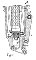
- the in Fig. 1 shown oil filter 1 is used in particular in motor vehicles, for example, for cleaning transmission oil or lubricating oil, which is to supply various bearings on the engine block.
- the oil filter 1 comprises a filter housing 2, in which a filter element 4 is accommodated and which is to be closed by a housing cover 3.
- the filter element 4 is designed annular or hollow cylindrical and is flowed to clean the oil radially from outside to inside. The clean side is therefore in the central interior of the filter element, from which the cleaned oil axially over a Outflow 5 is derived.
- Centrally located in the interior of the filter element 4 is a support tube 6, which gives the filter element additional stability and in particular is inserted into the filter element.
- a discharge opening 7 which opens into a discharge channel 8, on the removal of the filter element 4 from the oil filter, for example, for maintenance, the remaining in the filter housing Residual oil can be derived and, for example, can be performed in an oil pan of the engine.
- the drain opening 7 is located in particular at an inclined mounting position of the filter at the lowest point of the filter housing interior, in order to derive the largest possible amount of residual oil.
- the discharge opening 7 is to be closed by a sealing plug 11, which is arranged on a closure part 9 designed as a spring clip, which is designed approximately annular and is placed around the central outlet nozzle 5 at the bottom in the filter housing.
- the spring clip 9 consists of a thin-walled sheet, which is elastically deformable.
- the spring clip 9 is connected on its side opposite the drain opening 7 side via a mounting geometry, in particular a fastening screw 10 fixed to the filter housing 2.
- the spring clasp 9 is formed three-dimensionally, wherein in the installed position, a central portion between the attachment point to the fastening screw 10 and the opposite sealing plug 11 is formed increased, the attachment point and the sealing plug 11-bearing portion are, however, reset down and both are at the same height. Due to the residual stress, the spring clip 9 is in the open position in the event that no external forces act on it.
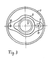
- the top view according Fig. 3 It can be seen that fastening screw 10 and sealing plug 11 are arranged on opposite sides in the annular housing bottom of the set around the outlet nozzle 5 closure part 9.
- the closure member 9 is annular and consists of a thin-walled sheet metal, wherein the Blecharme of the closure part, which connect the portion with the fastening screw 10 and the portion with the sealing plug 11, are narrow, whereby a relatively high elasticity in the closure part 9 is formed.
Landscapes
- Chemical & Material Sciences (AREA)
- Chemical Kinetics & Catalysis (AREA)
- Lubrication Details And Ventilation Of Internal Combustion Engines (AREA)
- Filtration Of Liquid (AREA)
Description
- Die Erfindung bezieht sich auf einen Flüssigkeitsfilter, insbesondere auf einen Ölfilter für Kraftfahrzeuge, nach dem Oberbegriff des Anspruches 1.
- Aus der
DE 199 34 378 ist ein Filtersystem bekannt, bei dem ein Wechselfilter in einem Gehäuse angeordnet ist. Dieser Wechselfilter ist an einem Mittelrohr befestigt. Im Gehäuse ist im Bodenbereich ein Ventil angeordnet, das vom Filterelement betätigt wird und einen Flüssigkeitsablauf öffnet oder verschließt. Dieses Ventil besteht aus mehreren komplexen Komponenten. - Es ist weiterhin aus der
WO02/36940 - Aus der
US 5,922,196 ist ein Filtergehäuse bekannt, welches wiederum ein Ablaufventil aufweist, das von einem Filterelement betätigt wird. Auch hier handelt es sich um mehrere Bauteile, die das Ablaufventil bilden und einen relativ hohen Montageaufwand erfordern. - In der Druckschrift
DE 197 46 752 A1 wird ein Ölfilter mit einem ringförmigen Filtereinsatz beschrieben, welcher in einem Filtergehäuse aufgenommen ist, das üblicherweise von einem Gehäusedeckel zu verschließen ist. Um für Wartungsarbeiten den Filtereinsatz austauschen zu können, wird der Deckel abgeschraubt, wobei darauf geachtet werden muss, dass in dem Filtergehäuse verbliebenes Restöl nicht versehentlich ausläuft und zu Verschmutzungen führt. Dieses Problem stellt sich insbesondere bei Ölfiltern, die in Schräglage eingebaut werden. - Die Druck schrift
EP 1 159 998 A2 offen bart eine ring förmig aus gebildete feder spange zum Verschließen der Ablass öffnungades fietergehäuses. Bei dieser Druchschrift wird die Feder spange über den Stütz Körper öffnung des gehäuse bodens einsteckbar ist, betätigte - Um vor dem Öffnen des Deckels das im Filtergehäuse befindliche Öl ablassen zu können, sind Ölfilterausführungen mit einer Ablassschraube bekannt, die manuell zu öffnen ist und über die das verbliebene Öl aus dem Filtergehäuse abgelassen werden kann. Die manuelle Betätigung der Ablassschraube ist jedoch verhältnismäßig mühsam und aufwendig, zudem setzt dies entsprechende Einbauverhältnisse voraus, die einen Zugang zur Ablassschraube ermöglichen.
- Der Erfindung liegt das Problem zugrunde, einen Flüssigkeitsfilter in der Weise weiterzubilden, dass mit einfachen Maßnahmen im Filtergehäuse verbliebene Flüssigkeit abgelassen werden kann.
- Dieses Problem wird erfindungsgemäß mit den Merkmalen des Anspruches 1 gelöst. Die Unteransprüche geben zweckmäßige Weiterbildungen an.
- Bei dem erfindungsgemäßen Flüssigkeitsfilter beaufschlagt das Filterelement im Filtergehäuse ein Verschlussteil, welches in einer Schließposition eine Ablassöffnung im Filtergehäuse versperrt und in Öffnungsposition die Ablassöffnung freigibt. Die Bewegung des Filterelementes bei dessen Einsetzen bzw. Entfernen aus dem Filtergehäuse wird als Stellbewegung für die Überführung des Verschlussteiles zwischen dessen Öffnungs- und Schließposition herangezogen. Auf diese Weise ist ein selbsttätiges Öffnen und Schließen der Ablassöffnung und dementsprechend ein automatisches Ablassen der verbliebenen Flüssigkeit im Filtergehäuse möglich. Weitere, insbesondere manuelle Eingriffe zum Ablassen der Flüssigkeit sind nicht erforderlich. Das Ablassen erfolgt automatisch beim Entfernen des Filterelementes aus seiner Betriebsposition im Filtergehäuse. Umgekehrt wird das Verschlusselement beim Einsetzen des Filterelementes in seine Betriebsposition im Filtergehäuse automatisch geschlossen, so dass der Filter wieder seine reguläre Reinigungsfunktion ausüben kann. Das Verschlussteil ist eine Federspange. Die Federspange ist ringförmig ausgebildet und weist eine zentrale Ausnehmung auf, die in Einbaulage der Federspange im Filtergehäuse auf einem Ablaufstutzen aufsitzt, über den die gereinigte Flüssigkeit nach Passieren des Filterelementes im regulären Filterbetrieb aus dem Filtergehäuse abgeleitet wird.
- In einer zweckmäßigen Ausführung ist das Verschlussteil in Richtung seiner Öffnungsposition kraftbeaufschlagt, so dass das Verschlussteil bei einem Entfernen des Filterelementes selbsttätig auf Grund der einwirkenden Kräfte in die Öffnungsposition verstellt und die Ablassöffnung geöffnet wird. Beim Einsetzen des Filterelementes wird das Verschlussteil gegen die Öffnungskraft in die Schließposition verstellt.
- Gemäß einer alternativen, zweckmäßigen Ausführung kann es aber auch angezeigt sein, dass die Öffnungs- und Schließbewegung des Verschlussteiles unmittelbar mit der Bewegung des Filterelementes gekoppelt ist. In dieser Ausführung kann auf eine Kraftbeaufschlagung des Verschlussteiles verzichtet werden.
- Als Verschlussteil wird - wie bereits erwähnt - eine Federspange verwendet, an der ein Dichtpfropfen zum Verschließen der Ablassöffnung befestigt ist. Die Federspange steht unter einer Eigenspannung, die die Spange in ihre Öffnungsposition kraftbeaufschlagt. Beim Einsetzen des Filterelementes wird die Federspange gegen ihre Eigenspannung verformt und in Schließposition beaufschlagt, woraufhin der Dichtpfropfen auf die Ablassöffnung aufgesetzt wird und diese versperrt.
- Zur Erzeugung der Eigenspannung kann die Federspange, die vorteilhaft aus einem dünnwandigen Blech besteht, dreidimensional gewölbt sein, wobei der Bereich des Dichtpfropfens, der in Schließposition auf dem Boden aufsitzt, zurückversetzt ist, ein mittlerer Bereich dagegen erhöht ausgebildet ist, da in diesem mittleren Bereich die Federspange zweckmäßig von dem Filterelement in ihre Schließposition gedrückt wird. Auf diese Weise kann mit einfachen Mitteln ein Verschlusselement mit einer ausreichenden Eigenspannung hergestellt werden.
- Weitere Vorteile und zweckmäßige Ausführungen sind den weiteren Ansprüchen, der Figurenbeschreibung und den Zeichnungen zu entnehmen. Es zeigen:
- Fig. 1
- einen Schnitt durch einen Ölfilter für Kraftfahrzeuge, mit einem hohlzylindrischen Filterelement in einem Filtergehäuse, welches von einem Gehäusedeckel zu verschließen ist, wobei der Gehäusedeckel teilweise angehoben und das Filterelement ebenfalls teilweise aus seiner regulären Betriebsposition im Filtergehäuse herausgehoben ist,
- Fig. 2
- der Ölfilter gemäß
Fig. 1 , jedoch mit dem Filterelement in seiner vollständig in das Filtergehäuse eingeführten, regulären Betriebsposition, in welcher eine Ablassöffnung am Boden des Filtergehäuses verschlossen ist, - Fig. 3
- eine Ansicht von oben in das Filtergehäuse bei entferntem Filterelement.
- In den Figuren sind gleiche Bauteile mit gleichen Bezugszeichen versehen.
- Der in
Fig. 1 dargestellte Ölfilter 1 wird insbesondere in Kraftfahrzeugen eingesetzt, beispielsweise zur Reinigung von Getriebeöl oder von Schmieröl, welches diversen Lagerstellen am Motorblock zuzuführen ist. Der Ölfilter 1 umfasst ein Filtergehäuse 2, in welchem ein Filterelement 4 aufgenommen ist und das von einem Gehäusedeckel 3 zu verschließen ist. Das Filterelement 4 ist ringförmig bzw. hohlzylindrisch ausgeführt und wird zur Reinigung des Öls radial von außen nach innen angeströmt. Die Reinseite befindet sich demnach im zentrischen Innenraum des Filterelementes, aus dem das gereinigte Öl axial über einen Ablaufstutzen 5 abgeleitet wird. Zentrisch im Inneren des Filterelementes 4 befindet sich ein Trägerrohr 6, welches dem Filterelement zusätzliche Stabilität verleiht und insbesondere in das Filterelement eingeschoben wird. - Am ringförmigen Boden im Filtergehäuse, auf dem das Filterelement 6 in seiner Betriebsposition stirnseitig aufsitzt, befindet sich eine Ablassöffnung 7, die in einen Ablasskanal 8 mündet, über den bei einem Entfernen des Filterelementes 4 aus dem Ölfilter, beispielsweise für Wartungszwecke, das im Filtergehäuse verbliebene Restöl abgeleitet werden kann und beispielsweise in eine Ölwanne der Brennkraftmaschine geführt werden kann. Die Ablassöffnung 7 befindet sich insbesondere bei einer geneigten Einbaulage des Filters am tiefsten Punkt des Filtergehäuse-Innenraumes, um die größtmögliche Menge Restöls ableiten zu können. Die Ablassöffnung 7 ist von einem Dichtpfropfen 11 zu verschließen, welcher an einem als Federspange ausgeführten Verschlussteil 9 angeordnet ist, welches etwa ringförmig ausgeführt ist und um den zentralen Ablaufstutzen 5 am Boden im Filtergehäuse gelegt ist. Die Federspange 9 besteht aus einem dünnwandigen Blech, welches elastisch verformbar ist. Die Federspange 9 ist auf ihrer der Ablassöffnung 7 gegenüberliegenden Seite über eine Befestigungsgeometrie, insbesondere eine Befestigungsschraube 10 fest mit dem Filtergehäuse 2 verbunden. Die Federspange 9 ist dreidimensional geformt, wobei in Einbaulage ein mittlerer Abschnitt zwischen dem Befestigungspunkt an der Befestigungsschraube 10 und dem gegenüberliegenden Dichtpfropfen 11 erhöht ausgebildet ist, der Befestigungspunkt und der den Dichtpfropfen 11 tragende Abschnitt dagegen nach unten zurückgesetzt sind und beide auf gleicher Höhe liegen. Auf Grund der Eigenspannung befindet sich die Federspange 9 für den Fall, dass keine äußeren Kräfte auf sie einwirken, in ihrer Öffnungsstellung. Durch eine Beaufschlagung in Achsrichtung, hervorgerufen durch das Einführen des Filterelementes 4 in seine Betriebsstellung, in welcher die axiale Stirnseite des Filterelementes auf die elastisch verformbare Federspange 9 einwirkt, wird diese in ihre Schließposition verstellt, in welcher der Dichtpfropfen 11 flüssigkeitsdicht auf der Ablassöffnung 7 aufsitzt. Diese Verhältnisse sind in
Fig. 2 dargestellt. Die Federspange 9 wird hierbei vorteilhaft von einem Vliesring 12 beaufschlagt, der sich an der axialen Stirnseite des Filterelementes 4 befindet und Bestandteil des Filterelementes ist. Auf Grund der Eigenelastizität der Federspange 9 wird diese wieder selbsttätig in ihre Öffnungsstellung überführt, sobald das Filterelement 4 axial aus seiner Betriebsstellung herausgehoben und aus dem Filtergehäuse entfernt wird. - Gemäß einer alternativen Ausführung kann es auch zweckmäßig sein, sowohl die Öffnungsbewegung als auch die Schließbewegung des Verschlussteiles an die axiale Stellbewegung des Filterelement bzw. des zentrisch angeordneten Trägerrohrs zu koppeln und über diese Stellbewegung zu steuern.
- Der Draufsicht gemäß
Fig. 3 ist zu entnehmen, dass Befestigungsschraube 10 und Dichtpfropfen 11 auf gegenüberliegenden Seiten in dem ringförmigen Gehäuseboden des um den Ablaufstutzen 5 gelegten Verschlussteiles 9 angeordnet sind. Das Verschlussteil 9 ist ringförmig gestaltet und besteht aus einem dünnwandigen Blech, wobei die Blecharme des Verschlussteiles, welche den Abschnitt mit der Befestigungsschraube 10 und den Abschnitt mit dem Dichtpfropfen 11 verbinden, schmal ausgebildet sind, wodurch eine relativ hohe Elastizität im Verschlussteil 9 gebildet ist.
Claims (6)
- Flüssigkeitsfilter, insbesondere Ölfilter für Kraftfahrzeuge, mit einem in einem Filtergehäuse (2) aufgenommenen Filterelement (4), dessen Rohseite von der zu reinigenden Flüssigkeit angeströmt wird, wobei im Filtergehäuse (2) eine Ablassöffnung (7) angeordnet ist, die über ein zwischen Öffnungs- und Schließposition zu verstellendes Verschlussteil (9) zu öffnen bzw. zu verschließen ist, wobei das Verschlussteil eine Felderspange ist, an der ein Dichtpfropfen zum Verschließen der Ablassöffnung befestigt ist,
dadurch gekennzeichnet,
dass die Federspange (9) ringförmig ausgebildet ist und eine zentrale Ausnehmung aufweist, die einen Ablaufstutzen (5) im Filtergehäuse (2) umschließt und dass eine axiale Stirnseite des Filterelements (4) das Verschlussteil (9) beaufschlagt. - Flüssigkeitsfilter nach Anspruch 1,
dadurch gekennzeichnet,
dass das Verschlussteil (9) in seine Öffnungsposition kraftbeaufschlagt ist und von dem in das Filtergehäuse (2) eingesetzten Filterelement (4) in die Schließposition gedrückt wird. - Flüssigkeitsfilter nach Anspruch 2 und 3,
dadurch gekennzeichnet,
dass die Federspange (9) unter Eigenspannung steht, die die Federspange (9) in ihre Öffnungsposition kraftbeaufschlagt. - Flüssigkeitsfilter nach einem der vorherigen Ansprüche,
dadurch gekennzeichnet,
dass die Federspange (9) im Bereich des Dichtpfropfens (11) zurückversetzt ist und in einem mittleren, von dem Filterelement (4) beaufschlagten Bereich erhöht ausgebildet ist. - Flüssigkeitsfilter nach Anspruch 4,
dadurch gekennzeichnete
dass die Stirnseite des Filterelements (4) von einem Vliesring (12) eingefasst ist, der das Verschlussteil (9) beaufschlagt. - Flüssigkeitsfilter nach einem der Ansprüche 1 bis 5,
dadurch gekennzeichnet,
dass das Filterelement (4) hohlzylindrisch ausgebildet und zentrisch im Filterelement (4) ein Trägerrohr (6) angeordnet ist, bei dessen axialer Verstellung das Verschlussteil (9) zwischen Schließposition und Öffnungsposition zu verstellen ist.
Applications Claiming Priority (3)
| Application Number | Priority Date | Filing Date | Title |
|---|---|---|---|
| DE10235902A DE10235902A1 (de) | 2002-08-06 | 2002-08-06 | Flüssigkeitsfilter, insbesondere Ölfilter für Kraftfahrzeuge |
| DE10235902 | 2002-08-06 | ||
| PCT/EP2003/007623 WO2004014515A1 (de) | 2002-08-06 | 2003-07-15 | Flüssigkeitsfilter, insbesondere ölfilter für kraftfahrzeuge |
Publications (2)
| Publication Number | Publication Date |
|---|---|
| EP1560636A1 EP1560636A1 (de) | 2005-08-10 |
| EP1560636B1 true EP1560636B1 (de) | 2012-09-26 |
Family
ID=30469471
Family Applications (1)
| Application Number | Title | Priority Date | Filing Date |
|---|---|---|---|
| EP03784014A Expired - Lifetime EP1560636B1 (de) | 2002-08-06 | 2003-07-15 | Fluessigkeitsfilter, insbesondere oelfilter fuer kraftfahrzeuge |
Country Status (4)
| Country | Link |
|---|---|
| EP (1) | EP1560636B1 (de) |
| AU (1) | AU2003254353A1 (de) |
| DE (1) | DE10235902A1 (de) |
| WO (1) | WO2004014515A1 (de) |
Families Citing this family (9)
| Publication number | Priority date | Publication date | Assignee | Title |
|---|---|---|---|---|
| DE102004036972A1 (de) * | 2004-07-30 | 2006-02-16 | Mahle Filtersysteme Gmbh | Flüssigkeitsfilter mit einem austauschbaren Ringfilterelement und einer Leerlaufeinrichtung |
| DE102005022932B4 (de) * | 2004-08-01 | 2007-08-23 | Joma-Polytec Kunststofftechnik Gmbh | Ölfilteranordnung |
| DE102005010437A1 (de) * | 2005-03-08 | 2006-09-21 | Mann + Hummel Gmbh | Endscheibe für ein Filtermedium |
| DE102005042714A1 (de) * | 2005-09-02 | 2007-03-22 | Joma-Polytec Kunststofftechnik Gmbh | Ölfilteranordnung |
| DE102011105555A1 (de) * | 2011-06-25 | 2012-12-27 | Hydac Filtertechnik Gmbh | Filtervorrichtung |
| DE102013209960A1 (de) * | 2013-05-28 | 2014-12-04 | Mahle International Gmbh | Ölfilter/Ölmodul |
| WO2016146152A1 (en) | 2015-03-13 | 2016-09-22 | Volvo Truck Corporation | An engine arrangement |
| DE102016013388A1 (de) * | 2016-11-11 | 2018-05-17 | Mann+Hummel Gmbh | Filtersystem und Filterelement |
| US11946396B2 (en) | 2020-09-09 | 2024-04-02 | Lubrication Technologies, Inc. | Liquid filter arrangement for no-mess liquid change |
Family Cites Families (14)
| Publication number | Priority date | Publication date | Assignee | Title |
|---|---|---|---|---|
| US2794513A (en) * | 1952-12-20 | 1957-06-04 | Electrolux Ab | Suction cleaner structure |
| US3529721A (en) * | 1968-08-05 | 1970-09-22 | Purolator Inc | Filter unit with by-pass valve means |
| US3565201A (en) * | 1969-02-07 | 1971-02-23 | Lng Services | Cryogenic fuel system for land vehicle power plant |
| DE8714656U1 (de) * | 1987-11-04 | 1987-12-17 | Ing. Walter Hengst GmbH & Co KG, 4400 Münster | Ölfilter für die Reinigung von Schmieröl |
| DE19539918C1 (de) * | 1995-10-27 | 1997-02-06 | Hengst Walter Gmbh & Co Kg | Flüssigkeitsfilter, insbesondere für Öl oder Kraftstoff einer Brennkraftmaschine, und dazu passender maschinenseitiger Filteranschlußflansch |
| DE29602330U1 (de) * | 1996-02-10 | 1996-05-30 | Ing. Walter Hengst GmbH & Co KG, 48147 Münster | Filterablauf mit Federverschluß |
| DE19746752C2 (de) * | 1997-10-23 | 2001-01-04 | Mahle Filtersysteme Gmbh | Ring-Filtereinsatz |
| SE512264C2 (sv) * | 1998-06-04 | 2000-02-21 | Scania Cv Ab | Vätskefilter med utbytbar insats |
| DE19934378A1 (de) * | 1999-07-22 | 2001-01-25 | Mann & Hummel Filter | Filter mit Flüssigkeiten |
| GB2354721A (en) * | 1999-09-29 | 2001-04-04 | Fram Europ | Oil filter with drain and inlet non-return valve |
| DE29922324U1 (de) * | 1999-12-20 | 2001-04-26 | Ing. Walter Hengst GmbH & Co KG, 48147 Münster | Flüssigkeitsfilter |
| DE10026451A1 (de) * | 2000-05-27 | 2001-11-29 | Mann & Hummel Filter | Flüssigkeitsfilter |
| DE20012736U1 (de) * | 2000-07-22 | 2000-09-21 | Filterwerk Mann + Hummel GmbH, 71638 Ludwigsburg | Baugruppe für eine Brennkraftmaschine mit einem Ölfilter |
| WO2002036940A1 (en) * | 2000-10-31 | 2002-05-10 | Arvin Technologies, Inc | Oil filter with integrated cooler |
-
2002
- 2002-08-06 DE DE10235902A patent/DE10235902A1/de not_active Ceased
-
2003
- 2003-07-15 EP EP03784014A patent/EP1560636B1/de not_active Expired - Lifetime
- 2003-07-15 AU AU2003254353A patent/AU2003254353A1/en not_active Abandoned
- 2003-07-15 WO PCT/EP2003/007623 patent/WO2004014515A1/de not_active Ceased
Also Published As
| Publication number | Publication date |
|---|---|
| EP1560636A1 (de) | 2005-08-10 |
| AU2003254353A1 (en) | 2004-02-25 |
| DE10235902A1 (de) | 2004-02-19 |
| WO2004014515A1 (de) | 2004-02-19 |
Similar Documents
| Publication | Publication Date | Title |
|---|---|---|
| EP0314915B2 (de) | Ölfilter für die Reinigung von Schmieröl | |
| DE2914473A1 (de) | Filter | |
| EP2918326B1 (de) | Filtereinrichtung und filtergehäusedeckel | |
| EP1198682B1 (de) | Schnellkupplung für das öffnen eines ventils | |
| DE60312284T2 (de) | Flüssigkeitsfilter, Entleerungsvorrichtung und Verfahren zur Entleerung des Filters | |
| DE19961580A1 (de) | Flüssigkeitsfilter mit Ablaß für Flüssigkeitsrückstände | |
| EP2072768B1 (de) | Ölfilter eines Verbrennungsmotors und Filterpatrone für den Ölfilter | |
| DE19605425A1 (de) | Flüssigkeitsfilter mit Filterumgehungsventil und filterelementseitiger Dichtfläche | |
| DE4022723A1 (de) | Fluessigkeitsfilter fuer das schmieroel einer brennkraftmaschine | |
| EP2054132B1 (de) | Ölfilteranordnung | |
| WO2013178680A1 (de) | Filtereinrichtung | |
| EP1560636B1 (de) | Fluessigkeitsfilter, insbesondere oelfilter fuer kraftfahrzeuge | |
| EP1648583B1 (de) | Ölfilteranordnung und filterelement | |
| DE29915844U1 (de) | Filter mit Ventil-Kombinationsbauteil | |
| EP2808071B1 (de) | Filtereinrichtung, insbesondere für ein Kraftfahrzeug | |
| EP1811142A2 (de) | Ölwanne, insbesondere für eine Brennkraftmaschine | |
| DE102009033263B4 (de) | Filtereinrichtung, insbesondere zur Filtration von Gasen oder Flüssigkeiten in Fahrzeugen | |
| DE202004017745U1 (de) | Kühlmittel-Pflege-Einheit mit Rücklaufsperrventil | |
| EP2129902B1 (de) | Flüssigkeitsfilter | |
| EP3558485A1 (de) | Fluidablaufsteuerung mittels dichtungsanordnung | |
| EP2331228B1 (de) | Entleerungseinrichtung für fluidfilter | |
| DE8702740U1 (de) | Ventil zum Ablassen von Flüssigkeiten, insbesondere zum Ablassen von Öl | |
| DE29917563U1 (de) | Fluidfilter mit gehäusefestem Ablassdom | |
| EP3727641B1 (de) | Filtersystem mit rückschlagventil und filterelement | |
| DE19850382B4 (de) | Vorrichtung zum Ablaß des in einem Bauteil eines Kraftfahrzeuges enthaltenen Öls |
Legal Events
| Date | Code | Title | Description |
|---|---|---|---|
| PUAI | Public reference made under article 153(3) epc to a published international application that has entered the european phase |
Free format text: ORIGINAL CODE: 0009012 |
|
| 17P | Request for examination filed |
Effective date: 20050503 |
|
| AK | Designated contracting states |
Kind code of ref document: A1 Designated state(s): AT BE BG CH CY CZ DE DK EE ES FI FR GB GR HU IE IT LI LU MC NL PT RO SE SI SK TR |
|
| AX | Request for extension of the european patent |
Extension state: AL LT LV MK |
|
| DAX | Request for extension of the european patent (deleted) | ||
| 17Q | First examination report despatched |
Effective date: 20070426 |
|
| GRAP | Despatch of communication of intention to grant a patent |
Free format text: ORIGINAL CODE: EPIDOSNIGR1 |
|
| GRAS | Grant fee paid |
Free format text: ORIGINAL CODE: EPIDOSNIGR3 |
|
| GRAA | (expected) grant |
Free format text: ORIGINAL CODE: 0009210 |
|
| AK | Designated contracting states |
Kind code of ref document: B1 Designated state(s): AT BE BG CH CY CZ DE DK EE ES FI FR GB GR HU IE IT LI LU MC NL PT RO SE SI SK TR |
|
| REG | Reference to a national code |
Ref country code: GB Ref legal event code: FG4D Free format text: NOT ENGLISH Ref country code: DE Ref legal event code: R081 Ref document number: 50314515 Country of ref document: DE Owner name: MANN+HUMMEL GMBH, DE Free format text: FORMER OWNER: MANN + HUMMEL GMBH, 71638 LUDWIGSBURG, DE |
|
| REG | Reference to a national code |
Ref country code: CH Ref legal event code: EP |
|
| REG | Reference to a national code |
Ref country code: AT Ref legal event code: REF Ref document number: 576750 Country of ref document: AT Kind code of ref document: T Effective date: 20121015 |
|
| REG | Reference to a national code |
Ref country code: IE Ref legal event code: FG4D Free format text: LANGUAGE OF EP DOCUMENT: GERMAN |
|
| REG | Reference to a national code |
Ref country code: DE Ref legal event code: R096 Ref document number: 50314515 Country of ref document: DE Effective date: 20121122 |
|
| PG25 | Lapsed in a contracting state [announced via postgrant information from national office to epo] |
Ref country code: FI Free format text: LAPSE BECAUSE OF FAILURE TO SUBMIT A TRANSLATION OF THE DESCRIPTION OR TO PAY THE FEE WITHIN THE PRESCRIBED TIME-LIMIT Effective date: 20120926 |
|
| REG | Reference to a national code |
Ref country code: NL Ref legal event code: VDEP Effective date: 20120926 |
|
| PG25 | Lapsed in a contracting state [announced via postgrant information from national office to epo] |
Ref country code: GR Free format text: LAPSE BECAUSE OF FAILURE TO SUBMIT A TRANSLATION OF THE DESCRIPTION OR TO PAY THE FEE WITHIN THE PRESCRIBED TIME-LIMIT Effective date: 20121227 Ref country code: SI Free format text: LAPSE BECAUSE OF FAILURE TO SUBMIT A TRANSLATION OF THE DESCRIPTION OR TO PAY THE FEE WITHIN THE PRESCRIBED TIME-LIMIT Effective date: 20120926 Ref country code: SE Free format text: LAPSE BECAUSE OF FAILURE TO SUBMIT A TRANSLATION OF THE DESCRIPTION OR TO PAY THE FEE WITHIN THE PRESCRIBED TIME-LIMIT Effective date: 20120926 |
|
| PG25 | Lapsed in a contracting state [announced via postgrant information from national office to epo] |
Ref country code: NL Free format text: LAPSE BECAUSE OF FAILURE TO SUBMIT A TRANSLATION OF THE DESCRIPTION OR TO PAY THE FEE WITHIN THE PRESCRIBED TIME-LIMIT Effective date: 20120926 Ref country code: EE Free format text: LAPSE BECAUSE OF FAILURE TO SUBMIT A TRANSLATION OF THE DESCRIPTION OR TO PAY THE FEE WITHIN THE PRESCRIBED TIME-LIMIT Effective date: 20120926 Ref country code: ES Free format text: LAPSE BECAUSE OF FAILURE TO SUBMIT A TRANSLATION OF THE DESCRIPTION OR TO PAY THE FEE WITHIN THE PRESCRIBED TIME-LIMIT Effective date: 20130106 Ref country code: CZ Free format text: LAPSE BECAUSE OF FAILURE TO SUBMIT A TRANSLATION OF THE DESCRIPTION OR TO PAY THE FEE WITHIN THE PRESCRIBED TIME-LIMIT Effective date: 20120926 Ref country code: RO Free format text: LAPSE BECAUSE OF FAILURE TO SUBMIT A TRANSLATION OF THE DESCRIPTION OR TO PAY THE FEE WITHIN THE PRESCRIBED TIME-LIMIT Effective date: 20120926 |
|
| PG25 | Lapsed in a contracting state [announced via postgrant information from national office to epo] |
Ref country code: SK Free format text: LAPSE BECAUSE OF FAILURE TO SUBMIT A TRANSLATION OF THE DESCRIPTION OR TO PAY THE FEE WITHIN THE PRESCRIBED TIME-LIMIT Effective date: 20120926 Ref country code: PT Free format text: LAPSE BECAUSE OF FAILURE TO SUBMIT A TRANSLATION OF THE DESCRIPTION OR TO PAY THE FEE WITHIN THE PRESCRIBED TIME-LIMIT Effective date: 20130128 Ref country code: CY Free format text: LAPSE BECAUSE OF FAILURE TO SUBMIT A TRANSLATION OF THE DESCRIPTION OR TO PAY THE FEE WITHIN THE PRESCRIBED TIME-LIMIT Effective date: 20120926 |
|
| PLBI | Opposition filed |
Free format text: ORIGINAL CODE: 0009260 |
|
| 26 | Opposition filed |
Opponent name: MAHLE INTERNATIONAL GMBH Effective date: 20130625 |
|
| PG25 | Lapsed in a contracting state [announced via postgrant information from national office to epo] |
Ref country code: DK Free format text: LAPSE BECAUSE OF FAILURE TO SUBMIT A TRANSLATION OF THE DESCRIPTION OR TO PAY THE FEE WITHIN THE PRESCRIBED TIME-LIMIT Effective date: 20120926 Ref country code: BG Free format text: LAPSE BECAUSE OF FAILURE TO SUBMIT A TRANSLATION OF THE DESCRIPTION OR TO PAY THE FEE WITHIN THE PRESCRIBED TIME-LIMIT Effective date: 20121226 |
|
| PLAX | Notice of opposition and request to file observation + time limit sent |
Free format text: ORIGINAL CODE: EPIDOSNOBS2 |
|
| PG25 | Lapsed in a contracting state [announced via postgrant information from national office to epo] |
Ref country code: IT Free format text: LAPSE BECAUSE OF FAILURE TO SUBMIT A TRANSLATION OF THE DESCRIPTION OR TO PAY THE FEE WITHIN THE PRESCRIBED TIME-LIMIT Effective date: 20120926 |
|
| REG | Reference to a national code |
Ref country code: DE Ref legal event code: R026 Ref document number: 50314515 Country of ref document: DE Effective date: 20130625 |
|
| PLBB | Reply of patent proprietor to notice(s) of opposition received |
Free format text: ORIGINAL CODE: EPIDOSNOBS3 |
|
| BERE | Be: lapsed |
Owner name: MANN+HUMMEL G.M.B.H. Effective date: 20130731 |
|
| PG25 | Lapsed in a contracting state [announced via postgrant information from national office to epo] |
Ref country code: MC Free format text: LAPSE BECAUSE OF FAILURE TO SUBMIT A TRANSLATION OF THE DESCRIPTION OR TO PAY THE FEE WITHIN THE PRESCRIBED TIME-LIMIT Effective date: 20120926 |
|
| REG | Reference to a national code |
Ref country code: CH Ref legal event code: PL |
|
| REG | Reference to a national code |
Ref country code: IE Ref legal event code: MM4A |
|
| PG25 | Lapsed in a contracting state [announced via postgrant information from national office to epo] |
Ref country code: LI Free format text: LAPSE BECAUSE OF NON-PAYMENT OF DUE FEES Effective date: 20130731 Ref country code: BE Free format text: LAPSE BECAUSE OF NON-PAYMENT OF DUE FEES Effective date: 20130731 Ref country code: CH Free format text: LAPSE BECAUSE OF NON-PAYMENT OF DUE FEES Effective date: 20130731 |
|
| PG25 | Lapsed in a contracting state [announced via postgrant information from national office to epo] |
Ref country code: IE Free format text: LAPSE BECAUSE OF NON-PAYMENT OF DUE FEES Effective date: 20130715 |
|
| REG | Reference to a national code |
Ref country code: AT Ref legal event code: MM01 Ref document number: 576750 Country of ref document: AT Kind code of ref document: T Effective date: 20130715 |
|
| PG25 | Lapsed in a contracting state [announced via postgrant information from national office to epo] |
Ref country code: AT Free format text: LAPSE BECAUSE OF NON-PAYMENT OF DUE FEES Effective date: 20130715 |
|
| PLCK | Communication despatched that opposition was rejected |
Free format text: ORIGINAL CODE: EPIDOSNREJ1 |
|
| APBM | Appeal reference recorded |
Free format text: ORIGINAL CODE: EPIDOSNREFNO |
|
| APBP | Date of receipt of notice of appeal recorded |
Free format text: ORIGINAL CODE: EPIDOSNNOA2O |
|
| APAH | Appeal reference modified |
Free format text: ORIGINAL CODE: EPIDOSCREFNO |
|
| PG25 | Lapsed in a contracting state [announced via postgrant information from national office to epo] |
Ref country code: TR Free format text: LAPSE BECAUSE OF FAILURE TO SUBMIT A TRANSLATION OF THE DESCRIPTION OR TO PAY THE FEE WITHIN THE PRESCRIBED TIME-LIMIT Effective date: 20120926 |
|
| APBQ | Date of receipt of statement of grounds of appeal recorded |
Free format text: ORIGINAL CODE: EPIDOSNNOA3O |
|
| PG25 | Lapsed in a contracting state [announced via postgrant information from national office to epo] |
Ref country code: HU Free format text: LAPSE BECAUSE OF FAILURE TO SUBMIT A TRANSLATION OF THE DESCRIPTION OR TO PAY THE FEE WITHIN THE PRESCRIBED TIME-LIMIT; INVALID AB INITIO Effective date: 20030715 Ref country code: LU Free format text: LAPSE BECAUSE OF NON-PAYMENT OF DUE FEES Effective date: 20130715 |
|
| REG | Reference to a national code |
Ref country code: FR Ref legal event code: PLFP Year of fee payment: 14 |
|
| PLAB | Opposition data, opponent's data or that of the opponent's representative modified |
Free format text: ORIGINAL CODE: 0009299OPPO |
|
| R26 | Opposition filed (corrected) |
Opponent name: MAHLE INTERNATIONAL GMBH Effective date: 20130625 |
|
| REG | Reference to a national code |
Ref country code: FR Ref legal event code: PLFP Year of fee payment: 15 |
|
| REG | Reference to a national code |
Ref country code: DE Ref legal event code: R100 Ref document number: 50314515 Country of ref document: DE |
|
| APBU | Appeal procedure closed |
Free format text: ORIGINAL CODE: EPIDOSNNOA9O |
|
| PLBN | Opposition rejected |
Free format text: ORIGINAL CODE: 0009273 |
|
| STAA | Information on the status of an ep patent application or granted ep patent |
Free format text: STATUS: OPPOSITION REJECTED |
|
| 27O | Opposition rejected |
Effective date: 20180119 |
|
| REG | Reference to a national code |
Ref country code: DE Ref legal event code: R081 Ref document number: 50314515 Country of ref document: DE Owner name: MANN+HUMMEL GMBH, DE Free format text: FORMER OWNER: MANN+HUMMEL GMBH, 71638 LUDWIGSBURG, DE |
|
| REG | Reference to a national code |
Ref country code: FR Ref legal event code: PLFP Year of fee payment: 16 |
|
| PGFP | Annual fee paid to national office [announced via postgrant information from national office to epo] |
Ref country code: GB Payment date: 20220720 Year of fee payment: 20 Ref country code: DE Payment date: 20220620 Year of fee payment: 20 |
|
| PGFP | Annual fee paid to national office [announced via postgrant information from national office to epo] |
Ref country code: FR Payment date: 20220720 Year of fee payment: 20 |
|
| REG | Reference to a national code |
Ref country code: DE Ref legal event code: R071 Ref document number: 50314515 Country of ref document: DE |
|
| REG | Reference to a national code |
Ref country code: GB Ref legal event code: PE20 Expiry date: 20230714 |
|
| PG25 | Lapsed in a contracting state [announced via postgrant information from national office to epo] |
Ref country code: GB Free format text: LAPSE BECAUSE OF EXPIRATION OF PROTECTION Effective date: 20230714 |