EP1402272B1 - Mehrbahn-inkubator für klinische analysevorrichtung - Google Patents
Mehrbahn-inkubator für klinische analysevorrichtung Download PDFInfo
- Publication number
- EP1402272B1 EP1402272B1 EP02744770A EP02744770A EP1402272B1 EP 1402272 B1 EP1402272 B1 EP 1402272B1 EP 02744770 A EP02744770 A EP 02744770A EP 02744770 A EP02744770 A EP 02744770A EP 1402272 B1 EP1402272 B1 EP 1402272B1
- Authority
- EP
- European Patent Office
- Prior art keywords
- incubator
- slide
- sample
- radially
- slide element
- Prior art date
- Legal status (The legal status is an assumption and is not a legal conclusion. Google has not performed a legal analysis and makes no representation as to the accuracy of the status listed.)
- Expired - Lifetime
Links
- 238000012360 testing method Methods 0.000 claims abstract description 45
- 239000000523 sample Substances 0.000 claims description 53
- 230000007246 mechanism Effects 0.000 claims description 10
- 238000000034 method Methods 0.000 claims description 10
- 239000013610 patient sample Substances 0.000 claims description 10
- 230000003287 optical effect Effects 0.000 claims description 8
- 239000012530 fluid Substances 0.000 claims description 6
- 238000011534 incubation Methods 0.000 description 12
- 230000000712 assembly Effects 0.000 description 5
- 238000000429 assembly Methods 0.000 description 5
- 238000012546 transfer Methods 0.000 description 4
- 241001474791 Proboscis Species 0.000 description 1
- 239000000538 analytical sample Substances 0.000 description 1
- 230000001419 dependent effect Effects 0.000 description 1
- 238000013461 design Methods 0.000 description 1
- 238000001514 detection method Methods 0.000 description 1
- 238000001704 evaporation Methods 0.000 description 1
- 230000008020 evaporation Effects 0.000 description 1
- 238000009413 insulation Methods 0.000 description 1
- 239000007788 liquid Substances 0.000 description 1
- 238000012986 modification Methods 0.000 description 1
- 230000004048 modification Effects 0.000 description 1
- 238000012545 processing Methods 0.000 description 1
- 230000000717 retained effect Effects 0.000 description 1
- 230000001360 synchronised effect Effects 0.000 description 1
- 238000005406 washing Methods 0.000 description 1
Images







Classifications
-
- G—PHYSICS
- G01—MEASURING; TESTING
- G01N—INVESTIGATING OR ANALYSING MATERIALS BY DETERMINING THEIR CHEMICAL OR PHYSICAL PROPERTIES
- G01N35/00—Automatic analysis not limited to methods or materials provided for in any single one of groups G01N1/00 - G01N33/00; Handling materials therefor
-
- G—PHYSICS
- G01—MEASURING; TESTING
- G01N—INVESTIGATING OR ANALYSING MATERIALS BY DETERMINING THEIR CHEMICAL OR PHYSICAL PROPERTIES
- G01N35/00—Automatic analysis not limited to methods or materials provided for in any single one of groups G01N1/00 - G01N33/00; Handling materials therefor
- G01N35/00029—Automatic analysis not limited to methods or materials provided for in any single one of groups G01N1/00 - G01N33/00; Handling materials therefor provided with flat sample substrates, e.g. slides
-
- G—PHYSICS
- G01—MEASURING; TESTING
- G01N—INVESTIGATING OR ANALYSING MATERIALS BY DETERMINING THEIR CHEMICAL OR PHYSICAL PROPERTIES
- G01N35/00—Automatic analysis not limited to methods or materials provided for in any single one of groups G01N1/00 - G01N33/00; Handling materials therefor
- G01N35/00029—Automatic analysis not limited to methods or materials provided for in any single one of groups G01N1/00 - G01N33/00; Handling materials therefor provided with flat sample substrates, e.g. slides
- G01N2035/00039—Transport arrangements specific to flat sample substrates, e.g. pusher blade
-
- G—PHYSICS
- G01—MEASURING; TESTING
- G01N—INVESTIGATING OR ANALYSING MATERIALS BY DETERMINING THEIR CHEMICAL OR PHYSICAL PROPERTIES
- G01N35/00—Automatic analysis not limited to methods or materials provided for in any single one of groups G01N1/00 - G01N33/00; Handling materials therefor
- G01N2035/00346—Heating or cooling arrangements
- G01N2035/00356—Holding samples at elevated temperature (incubation)
-
- G—PHYSICS
- G01—MEASURING; TESTING
- G01N—INVESTIGATING OR ANALYSING MATERIALS BY DETERMINING THEIR CHEMICAL OR PHYSICAL PROPERTIES
- G01N35/00—Automatic analysis not limited to methods or materials provided for in any single one of groups G01N1/00 - G01N33/00; Handling materials therefor
- G01N35/02—Automatic analysis not limited to methods or materials provided for in any single one of groups G01N1/00 - G01N33/00; Handling materials therefor using a plurality of sample containers moved by a conveyor system past one or more treatment or analysis stations
- G01N35/04—Details of the conveyor system
- G01N2035/0439—Rotary sample carriers, i.e. carousels
- G01N2035/0453—Multiple carousels working in parallel
- G01N2035/0455—Coaxial carousels
-
- G—PHYSICS
- G01—MEASURING; TESTING
- G01N—INVESTIGATING OR ANALYSING MATERIALS BY DETERMINING THEIR CHEMICAL OR PHYSICAL PROPERTIES
- G01N35/00—Automatic analysis not limited to methods or materials provided for in any single one of groups G01N1/00 - G01N33/00; Handling materials therefor
- G01N35/02—Automatic analysis not limited to methods or materials provided for in any single one of groups G01N1/00 - G01N33/00; Handling materials therefor using a plurality of sample containers moved by a conveyor system past one or more treatment or analysis stations
- G01N35/025—Automatic analysis not limited to methods or materials provided for in any single one of groups G01N1/00 - G01N33/00; Handling materials therefor using a plurality of sample containers moved by a conveyor system past one or more treatment or analysis stations having a carousel or turntable for reaction cells or cuvettes
-
- Y—GENERAL TAGGING OF NEW TECHNOLOGICAL DEVELOPMENTS; GENERAL TAGGING OF CROSS-SECTIONAL TECHNOLOGIES SPANNING OVER SEVERAL SECTIONS OF THE IPC; TECHNICAL SUBJECTS COVERED BY FORMER USPC CROSS-REFERENCE ART COLLECTIONS [XRACs] AND DIGESTS
- Y10—TECHNICAL SUBJECTS COVERED BY FORMER USPC
- Y10T—TECHNICAL SUBJECTS COVERED BY FORMER US CLASSIFICATION
- Y10T436/00—Chemistry: analytical and immunological testing
- Y10T436/11—Automated chemical analysis
-
- Y—GENERAL TAGGING OF NEW TECHNOLOGICAL DEVELOPMENTS; GENERAL TAGGING OF CROSS-SECTIONAL TECHNOLOGIES SPANNING OVER SEVERAL SECTIONS OF THE IPC; TECHNICAL SUBJECTS COVERED BY FORMER USPC CROSS-REFERENCE ART COLLECTIONS [XRACs] AND DIGESTS
- Y10—TECHNICAL SUBJECTS COVERED BY FORMER USPC
- Y10T—TECHNICAL SUBJECTS COVERED BY FORMER US CLASSIFICATION
- Y10T436/00—Chemistry: analytical and immunological testing
- Y10T436/11—Automated chemical analysis
- Y10T436/113332—Automated chemical analysis with conveyance of sample along a test line in a container or rack
-
- Y—GENERAL TAGGING OF NEW TECHNOLOGICAL DEVELOPMENTS; GENERAL TAGGING OF CROSS-SECTIONAL TECHNOLOGIES SPANNING OVER SEVERAL SECTIONS OF THE IPC; TECHNICAL SUBJECTS COVERED BY FORMER USPC CROSS-REFERENCE ART COLLECTIONS [XRACs] AND DIGESTS
- Y10—TECHNICAL SUBJECTS COVERED BY FORMER USPC
- Y10T—TECHNICAL SUBJECTS COVERED BY FORMER US CLASSIFICATION
- Y10T436/00—Chemistry: analytical and immunological testing
- Y10T436/11—Automated chemical analysis
- Y10T436/113332—Automated chemical analysis with conveyance of sample along a test line in a container or rack
- Y10T436/114165—Automated chemical analysis with conveyance of sample along a test line in a container or rack with step of insertion or removal from test line
-
- Y—GENERAL TAGGING OF NEW TECHNOLOGICAL DEVELOPMENTS; GENERAL TAGGING OF CROSS-SECTIONAL TECHNOLOGIES SPANNING OVER SEVERAL SECTIONS OF THE IPC; TECHNICAL SUBJECTS COVERED BY FORMER USPC CROSS-REFERENCE ART COLLECTIONS [XRACs] AND DIGESTS
- Y10—TECHNICAL SUBJECTS COVERED BY FORMER USPC
- Y10T—TECHNICAL SUBJECTS COVERED BY FORMER US CLASSIFICATION
- Y10T436/00—Chemistry: analytical and immunological testing
- Y10T436/11—Automated chemical analysis
- Y10T436/113332—Automated chemical analysis with conveyance of sample along a test line in a container or rack
- Y10T436/114998—Automated chemical analysis with conveyance of sample along a test line in a container or rack with treatment or replacement of aspirator element [e.g., cleaning, etc.]
-
- Y—GENERAL TAGGING OF NEW TECHNOLOGICAL DEVELOPMENTS; GENERAL TAGGING OF CROSS-SECTIONAL TECHNOLOGIES SPANNING OVER SEVERAL SECTIONS OF THE IPC; TECHNICAL SUBJECTS COVERED BY FORMER USPC CROSS-REFERENCE ART COLLECTIONS [XRACs] AND DIGESTS
- Y10—TECHNICAL SUBJECTS COVERED BY FORMER USPC
- Y10T—TECHNICAL SUBJECTS COVERED BY FORMER US CLASSIFICATION
- Y10T436/00—Chemistry: analytical and immunological testing
- Y10T436/11—Automated chemical analysis
- Y10T436/119163—Automated chemical analysis with aspirator of claimed structure
Definitions
- the invention relates to the field of analytical sample testing and in particular to a sequential tandem incubator for a clinical analyzer.
- Clinical analyzers typically include at least one incubator that is used for the processing of patient samples.
- a typical "dry" chemistry incubator for example, is defined by a rotor assembly that includes a single rotatably driven ring having a plurality of circumferentially disposed load stations. Each of the load stations are sized to accommodate a dry element onto which a quantity of patient sample can be metered.
- the slide elements are supplied one at a time to a metering station which is adjacent to the incubator. After sample fluid has been metered, the slide element is shuttled or otherwise introduced into an empty load station of the incubator, such as through use of a reciprocating pusher blade as the rotor assembly advances the next empty load station into position for receiving the next metered slide element.
- sample testing including potentiometric, rate chemistry, and endpoint tests, may be required for any given patient sample, necessitating both different incubation intervals and test apparatus within the incubator. Therefore, scheduling for multiple types of patient sample tests will certainly and significantly affect the overall throughput of the device. Though several dedicated incubator assemblies could be provided within an analyzer as a potential solution to the throughput problem, there is an equally competing need in the field to keep the overall footprint of the clinical analyzer as small as possible.
- an incubator assembly 50 includes a pair of vertically stacked rotor assemblies 54,58, each of the rotor assemblies being accessible to a metering station (not shown) by means of an elevator that permits an additional number of dry slide elements to be accommodated.
- This vertical arranged stacking saves available space for the analyzer.
- Other attempts to improve efficiency have incorporated multiple read stations within the incubator assembly to handle the different types of tests that are required.
- US 5,244,633 A describes an incubator comprising an incubator housing, a read station including a luminometer, co-planar concentric inner and outer rings, said outer ring comprising a first plurality of circumferentially disposed sample cuvette receiving areas and said inner ring including a second plurality of circumferentially disposed sample cuvette receiving areas, first drive means for independently driving each of said inner and outer rings rotationally about a common center axis of rotation, and second drive means for selectively moving sample cuvettes from said first plurality of circumferentially disposed sample cuvette receiving areas to said second plurality of circumferentially disposed sample cuvette receiving areas for analyte-correlated signal detection at the said read station.
- An advantage of the present invention is that providing an incubator having concentric multiple ring components with adjacent radial load positions and a plurality of shuttle assemblies to permit the interchange of test samples between these positions increases the number of potential opportunities to schedule and efficiently perform multiple types of tests. As a result, the overall efficiency of the incubator is maximized and the overall throughput of an analyzer utilizing the incubator is increased.
- the incubator can include element receiving stations which can be driven using rotary movement (a first direction) and radial movement (a second direction) so as to maximize throughput with a minimum number of read stations.
- Another advantage of the present invention is that the coordination of elements or sample containers which are incubated and tested is far more flexible and efficient than any previously known apparatus.
- the herein described incubator includes single read stations for performing potentiometric and colorimetric sample testing, respectively, thereby simplifying overall assembly and cost.
- the term "element” is used in conjunction with a test sample. As defined herein, this term refers to dry slide elements as well as any other form of sample container. It will become readily apparent that this patent recites advantageous positioning of such containers in an incubator (rotary, linear or other) in order to improve throughput.
- the incubator uses dry slide elements onto which a patient sample is metered. These slide elements are such as described in U.S. Patent No. 3,992,158 to Przybylowicz et al.
- slide elements are such as described in U.S. Patent No. 3,992,158 to Przybylowicz et al.
- a "potentiometric" slide element 140, Fig. 6 such as described by U.S. Patent Nos. 4,184,936 (Paul, et al. ) and 4,214,968 (Battaglia, et al.
- a "colorimetric" slide element 144 Fig. 8 , on the other hand, is capable of being read by a reflectometer or other suitable apparatus capable of detecting an optical property produced by or deposited onto the element through a read area provided on the slide element 144 which is aligned with an optical window of the testing device. Colorimetric slide elements are further categorized as to the type of testing required. Endpoint testing, for example, requires only a single optical read after a predetermined incubation interval, while rate chemistry tests require multiple optical reads during various points of an incubation cycle.
- an incubator assembly 10 is depicted in simplified form. Only the interior of the incubator assembly 10 is shown and described herein for reasons of clarity.
- a linear array 12 of load stations 14 are arranged along a first direction 20.
- Each load station 14 includes a pair of slots or receiving areas 15, 17 that are arranged along a second direction 34.
- the second direction 34 is substantially perpendicular to the first direction 20.
- At least one row 13, 16 of receiving areas 15, 17 of the linear array 12 are capable of rectilinear movement along the first direction 20 through use of a drive belt (not shown) or other suitable conventional means. That is to say, each of the rows 13, 16 are capable of either independent or coupled movement along the first direction 20.
- a read station 26 is stationarily disposed at one end of the incubator 10, the read station including a testing device (not shown), such as a reflectometer or other suitable testing apparatus, which examines an optical or other property of a test element.
- the read station 26 is disposed beneath the movement plane of the linear array 12 of load stations 14.
- Each load station 14 is sized to receive a pair of dry slide elements 18 such as those described in U.S. Patent No. 3,992,158 to Przybylowicz et al.
- Each of the receiving areas 15, 17 of load station 14 includes respective openings 19 which correspond to a read area of a slide element 18 onto which a patient sample is first metered or dispensed at a metering station 32.
- the opening 19 is aligned with the testing device.
- Adjacent the read station 26 and oppositely disposed along the second direction 34 are an eject slot or dump station 38 and a slide transferring device 25, respectively.
- Another slide element transferring device 23 is located at the opposite end of the incubator 10 which is disposed in parallel with the slide transferring device 25 to permit movement of slide elements 18 along the second direction 34 as described herein.
- a pair of slide elements 18A, 18B can be simultaneously loaded into the incubator 10 and into respective empty receiving positions 15, 17 of a load station 14 using the slide transferring device 23.
- Each of the slide transferring devices 23, 25 shown include a reciprocating pusher blade, shown partially in Fig. 2 , or other suitable means.
- a first slide element 18A is shuttled to the metering station 32 from a slide supply 31 and sample fluid is metered from a metering head (not shown).
- a slide element transferring device such as a reciprocating pusher blade, which engages the side edge of the element to advance the slide element to a staging position 33.
- the spotted slide element 18 A is permitted to dry while a second slide element 18 is advanced from the slide supply 31 and is metered at the metering station 32.
- the details relating to metering of a patient sample fluid and a metering mechanism are conventionally known and do not form a significant part of the present invention.
- each of the slide elements are shuttled using a linear shuttle, a linear pusher, belt or other conventionally known means into a load position adjacent the slide transferring device 23.
- Each of the slide elements 18B, 18A are then simultaneously loaded into respective receiving areas 15, 17 of the linear array 12.
- Each of the rows of the linear array 12 are then advanced in the first direction 20 to advance additional empty receiving areas 15, 17 for loading of additional slide elements 18A, 18B in the same manner.
- slide elements illustrated according to this arrangement are colorimetric slide elements for ease of illustration. As noted, these slide elements may require rate chemistry or endpoint tests. In brief, endpoint tests simply require a single optical read at the conclusion of an incubation interval while rate chemistry tests require multiple read operations during a separate incubation interval. Therefore, the slide elements designated as 18A may require either rate chemistry or endpoint chemistry tests and are loaded into row 16 of the linear array 12, while the slide elements designated 18B require end point and are positioned into the row 13.
- the linear array 12 is reciprocated along the first direction 20, thereby permitting the slide element 18A to be read at the read station 26 an appropriate number of times.
- the slide transferring device 25 such as a slide pusher blade, advances the slide element 18B into the read station 26, and shuttles the slide element 18A into the eject slot 38 for disposal.
- the slide transferring device can again be used to displace the slide element 18B following the read to the eject slot 38 or the slide element 18B may remain for further testing and incubation. As a result, either one or two empty slots will be created.
- an additional read station could be provided including an electrometer for testing potentiometric slide elements.
- slide transferring device 23 could be positioned adjacent to slide transferring device 25, in order to fill empty load positions more efficiently.
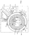
- an incubator 100 in accordance with the invention includes a ring assembly 104 having a pair of concentric rings; namely, a first or inner ring 108 and a second or outer ring 112.
- Each of the inner and outer rings 108, 112 include a plurality of circumferentially spaced incubation positions.
- the inner ring 108 is defined by a circular platen consisting of an array of pairs of radially adjacent slide element positions 116, 118, while the outer ring 112 includes a single circular array of slide element positions 122.
- a plurality of circumferential load stations are therefore defined, each load station being made up of an inner slide element position 116 and a middle or intermediate slide element position 118 each provided on the inner ring 108, as well as an outer slide element position 122 provided on the outer ring 112.
- a total of thirty-six (36) slide element positions are provided for each ring 108, 112, though it should be readily apparent that this parameter can easily be varied depending on the application.
- Each of the inner and intermediate slide element positions 116, 118 defined by the inner ring 108 include a through opening 111 that permits read access by a reflectometer or other device capable of detecting an optical property of a test sample.
- the reflectometer 153, Fig. 7 is located beneath the inner ring 108 at an inner read station 150 as described below. According to this specific embodiment, no openings are provided for any of the outer slide element positions 122 of the outer ring 112, for reasons which will become apparent below.
- a cover 126 is provided for the ring assembly 104 as partially shown in Fig. 3 .
- the cover 126 provides thermal insulation to aid in temperature control of the interior of the incubator 100.
- the inner ring 108 and the outer ring 112 are each independently driven about a common center axis of rotation.
- the inner ring 108 is a single circular plate-like member which is driven by a belt drive 130, while the outer ring 112 is rotated onto a circular track 138, Fig. 9 , using a gear drive.
- Each of the rings 108,112 are peripherally supported by a set of V-bearings 134, as partially shown in Figs. 7 and 9 , the incubator further including a hot plate 105 onto which each ring 108, 112 is mounted.
- the hot plate includes, for example, circular track 138, Fig. 9 .
- each of the rings 108, 112 of the herein described ring assembly 104 do not in and of themselves form an essential part of the present invention. That is to say, a number of different drive mechanisms could be substituted.
- An inner read station 150 includes a reflectometer 153, partially shown in Fig. 7 , which is stationarily located beneath a predetermined circumferential position 154 relative to the inner ring 108 so as to be aligned with the array of rotatably movable inner slide element positions 116.
- the inner read station 150 therefore permits the reading of either rate chemistry or endpoint colorimetric slide elements 144 at the read location 154 through the opening 111 of an aligned inner slide element position 116. Details relating to the specific operation of the reflectometer 153 and the reading of test elements in general are commonly known in the field, such as described in U.S. Patent No. 5,034,091 .
- An outer read station 160 is also provided which is radially adjacent to the outer ring 112. More specifically, the read station 160 is immediately adjacent to each of the outer slide element positions 122, the read station also being positioned at a predetermined circumferential position 164. As detailed below, an electrometer 163 (partially shown in Fig. 4 ) is provided at the outer read station 160 which allows selective access to a potentiometric slide element 140 after a predetermined incubation time when an element reaches the outer read station 160.
- the herein described incubator 100 also includes a wash module 170 located within the inner periphery of the inner ring 108 to permit immuno-rate test capability.
- the wash module 170 includes an entrance slot 176 that is aligned with a slide pusher blade assembly 188, thereby permitting a slide element 144 to be loaded into the wash station 170 directly from the rotor assembly 104.
- the wash module 170 further includes a pivoting shuttle assembly 175 which permits a loaded slide element 144 to be shuttled to a wash position 172, as shown in Fig. 6 , relative to a wash metering system (not shown) which performs washing thereof.
- the washed slide element 144 can then be shuttled back to its input position such that the slide element can be transferred back into the inner ring 108 by means of an internal pusher blade assembly 178.
- Slide or evaporator caps 174, 179 are provided for all slide positions 116, 118, 122, within the incubator 100, thereby providing evaporation and thermal control for each slide element 140, 144.
- Details relating to the general operation and function of evaporator caps in a clinical analyzer incubator, including the raising of same to load and unload same into and out of the housing through a cap holder 177, are generally known in the field as described for example in U.S. Patent No. 5,034,191, to Porte , and U.S. Patent No. 4,963,333 to Shaw, et al. , and therefore do not form an essential part of the claimed invention.
- evaporator caps 179 used for potentiometric slide elements 140 are provided for each of the outer slide element positions 122 while evaporator caps 174 used for colorimetric slide elements 144 are provided for each of the slide element positions 116, 118 of the inner ring 108.
- a total of five slide transferring devices 180, 183, 188, 192, 194 are provided in relation to a metering station 196.
- one slide transferring device 183 is located directly within the confines of a metering station 196 in order to initially shuttle a metered slide element, either a potentiometric or colorimetric slide element 140, 144, into the incubator rotor assembly 104 from a slide cartridge.
- the slide transferring device 183 operates in a manner which is commonly known, preferably using a reciprocating pusher blade.
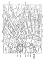
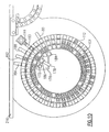
- the metering station 196 includes a metering head 198 which is disposed along the length of a metering rail 210, Figs. 10-12 .
- a metering mechanism partially shown pictorially in Figs. 10-12 permits a patient sample to be delivered along the metering rail 210 from a sample container (not shown) using a proboscis and a disposable metering tip (also not shown) so as to dispense/meter sample onto a slide element 140, 144 provided from a slide supply 204.
- the slide supply 204 retains a plurality of vertically disposed sample cartridges (not shown) which are loaded into a carousel beneath the incubator 100.
- the slide elements are incremented one at a time to the metering head 198 and are then shuttled into the outer ring 112 of the incubator 100.
- a series of bar code readers 206 arc disposed in relation to the slide supply 204 in order to properly identify the slide elements that are loaded into the incubator 100.
- Three (3) of the remaining slide transferring devices 180, 192, 194 are disposed adjacently to the metering station 196 to radially transfer slide elements 140, 144 which have been loaded into the outer ring 112. More particularly, the slide transferring devices 180, 192, and 194 are utilized to transfer non-potentiometric slide elements 144 (either rate chemistry or endpoint) to either the intermediate or inner slide element positions of the inner ring 108 or to the wash station 170.
- the remaining slide transferring device 180 is disposed on the opposite side of the metering station 196 adjacent to the read station 154.
- This specific transferring device 180 is preferably adjacent to the inner read station 150 and is used to shuttle colorimetric (e.g., rate) slide elements 144 to an inner eject slot 184 following a final read thereof in order to dispose of the slide elements which are no longer needed and further to create an empty slide element position 116 in the inner ring 108.
- colorimetric e.g., rate
- three of the slide transferring devices 180, 192, 194 include a reciprocating pusher blade 200 having an independent drive mechanism.
- the pusher blade 200 has a length dimension which permits the end of the blade to engage an edge of a slide element 140, 144 and transfer the slide element into either one of the designated slide positions of the inner and outer rings 108, 112.
- the slide transferring device 188 also includes a reciprocating pusher blade 202 which is longer than the other pusher blades 200, this device being radially aligned with the entrance slot 176 of the wash module 170.
- the outer slide positions 122 provide an incubation area for potentiometric slide elements 140, as well as certain colorimetric slide elements 144, such as those requiring endpoint testing which requires only a single read be performed at the inner read station 150 following a predetermined incubation interval (e.g., approximately 5 minutes).
- colorimetric slide elements 144 such as those requiring rate chemistries, require a number of reads to be taken by the reflectometer and are preferably shuttled to the inner slide element positions by one of the pusher blade devices 192, 194 after the slide elements 144 have been loaded into the outer ring 112.
- the incubator 100 of the present embodiment operates in the following manner.
- all spotted (metered) slide elements 140, 144 are initially loaded into the outer ring 112 of the rotor assembly 104 using the slide transferring device 183. Because the outer read station 160 is disposed in relation to the outer ring 112, potentiometric slide elements 140 are not transferred out of the outer ring 112 at any time. These slide elements 140 are therefore maintained in the outer ring 112 during the entire incubation process and are not shuttled to either of the interior slide positions 116, 118.
- the gear drive mechanism drives the outer ring 112 incrementally, meaning that the outer ring is advanced one slide position per increment.
- the outer ring 112 can be incremented or indexed by one position at a predetermined interval (e.g. approximately 4.5 seconds).
- the independently driven inner ring 108 can be driven one full revolution plus one position (N + 1) over twice the predetermined time interval (approximately 9 seconds) of the outer ring 112.
- N + 1 the predetermined time interval
- Each of the outer and inner rings 112, 108 can be synchronized at the stopping position. Therefore, the outer ring 112 will have advanced two positions while the inner ring will have advanced one position.
- the potentiometric slide element 140 is tested at the outer read station 160 by the electrometer 163 in a conventionally known manner as the potentiometric slide element passes the outer read position 164. Following the read, the potentiometric slide element 140 is no longer required according to this embodiment. Therefore, the slide element 140 subsequently passes above an outer dump station 148, shown in Fig. 9 , which is provided as a slotted portion of the circular track 138 adjacent the read station 160. As the outer ring 112 rotates in a counterclockwise direction according to the drawings, the slotted portion is exposed allowing the read slide element 140 to drop into the dump station 148.
- all reflectometer reads are taken at the read station 150 which is located in alignment with the inner slide element positions 116 as they rotate over the reflectometer 153, Fig. 7 . It is desired to get rate chemistry slide elements to the inner ring 108 as soon as possible using one of the slide element transferring devices 192, 194.
- the endpoint slide elements are shuttled using either of the slide element transferring devices 192, 194 to an intermediate slide element position 118 and subsequently to an inner slide element position 116 for reading and subsequent disposal through either eject slot 184 using the pusher blade 200 of the slide transferring device 180 or an adjacent eject slot 186, Fig. 8 , disposed adjacently to the entrance slot 176 of wash station 170 using pusher blade 202 of slide transferring device 188 following a reflectometer read at station 150, Fig. 4 .
- a spotted colorimetric slide element 144 is initially loaded into the outer ring 112 at the metering station 196.
- the slide element 144 is engaged by the pusher blade 202 of slide element transferring device 188 which pushes a slide element which is located in an inner slide element position 116 directly into the wash station 172 through the entrance slot 176 for immuno-rate wash.
- the outer ring load stations 122 are raised in relation to those of the inner ring 108 permitting the pusher blade 202 to pass beneath a potentiometric element 140, as shown more closely in Fig. 8 , without engaging therewith.
- the slide element 144 is transferred to the wash station 170 through the entrance slot 176 by means of the pusher blade 202 top an input position.
- the slide element 144 is then transferred by means of the pivotal shuttle 175 to a wash station and washed before the slide element is pivoted back to the input position and is reinserted back into the inner ring 108 through the slot 176 using the pusher blade 178.
- an empty inner slide element position 116 would have to be reserved in the inner ring 108 prior to reinsertion of the washed slide element 144.
- any of the read stations can be otherwise disposed.
- the reflectometer can be located in a read position which is fixedly held relative to the outer incubator ring.
- the electrometer can be located within the incubator; that is, radially inward of the inner ring.
- the potentiometric slide element 140 can be selectively picked from an outer slide element position 122 by means of a conventionally known picker assembly (not shown) and transferred to a read station (not shown) to then be read by the electrometer.
- the potentiometric slide element 140 following the read operation can then be shuttled by known means to an external dump station (not shown) for disposal thereof.
Landscapes
- Physics & Mathematics (AREA)
- Health & Medical Sciences (AREA)
- Life Sciences & Earth Sciences (AREA)
- Chemical & Material Sciences (AREA)
- Analytical Chemistry (AREA)
- Biochemistry (AREA)
- General Health & Medical Sciences (AREA)
- General Physics & Mathematics (AREA)
- Immunology (AREA)
- Pathology (AREA)
- Automatic Analysis And Handling Materials Therefor (AREA)
- Apparatus Associated With Microorganisms And Enzymes (AREA)
Claims (24)
- Sequenzieller Tandeminkubator (100) zur Verwendung in einer klinischen Analysevorrichtung, wobei der Inkubator umfasst:ein Inkubatorgehäuse (126);zumindest eine Lesestation (150, 160);konzentrische Innen- und Außenringe (108, 112), wobei der Außenring eine erste Vielzahl von in Umfangsrichtung angeordneten Probenaufnahmebereichen (122) und der Innenring eine zweite Vielzahl von in Umfangsrichtung angeordneten Probenaufnahmebereichen (116, 118) umfasst, wobei jeder der zweiten Vielzahl von in Umfangsrichtung angeordneten Probenaufnahmebereichen (116, 118) aus zwei radial benachbarten Probenaufnehmebereichen (116, 118) besteht, und jeder der ersten und zweiten Vielzahl von Probenaufnahmebereichen (116, 118, 122) radial benachbart zueinander auf einer gemeinsamen horizontalen Ebene liegt;zumindest einen Antriebsmechanismus (130, 134) zum unabhängigen Antreiben jedes Innen- und Außenrings (108, 112) drehbar um eine gemeinsame Achse und innerhalb einer gemeinsamen horizontalen Ebene; undzumindest zwei Gleifielement-Bewegungsvorrichtungen (180, 192, 194) zum wahlweisen Bewegen der Proben (140, 144) in einer radialen Richtung zwischen der ersten und zweiten Vielzahl der in Umfangsrichtung angeordneten Probenaufnahmebereiche (116, 118, 122), wobei jede der zumindest zwei Gleitelement-Bewegungsvorrichtungen (180, 192, 194) eine hin- und hergehende Schieberklinge (200) umfasst.
- Inkubator (100) nach Anspruch 1, wobei jeder Innen- und Außenring (108, 112) zur Drehung um eine Mittelachse des Inkubatorgehäuses (126) gelagert ist.
- Inkubator (100) nach Anspruch 2, wobei zumindest eine der zumindest zwei Gleitelement-Bewegungsvorrichtungen (192, 194) in der Lage ist, die zumindest eine Probe (140, 144) wahlweise radial von einem Probenaufnahmebereich (116, 118, 122) zu einem radial benachbarten Probenaufnahmebereich (116, 118, 122) zu bewegen.
- Inkubator (100) nach Anspruch 3, wobei zumindest eine Lesestation (150) in Bezug auf einen Innen- oder Außenring (108, 122) angeordnet ist, so dass der zumindest eine erste Antriebsmechanismus (130) einen Probenaufnahmebereich (116, 118) in eine Leseposition (154) drohen kann, wobei die zumindest eine Gleitelement-Bewegungsvorrichtung (180, 192, 194) ermöglicht, dass eine Probe wahlweise und radial von einem Gleitelement-Aufnahmebereich (116, 118, 122) zu einem radial benachbarten Gleitelement-Aufnahmebereich (116, 118, 122) und in eine Leseposition bewegt wird.
- Inkubator (100) nach einem beliebigen vorstehenden Anspruch, umfassend eine Ausgabestation (142) radial benachbart zu der Lesestation (150).
- Inkubator (100) nach einem beliebigen vorstehenden Anspruch, wobei die Lesestation (150) eine Vorrichtung (153) umfasst, die eine optische Eigenschaft einer Testprobe erfassen kann.
- Inkubator (100) nach Anspruch 6, wobei die Vorrichtung ein Reflektometer (153) ist.
- Inkubator (100) nach einem beliebigen vorstehenden Anspruch, umfassend eine zusätzliche Gleitelement-Bewegungsvorrichtung (188) zum wahlweisen und radialen Entfernen zumindest einer Probe (140, 144) aus dem Inkubator (100) für ein späteres Wiedereinsetzen in diesen.
- Inkubator (100) nach einem beliebigen vorstehenden Anspruch, wobei die Lesestation (160) eine Vorrichtung (163) umfasst, die eine elektrische Eigenschaft einer Probe messen kann.
- Inkubator (100) nach Anspruch 9, wobei die Vorrichtung ein Elektrometer (163) ist.
- Inkubator (100) nach einem beliebigen vorstehenden Anspruch, umfassend eine Vielzahl von Gleitelementen (140, 144), wobei jedes Gleitelement vor Eintritt in den Inkubator ein Volumen einer Patientenprobe mittels Fluid gemessen hat.
- Inkubator (100) nach einem beliebigen vorstehenden Anspruch, wobei zumindest eine Gleitelement-Bewegungsvorrichtung (183) ausgelegt ist, die Proben (140, 144) radial in den Inkubator (126) hin- und herzubewegen.
- Inkubator (100) nach Anspruch 12, wobei jede Gleitelement-Bewegungsvorrichtung (180, 182, 188, 192, 194) in Bezug auf eine Messstation (196) der Analysevorrichtung angeordnet ist.
- Inkubator (100) nach Anspruch 12 oder Anspruch 13, umfassend eine Zufuhr von gestapelten Proben (204), wobei eine Gleitelement-Bewegungsvorrichtung (183) angrenzend an die Probenzufuhr angeordnet ist.
- Inkubator (100) nach Anspruch 12, wobei eine Vielzahl von Gleitelement-Bewegungsvorrichtungen (188, 192, 194) an vorbestimmten Umfangspositionen angrenzend an den Außenring (112) angeordnet ist, wobei jede der Gleitelement-Bewegungsvorrichtungen (180, 192, 194) eine hin- und hergehende Schieberklinge (200) umfasst.
- Inkubator (100) nach Anspruch 15, wobei zumindest eine zusätzliche Gleitelement-Bewegungsvorrichtung (178) radial auf der Innenseite des Innenrings (108) angeordnet ist.
- Inkubator (100) nach einem vorstehenden Anspruch, wobei der zumindest eine Antriebsmechanismus (130, 134) einen Riemenantrieb (130) umfasst, der um den Umfang des Innenrings und/oder des Außenrings (108, 122) gewickelt ist.
- Inkubator (100) nach einem beliebigen vorstehenden Anspruch, wobei sich zumindest zwei Ladepositionen eines Probenaufnahmebereichs (116, 118, 122) in der Höhe in Bezug aufeinander unterscheiden.
- Verfahren zum Bebrüten und Lesen von Proben unter Verwendung eines sequenziellen Tandeminkubators (100) nach einem der Ansprüche 1 bis 18, umfassend die Schritte:radiales Laden zumindest einer Probe (140, 144) in einen leeren Probenaufnahmebereich (116, 118, 122) des Inkubators (100);Drehen des Innen- und/oder Außenrings (108, 122) um eine Mittelachse; undBewegen der zumindest einen Probe (140, 144) radial zwischen radial benachbarten Probenaufnahmebereichen (116, 118, 122) des Innen- und Außenrings (108, 112) des Inkubators (100); wobei die Schritte des radialen Ladens und des radialen Bewegens unter Verwendung von zumindest zwei Gleitelement-Bewegungsvorrichtungen (180, 192, 194) durchgeführt werden, die in Umfangsrichtung in Bezug auf den Inkubator (100) angeordnet sind, wobei jede Gleitelement-Bewegungsvorrichtung (180, 192, 194) eine hin- und hergehende Schieberklinge (200) umfasst.
- Verfahren nach Anspruch 19, umfassend die zusätzlichen Schritte:Lesen einer ersten Probe (140), die in Ausrichtung zu der Lesestation (150) gedreht wurde;radiales Antreiben einer benachbarten zweiten Probe (144) in Ausrichtung zu der Lesestation (150) unter Verwendung zumindest einer Gleitelement-Bewegungsvorrichtung (192, 194); undLesen der zweiten Probe (144).
- Verfahren nach Anspruch 20, umfassend den Schritt des Ausgebens jeder Probe (130, 144) aus dem Innenring (108) nach den Leseschritten.
- Verfahren nach Anspruch 21, umfassend den Schritt des radialen Ladens zumindest einer Probe (140, 144) vom Außenring (112) in einen leeren Gleitelement-Aufnahmebereich (112) in dem Außenring (108) nach dem Ausgabeschritt.
- Verfahren nach Anspruch 23, wobei der Ladeschritt den Schritt des gleichzeitigen radialen Hin- und Herbewegens von zumindest zwei benachbarten Testproben (140, 144) in die radial benachbarten Probenaufnahmebereiche (116, 118, 122) umfasst.
- Verfahren nach einem der Ansprüche 19 bis 23, wobei der Drehschritt ein Hochsetzen des Außenrings (112) um eine Position in einem vorbestimmten Zeitintervall und ein Antreiben des Innenrings (108) um eine volle Umdrehung plus eine Position über das Zweifache des vorbestimmten Zeitintervalls umfasst.
Applications Claiming Priority (3)
| Application Number | Priority Date | Filing Date | Title |
|---|---|---|---|
| US904692 | 1986-09-08 | ||
| US09/904,692 US7312084B2 (en) | 2001-07-13 | 2001-07-13 | Tandem incubator for clinical analyzer |
| PCT/US2002/020815 WO2003006997A2 (en) | 2001-07-13 | 2002-06-28 | Multiple track incubator for clinical analyzer |
Publications (2)
| Publication Number | Publication Date |
|---|---|
| EP1402272A2 EP1402272A2 (de) | 2004-03-31 |
| EP1402272B1 true EP1402272B1 (de) | 2010-03-24 |
Family
ID=25419581
Family Applications (1)
| Application Number | Title | Priority Date | Filing Date |
|---|---|---|---|
| EP02744770A Expired - Lifetime EP1402272B1 (de) | 2001-07-13 | 2002-06-28 | Mehrbahn-inkubator für klinische analysevorrichtung |
Country Status (10)
| Country | Link |
|---|---|
| US (1) | US7312084B2 (de) |
| EP (1) | EP1402272B1 (de) |
| JP (1) | JP4223395B2 (de) |
| KR (1) | KR20040028607A (de) |
| CN (1) | CN100339713C (de) |
| AT (1) | ATE462142T1 (de) |
| AU (1) | AU2002346018C1 (de) |
| CA (1) | CA2422741C (de) |
| DE (1) | DE60235755D1 (de) |
| WO (1) | WO2003006997A2 (de) |
Families Citing this family (23)
| Publication number | Priority date | Publication date | Assignee | Title |
|---|---|---|---|---|
| US6734401B2 (en) | 2000-06-28 | 2004-05-11 | 3M Innovative Properties Company | Enhanced sample processing devices, systems and methods |
| US6855553B1 (en) * | 2000-10-02 | 2005-02-15 | 3M Innovative Properties Company | Sample processing apparatus, methods and systems |
| US20020090321A1 (en) * | 2001-01-11 | 2002-07-11 | Fuji Photo Film Co., Ltd. | Incubator |
| US7597847B2 (en) * | 2003-03-31 | 2009-10-06 | Ortho-Clinical Diagnostics, Inc. | Analyzer having a stationary multifunction probe |
| US20040230400A1 (en) * | 2003-05-13 | 2004-11-18 | Tomasso David Angelo | Analyzer having concentric rotors |
| US8262991B2 (en) | 2003-05-19 | 2012-09-11 | Lattec I/S | Apparatus for analysing fluid taken from a body |
| US8043562B2 (en) * | 2003-12-08 | 2011-10-25 | Ortho-Clinical Diagnostics, Inc. | Analyzer having removable holders or a centrifuge |
| DE602004011334T2 (de) * | 2004-08-13 | 2009-01-08 | The Automation Partnership (Cambridge) Ltd., Royston | Rüttler-System für Zellkultur-Klimaschrank |
| US20080020467A1 (en) * | 2006-07-20 | 2008-01-24 | Lawrence Barnes | Fluid metering in a metering zone |
| US20090289128A1 (en) * | 2008-05-21 | 2009-11-26 | Ben Warren Borchert | Enhancement of fragrance release from top of candles continuity |
| US8307697B2 (en) | 2010-04-14 | 2012-11-13 | Ortho-Clinical Diagnostics, Inc. | Method for estimating viscosity |
| US20140057362A1 (en) | 2010-08-26 | 2014-02-27 | Robert J. Markovsky | Lateral flow assay analysis |
| CN103376333B (zh) * | 2012-04-17 | 2015-09-16 | 深圳迈瑞生物医疗电子股份有限公司 | 全自动生化分析仪 |
| CA2818332C (en) | 2012-06-12 | 2021-07-20 | Ortho-Clinical Diagnostics, Inc. | Lateral flow assay devices for use in clinical diagnostic apparatus and configuration of clinical diagnostic apparatus for same |
| EP3044596A4 (de) * | 2013-09-09 | 2017-03-15 | Abbott Laboratories | Systeme und verfahren zum inkubieren von proben |
| US9903858B2 (en) | 2014-07-23 | 2018-02-27 | Ortho-Clinical Diagnostics, Inc. | Multiplexing with single sample metering event to increase throughput |
| US10031085B2 (en) * | 2014-07-24 | 2018-07-24 | Ortho-Clinical Diagnostics, Inc. | Point of care analytical processing system |
| US11033896B2 (en) | 2014-08-08 | 2021-06-15 | Ortho-Clinical Diagnostics, Inc. | Lateral-flow assay device with filtration flow control |
| US10071373B2 (en) | 2014-08-08 | 2018-09-11 | Ortho-Clinical Diagnostics, Inc. | Lateral-flow assay device having flow constrictions |
| US10094842B2 (en) | 2014-10-17 | 2018-10-09 | Shenzhen Mindray Bio-Medical Electronics Co., Ltd. | Automatic biochemical analyzer |
| US11852645B2 (en) | 2017-07-07 | 2023-12-26 | Siemens Healthcare Diagnostics Inc. | Modular wash bridge for multiple-pass immunoassay systems |
| US11406981B2 (en) * | 2018-08-22 | 2022-08-09 | Biomerieux, Inc. | Detection instruments with automated cell location selection for newly intaken specimen containers and related methods |
| CN112113818B (zh) * | 2020-10-09 | 2025-09-12 | 嘉兴晶铸生物科技有限公司 | 一种恒温全自动化细胞制片一体化装置及制片方法 |
Citations (1)
| Publication number | Priority date | Publication date | Assignee | Title |
|---|---|---|---|---|
| US5244633A (en) * | 1992-05-22 | 1993-09-14 | Eastman Kodak Company | Analyzer incubator with plural independently driven rings supporting cuvettes |
Family Cites Families (53)
| Publication number | Priority date | Publication date | Assignee | Title |
|---|---|---|---|---|
| US31108A (en) * | 1861-01-15 | Improvement in subsoil plows | ||
| US31149A (en) * | 1861-01-22 | Sieve | ||
| US31150A (en) * | 1861-01-22 | Louis auguste boisson | ||
| US3193358A (en) | 1962-07-02 | 1965-07-06 | Warner Lambert Pharmacentical | Automated analytical apparatus |
| GB1051956A (de) | 1964-04-01 | |||
| DE1598191A1 (de) | 1967-06-24 | 1972-01-20 | Bodenseewerk Perkin Elmer Co | Geraet zur automatischen Durchfuehrung chemischer Analysen |
| US3636777A (en) | 1969-09-16 | 1972-01-25 | Vision Lab Inc | Laboratory beaker transporter and elevator |
| US4123173A (en) | 1976-06-09 | 1978-10-31 | Electro-Nucleonics, Inc. | Rotatable flexible cuvette arrays |
| US4067694A (en) | 1976-12-17 | 1978-01-10 | Eastman Kodak Company | Loading and unloading mechanism for continuously rotating container |
| US4152390A (en) | 1976-12-17 | 1979-05-01 | Eastman Kodak Company | Chemical analyzer |
| US4234538A (en) | 1977-10-28 | 1980-11-18 | Coulter Electronics, Inc. | Apparatus for monitoring chemical reactions and employing moving photometer means |
| US4234539A (en) | 1979-08-23 | 1980-11-18 | Coulter Electronics, Inc. | Apparatus for monitoring chemical reactions and employing moving photometer means |
| USRE31149E (en) | 1977-06-20 | 1983-02-15 | Coulter Electronics, Inc. | Apparatus for monitoring chemical reactions and employing moving photometer means |
| US4234540A (en) | 1979-08-24 | 1980-11-18 | Coulter Electronics, Inc. | Apparatus for monitoring chemical reactions and employing moving photometer means |
| USRE31150E (en) | 1977-06-20 | 1983-02-15 | Coulter Electronics, Inc. | Apparatus for monitoring chemical reactions and employing moving photometer means |
| USRE31108E (en) | 1977-06-20 | 1982-12-21 | Coulter Electronics, Inc. | Apparatus for monitoring chemical reactions and employing moving photometer means |
| US4219529A (en) | 1977-11-28 | 1980-08-26 | Eastman Kodak Company | Incubator for chemical analyzer |
| US4214968A (en) | 1978-04-05 | 1980-07-29 | Eastman Kodak Company | Ion-selective electrode |
| US4170625A (en) | 1978-05-24 | 1979-10-09 | Welch Henry H | Automatic analyzer device for carrying out chemical-clinical and kinetic-enzymatic analyses on fluids, particularly biological fluids |
| US4184936A (en) | 1978-07-24 | 1980-01-22 | Eastman Kodak Company | Device for determining ionic activity |
| US4257862A (en) | 1978-07-24 | 1981-03-24 | Eastman Kodak Company | Chemical analyzer |
| JPS55136958A (en) | 1979-04-14 | 1980-10-25 | Olympus Optical Co Ltd | Automatic analyzer |
| US4271123A (en) | 1979-10-22 | 1981-06-02 | Bio-Rad Laboratories, Inc. | Automated system for performing fluorescent immunoassays |
| US4296069A (en) | 1980-06-16 | 1981-10-20 | Eastman Kodak Company | Apparatus for processing an analysis slide |
| US4296070A (en) | 1980-06-16 | 1981-10-20 | Eastman Kodak Company | Slide distributor for a chemical analyzer |
| DE3044372A1 (de) | 1980-11-25 | 1982-07-08 | Boehringer Mannheim Gmbh, 6800 Mannheim | Rotoreinheit mit einsatzelementen fuer einen zentrifugalanalysator |
| JPS5821566A (ja) | 1981-07-31 | 1983-02-08 | Fuji Photo Film Co Ltd | インキユベ−タ |
| US4634575A (en) | 1982-10-13 | 1987-01-06 | Olympus Optical Co., Ltd. | Automatic cuvette loading apparatus |
| US4568519A (en) * | 1983-06-29 | 1986-02-04 | Eastman Kodak Company | Apparatus for processing analysis slides |
| US4552458A (en) | 1983-10-11 | 1985-11-12 | Eastman Kodak Company | Compact reflectometer |
| US4678752A (en) | 1985-11-18 | 1987-07-07 | Becton, Dickinson And Company | Automatic random access analyzer |
| US4965049A (en) | 1986-07-11 | 1990-10-23 | Beckman Instruments, Inc. | Modular analyzer system |
| JPH087220B2 (ja) | 1987-03-12 | 1996-01-29 | 富士写真フイルム株式会社 | 化学分析スライドを用いる分析方法 |
| US4817556A (en) | 1987-05-04 | 1989-04-04 | Varian Associates, Inc. | Apparatus for retaining wafers |
| US5051238A (en) | 1987-11-20 | 1991-09-24 | Hitachi, Ltd. | Automatic analyzing system |
| US5034191A (en) | 1989-01-05 | 1991-07-23 | Eastman Kodak Company | Incubator and analyzer with improved cap raising means |
| US5073342A (en) | 1989-01-05 | 1991-12-17 | Eastman Kodak Company | Reciprocating transfer mechanism |
| US5160702A (en) | 1989-01-17 | 1992-11-03 | Molecular Devices Corporation | Analyzer with improved rotor structure |
| US4963333A (en) | 1989-05-02 | 1990-10-16 | Eastman Kodak Company | Universal evaporation cover |
| DE3923833C2 (de) | 1989-07-19 | 1998-07-02 | Boehringer Mannheim Gmbh | Analysegerät für heterogene immunologische Tests |
| JPH0477669A (ja) * | 1990-07-20 | 1992-03-11 | Nittec Co Ltd | 自動分析装置 |
| TW227042B (de) | 1991-12-19 | 1994-07-21 | Eastman Kodak Co | |
| EP0555654B1 (de) | 1992-01-16 | 2002-05-02 | Fuji Photo Film Co., Ltd. | Chemisches Analysesystem |
| US6190617B1 (en) | 1992-03-27 | 2001-02-20 | Abbott Laboratories | Sample container segment assembly |
| US5376313A (en) | 1992-03-27 | 1994-12-27 | Abbott Laboratories | Injection molding a plastic assay cuvette having low birefringence |
| US5270210A (en) | 1992-07-16 | 1993-12-14 | Schiapparelli Biosystems, Inc. | Capacitive sensing system and wash/alignment station for a chemical analyzer |
| US5523056A (en) | 1994-04-29 | 1996-06-04 | Johnson & Johnson Clinical Diagnostics, Inc. | Twin rotor incubator assembly |
| US5419871A (en) | 1994-04-29 | 1995-05-30 | Muszak; Martin F. | Analyzer elevator assembly |
| US5639425A (en) | 1994-09-21 | 1997-06-17 | Hitachi, Ltd. | Analyzing apparatus having pipetting device |
| US5599501A (en) | 1994-11-10 | 1997-02-04 | Ciba Corning Diagnostics Corp. | Incubation chamber |
| US5672512A (en) | 1994-12-12 | 1997-09-30 | Johnson & Johnson Clinical Diagnostics, Inc. | Chain incubator/conveyor and method of use |
| US6156565A (en) | 1996-02-21 | 2000-12-05 | Biomerieux, Inc. | Incubation station for test sample cards |
| JP3582240B2 (ja) | 1996-06-14 | 2004-10-27 | 東ソー株式会社 | 自動検体前処理装置および自動検体前処理方法 |
-
2001
- 2001-07-13 US US09/904,692 patent/US7312084B2/en not_active Expired - Lifetime
-
2002
- 2002-06-28 DE DE60235755T patent/DE60235755D1/de not_active Expired - Lifetime
- 2002-06-28 AT AT02744770T patent/ATE462142T1/de not_active IP Right Cessation
- 2002-06-28 AU AU2002346018A patent/AU2002346018C1/en not_active Ceased
- 2002-06-28 WO PCT/US2002/020815 patent/WO2003006997A2/en not_active Ceased
- 2002-06-28 KR KR10-2003-7003673A patent/KR20040028607A/ko not_active Withdrawn
- 2002-06-28 CN CNB028027078A patent/CN100339713C/zh not_active Expired - Fee Related
- 2002-06-28 EP EP02744770A patent/EP1402272B1/de not_active Expired - Lifetime
- 2002-06-28 JP JP2003512714A patent/JP4223395B2/ja not_active Expired - Lifetime
- 2002-06-28 CA CA2422741A patent/CA2422741C/en not_active Expired - Fee Related
Patent Citations (1)
| Publication number | Priority date | Publication date | Assignee | Title |
|---|---|---|---|---|
| US5244633A (en) * | 1992-05-22 | 1993-09-14 | Eastman Kodak Company | Analyzer incubator with plural independently driven rings supporting cuvettes |
Also Published As
| Publication number | Publication date |
|---|---|
| WO2003006997A2 (en) | 2003-01-23 |
| AU2002346018B2 (en) | 2008-06-12 |
| DE60235755D1 (de) | 2010-05-06 |
| JP4223395B2 (ja) | 2009-02-12 |
| US20030017613A1 (en) | 2003-01-23 |
| AU2002346018C1 (en) | 2009-01-22 |
| EP1402272A2 (de) | 2004-03-31 |
| CA2422741C (en) | 2012-05-01 |
| JP2004534956A (ja) | 2004-11-18 |
| ATE462142T1 (de) | 2010-04-15 |
| KR20040028607A (ko) | 2004-04-03 |
| WO2003006997A3 (en) | 2003-05-22 |
| CN100339713C (zh) | 2007-09-26 |
| CN1466685A (zh) | 2004-01-07 |
| CA2422741A1 (en) | 2003-01-23 |
| US7312084B2 (en) | 2007-12-25 |
Similar Documents
| Publication | Publication Date | Title |
|---|---|---|
| EP1402272B1 (de) | Mehrbahn-inkubator für klinische analysevorrichtung | |
| AU2002346018A1 (en) | Multiple track incubator for clinical analyzer | |
| CN1576849B (zh) | 自动分析装置 | |
| US4808380A (en) | Automatic chemical analyzing apparatus | |
| CA1099951A (en) | Automatic chemical analysis of biological fluids | |
| US4224032A (en) | Method and apparatus for chemical analysis | |
| EP0517092B1 (de) | Reagenzienpackung für Immunoassays | |
| US5352612A (en) | Method and apparatus for the stepwise movement of items | |
| EP0657031B1 (de) | Vorrichtung und verfahren zur foerderung und zeitlichen lagerung von probenroehrchen bei einem automatischen chemischen analysator | |
| US6573088B2 (en) | Automated random access microbiological analyzer | |
| EP1465728B1 (de) | Stapelbare probengefässanordnung | |
| EP1325343B1 (de) | Erhöhung des durchsatzes in einem automatischen klinischen analysierer durch aufteilen von assays nach typ | |
| EP0160458B1 (de) | Vorrichtung zur automatischen chemischen Analyse | |
| RU2482498C2 (ru) | Химический анализатор, способ поочередного анализа образцов, устройство для эксплуатации кювет и способ загрузки | |
| US5320809A (en) | Retrofit kit for changing single immunoassay instrument to flexible multiple immunoassay instrument | |
| US3589867A (en) | Method and apparatus for automatically carrying out chemical analysis | |
| JPS633265A (ja) | 自動化学分析装置 | |
| US5762872A (en) | Apparatus for chemical and biochemical analysis of samples | |
| EP0576291A2 (de) | Automatische klinische Analysiervorrichtung mit Temperaturregelvorrichtung | |
| US20030040117A1 (en) | Increasing throughput in an automatic clinical analyzer by partitioning assays according to type | |
| WO1993002348A1 (en) | Reagent handling system for automated clinical analyzer apparatus | |
| JPH04350561A (ja) | 自動分析装置 |
Legal Events
| Date | Code | Title | Description |
|---|---|---|---|
| PUAI | Public reference made under article 153(3) epc to a published international application that has entered the european phase |
Free format text: ORIGINAL CODE: 0009012 |
|
| 17P | Request for examination filed |
Effective date: 20030327 |
|
| AK | Designated contracting states |
Kind code of ref document: A2 Designated state(s): AT BE CH CY DE DK ES FI FR GB GR IE IT LI LU MC NL PT SE TR |
|
| 17Q | First examination report despatched |
Effective date: 20050401 |
|
| GRAP | Despatch of communication of intention to grant a patent |
Free format text: ORIGINAL CODE: EPIDOSNIGR1 |
|
| GRAS | Grant fee paid |
Free format text: ORIGINAL CODE: EPIDOSNIGR3 |
|
| GRAA | (expected) grant |
Free format text: ORIGINAL CODE: 0009210 |
|
| AK | Designated contracting states |
Kind code of ref document: B1 Designated state(s): AT BE CH CY DE DK ES FI FR GB GR IE IT LI LU MC NL PT SE TR |
|
| REG | Reference to a national code |
Ref country code: GB Ref legal event code: FG4D |
|
| REG | Reference to a national code |
Ref country code: CH Ref legal event code: EP |
|
| REG | Reference to a national code |
Ref country code: CH Ref legal event code: NV Representative=s name: KIRKER & CIE S.A. |
|
| REG | Reference to a national code |
Ref country code: IE Ref legal event code: FG4D |
|
| REF | Corresponds to: |
Ref document number: 60235755 Country of ref document: DE Date of ref document: 20100506 Kind code of ref document: P |
|
| REG | Reference to a national code |
Ref country code: NL Ref legal event code: VDEP Effective date: 20100324 |
|
| PG25 | Lapsed in a contracting state [announced via postgrant information from national office to epo] |
Ref country code: AT Free format text: LAPSE BECAUSE OF FAILURE TO SUBMIT A TRANSLATION OF THE DESCRIPTION OR TO PAY THE FEE WITHIN THE PRESCRIBED TIME-LIMIT Effective date: 20100324 Ref country code: FI Free format text: LAPSE BECAUSE OF FAILURE TO SUBMIT A TRANSLATION OF THE DESCRIPTION OR TO PAY THE FEE WITHIN THE PRESCRIBED TIME-LIMIT Effective date: 20100324 |
|
| PG25 | Lapsed in a contracting state [announced via postgrant information from national office to epo] |
Ref country code: BE Free format text: LAPSE BECAUSE OF FAILURE TO SUBMIT A TRANSLATION OF THE DESCRIPTION OR TO PAY THE FEE WITHIN THE PRESCRIBED TIME-LIMIT Effective date: 20100324 Ref country code: GR Free format text: LAPSE BECAUSE OF FAILURE TO SUBMIT A TRANSLATION OF THE DESCRIPTION OR TO PAY THE FEE WITHIN THE PRESCRIBED TIME-LIMIT Effective date: 20100625 Ref country code: SE Free format text: LAPSE BECAUSE OF FAILURE TO SUBMIT A TRANSLATION OF THE DESCRIPTION OR TO PAY THE FEE WITHIN THE PRESCRIBED TIME-LIMIT Effective date: 20100324 Ref country code: NL Free format text: LAPSE BECAUSE OF FAILURE TO SUBMIT A TRANSLATION OF THE DESCRIPTION OR TO PAY THE FEE WITHIN THE PRESCRIBED TIME-LIMIT Effective date: 20100324 Ref country code: ES Free format text: LAPSE BECAUSE OF FAILURE TO SUBMIT A TRANSLATION OF THE DESCRIPTION OR TO PAY THE FEE WITHIN THE PRESCRIBED TIME-LIMIT Effective date: 20100705 |
|
| PLBE | No opposition filed within time limit |
Free format text: ORIGINAL CODE: 0009261 |
|
| STAA | Information on the status of an ep patent application or granted ep patent |
Free format text: STATUS: NO OPPOSITION FILED WITHIN TIME LIMIT |
|
| PG25 | Lapsed in a contracting state [announced via postgrant information from national office to epo] |
Ref country code: DK Free format text: LAPSE BECAUSE OF FAILURE TO SUBMIT A TRANSLATION OF THE DESCRIPTION OR TO PAY THE FEE WITHIN THE PRESCRIBED TIME-LIMIT Effective date: 20100324 Ref country code: MC Free format text: LAPSE BECAUSE OF NON-PAYMENT OF DUE FEES Effective date: 20100630 Ref country code: PT Free format text: LAPSE BECAUSE OF FAILURE TO SUBMIT A TRANSLATION OF THE DESCRIPTION OR TO PAY THE FEE WITHIN THE PRESCRIBED TIME-LIMIT Effective date: 20100726 |
|
| 26N | No opposition filed |
Effective date: 20101228 |
|
| PG25 | Lapsed in a contracting state [announced via postgrant information from national office to epo] |
Ref country code: IE Free format text: LAPSE BECAUSE OF NON-PAYMENT OF DUE FEES Effective date: 20100628 |
|
| PG25 | Lapsed in a contracting state [announced via postgrant information from national office to epo] |
Ref country code: CY Free format text: LAPSE BECAUSE OF FAILURE TO SUBMIT A TRANSLATION OF THE DESCRIPTION OR TO PAY THE FEE WITHIN THE PRESCRIBED TIME-LIMIT Effective date: 20100324 |
|
| PG25 | Lapsed in a contracting state [announced via postgrant information from national office to epo] |
Ref country code: LU Free format text: LAPSE BECAUSE OF NON-PAYMENT OF DUE FEES Effective date: 20100628 |
|
| PG25 | Lapsed in a contracting state [announced via postgrant information from national office to epo] |
Ref country code: TR Free format text: LAPSE BECAUSE OF FAILURE TO SUBMIT A TRANSLATION OF THE DESCRIPTION OR TO PAY THE FEE WITHIN THE PRESCRIBED TIME-LIMIT Effective date: 20100324 |
|
| REG | Reference to a national code |
Ref country code: FR Ref legal event code: PLFP Year of fee payment: 15 |
|
| REG | Reference to a national code |
Ref country code: FR Ref legal event code: PLFP Year of fee payment: 16 |
|
| PGFP | Annual fee paid to national office [announced via postgrant information from national office to epo] |
Ref country code: IT Payment date: 20170619 Year of fee payment: 16 |
|
| REG | Reference to a national code |
Ref country code: FR Ref legal event code: PLFP Year of fee payment: 17 |
|
| PGFP | Annual fee paid to national office [announced via postgrant information from national office to epo] |
Ref country code: FR Payment date: 20180511 Year of fee payment: 17 |
|
| PGFP | Annual fee paid to national office [announced via postgrant information from national office to epo] |
Ref country code: GB Payment date: 20180403 Year of fee payment: 17 |
|
| REG | Reference to a national code |
Ref country code: CH Ref legal event code: PL |
|
| PG25 | Lapsed in a contracting state [announced via postgrant information from national office to epo] |
Ref country code: IT Free format text: LAPSE BECAUSE OF NON-PAYMENT OF DUE FEES Effective date: 20180628 Ref country code: CH Free format text: LAPSE BECAUSE OF NON-PAYMENT OF DUE FEES Effective date: 20180630 Ref country code: LI Free format text: LAPSE BECAUSE OF NON-PAYMENT OF DUE FEES Effective date: 20180630 |
|
| GBPC | Gb: european patent ceased through non-payment of renewal fee |
Effective date: 20190628 |
|
| PG25 | Lapsed in a contracting state [announced via postgrant information from national office to epo] |
Ref country code: GB Free format text: LAPSE BECAUSE OF NON-PAYMENT OF DUE FEES Effective date: 20190628 |
|
| PG25 | Lapsed in a contracting state [announced via postgrant information from national office to epo] |
Ref country code: FR Free format text: LAPSE BECAUSE OF NON-PAYMENT OF DUE FEES Effective date: 20190630 |
|
| PGFP | Annual fee paid to national office [announced via postgrant information from national office to epo] |
Ref country code: DE Payment date: 20210602 Year of fee payment: 20 |
|
| REG | Reference to a national code |
Ref country code: DE Ref legal event code: R071 Ref document number: 60235755 Country of ref document: DE |