EP1465728B1 - Stapelbare probengefässanordnung - Google Patents
Stapelbare probengefässanordnung Download PDFInfo
- Publication number
- EP1465728B1 EP1465728B1 EP02797345A EP02797345A EP1465728B1 EP 1465728 B1 EP1465728 B1 EP 1465728B1 EP 02797345 A EP02797345 A EP 02797345A EP 02797345 A EP02797345 A EP 02797345A EP 1465728 B1 EP1465728 B1 EP 1465728B1
- Authority
- EP
- European Patent Office
- Prior art keywords
- array
- base plate
- aliquot vessel
- longer
- aliquot
- Prior art date
- Legal status (The legal status is an assumption and is not a legal conclusion. Google has not performed a legal analysis and makes no representation as to the accuracy of the status listed.)
- Expired - Fee Related
Links
Images


Classifications
-
- B—PERFORMING OPERATIONS; TRANSPORTING
- B01—PHYSICAL OR CHEMICAL PROCESSES OR APPARATUS IN GENERAL
- B01L—CHEMICAL OR PHYSICAL LABORATORY APPARATUS FOR GENERAL USE
- B01L3/00—Containers or dishes for laboratory use, e.g. laboratory glassware; Droppers
- B01L3/50—Containers for the purpose of retaining a material to be analysed, e.g. test tubes
- B01L3/508—Containers for the purpose of retaining a material to be analysed, e.g. test tubes rigid containers not provided for above
- B01L3/5085—Containers for the purpose of retaining a material to be analysed, e.g. test tubes rigid containers not provided for above for multiple samples, e.g. microtitration plates
-
- B—PERFORMING OPERATIONS; TRANSPORTING
- B01—PHYSICAL OR CHEMICAL PROCESSES OR APPARATUS IN GENERAL
- B01L—CHEMICAL OR PHYSICAL LABORATORY APPARATUS FOR GENERAL USE
- B01L2200/00—Solutions for specific problems relating to chemical or physical laboratory apparatus
- B01L2200/02—Adapting objects or devices to another
- B01L2200/025—Align devices or objects to ensure defined positions relative to each other
-
- B—PERFORMING OPERATIONS; TRANSPORTING
- B01—PHYSICAL OR CHEMICAL PROCESSES OR APPARATUS IN GENERAL
- B01L—CHEMICAL OR PHYSICAL LABORATORY APPARATUS FOR GENERAL USE
- B01L2300/00—Additional constructional details
- B01L2300/08—Geometry, shape and general structure
- B01L2300/0809—Geometry, shape and general structure rectangular shaped
- B01L2300/0829—Multi-well plates; Microtitration plates
-
- G—PHYSICS
- G01—MEASURING; TESTING
- G01N—INVESTIGATING OR ANALYSING MATERIALS BY DETERMINING THEIR CHEMICAL OR PHYSICAL PROPERTIES
- G01N35/00—Automatic analysis not limited to methods or materials provided for in any single one of groups G01N1/00 - G01N33/00; Handling materials therefor
- G01N35/02—Automatic analysis not limited to methods or materials provided for in any single one of groups G01N1/00 - G01N33/00; Handling materials therefor using a plurality of sample containers moved by a conveyor system past one or more treatment or analysis stations
- G01N35/04—Details of the conveyor system
- G01N2035/0401—Sample carriers, cuvettes or reaction vessels
- G01N2035/0418—Plate elements with several rows of samples
- G01N2035/0422—Plate elements with several rows of samples carried on a linear conveyor
- G01N2035/0424—Two or more linear conveyors
-
- G—PHYSICS
- G01—MEASURING; TESTING
- G01N—INVESTIGATING OR ANALYSING MATERIALS BY DETERMINING THEIR CHEMICAL OR PHYSICAL PROPERTIES
- G01N35/00—Automatic analysis not limited to methods or materials provided for in any single one of groups G01N1/00 - G01N33/00; Handling materials therefor
- G01N35/02—Automatic analysis not limited to methods or materials provided for in any single one of groups G01N1/00 - G01N33/00; Handling materials therefor using a plurality of sample containers moved by a conveyor system past one or more treatment or analysis stations
- G01N35/04—Details of the conveyor system
- G01N2035/0401—Sample carriers, cuvettes or reaction vessels
- G01N2035/0418—Plate elements with several rows of samples
- G01N2035/0425—Stacks, magazines or elevators for plates
-
- G—PHYSICS
- G01—MEASURING; TESTING
- G01N—INVESTIGATING OR ANALYSING MATERIALS BY DETERMINING THEIR CHEMICAL OR PHYSICAL PROPERTIES
- G01N35/00—Automatic analysis not limited to methods or materials provided for in any single one of groups G01N1/00 - G01N33/00; Handling materials therefor
- G01N35/02—Automatic analysis not limited to methods or materials provided for in any single one of groups G01N1/00 - G01N33/00; Handling materials therefor using a plurality of sample containers moved by a conveyor system past one or more treatment or analysis stations
- G01N35/04—Details of the conveyor system
- G01N2035/0401—Sample carriers, cuvettes or reaction vessels
- G01N2035/0427—Sample carriers, cuvettes or reaction vessels nestable or stockable
Definitions
- the present invention relates to a method and apparatus for automatically processing a patient's biological fluids such as urine, blood serum, plasma, carebrospinal fluid and the like.
- the present invention provides a stackable vessel for containing a plurality of liquid aliquot portions of patient samples in individual test wells.
- Various types of tests related to patient diagnosis and therapy can be performed by analysis assays of a sample of a patient's infections, bodily fluids or abscesses for an analyte of interest.
- patient samples are typically liquids placed in sample vials, are extracted from the vials, combined with various reagents in special reaction vessels or tubes, incubated, and analyzed to aid in treatment of the patient.
- one or two assay reagents are added at separate times to a liquid sample having a known concentration, the sample-reagent combination is mixed and incubated. Interrogating measurements, turbidimetric or fluorometric or absorption readings or the like, are made to ascertain end-point or rate values from which an amount of analyte may be determined, using well-known calibration techniques.
- An important contributor to maintaining a high efficiency in throughput of patient samples is the ability to quickly and securely introduce a plurality of samples to the sample testing portion of an analyzer.
- Patient samples are typically held in a container such as a sample cup, a primary tube, or any other suitable container and may be open at its top or closed with a stopper or lid or the like at its top.
- the containers may then be placed into a sample rack adapted to support multiple sample containers generally in an upright orientation.
- the sample rack is usually placed by an operator in an input portion of the analyzer and then moved automatically by the analyzer to a location where a portion of the liquid patient sample, hereinafter described as a aliquot, is extracted, usually by aspiration using a hollow, needle like probe from the sample container for testing in the analyzer. Afterwards, the aliquot may be dispensed directly into a sample test vessel or into an interim aliquot vessel prior to a later transfer into a sample test vessel.
- an aliquot vessel of small physical size, of low cost and with features permitting it to be reliably handled by automated devices It is particularly desirable that such an aliquot vessel be able to be transported in a one-dimension linear plane on-board an analyzer so as to eliminate the necessity and expense of two-directional handling means. It is further desirable that such an aliquot vessel be capable of easily being loaded by an operator onto an analyzer, ideally being loaded from multiple vessel put-ups. It is even further desirable that such an aliquot vessel comprise a plurality of individual aliquot wells so that a single aliquot vessel accommodate a large number of different samples, for example in an array of aliquot vessels.
- U. S. Pat. No. 6,190,617 provides for a test sample container including an upper skirt and a body having a reservoir for receipt of the test sample.
- the segment includes a base, a frame, and a handle.
- the frame has a shelf for which the upper skirt of the test sample container rests on, and has openings for receipt of the body of the sample container.
- the carousel has a carousel trough for receipt of the base of the sample container segment, and has a plurality of alignment pins disposed in the carousel trough.
- the base of the sample container segment has a circular slot and an elongated slot for receiving the alignment pins and positioning the sample container segment relative to the carousel.
- the present invention provides a aliquot vessel array adapted with a plurality of individual sample aliquot wells and capable of being attached one atop another in a secure stack.
- the sample aliquot wells are designed to minimize so-called "dead sample volume" inaccessible by typical aspiration means.
- a number of stacked aliquot vessel arrays may be simultaneously loaded by an operator into a elevator-like storage unit on an analyzer and dispensed in a singulated stream onto a sampling track as required by the analyzer.
- Handling features are designed into the aliquot vessel array to ensure safe and reliable movement between the storage unit and linear sampling tracks where sample is originally dispensed into individual wells and later aspirated therefrom for sample liquid analysis.
- the aliquot vessel array is typically covered with an evaporation and protection layer and further includes alignment features so that multiple aspirations may be made from single punctures through the protection layer.
- FIG. 1, taken with Fig. 1A, shows schematically the elements of a conventional automatic chemical analyzer 10 in which the present invention may be advantageously practiced.
- Analyzer 10 comprises a reaction carousel 12 supporting a outer cuvette circle 14 of cuvette ports 72 and 73 and an inner cuvette circle 16 of cuvette ports 74, the outer cuvette circle 14 and inner cuvette circle 16 being separated by a open groove 18.
- Cuvette ports 72, 73 and 74 are adapted to receive a plurality of reaction cuvettes 19 typically formed as small, flat walled, U-shaped containers with an open central reaction portion closed at the bottom and with an opening at the top of the cuvettes 19 to allow the addition of reagent and sample liquids.
- Reaction carousel 12 is rotatable using stepwise movements in a constant direction at a constant velocity, the stepwise movements being separated by a constant dwell time during which dwell time, carousel 12 is maintained stationary and an assay device located proximate carousel 12 may operate on an assay mixture contained within a cuvette 19.
- Three temperature-controlled reagent storage areas 20, 22 and 24 each store a plurality of reagent cartridges 21, cartridges 21, for example being a multi-compartmented reagent container like those described in U. S. Pat. No.: 4,720,374, sold under the tradename FLEX® reagent cartridge by Dade Behring Inc, Deerfield, IL., and containing reagents as necessary to perform a given assay.
- a selectively-opened lid covers each of reagent storage areas 20, 22 and 24 to allow access to cartridges 21; for simplicity, only one reagent cartridge 21 is schematically illustrated in Fig.
- reagent storage area 24 as disposed beneath a cut out portion of reagent storage area 24, however similar reagent cartridges 21 are disposed within reagent storage areas 20 and 22.
- Shuttle means (not shown) move individual cartridges 21 to probe access ports.
- Storage areas 20 and 22 may be conveniently located external to the circumference of outer cuvette circle 14 and reagent storage area 24 may be conveniently located internal to the circumference of inner cuvette circle 16.
- a clinical analyzer 10 like those on which the present invention may be performed has a plurality of conventional assay operation stations disposed proximate carousel 12 and at which are positioned individual computer controlled electromechanical devices, such as sensors, reagent add stations, mixing stations, and the like, as required to perform the myriad of actions required in well known clinical assays.
- individual computer controlled electromechanical devices such as sensors, reagent add stations, mixing stations, and the like, as required to perform the myriad of actions required in well known clinical assays.
- Such devices and their operation are well known in the art and need not be described herein. See for example, U. S. Pat. Nos. 5,876,668, 5,575,976 and 5,482,861 and the references cited therein.
- An indexing drive for the reaction carousel moves the reaction vessels in the constant direction a predetermined numbers of incremental steps.
- the length of the circumference of cuvette circle 14, the separation distance between cuvette ports 72, 73 and 74, the number of cuvette ports 72, 73 and 74, and the number of increments per indexing are selected so that any given cuvette ports 72, 73 or 74 returns to its original starting position after a fixed number of incremental steps.
- a number of liquid aspiration and dispense arms 30, 34, and 36 are located proximate the reagent storage areas 20, 22 and 24 and controlled by a programmed computer 13, preferably a microprocessor based central processing unit (CPU) to control all activities of analyzer 10 according to pre-programmed software, firmware, or hardware commands or circuits.
- CPU central processing unit
- Cuvette load and unload stations 60 and 62 are positioned proximate outer cuvette carousel 14 and are conventionally adapted to load cuvettes 19 into cavities 72, 73 and 74 seen in Fig. 1A formed in both outer cuvette carousel 14 and inner carousel 16 using for example a translatable robotic clamp 63.
- Conventional sample processing devices, or stations 17 are positioned at selected circumferential locations about the reaction carousel 12 in order to access reaction vessels 19.
- Stations 17 are adapted to provide, among other processing steps, for mixing together of the sample liquid and the reagent liquid contained in a cuvette 19, for washing the sample liquid and the reagent liquid contained in a cuvette 19, and for magnetic separation of tagged magnetic particles from free tags or reagent liquid contained in a cuvette 19.
- Incoming sample specimens to be tested are transported by a sample tube rack transport system 40 described in co-pending application Ser. No.: 9/992,917 (WO03/042048), assigned to the assignee of the present invention and after aspiration into aliquot vessel arrays 102, may be maintained within analyzer 10 inside an environmental chamber 44 described in co-pending application Ser. No.: 09/827,045 (EP-A-1417494) assigned to the assignee of the present invention.
- Specimens are typically contained in sample containers or tubes 41 supported in sample tube racks 42 and are identified by reading bar coded indicia on sample tubes 41 using a conventional bar code reader to determine, optionally among other items, a patient's identity, the tests to be performed, if a sample aliquot is desired to be retained inside environmental chamber 44 and if so, for what period of time.
- a sampling arm 46 supports a conventional liquid sampling probe 47 and is rotatably mounted so that movement of sampling arm 46 describes a line intersecting the sample tube transport system 40 and an aliquot vessel array transport system 100 adapted to transport aliquot vessel arrays 102 from an aliquot vessel array storage and handling unit 104 to a pair of conventional sample/reagent aspiration and dispense arms 50 and 52 located proximate reaction carousel 12.
- Sampling arm 46 is operable to aspirate liquid sample from sample tubes 41 and to dispense a liquid sample or an aliquot portion of the sample, into one or more of a plurality of wells 128 in aliquot vessel arrays 102, depending on the quantity of sample required to perform the requisite assays and to provide for a sample aliquot to be retained by analyzer 10 within environmental chamber 44.
- aliquot vessel array transport system 100 After sample has been dispensed into cuvettes, aliquot vessel array transport system 100 returns aliquot vessel arrays 102 to the aliquot vessel array storage and handling unit 104; a separate transport system (not shown, but located beneath aliquot vessel array transport system 100) removes aliquot vessel arrays 102 therefrom and deposits arrays 102 into storage compartment 44.
- Various assay analyzing means 70 may be located proximate outer cuvette carousel 14 and are adapted to measure light absorbence in or emission from cuvettes 15 at various wavelengths, from which the presence of analyte in the sample liquid may be determined using well-known analytical techniques.
- Means 70 typically comprise conventional photometric, fluorometric or luminescent measuring devices adapted to perform an interrogating measurement at any convenient time interval during which reaction carousel 12 is stationary.
- Drive means are provided for independently rotating outer reaction carousel 12 about an axis, the drive means typically comprising gear teeth disposed on the carousel 12 and interlacing with pinion gears mounted on the shaft of a motor.
- the drive means may be of conventional design and are not illustrated.
- Analyzer 10 is controlled by computer 13 based on software written in a machine language, like that used on the Dimension® clinical chemistry analyzer sold by Dade Behring Inc, of Deerfield, IL., and widely used by those skilled in the art of computer-based electromechanical control programming.
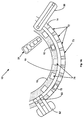
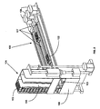
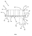
- automated aliquot vessel array storage and handling unit 104 is disposed proximate aliquot vessel array transport system 100 and is adapted in a manner described hereinafter so that aliquot vessel arrays 102 may be automatically transferred from a vertically translatable array elevator 106 from any of three aliquot vessel array inventory shafts 105 within aliquot vessel array storage unit 104 onto one of several pairs of parallel aligned aliquot vessel array sampling tracks 107.
- Aliquot vessel arrays 102 are mounted within aliquot vessel array storage unit 104 between pairs of storage tracks 103 having flared open ends 101 suitable for discharging and receiving an aliquot vessel array 102, described later in conjunction with FIG. 9.
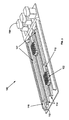
- Two aliquot vessel arrays 102 are seen located between a pair of sampling tracks 107.
- the lengthwise positioning of an aliquot vessel array 102 between sampling tracks 107 is provided by a motor-driven dolly 110 independently moveable in either direction within a pair of sampling tracks 107, the dolly 110 being connected for example by a thread-screw or ladder chain (not shown) to an independently operable stepping motor 108 (see FIG. 3).
- Each dolly 110 has a protruding and downwardly projecting finger-latch 112 adapted to secure an aliquot vessel array 102 via a zero-backlash feature described later.
- the ends of tracks 107 opposite from motors 108 are open and as seen in FIG. 3, terminate with a set of flared open ends 114 suitable for receiving an aliquot vessel array 102, described later in conjunction with FIG. 9.
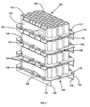
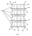
- FIG. 4 illustrates a number of the important features found in the aliquot vessel array 102 of the present invention. As seen therein, a number of aliquot vessel arrays 102 may be snapped together one atop another shown as a mutually aligned vertical stack of four aliquot vessel arrays 102.
- Each aliquot vessel array 102 comprises an orthogonal base plate 116 having a pair of upwardly extending and mutually parallel first and second side walls 118 and 119 extending lengthwise along a longer orthogonal edge 120 of the base plate 116, the side walls 118 and 119 positioned inside the outer boundary of base plate 116 and having a length shorter than the longer orthogonal edge 120 so that a longer perimeter portion 122 remains along the outermost portions of base plate 116 along the longer orthogonal edge 120 and a shorter perimeter portion 124 remains along the outermost portions of base plate 116 along a shorter front orthogonal edge 126 of the base plate 116.
- a shorter rear orthogonal edge 127 of the base plate 116 may be seen in the plan view of aliquot vessel array 102 in FIG. 7.
- An optional recessed "billboard" portion 99 may be formed in either of the first and second side walls 118 and 119 in order to frame an conventional barcode identifying indicia for the aliquot vessel array 102.
- An ordered array of open wells 128 is further formed on base plate 116 extending upwardly therefrom and confined between the pair of parallel side walls 118 and 119.
- the parallel side walls 118 are attached to the array of open wells 128 by a number of notched side flanges 121 best seen in FIG. 6 having a notch 125 adapted to mate with a foot section 138 of a rail 136.
- a pair of parallel rails 136 extend approximately the full length of the longer orthogonal edges 120 of base plate 116 and depend downwardly from the lower surfaces 115 of the base plate 116 proximate the longer orthogonal edges 120.
- base plate 116 has dimensions about 5 cm in width and 7.5 cm in length, side walls 118 are about 3-4 cm in length centered along the longer orthogonal edge 120 of the base plate 116 and extend about 1.1 cm upwardly from base plate 116.
- Wells 128 are about 0.6 cm in diameter, extend about 2 cm above base plate 116 and are about 60 in number in the embodiment described.
- aliquot vessel arrays 102 may be formed of low cost plastic material in large quantities using well known plastic molding operations and may be disposed after a single use without significantly adding to the expense of operation of analyzer 10; furthermore, the use of disposable aliquot vessel arrays 102 eliminates the possibility of sample cross-contamination created when sample aliquot holders are washed and re-used with different patient samples.
- FIGs. 4 and 5 shows how a number of aliquot vessel arrays 102 may be stacked atop one another by mating the notched side flanges 121 with the foot sections 138 of parallel rails 136 along the longer orthogonal edges 120 of base plate 116.
- Notched side flanges 121 include an inclined guide 123 leading to the notch 125 of notched side flanges 121 so that as a second aliquot vessel array 102 is pushed downwards over a first aliquot vessel array 102, the parallel rails 136 of the second aliquot vessel array 102 slide down, slightly outwards and then over inclined guides 123 so that the foot sections 138 of the rails 136 snap into notches 125, thereby securing the pair of aliquot vessel arrays 102 together. Additional aliquot vessel arrays 102 may be similarly pushed downwards over and snapped atop the pair of aliquot vessel arrays 102 so that a stack of multiple aliquot vessel arrays 102 may easily be formed.
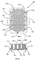
- FIG. 5 in particular shows four aliquot vessel arrays 102 snapped atop one another into a single stack.
- the purpose of this snap-together feature of the aliquot vessel array 102 of the present invention is to facilitate the loading by an operator of a number of aliquot vessel arrays 102 into the aliquot vessel array storage chutes 105 of vessel array storage and handling unit 104 as seen in FIG. 2.
- FIG. 6 is an enlarged front elevation view showing how the foot section 138 of rail 136 of the second aliquot vessel array 102 snaps over and engages the notch 125 of a notched side flange 121 of a "phantom" aliquot vessel array 102 (shown in dashed lines).
- FIG. 7 is a plan view of the aliquot vessel array 102 of the present invention showing the spatial relationships between parallel first and second side walls 118 and 119 extending lengthwise along the longer orthogonal edges 120 of the base plate 116.
- the ordered array of open wells 128 is between the pair of parallel side walls 118 and 119, separated therefrom by notched side flanges 121.
- Front orthogonal edge 126 and rear orthogonal edge 127 of the base plate 116 are further seen to be formed mutually parallel to one another with zero-backlash hitch 140 described hereinafter formed in the central region 141 of the front shorter perimeter portion 124 between the array of open wells 128 and front orthogonal edge 126. As better seen in FIG.
- each of the open wells 128 has a cylindrical shape depending downwardly from an open top and is closed at the lowermost end by conical shaped walls 128W leading to a flat circular bottom 128B.
- conical shaped walls 128W and flat circular bottom 128B have been found to be effective in minimizing liquid remaining in wells 128 during sample aspiration process.
- FIG. 7A Another important feature of the aliquot vessel array 102 of the present invention is the zero-backlash hitch 140 formed in the central region 141 of the front shorter perimeter portion 124 between the shorter orthogonal edge 126 and the array of open wells 128.
- Sectional line A-A in FIG. 7A is enlarged to show details of zero-backlash hitch 140 comprising an opening 143 in base plate 116 and a pair of semi-circular sleeves extending downwardly, a frontal sleeve 145 formed to slant backwards from the front of aliquot vessel array 102 towards a rear sleeve 147 formed generally perpendicularly to base plate 116.
- the pair of semi-circular sleeves are spaced apart a distance so that finger-latch 112 of dolly 110 may be inserted between the frontal sleeve 145 and rear sleeve 147 in such a manner that the backwards slanting frontal sleeve 145 biases finger-latch 112 against rear sleeve 147, thereby ensuring that aliquot vessel array 102 may be accurately positioned within track 107 by a ladder-chain, for example, securing dolly 110 to motor 108.
- the backwards slanting frontal sleeve 145 thereby provides zero-backlash locations to aliquot vessel array 102 throughout a repeated number of movements in both directions within track 107.
- aliquot vessel array 102 is repeatedly moved to a single sampling location in track 107 whereat multiple aliquots of sample are aspirated from wells 128, wells 128 being environmentally sealed with a conventional laminate covering (not shown) and punctured by an aspiration needle. It is important that aliquot vessel array 102 be accurately positioned within track 107 by zero-backlash hitch 140 so that only a single aspiration puncture is made in the laminate covering during multiple sample aspirations thereby minimizing sample evaporation losses during subsequent storage of the aliquot vessel array 102.
- a securing finger 130 formed in the longer perimeter portion 122 of the base plate 116 along a single longer orthogonal edge 120 proximate first parallel side wall 118 and located midway between the frontmost two of three transfer hubs 134. Securing finger 130 protrudes slightly outwards from longer orthogonal edge 120 and separated from longer perimeter portion 122 by means of a notch 132 cut within longer perimeter portion 122 between first side wall 118 and longer orthogonal edge 120 of the base plate 116.
- a securing bulge 130A is also formed in the longer perimeter portion 122 of the base plate 116 and may conveniently be located midway between the frontmost two of three transfer hubs 134.
- Securing bulge 130A protrudes slightly outwards from longer orthogonal edge 120 and is separated from longer perimeter portion 122 by means of an elongate opening 132A cut within longer perimeter portion 122 between first side wall 118 and longer orthogonal edge 120 of the base plate 116. Both securing finger 130 and securing bulge 130A act to securely retain aliquot vessel arrays 102 within array elevator 106.
- transfer hubs 134 are formed fully within and equally spaced along the longer perimeter portion 122 between the first side wall 118 and longer orthogonal edge 120, transfer hubs 134 having a solid cylindrical shape axially aligned with the plane of base plate 116 so that approximately equal portions of the transfer hubs 132 extend above and below the base plate upper surface 117 and base plate lower surface 115 of base plate 116.
- FIGs. 4 and 8A are formed fully within and equally spaced along the longer perimeter portion 122 between the first side wall 118 and longer orthogonal edge 120, transfer hubs 134 having a solid cylindrical shape axially aligned with the plane of base plate 116 so that approximately equal portions of the transfer hubs 132 extend above and below the base plate upper surface 117 and base plate lower surface 115 of base plate 116.
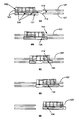
- 9A-E illustrate the utility of the three transfer hubs 134 in transferring a aliquot vessel array 102 from within an array elevator 106 to aliquot vessel array transport system 100 where sample/reagent aspiration and dispense arms 50 and 52 aspirate liquid sample from sample tubes 41 and dispense a sample aliquot into one or more of a plurality of wells 128 in aliquot vessel arrays 102.
- aliquot vessel arrays 102 supported on storage tracks 103 within array elevators 106 may be vertically positioned by array elevator 106 into approximate alignment with a pair of array sampling tracks 107 so that an aliquot vessel array 102 may be automatically and reliably transferred therebetween.
- the expense of precisely machined parts and use of multiple sensors that may otherwise be required to ensure exact alignment between the storage tracks 103 and sampling tracks 107 may be avoided by means of the three transfer hubs 134, as seen in FIGs. 9A-E.
- FIG. 9A schematically shows an aliquot vessel array 102 supported on storage tracks 103 of vessel array elevator 106 prior to removal therefrom and engaged by finger-latch 112 inserted into zero-backlash hitch 140. (Finger-latch 112 and hitch 140 are not shown in the remainder of FIG. 9 for purposes of simplicity.)
- Storage tracks 103 and sampling tracks 107 are purposefully shown as being misaligned in order to illustrate the function of the three transfer hubs 134 in FIGs. 9B-E.
- FIG. 9B shows aliquot vessel array 102 moved "rightwards" and in a position approaching the misaligned sampling tracks 107; importantly, aliquot vessel array 102 is still constrained and secured by two transfer hubs 134 engaged within tracks 103.
- FIG. 9C shows the first of three transfer hubs 134 of aliquot vessel array 102 as ramped upwards and engaged within the flared open ends 114 of sampling tracks 107. Because the aliquot vessel array 102 is being supported by circular transfer hubs 134, the aliquot vessel array 102 is free to tilt upwards or downwards with its "front end” engaged within sampling tracks 107 and its “rear end” engaged within misaligned sampling tracks 107.
- the second of three transfer hubs 134 of aliquot vessel array 102 is ramped upwards and similarly engaged within the flared open ends 114 of sampling tracks 107. The process continues until aliquot vessel array 102 is fully engaged within sampling tracks 107.
- foot sections 138 and transfer hubs 134 both enable aliquot vessel arrays 102 to be transportable in a single one-dimension linear plane on-board an analyzer so as to eliminate the necessity and expense of two-directional handling means.
- aliquot vessel arrays 102 are linearly removal from vessel array elevator 106 by finger-latch 112 sliding the notched side flanges 121 of a first aliquot vessel array 102 outwards from engagement with the foot sections 138 of a second aliquot vessel array 102 stacked atop first aliquot vessel array 102.
- Aliquot vessel arrays 102 are also linearly moveable between storage tracks 103 or sampling tracks 107 by means of transfer hubs 134 as described in FIGs. 9A-9E.
- an operator simply removes a stack of 5 to 10 aliquot vessel arrays 102 of the present invention from a shipping container and secured together by means of the notched side flanges 121 mated with foot sections 138 of a rail 136 of a next adjacent aliquot vessel arrays 102, and places them into any of three aliquot vessel array inventory shafts 105 within aliquot vessel array storage and handling unit 104.
- Array elevator 106 is controlled by CPU 13 to automatically transfer a singulated stream of aliquot vessel arrays 102 by means of zero-backlash hitch 140 coupled with finger-latch 112 of dolly 110 into one of several pairs of parallel aligned aliquot vessel array sampling tracks 107, as seen in FIG. 9.
- Each aliquot vessel array 102 is moved by motor 108 to a single sampling location in track 107 whereat multiple aliquots of liquid sample are aspirated from wells 128 of aliquot vessel arrays 102 by means of a single aspiration puncture in the laminate covering of the aliquot vessel array 102. After multiple aspirations have removed sufficient liquid sample to perform all assays requested by CPU 13, aliquot vessel arrays 102 are returned to storage and handling unit 104 and may be inventoried within analyzer 10 inside an environmental chamber 44
Claims (13)
- Teilprobengefäßanordnung zur Aufnahme mehrerer Flüssigkeitsproben von Patienten in Testvertiefungen, wobei die Anordnung Folgendes umfasst:eine Grundplatte (116) mit einer Oberseite und einer Unterseite mit einem Paar zueinander paralleler Seitenwände (118, 119), die sich von der Oberseite nach oben erstrecken, wobei diese Grundplatte des Weiteren eine darin ausgebildete spielfreie Kupplung (140) aufweist;ein Paar von der Grundplatte nach unten hängender paralleler Schienen (136), wobei jede parallele Schiene an ihrem unteren Ende einen Fußabschnitt (138) aufweist; undeine Anordnung von offenen Testvertiefungen (128), die an der Grundplatte ausgebildet sind, sich davon nach oben erstrecken und zwischen dem Paar paralleler Seitenwände eingeschlossen sind,wobei die parallelen Seitenwände durch mehrere gekerbte Seitenflansche (121) mit einer Kerbe (125), die zum Eingriff mit dem Fußabschnitt einer Schiene ausgeführt ist, an der Anordnung befestigt sind.
- Anordnung nach Anspruch 1, bei der die Grundplatte durch zueinander parallele längere Ränder, die senkrecht zu zueinander parallelen kürzeren Rändern verlaufen, definiert wird, wobei sich die zueinander parallelen Seitenwände entlang den längeren Rändern in Längsrichtung erstrecken und innerhalb der äußeren Umgrenzung der Grundplatte positioniert sind, wobei die Seitenwände kürzer sind als die längeren Ränder, so dass ein längerer Umfangsteil entlang den äußersten Teilen der Grundplatte entlang den längeren Rändern und ein kürzerer Umfangsteil entlang den äußersten Teilen der Grundplatte entlang den kürzeren Rändern bleibt.
- Anordnung nach Anspruch 2, bei der die spielfreie Kupplung im kürzeren Umfangsteil der Grundplatte ausgebildet ist.
- Anordnung nach Anspruch 2, bei der in einem längeren Umfangsteil der Grundplatte eine Befestigungsausbauchung (130A) ausgebildet ist.
- Anordnung nach Anspruch 2, bei der in einem längeren Umfangsteil der Grundplatte ein Befestigungsfinger (130) ausgebildet ist.
- Anordnung nach Anspruch 2, bei der in jedem der längeren Umfangsteile der Grundplatte zwischen einer Seitenwand und einem längeren Rand mehrere Übertragungszapfen (134) ausgebildet sind, welche eine zylindrische Form aufweisen, die axial auf die Ebene der Grundplatte ausgerichtet ist, so dass sich ungefähr gleiche Teile der Übertragungszapfen über der Ober- und der Unterseite der Grundplatte erstrecken.
- Anordnung nach Anspruch 1, bei der jede der Testvertiefungen eine zylindrische Form aufweist, die von einem offenen oberen Ende nach unten hängt und am untersten Ende durch konisch geformte Wände geschlossen ist, die zu einem flachen kreisförmigen Boden führen, um während eines Probenansaugvorgangs in Vertiefungen verbleibende Flüssigkeit zu minimieren.
- Anordnung nach Anspruch 1, bei der die spielfreie Kupplung (140) eine Öffnung (143) in der Grundplatte und ein Paar sich davon nach unten erstreckender halbkreisförmiger Hülsen (145, 147) umfasst, wobei eine Hülse so ausgebildet ist, dass sie sich von dem vorderen Ende der Anordnung nach hinten zur anderen Hülse neigt, die allgemein senkrecht zur Grundplatte ausgebildet ist, wobei das Paar halbkreisförmiger Hülsen in einem vorbestimmten Abstand voneinander angeordnet ist.
- Anordnung nach Anspruch 4, bei der die Befestigungsausbauchung von dem längeren Rand der Grundplatte etwas nach außen ragt und in dem längeren Umfangsteil zwischen der Seitenwand und dem längeren Rand der Grundplatte eine längliche Öffnung ausgebildet ist.
- Anordnung nach Anspruch 5, bei der der Befestigungsfinger von dem längeren Rand der Grundplatte etwas nach außen ragt und durch eine Kerbe, die in dem längeren Umfangsteil zwischen der Seitenwand und dem längeren Rand ausgebildet ist, von dem längeren Umfangsteil getrennt ist.
- Anordnung nach Anspruch 1, die weiterhin einen in einer Seitenwand ausgesparten Teil umfasst, um Identifizierungsangaben einzurahmen.
- Anordnung nach Anspruch 1, bei der die gekerbten Seitenflansche eine geneigte Führung umfassen, die zur Kerbe führt, so dass die parallele Schiene eines anderen Teilprobengefäßes über die geneigte Führung geschoben wird und die Fußabschnitte der Schienen in die Kerben einrasten, um dadurch das Paar von Teilprobengefäßanordnungen aneinander zu befestigen.
- Mehrere Teilprobengefäßanordnungen nach Anspruch 1, die durch Ineingriffbringen der gekerbten Seitenflansche einer Teilprobengefäßanordnung mit den Fußabschnitten paralleler Schienen einer nächsten benachbarten Teilprobengefäßanordnung aufeinander gestapelt sind.
Applications Claiming Priority (3)
| Application Number | Priority Date | Filing Date | Title |
|---|---|---|---|
| US37512 | 2002-01-04 | ||
| US10/037,512 US6752967B2 (en) | 2002-01-04 | 2002-01-04 | Stackable aliquot vessel array |
| PCT/US2002/040175 WO2003059519A1 (en) | 2002-01-04 | 2002-12-17 | Stackable aliquot vessel array |
Publications (3)
| Publication Number | Publication Date |
|---|---|
| EP1465728A1 EP1465728A1 (de) | 2004-10-13 |
| EP1465728A4 EP1465728A4 (de) | 2005-03-16 |
| EP1465728B1 true EP1465728B1 (de) | 2006-08-09 |
Family
ID=21894734
Family Applications (1)
| Application Number | Title | Priority Date | Filing Date |
|---|---|---|---|
| EP02797345A Expired - Fee Related EP1465728B1 (de) | 2002-01-04 | 2002-12-17 | Stapelbare probengefässanordnung |
Country Status (7)
| Country | Link |
|---|---|
| US (1) | US6752967B2 (de) |
| EP (1) | EP1465728B1 (de) |
| JP (1) | JP4119845B2 (de) |
| AU (1) | AU2002361707A1 (de) |
| DE (1) | DE60213873T2 (de) |
| ES (1) | ES2269803T3 (de) |
| WO (1) | WO2003059519A1 (de) |
Families Citing this family (47)
| Publication number | Priority date | Publication date | Assignee | Title |
|---|---|---|---|---|
| US7041439B2 (en) * | 2001-04-17 | 2006-05-09 | Embrex, Inc. | Methods and apparatus for selectively processing eggs having identified characteristics |
| CN1605023A (zh) * | 2001-10-19 | 2005-04-06 | 蒙诺根有限公司 | 用于获得细胞层的搅拌系统和方法 |
| US20030129755A1 (en) * | 2001-11-07 | 2003-07-10 | Genvault Corporation | System and method of storing and retrieving storage elements |
| US7584240B2 (en) * | 2001-11-07 | 2009-09-01 | Genvault Corporation | Automated biological sample archive for storage, retrieval and analysis of large numbers of samples for remote clients |
| US20030087455A1 (en) * | 2001-11-07 | 2003-05-08 | Eggers Mitchell D | Sample carrier system |
| US6808304B2 (en) * | 2002-08-27 | 2004-10-26 | Dade Behring Inc. | Method for mixing liquid samples using a linear oscillation stroke |
| US7718442B2 (en) * | 2002-11-22 | 2010-05-18 | Genvault Corporation | Sealed sample storage element system and method |
| US20100075858A1 (en) * | 2003-04-29 | 2010-03-25 | Genvault Corporation | Biological bar code |
| US7138091B2 (en) * | 2003-07-18 | 2006-11-21 | Dade Behring Inc. | Reaction cuvette having anti-wicking features for use in an automatic clinical analyzer |
| US7402281B2 (en) * | 2003-07-18 | 2008-07-22 | Siemens Healthcare Diagnostics Inc. | Magazine for inventorying reaction cuvettes in an automatic analyzer |
| US7589184B2 (en) * | 2004-05-24 | 2009-09-15 | Genvault Corporation | Stable protein storage and stable nucleic acid storage in recoverable form |
| JP2005333823A (ja) * | 2004-05-24 | 2005-12-08 | Olympus Corp | 培養容器用アダプタおよび培養処理装置 |
| JP4875066B2 (ja) * | 2005-05-06 | 2012-02-15 | カリパー・ライフ・サイエンシズ・インク. | 除去された周囲を有するマイクロタイタープレート |
| DE102006055331B4 (de) * | 2006-01-27 | 2010-12-09 | Fraunhofer-Gesellschaft zur Förderung der angewandten Forschung e.V. | Probenträger und Probenspeicher zur Kryokonservierung biologischer Proben |
| US20070253870A1 (en) * | 2006-05-01 | 2007-11-01 | Operon Biotechnologies, Inc. | Specimen tube holder and shipping container |
| US7641855B2 (en) * | 2006-08-25 | 2010-01-05 | Siemens Healthcare Diagnostics Inc. | System for automatically storing and reprocessing patient samples in an automatic clinical analyzer |
| US7506757B1 (en) * | 2007-03-21 | 2009-03-24 | Triple Hook Productions Llc | Stackable poker chip case |
| GB0724404D0 (en) * | 2007-05-29 | 2008-01-30 | Invitrogen Dynal As | A sample vessel retaining portion |
| US9199247B2 (en) * | 2007-05-29 | 2015-12-01 | Invitrogen Dynal As | Magnetic separation rack |
| WO2009100197A2 (en) | 2008-02-05 | 2009-08-13 | Pocared Diagnostics Ltd. | System for conducting the identification of bacteria in biological samples |
| WO2009126945A2 (en) | 2008-04-11 | 2009-10-15 | Pelican Group Holdings, Inc. | Pipette tip handling devices and methods |
| US20100209957A1 (en) * | 2008-06-20 | 2010-08-19 | Genvault Corporation | Biosample storage devices and methods of use thereof |
| US8283165B2 (en) | 2008-09-12 | 2012-10-09 | Genvault Corporation | Matrices and media for storage and stabilization of biomolecules |
| DE102008058755A1 (de) * | 2008-11-14 | 2010-05-27 | Pvt Probenverteiltechnik Gmbh | Rackvorrichtung für ein Probenverteilsystem |
| US8136679B2 (en) | 2009-02-03 | 2012-03-20 | Genesee Scientific Corporation | Tube reload system and components |
| JP5378859B2 (ja) * | 2009-03-30 | 2013-12-25 | シスメックス株式会社 | 検体検査システム |
| US8590736B2 (en) * | 2009-04-11 | 2013-11-26 | Biotix, Inc. | Automated pipette tip loading devices and methods |
| USD697227S1 (en) * | 2009-04-11 | 2014-01-07 | Biotix, Inc. | Pipette tip handling device set |
| US10288632B2 (en) * | 2009-09-21 | 2019-05-14 | Pocared Diagnostics Ltd. | System for conducting the identification of bacteria in biological samples |
| JP5478360B2 (ja) * | 2010-05-20 | 2014-04-23 | 株式会社日立ハイテクノロジーズ | 自動分析装置 |
| WO2012158936A1 (en) * | 2011-05-17 | 2012-11-22 | Infilco Degremont. Inc. | Method and apparatus for treating water and wastewater |
| ES2654215T3 (es) * | 2012-01-30 | 2018-02-12 | F. Hoffmann-La Roche Ag | Unidad de manipulación de gradillas de muestras |
| EP2623204A1 (de) * | 2012-02-03 | 2013-08-07 | F. Hoffmann-La Roche AG | System zur Probenhandhabung |
| US9400285B2 (en) | 2013-03-15 | 2016-07-26 | Abbot Laboratories | Automated diagnostic analyzers having vertically arranged carousels and related methods |
| CN114137240A (zh) | 2013-03-15 | 2022-03-04 | 雅培制药有限公司 | 具有后面可进入轨道系统的自动化诊断分析仪及相关方法 |
| WO2014144825A2 (en) | 2013-03-15 | 2014-09-18 | Abbott Laboratories | Automated reagent manager of a diagnostic analyzer system |
| US9513303B2 (en) | 2013-03-15 | 2016-12-06 | Abbott Laboratories | Light-blocking system for a diagnostic analyzer |
| WO2014144759A1 (en) | 2013-03-15 | 2014-09-18 | Abbott Laboratories | Linear track diagnostic analyzer |
| EP4354149A2 (de) | 2013-03-15 | 2024-04-17 | Abbott Laboratories | Diagnostische analysevorrichtung und vorbehandlungskarussells und zugehörige verfahren |
| CN105242056B (zh) * | 2014-06-04 | 2019-01-22 | 东曹株式会社 | 容器收纳托盘和自动分析装置 |
| JP6498492B2 (ja) * | 2015-03-27 | 2019-04-10 | テルモ株式会社 | 保持具およびそれを用いた滅菌方法 |
| USD804052S1 (en) * | 2015-04-17 | 2017-11-28 | Schott Kaisha Pvt., Ltd. | Nest for precrimped presterilized cartridges |
| AU2017301095B2 (en) * | 2016-07-29 | 2022-08-18 | Haemokinesis Pty. Ltd. | Storage device and assembly for vials |
| CN111328295B (zh) * | 2017-10-23 | 2022-06-17 | 豪夫迈·罗氏有限公司 | 用于自动化处理系统的多用途托盘的基本模块 |
| CN108267358A (zh) * | 2018-01-17 | 2018-07-10 | 睿科仪器(厦门)有限公司 | 一种自动加盖取盖的样品消解仪 |
| US20210127829A1 (en) * | 2018-12-21 | 2021-05-06 | Idetic Llc | Rack for supporting collection containers |
| CN113994213A (zh) * | 2019-06-24 | 2022-01-28 | 积水医疗株式会社 | 自动分析装置 |
Family Cites Families (43)
| Publication number | Priority date | Publication date | Assignee | Title |
|---|---|---|---|---|
| US938675A (en) * | 1904-12-12 | 1909-11-02 | Beech Nut Packing Co | Jar-tray. |
| US3912456A (en) * | 1974-03-04 | 1975-10-14 | Anatronics Corp | Apparatus and method for automatic chemical analysis |
| USD249706S (en) | 1976-12-17 | 1978-09-26 | Eastman Kodak Company | Sample cup tray for chemical analysis of biological fluids |
| US4178345A (en) * | 1978-02-08 | 1979-12-11 | Abbott Laboratories | Cuvette cartridge |
| US4195060A (en) * | 1978-02-08 | 1980-03-25 | Abbott Laboratories | Liquid reagent cartridge cuvette |
| US4295601A (en) * | 1979-11-13 | 1981-10-20 | Beckman Instruments, Inc. | Centrifuge tube holder |
| DE3319410A1 (de) * | 1983-05-28 | 1984-11-29 | Bodenseewerk Perkin-Elmer & Co GmbH, 7770 Überlingen | Vorrichtung zur untersuchung von umwandlungswaermen von materialproben |
| US4599314A (en) * | 1983-06-14 | 1986-07-08 | Hsc Research Development Corporation | Multiple vessel specimen tray with lid for releasably adhering vessel covers |
| JPH01500296A (ja) * | 1986-07-11 | 1989-02-02 | ベックマン インスツルメンツ インコーポレーテッド | アナライザ操作方法 |
| US5110556A (en) * | 1986-10-28 | 1992-05-05 | Costar Corporation | Multi-well test plate |
| JPH06103315B2 (ja) * | 1987-08-14 | 1994-12-14 | 株式会社東芝 | 自動化学分析装置の分注ノズル装置 |
| FR2634893B1 (fr) * | 1988-07-28 | 1990-09-14 | Guigan Jean | Laboratoire miniature pour la realisation d'analyses biologiques par reaction chimique a partir d'un echantillon de sang |
| US4877659A (en) * | 1988-08-02 | 1989-10-31 | Inti Corporation | Multiwell assay/culture strip |
| USD325975S (en) | 1990-06-01 | 1992-05-05 | Akzo N.V. | Cartridge for blood monitor |
| US6190617B1 (en) * | 1992-03-27 | 2001-02-20 | Abbott Laboratories | Sample container segment assembly |
| JP3193443B2 (ja) * | 1992-04-24 | 2001-07-30 | オリンパス光学工業株式会社 | 自動分析装置 |
| US5622675A (en) * | 1993-04-16 | 1997-04-22 | Beckman Instruments, Inc. | Sample segment |
| AU686791B2 (en) | 1994-06-03 | 1998-02-12 | Labcon, North America | Pipette tip rack loader |
| JP3228645B2 (ja) * | 1994-09-21 | 2001-11-12 | 株式会社日立製作所 | 免疫分析装置 |
| WO1996014582A1 (fr) * | 1994-11-07 | 1996-05-17 | Laboratoires Merck-Clevenot | Appareil automatique de dosage immunologique |
| US5622276A (en) * | 1995-06-01 | 1997-04-22 | Simmons; John M. | Collapsible container/cooler apparatus |
| US5735387A (en) * | 1995-07-14 | 1998-04-07 | Chiron Diagnostics Corporation | Specimen rack handling system |
| US5738827A (en) | 1995-08-23 | 1998-04-14 | Ljl Biosystems, Inc. | Apparatus for holding reagent and sample vessels |
| US5642816A (en) * | 1995-10-25 | 1997-07-01 | Rainin Instrument Co., Inc. | Pipette tip rack refill plate hold down apparatus |
| US5679309A (en) * | 1995-12-14 | 1997-10-21 | Beckman Instruments, Inc. | Automated random access analyzer |
| US5736102A (en) * | 1996-02-21 | 1998-04-07 | Biomerieux Vitek, Inc. | Test sample positioning system |
| US5948363A (en) * | 1996-04-22 | 1999-09-07 | Gaillard; Patrick | Micro-well strip with print tabs |
| MXPA99000361A (es) * | 1996-06-25 | 2006-02-10 | Foster Poultry Farms | Charolas que se apilan. |
| US5885529A (en) * | 1996-06-28 | 1999-03-23 | Dpc Cirrus, Inc. | Automated immunoassay analyzer |
| US5807523A (en) * | 1996-07-03 | 1998-09-15 | Beckman Instruments, Inc. | Automatic chemistry analyzer |
| CA2255839A1 (en) * | 1996-07-05 | 1998-01-15 | Mark Gross | Automated sample processing system |
| DE69808272T2 (de) * | 1997-05-02 | 2003-07-31 | Gen Probe Inc | Reaktion behälter apparat |
| US5961925A (en) * | 1997-09-22 | 1999-10-05 | Bristol-Myers Squibb Company | Apparatus for synthesis of multiple organic compounds with pinch valve block |
| DE19742493C1 (de) * | 1997-09-26 | 1999-02-18 | Eppendorf Geraetebau Netheler | Magazin für Pipettenspitzen |
| US6447726B1 (en) * | 1998-08-10 | 2002-09-10 | Uab Research Foundation | High density protein crystal growth |
| FR2784076B1 (fr) * | 1998-10-06 | 2000-12-22 | Gilson Sa | Ensemble comprenant des recharges de cones de pipette empilees |
| US6118582A (en) * | 1999-07-12 | 2000-09-12 | Immuno Concepts, Inc. | Slide holder |
| US6513675B1 (en) * | 2000-05-31 | 2003-02-04 | Paul Winkler Plastics Corp. | Food container with rigid base plate |
| USD452740S1 (en) | 2000-06-13 | 2002-01-01 | Dade Behring Inc. | Aliquot holder |
| AU146274S (en) | 2000-06-16 | 2001-12-13 | A I Scient Pty Ltd | Sampling tube rack |
| DE20012472U1 (de) * | 2000-07-12 | 2001-03-01 | Innova Ges Zur Entwicklung Und | Vorrichtung zur Mehrfachverdeckelung von Reaktionsgefäßen |
| ATE479499T1 (de) * | 2001-07-20 | 2010-09-15 | Gen Probe Inc Patent Dept | Probenträger und tropfschirmvorrichtung und verfahren hierfür |
| USD461554S1 (en) | 2001-08-03 | 2002-08-13 | 3088081 Canada Inc. | Test tube rack |
-
2002
- 2002-01-04 US US10/037,512 patent/US6752967B2/en not_active Expired - Fee Related
- 2002-12-17 DE DE60213873T patent/DE60213873T2/de not_active Expired - Lifetime
- 2002-12-17 WO PCT/US2002/040175 patent/WO2003059519A1/en active IP Right Grant
- 2002-12-17 ES ES02797345T patent/ES2269803T3/es not_active Expired - Lifetime
- 2002-12-17 JP JP2003559673A patent/JP4119845B2/ja not_active Expired - Fee Related
- 2002-12-17 AU AU2002361707A patent/AU2002361707A1/en not_active Abandoned
- 2002-12-17 EP EP02797345A patent/EP1465728B1/de not_active Expired - Fee Related
Also Published As
| Publication number | Publication date |
|---|---|
| EP1465728A4 (de) | 2005-03-16 |
| DE60213873T2 (de) | 2007-09-06 |
| EP1465728A1 (de) | 2004-10-13 |
| DE60213873D1 (de) | 2006-09-21 |
| WO2003059519A1 (en) | 2003-07-24 |
| US20030129095A1 (en) | 2003-07-10 |
| JP2005514633A (ja) | 2005-05-19 |
| JP4119845B2 (ja) | 2008-07-16 |
| AU2002361707A1 (en) | 2003-07-30 |
| US6752967B2 (en) | 2004-06-22 |
| ES2269803T3 (es) | 2007-04-01 |
Similar Documents
| Publication | Publication Date | Title |
|---|---|---|
| EP1465728B1 (de) | Stapelbare probengefässanordnung | |
| EP1681569B1 (de) | Diagnostisches Analysegerät als Assay-Tester | |
| US7169356B2 (en) | Random access reagent delivery system for use in an automatic clinical analyzer | |
| US6573088B2 (en) | Automated random access microbiological analyzer | |
| US8137621B2 (en) | Sample carrier for automatic loading of sample tubes for clinical analyzer | |
| US8257650B2 (en) | Automated analyzer | |
| US7015042B2 (en) | Increasing throughput in an automatic clinical analyzer by partitioning assays according to type | |
| US7402281B2 (en) | Magazine for inventorying reaction cuvettes in an automatic analyzer | |
| US6632654B1 (en) | Canister for inventorying susceptability test devices in an automated microbiological analyzer | |
| EP1346024A2 (de) | Reagensbehälter und -kanister zur verwendung in einem automatisierten mikrobiologischen analysator | |
| US20030040117A1 (en) | Increasing throughput in an automatic clinical analyzer by partitioning assays according to type | |
| US6776966B2 (en) | Canister for inventorying identification test devices in an automated microbiological analyzer | |
| US20050013743A1 (en) | I-shaped slit in a lidstock covering an array of aliquot vessels |
Legal Events
| Date | Code | Title | Description |
|---|---|---|---|
| PUAI | Public reference made under article 153(3) epc to a published international application that has entered the european phase |
Free format text: ORIGINAL CODE: 0009012 |
|
| 17P | Request for examination filed |
Effective date: 20040804 |
|
| AK | Designated contracting states |
Kind code of ref document: A1 Designated state(s): AT BE BG CH CY CZ DE DK EE ES FI FR GB GR IE IT LI LU MC NL PT SE SI SK TR |
|
| AX | Request for extension of the european patent |
Extension state: AL LT LV MK RO |
|
| A4 | Supplementary search report drawn up and despatched |
Effective date: 20050201 |
|
| GRAP | Despatch of communication of intention to grant a patent |
Free format text: ORIGINAL CODE: EPIDOSNIGR1 |
|
| RBV | Designated contracting states (corrected) |
Designated state(s): DE ES FR IT |
|
| GRAS | Grant fee paid |
Free format text: ORIGINAL CODE: EPIDOSNIGR3 |
|
| GRAA | (expected) grant |
Free format text: ORIGINAL CODE: 0009210 |
|
| AK | Designated contracting states |
Kind code of ref document: B1 Designated state(s): DE ES FR IT |
|
| AX | Request for extension of the european patent |
Extension state: RO |
|
| REF | Corresponds to: |
Ref document number: 60213873 Country of ref document: DE Date of ref document: 20060921 Kind code of ref document: P |
|
| ET | Fr: translation filed | ||
| REG | Reference to a national code |
Ref country code: ES Ref legal event code: FG2A Ref document number: 2269803 Country of ref document: ES Kind code of ref document: T3 |
|
| PLBE | No opposition filed within time limit |
Free format text: ORIGINAL CODE: 0009261 |
|
| STAA | Information on the status of an ep patent application or granted ep patent |
Free format text: STATUS: NO OPPOSITION FILED WITHIN TIME LIMIT |
|
| 26N | No opposition filed |
Effective date: 20070510 |
|
| PGFP | Annual fee paid to national office [announced via postgrant information from national office to epo] |
Ref country code: ES Payment date: 20100119 Year of fee payment: 8 Ref country code: IT Payment date: 20091222 Year of fee payment: 8 |
|
| REG | Reference to a national code |
Ref country code: ES Ref legal event code: PC2A Owner name: SIEMENS HEALTHCARE DIAGNOSTICS INC. Effective date: 20110408 |
|
| PG25 | Lapsed in a contracting state [announced via postgrant information from national office to epo] |
Ref country code: IT Free format text: LAPSE BECAUSE OF NON-PAYMENT OF DUE FEES Effective date: 20101217 |
|
| REG | Reference to a national code |
Ref country code: ES Ref legal event code: FD2A Effective date: 20120206 |
|
| REG | Reference to a national code |
Ref country code: FR Ref legal event code: TP Owner name: SIEMENS HEALTHCARE DIAGNOSTICS INC., US Effective date: 20120127 Ref country code: FR Ref legal event code: CD Owner name: SIEMENS HEALTHCARE DIAGNOSTICS INC., US Effective date: 20120127 |
|
| PG25 | Lapsed in a contracting state [announced via postgrant information from national office to epo] |
Ref country code: ES Free format text: LAPSE BECAUSE OF NON-PAYMENT OF DUE FEES Effective date: 20101218 |
|
| PGFP | Annual fee paid to national office [announced via postgrant information from national office to epo] |
Ref country code: DE Payment date: 20150220 Year of fee payment: 13 |
|
| PGFP | Annual fee paid to national office [announced via postgrant information from national office to epo] |
Ref country code: FR Payment date: 20141217 Year of fee payment: 13 |
|
| REG | Reference to a national code |
Ref country code: DE Ref legal event code: R119 Ref document number: 60213873 Country of ref document: DE |
|
| REG | Reference to a national code |
Ref country code: FR Ref legal event code: ST Effective date: 20160831 |
|
| PG25 | Lapsed in a contracting state [announced via postgrant information from national office to epo] |
Ref country code: DE Free format text: LAPSE BECAUSE OF NON-PAYMENT OF DUE FEES Effective date: 20160701 |
|
| PG25 | Lapsed in a contracting state [announced via postgrant information from national office to epo] |
Ref country code: FR Free format text: LAPSE BECAUSE OF NON-PAYMENT OF DUE FEES Effective date: 20151231 |