EP1402162B1 - Verfahren und vorrichtung zur steuerung einer brennkraftmaschine - Google Patents
Verfahren und vorrichtung zur steuerung einer brennkraftmaschine Download PDFInfo
- Publication number
- EP1402162B1 EP1402162B1 EP02745112A EP02745112A EP1402162B1 EP 1402162 B1 EP1402162 B1 EP 1402162B1 EP 02745112 A EP02745112 A EP 02745112A EP 02745112 A EP02745112 A EP 02745112A EP 1402162 B1 EP1402162 B1 EP 1402162B1
- Authority
- EP
- European Patent Office
- Prior art keywords
- controller
- internal combustion
- combustion engine
- tendency
- engine
- Prior art date
- Legal status (The legal status is an assumption and is not a legal conclusion. Google has not performed a legal analysis and makes no representation as to the accuracy of the status listed.)
- Expired - Lifetime
Links
- 238000002485 combustion reaction Methods 0.000 title claims description 24
- 238000000034 method Methods 0.000 title claims description 15
- 238000012937 correction Methods 0.000 claims description 27
- 230000001419 dependent effect Effects 0.000 claims description 9
- 230000010355 oscillation Effects 0.000 claims description 2
- 208000012661 Dyskinesia Diseases 0.000 description 8
- 230000036461 convulsion Effects 0.000 description 6
- 230000015572 biosynthetic process Effects 0.000 description 4
- 230000000694 effects Effects 0.000 description 3
- 238000010304 firing Methods 0.000 description 3
- 238000013459 approach Methods 0.000 description 2
- 239000000446 fuel Substances 0.000 description 2
- 230000004913 activation Effects 0.000 description 1
- 230000033228 biological regulation Effects 0.000 description 1
- 238000006243 chemical reaction Methods 0.000 description 1
- 230000007423 decrease Effects 0.000 description 1
- 230000003247 decreasing effect Effects 0.000 description 1
- 238000001514 detection method Methods 0.000 description 1
- 238000010586 diagram Methods 0.000 description 1
- 238000005259 measurement Methods 0.000 description 1
- 238000012545 processing Methods 0.000 description 1
Images


Classifications
-
- F—MECHANICAL ENGINEERING; LIGHTING; HEATING; WEAPONS; BLASTING
- F02—COMBUSTION ENGINES; HOT-GAS OR COMBUSTION-PRODUCT ENGINE PLANTS
- F02D—CONTROLLING COMBUSTION ENGINES
- F02D41/00—Electrical control of supply of combustible mixture or its constituents
- F02D41/0002—Controlling intake air
- F02D41/0007—Controlling intake air for control of turbo-charged or super-charged engines
-
- F—MECHANICAL ENGINEERING; LIGHTING; HEATING; WEAPONS; BLASTING
- F02—COMBUSTION ENGINES; HOT-GAS OR COMBUSTION-PRODUCT ENGINE PLANTS
- F02D—CONTROLLING COMBUSTION ENGINES
- F02D41/00—Electrical control of supply of combustible mixture or its constituents
- F02D41/02—Circuit arrangements for generating control signals
- F02D41/14—Introducing closed-loop corrections
- F02D41/1497—With detection of the mechanical response of the engine
-
- F—MECHANICAL ENGINEERING; LIGHTING; HEATING; WEAPONS; BLASTING
- F02—COMBUSTION ENGINES; HOT-GAS OR COMBUSTION-PRODUCT ENGINE PLANTS
- F02P—IGNITION, OTHER THAN COMPRESSION IGNITION, FOR INTERNAL-COMBUSTION ENGINES; TESTING OF IGNITION TIMING IN COMPRESSION-IGNITION ENGINES
- F02P5/00—Advancing or retarding ignition; Control therefor
- F02P5/04—Advancing or retarding ignition; Control therefor automatically, as a function of the working conditions of the engine or vehicle or of the atmospheric conditions
- F02P5/145—Advancing or retarding ignition; Control therefor automatically, as a function of the working conditions of the engine or vehicle or of the atmospheric conditions using electrical means
- F02P5/15—Digital data processing
- F02P5/152—Digital data processing dependent on pinking
- F02P5/1528—Digital data processing dependent on pinking for turbocompressed engine
-
- Y—GENERAL TAGGING OF NEW TECHNOLOGICAL DEVELOPMENTS; GENERAL TAGGING OF CROSS-SECTIONAL TECHNOLOGIES SPANNING OVER SEVERAL SECTIONS OF THE IPC; TECHNICAL SUBJECTS COVERED BY FORMER USPC CROSS-REFERENCE ART COLLECTIONS [XRACs] AND DIGESTS
- Y02—TECHNOLOGIES OR APPLICATIONS FOR MITIGATION OR ADAPTATION AGAINST CLIMATE CHANGE
- Y02T—CLIMATE CHANGE MITIGATION TECHNOLOGIES RELATED TO TRANSPORTATION
- Y02T10/00—Road transport of goods or passengers
- Y02T10/10—Internal combustion engine [ICE] based vehicles
- Y02T10/12—Improving ICE efficiencies
-
- Y—GENERAL TAGGING OF NEW TECHNOLOGICAL DEVELOPMENTS; GENERAL TAGGING OF CROSS-SECTIONAL TECHNOLOGIES SPANNING OVER SEVERAL SECTIONS OF THE IPC; TECHNICAL SUBJECTS COVERED BY FORMER USPC CROSS-REFERENCE ART COLLECTIONS [XRACs] AND DIGESTS
- Y02—TECHNOLOGIES OR APPLICATIONS FOR MITIGATION OR ADAPTATION AGAINST CLIMATE CHANGE
- Y02T—CLIMATE CHANGE MITIGATION TECHNOLOGIES RELATED TO TRANSPORTATION
- Y02T10/00—Road transport of goods or passengers
- Y02T10/10—Internal combustion engine [ICE] based vehicles
- Y02T10/40—Engine management systems
Definitions
- the invention relates to a method and a device for controlling an internal combustion engine.
- target size for a Output of the internal combustion engine such as torque, power, etc.
- a target size for the air supply to the internal combustion engine e.g. the filling (air mass) in the combustion chamber, educated.
- This again forms the basis for the calculation a desired angle (nominal position) of the throttle valve Internal combustion engine dar.
- an actual size for the air supply e.g., the actual charge of the engine.
- This Value forms the basis for the actual value of the output variable Internal combustion engine, for example, the actual torque.
- An example for such a procedure is for a moment-based Motor control, in which a target torque specified and by conversion into a nominal air filling or in set a target angle for the throttle is off DE-A 196 18 385 known.
- a size the deviation of the currently set ignition angle from an optimal ignition angle, preferably a torque optimal Ignition angle, represents, used.
- FIG. 1 shows an overview diagram of a control unit for Control of a supercharged internal combustion engine.
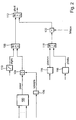
- FIG. 2 shows a flow chart for the formation of the boost pressure setpoint, which is set by a boost pressure control, wherein in case of judder or jerkiness a correction signal is formed for boost pressure reduction.
- FIG. 3 shows an exemplary embodiment to determine this correction factor the basis of ignition angle efficiency values.
- FIG. 1 shows a control device for controlling the torque or the performance of an internal combustion engine.
- the Control unit (10) comprises an input circuit (12), at least one microcomputer (14) and an output circuit (16). Input circuit, microcomputer and output circuit are via a bus system (18) to each other Data exchange connected.
- the input circuit (12) of Control unit (10) are input lines (20, 24, 28, 32 and 36-40). In a preferred embodiment are these input lines in a bus system, z. B. CAN, summarized.
- the input line connects (28) the control unit (10) with a measuring device (30) for detecting the supplied air flow, e.g. an air mass meter.
- the input line (20) connects the control unit (10) with a measuring device (22) for detection the degree of actuation of a driver operable control element, e.g. an accelerator pedal.
- the input lines 24 and 32 connect the control unit 10 to measuring devices 26 and 34 for detecting the throttle position and the Engine speed.
- measuring devices (42-46) are provided, the other operating variables of the internal combustion engine and / or the vehicle detect and corresponding measurement signals via the lines (36-40) to the control unit (10) transmit.
- Example of such operating variables are exhaust gas composition, Motor temperature, etc. via output lines and the output circuit (16) controls the control unit (10) the internal combustion engine.
- Via a first output line is an electrically operable throttle (48) for influencing actuated the air supply to the internal combustion engine.
- the Fuel supply and the ignition angle adjusts.
- a torque-based Motor control is, as from the aforementioned state known in the art, the predetermined target torque in a Target filling converted. This in turn becomes a target throttle angle determined, which by operating the throttle is set as part of a position scheme.
- a setpoint boost pressure for the boost pressure control calculated, which is set as part of the boost pressure control becomes.
- the target boost pressure is thus from Sollsaugrohrdruck and predetermined target pressure ratio at the throttle educated. The latter is based on the target intake manifold pressure value and / or the filling value and the engine speed determined and usually lies between 0.95 and 1.
- turbocharged engines tend to be more specific Operating areas to bucking. It has been shown that This is especially true in resonance areas of the spring-mass system representable engine drivetrain by scattering the moment contributions of the individual burns of the engine arises. These momentum spreads are especially at poor firing efficiencies are large, i. at late Zündwinkelein sueden. Then that's the deviation between the optimal (e.g., optimal) and the set Ignition angle particularly large. It has also been shown that the worse this ignition angle efficiency is, the steeper the torque drop. This in turn means that natural combustion scatters in this state trigger larger torque fluctuations. When charged Engines are added, that these are very knock-joyful. With increasing intake air and greater boost pressure shifts The knock limit more and more towards later ignition angles. If an engine is therefore operated without knocking, reduced by this connection the ignition angle efficiency further.
- the speed amplitude for detecting the tendency to jerk evaluated Exceeds the current speed amplitude a predetermined limit, then the deviation the speed amplitude of the limit supplied to a controller, which ensures that the controller output in accordance with the size of the deviation from high values to smaller values decreases.
- Starting value of the factor when the speed amplitude limit value is exceeded is preferably 1.
- Der vom Regulator determined factor is in the determination of the boost pressure used as a correction quantity, wherein at a value 1 the correction value is no correction, with increasing Lower values result in a lowering of the boost pressure is. Under speed amplitude is in this context the Amount of the amplitude of the speed fluctuation understood.
- the Signal processing of the controller is carried out analogously to the shown above. Ie. it will start a correction factor with 1 if the limit value falls below the threshold the deviation is made to smaller values until the Deviation exceeds the limit again.
- a pure integral controller whose output size is between a predeterminable minimum value between 0 and 1 and a Maximum value 1 can change. Is the current one Ignition angle efficiency greater than a threshold, preferably is speed-dependent, the correction factor runs in Direction of greater values, until at the upper limit, the Value 1, is stopped. Lowering the boost pressure or more general, the filling of the internal combustion engine is so ineffective.
- the controller is activated only near full load. This requires a renewed change to full load from the lower part load the correction value does not reappear be learned. By stopping the controller remains the last value in the full load range of the correction factor.
- Advantageously serves as a measure of the full load proximity the ratio of current and maximum intake manifold pressure, that for detecting the full load near a predetermined, preferably speed-dependent threshold must exceed.
- Proportional controller or proportional-integral controller used instead of a pure integral controller.
- FIG. 2 shows a flowchart is shown, which is a preferred embodiment of the determination of the boost pressure setpoint and its correction in the sense of the above representation represents.
- the flowchart represents the program a microcomputer which is part of the control unit.
- the individual blocks describe programs, program parts or program steps while the arrows control the flow of information represent.
- This target pressure value is used in other embodiments in a different way, for example, just from the Moments wish derived.
- This nominal intake manifold pressure is in a node 104 divided by the factor VPSSPLS.
- This factor represents a desired pressure ratio over the throttle and is in the preferred embodiment between 0.95 and 1.
- This factor is in a characteristic curve or a characteristic field 106 in accordance with at least an operating variable, such as the speed determined.
- the thus corrected target pressure value becomes a maximum value selection stage 108 supplied.
- the base boost pressure describes the boost pressure, the solely by the air flow and the associated operation the turbine occurs. This becomes 110 for example depending on the measure of the air mass flow, for example determined from a characteristic curve.
- the one selected in 108 Maximum value is fed to a minimum value selection stage 112, which the target boost pressure plsol as the smaller of passes both supplied values to a boost pressure control.
- the boost pressure control not shown, then regulates the target boost pressure and consideration of the actual boost pressure one.
- the maximum value selection 108 ensures that that the charging target pressure does not fall below the base boost pressure.
- the second value supplied to the minimum value selector 112 is based on at least a maximum boost pressure value calculated so that the target boost pressure is a maximum Boost pressure does not exceed.
- a maximum boost pressure value calculated so that the target boost pressure is a maximum Boost pressure does not exceed.
- FIG. 114 for example, a Characteristic curve
- In 116 which may also be a characteristic, becomes a maximum depending on the turbine speed of the supercharger Target charge pressure plxstu determined.
- the maximum value selection level 118 is made up of the two maximum values of each smaller and selected in the link 120 with corrected by the correction factor FETAZW.
- the formation of this Correction factor is based on the flowchart of Figure 3 described. It provides the correction factor described above depending on the Zündwinkel fürsgrades or Speed amplitudes to Jerklevermeidung dar. The on this Way corrected minimum value becomes
- the correction factor fetazw effects the one shown above Lowering the filling in the combustion chamber by lowering the nominal boost pressure.
- FIG. 3 shows a regulator 200, preferably an integral controller whose input ⁇ is the deviation between actual ignition angle efficiency formed in 202 and ignition angle efficiency limit.
- ⁇ is the deviation between actual ignition angle efficiency formed in 202 and ignition angle efficiency limit.
- Zündwinkel Obersgradgrenzwert is in the curve or the map or table 204 depending on the engine speed nmot read out.
- the actual ignition angle efficiency ETAZWBM is, as in the aforementioned state the technique explained by means of a Zündwinkel fürsgradkennline from the deviation of the set Kennfeldzündwinkels (speed and load dependent) and one, also determined speed and load-dependent optimum ignition angle.
- the output of the integral controller 200 represents the Correction value FETAZW.
- This output variable may vary between an applicable minimum value and a maximum value, which preferably assumes the value 1, move. Is the current firing angle ETAZWBM greater than the Limit value FETAZWLD, the integrator integrates the deviation upwards, so that the factor FETAZW increases. at If the maximum value 1 is reached, it is stopped. The filling reduction is ineffective.
- the integrator is in the preferred embodiment via an e-nable signal provided that the integrator only near full load activated, shuts off outside. Therefore, the remains last value stored in the integrator out of full load.
- recognition is used the full load near the measured intake manifold pressure PS with a maximum intake manifold pressure PLXS compared in 206.
- the amplitude the speed oscillation and its deviation from one Limit value as a controlled variable for forming the correction factor FETAZW used.
- the determined amplitude compared with a limit and the deviation one Supplied regulator, preferably an integral controller.
- This forms a correction factor between a minimum value and 1 according to the above illustration, wherein when exceeded the limit value of the correction value is lowered, when falling below the correction value is raised. Again, you can an activation close to full load makes sense.
- the amplitude is detected directly, is the limitation of Operation at full load proximity not necessary.
- the nominal intake manifold pressure, the limited nominal intake manifold pressure, or the Filling setpoint or the air supply (throttle position) adjusting value corrected by the correction factor will be suppressed and so the jerkiness.
Landscapes
- Engineering & Computer Science (AREA)
- Chemical & Material Sciences (AREA)
- Combustion & Propulsion (AREA)
- Mechanical Engineering (AREA)
- General Engineering & Computer Science (AREA)
- Signal Processing (AREA)
- Combined Controls Of Internal Combustion Engines (AREA)
- Electrical Control Of Ignition Timing (AREA)
- Output Control And Ontrol Of Special Type Engine (AREA)
- Electrical Control Of Air Or Fuel Supplied To Internal-Combustion Engine (AREA)
Description
Claims (10)
- Verfahren zur Steuerung einer Brennkraftmaschine, bei welcher die Füllung der Brennkraftmaschine beeinflusst wird, wobei ein Maß für die Ruckelneigung des Motors bzw. des Antriebsstrangs ermittelt wird, dadurch gekennzeichnet, dass ein Maß für die Ruckelneigung oder für das Ruckeln erfasst wird und einem Regler zugeführt wird, der die Füllung so lange absenkt, bis das Ruckeln verschwunden ist.
- Verfahren nach Anspruch eins, dadurch gekennzeichnet, dass die Füllung durch Absenken des Ladedrucks abgesenkt wird.
- Verfahren nach einem vorhergehenden Ansprüche, dadurch gekennzeichnet, dass die Ruckelneigung abhängig von der Amplitude einer Drehzahlschwingung oder abhängig vom Zündwinkelwirkungsgrad ermittelt wird.
- Verfahren nach Anspruch 3, dadurch gekennzeichnet, dass die Drehzahl die Motordrehzahl oder eine Drehzahl im Antriebsstrang ist.
- Verfahren nach einem vorhergehenden Ansprüche, dadurch gekennzeichnet, dass ein Korrekturfaktor gebildet wird als Ausgangsgröße des Reglers, dessen Eingangsgröße die Abweichung des Zündwinkelwirkungsgrades von einem vorgegebenen Grenzwert oder die Abweichung der Amplitude von einem vorgegebenen Grenzwert ist.
- Verfahren nach Anspruch 5, dadurch gekennzeichnet, dass die Grenzwerte drehzahlabhängig sind.
- Verfahren nach einem vorhergehenden Ansprüche, dadurch gekennzeichnet, dass der Regler nur in Volllastnähe aktiv ist.
- Verfahren nach einem vorhergehenden Ansprüche, dadurch gekennzeichnet, dass der Regler ein Integrator, ein Proportional-Integralregler oder ein Proportionalregler ist.
- Verfahren nach einem vorhergehenden Ansprüche, dadurch gekennzeichnet, dass die Volllastnähe dann erkannt ist, wenn das Verhältnis aus Saugrohrdruck und maximalen Saugrohrdruck einen vorgegebenen, vorzugsweise drehzahlabhängigen Grenzwert übersteigt.
- Vorrichtung zur Steuerung einer Brennkraftmaschine, mit einer Steuereinheit, welche Ausgangsgrößen erzeugt, welche die Füllung der Brennkraftmaschine steuern, die Steuereinheit aus Ruckelkenngrößen eine Ruckelneigung oder einen Ruckelzustand des Motors bzw. des Antriebsstrangs feststellt, dadurch gekennzeichnet, dass die Steuereinheit einen Regler umfasst, der eine Absenkung der Füllung bewirkt, wenn eine Ruckelneigung bzw. ein Ruckelzustand erkannt wird.
Applications Claiming Priority (3)
| Application Number | Priority Date | Filing Date | Title |
|---|---|---|---|
| DE10129071 | 2001-06-15 | ||
| DE10129071A DE10129071A1 (de) | 2001-06-15 | 2001-06-15 | Verfahren und Vorrichtung zur Steuerung einer Brennkraftmaschine |
| PCT/DE2002/002015 WO2002103180A1 (de) | 2001-06-15 | 2002-06-01 | Verfahren und vorrichtung zur steuerung einer brennkraftmaschine |
Publications (2)
| Publication Number | Publication Date |
|---|---|
| EP1402162A1 EP1402162A1 (de) | 2004-03-31 |
| EP1402162B1 true EP1402162B1 (de) | 2004-12-15 |
Family
ID=7688403
Family Applications (1)
| Application Number | Title | Priority Date | Filing Date |
|---|---|---|---|
| EP02745112A Expired - Lifetime EP1402162B1 (de) | 2001-06-15 | 2002-06-01 | Verfahren und vorrichtung zur steuerung einer brennkraftmaschine |
Country Status (6)
| Country | Link |
|---|---|
| EP (1) | EP1402162B1 (de) |
| JP (1) | JP4173802B2 (de) |
| CZ (1) | CZ2003408A3 (de) |
| DE (2) | DE10129071A1 (de) |
| ES (1) | ES2235057T3 (de) |
| WO (1) | WO2002103180A1 (de) |
Families Citing this family (2)
| Publication number | Priority date | Publication date | Assignee | Title |
|---|---|---|---|---|
| DE10330611B4 (de) | 2003-07-07 | 2019-05-16 | Robert Bosch Gmbh | Verfahren und Vorrichtung zum Betreiben einer Antriebseinheit mit einem Verbrennungsmotor |
| JP6406185B2 (ja) * | 2015-09-07 | 2018-10-17 | マツダ株式会社 | エンジンの制御装置 |
Family Cites Families (6)
| Publication number | Priority date | Publication date | Assignee | Title |
|---|---|---|---|---|
| DE3437324A1 (de) * | 1984-10-11 | 1986-04-24 | Robert Bosch Gmbh, 7000 Stuttgart | Verfahren und vorrichtung zur regelung der leerlaufdrehzahl bei brennkraftmaschinen |
| JPH0739818B2 (ja) * | 1989-08-31 | 1995-05-01 | 富士通テン株式会社 | 内燃機関のアイドル回転速度制御装置 |
| DE19608630A1 (de) * | 1996-03-06 | 1997-09-11 | Bosch Gmbh Robert | Verfahren und Anordnung zum Steuern oder Regeln der Leistung einer aufladbaren Brennkraftmaschine |
| DE19819049A1 (de) * | 1998-04-29 | 1999-11-25 | Daimler Chrysler Ag | Verfahren zur Vermeidung von Ruckelschwingungen beim Beschleunigen von Kraftfahrzeugen |
| DE19819050C1 (de) * | 1998-04-29 | 1999-10-14 | Daimler Chrysler Ag | Verfahren zur Vermeidung von Ruckelschwingungen beim Beschleunigen von Kraftfahrzeugen |
| DE19905604A1 (de) * | 1999-02-11 | 2000-08-17 | Bosch Gmbh Robert | Verfahren und Vorrichtung zur Dämpfung von ruckartigen Fahrzeugbewegungen |
-
2001
- 2001-06-15 DE DE10129071A patent/DE10129071A1/de not_active Withdrawn
-
2002
- 2002-06-01 JP JP2003505469A patent/JP4173802B2/ja not_active Expired - Fee Related
- 2002-06-01 CZ CZ2003408A patent/CZ2003408A3/cs unknown
- 2002-06-01 ES ES02745112T patent/ES2235057T3/es not_active Expired - Lifetime
- 2002-06-01 WO PCT/DE2002/002015 patent/WO2002103180A1/de not_active Ceased
- 2002-06-01 DE DE50201800T patent/DE50201800D1/de not_active Expired - Lifetime
- 2002-06-01 EP EP02745112A patent/EP1402162B1/de not_active Expired - Lifetime
Also Published As
| Publication number | Publication date |
|---|---|
| WO2002103180A1 (de) | 2002-12-27 |
| DE10129071A1 (de) | 2002-12-19 |
| JP2004521246A (ja) | 2004-07-15 |
| ES2235057T3 (es) | 2005-07-01 |
| CZ2003408A3 (cs) | 2003-06-18 |
| DE50201800D1 (de) | 2005-01-20 |
| EP1402162A1 (de) | 2004-03-31 |
| JP4173802B2 (ja) | 2008-10-29 |
Similar Documents
| Publication | Publication Date | Title |
|---|---|---|
| DE10016858B4 (de) | Vorrichtung zur Steuerung einer Verbrennungskraftmaschine mit einer Vorverdichtungsvorrichtung | |
| EP0937198B1 (de) | Verfahren und vorrichtung zur steuerung einer antriebseinheit eines fahrzeugs | |
| EP1440231B1 (de) | Verfahren und vorrichtung zur steuerung eines elektrisch betriebenen laders | |
| DE19924274B4 (de) | System und Verfahren zum Steuern eines Turboladers zur Maximierung der Leistung eines Verbrennungsmotors | |
| DE10329763B4 (de) | Koordinierte Regelung einer elektronischen Drosselklappe und eines Turboladers mit variabler Geometrie in ladedruckverstärkten und stöchiometrisch betriebenen Ottomotoren | |
| DE112013007145B4 (de) | Steuervorrichtung für mit Turbolader ausgerüstetem Verbrennungsmotor | |
| DE102017105454B4 (de) | Steuerungsvorrichtung für eine Verbrennungskraftmaschine | |
| DE102010054276A1 (de) | Systeme und Verfahren zur Drehzahlregelung für Verbrennungsmotoren | |
| DE102008015569B4 (de) | Maschinensteuersystem und Verfahren zum Steuern eines Maschinensteuersystems | |
| EP1317613A1 (de) | Verfahren zum betreiben einer brennkraftmaschine und entsprechende vorrichtung | |
| EP1317623A1 (de) | Verfahren zur adaptiven klopfregelung einer benzindirekteinspritzenden brennkraftmaschine und entsprechende vorrichtung | |
| EP0877152A2 (de) | Verfahren zur Regelung eines aufgeladenen Verbrennungsmotors und Vorrichtung zur Durchführung des Verfahrens | |
| DE69835549T2 (de) | Drehmomentsteuerung einer Brennkraftmaschine | |
| DE19917880A1 (de) | Regelungssystem für die einem Verbrennungsmotor zugeführte Luft | |
| DE102018103299A1 (de) | Verfahren zum auswählen des optimalen modus bei einem mehrmodusmotor mit aufladung | |
| DE102018103874A1 (de) | Steuerungsvorrichtung für einen Verbrennungsmotor und Steuerungsverfahren für einen Verbrennungsmotor | |
| DE4038252A1 (de) | Leerlaufdrehzahl-steuersystem fuer einen motor | |
| DE19947109B4 (de) | Vorrichtung und Verfahren zum Steuern von Brennkraftmaschinen | |
| DE4333896B4 (de) | Verfahren und Vorrichtung zur Steuerung einer Brennkraftmaschine | |
| DE19851457B4 (de) | Verfahren und Vorrichtung zur Steuerung des Drehmoments einer Antriebseinheit | |
| DE10114040A1 (de) | Verfahren und Vorrichtung zur Steuerung der Antriebseinheit eines Fahrzeugs | |
| DE19920498A1 (de) | Verfahren und Vorrichtung zur Steuerung einer Brennkraftmaschine | |
| DE10249098A1 (de) | Verfahren und Vorrichtung zur Steuerung einer Antriebseinheit mit einer Brennkraftmaschine | |
| DE102005004880B4 (de) | Verfahren und Vorrichtung zur Abgastemperaturregelung | |
| DE19741565B4 (de) | Verfahren und Vorrichtung zur Steuerung einer Brennkraftmaschine |
Legal Events
| Date | Code | Title | Description |
|---|---|---|---|
| PUAI | Public reference made under article 153(3) epc to a published international application that has entered the european phase |
Free format text: ORIGINAL CODE: 0009012 |
|
| 17P | Request for examination filed |
Effective date: 20040115 |
|
| AK | Designated contracting states |
Kind code of ref document: A1 Designated state(s): AT BE CH CY DE DK ES FI FR GB GR IE IT LI LU MC NL PT SE |
|
| GRAP | Despatch of communication of intention to grant a patent |
Free format text: ORIGINAL CODE: EPIDOSNIGR1 |
|
| GRAA | (expected) grant |
Free format text: ORIGINAL CODE: 0009210 |
|
| GRAS | Grant fee paid |
Free format text: ORIGINAL CODE: EPIDOSNIGR3 |
|
| AK | Designated contracting states |
Kind code of ref document: B1 Designated state(s): DE ES FR GB IT SE |
|
| REG | Reference to a national code |
Ref country code: GB Ref legal event code: FG4D Free format text: NOT ENGLISH |
|
| REG | Reference to a national code |
Ref country code: IE Ref legal event code: FG4D Free format text: GERMAN |
|
| REF | Corresponds to: |
Ref document number: 50201800 Country of ref document: DE Date of ref document: 20050120 Kind code of ref document: P |
|
| REG | Reference to a national code |
Ref country code: SE Ref legal event code: TRGR |
|
| GBT | Gb: translation of ep patent filed (gb section 77(6)(a)/1977) |
Effective date: 20050404 |
|
| REG | Reference to a national code |
Ref country code: ES Ref legal event code: FG2A Ref document number: 2235057 Country of ref document: ES Kind code of ref document: T3 |
|
| PLBE | No opposition filed within time limit |
Free format text: ORIGINAL CODE: 0009261 |
|
| STAA | Information on the status of an ep patent application or granted ep patent |
Free format text: STATUS: NO OPPOSITION FILED WITHIN TIME LIMIT |
|
| ET | Fr: translation filed | ||
| 26N | No opposition filed |
Effective date: 20050916 |
|
| PGFP | Annual fee paid to national office [announced via postgrant information from national office to epo] |
Ref country code: SE Payment date: 20120625 Year of fee payment: 11 Ref country code: GB Payment date: 20120621 Year of fee payment: 11 Ref country code: FR Payment date: 20120705 Year of fee payment: 11 |
|
| PGFP | Annual fee paid to national office [announced via postgrant information from national office to epo] |
Ref country code: IT Payment date: 20120626 Year of fee payment: 11 |
|
| PGFP | Annual fee paid to national office [announced via postgrant information from national office to epo] |
Ref country code: ES Payment date: 20120628 Year of fee payment: 11 |
|
| PG25 | Lapsed in a contracting state [announced via postgrant information from national office to epo] |
Ref country code: SE Free format text: LAPSE BECAUSE OF NON-PAYMENT OF DUE FEES Effective date: 20130602 |
|
| REG | Reference to a national code |
Ref country code: SE Ref legal event code: EUG |
|
| GBPC | Gb: european patent ceased through non-payment of renewal fee |
Effective date: 20130601 |
|
| REG | Reference to a national code |
Ref country code: FR Ref legal event code: ST Effective date: 20140228 |
|
| PG25 | Lapsed in a contracting state [announced via postgrant information from national office to epo] |
Ref country code: GB Free format text: LAPSE BECAUSE OF NON-PAYMENT OF DUE FEES Effective date: 20130601 |
|
| PG25 | Lapsed in a contracting state [announced via postgrant information from national office to epo] |
Ref country code: IT Free format text: LAPSE BECAUSE OF NON-PAYMENT OF DUE FEES Effective date: 20130601 Ref country code: FR Free format text: LAPSE BECAUSE OF NON-PAYMENT OF DUE FEES Effective date: 20130701 |
|
| REG | Reference to a national code |
Ref country code: ES Ref legal event code: FD2A Effective date: 20140707 |
|
| PG25 | Lapsed in a contracting state [announced via postgrant information from national office to epo] |
Ref country code: ES Free format text: LAPSE BECAUSE OF NON-PAYMENT OF DUE FEES Effective date: 20130602 |
|
| REG | Reference to a national code |
Ref country code: DE Ref legal event code: R084 Ref document number: 50201800 Country of ref document: DE |
|
| PGFP | Annual fee paid to national office [announced via postgrant information from national office to epo] |
Ref country code: DE Payment date: 20190822 Year of fee payment: 18 |
|
| REG | Reference to a national code |
Ref country code: DE Ref legal event code: R119 Ref document number: 50201800 Country of ref document: DE |
|
| PG25 | Lapsed in a contracting state [announced via postgrant information from national office to epo] |
Ref country code: DE Free format text: LAPSE BECAUSE OF NON-PAYMENT OF DUE FEES Effective date: 20210101 |