EP1400670B1 - Procédé et dispositif pour controller un turbocompresseur - Google Patents
Procédé et dispositif pour controller un turbocompresseur Download PDFInfo
- Publication number
- EP1400670B1 EP1400670B1 EP02405822A EP02405822A EP1400670B1 EP 1400670 B1 EP1400670 B1 EP 1400670B1 EP 02405822 A EP02405822 A EP 02405822A EP 02405822 A EP02405822 A EP 02405822A EP 1400670 B1 EP1400670 B1 EP 1400670B1
- Authority
- EP
- European Patent Office
- Prior art keywords
- compressor
- line
- flow
- upstream
- downstream
- Prior art date
- Legal status (The legal status is an assumption and is not a legal conclusion. Google has not performed a legal analysis and makes no representation as to the accuracy of the status listed.)
- Expired - Lifetime
Links
Images


Classifications
-
- F—MECHANICAL ENGINEERING; LIGHTING; HEATING; WEAPONS; BLASTING
- F02—COMBUSTION ENGINES; HOT-GAS OR COMBUSTION-PRODUCT ENGINE PLANTS
- F02B—INTERNAL-COMBUSTION PISTON ENGINES; COMBUSTION ENGINES IN GENERAL
- F02B37/00—Engines characterised by provision of pumps driven at least for part of the time by exhaust
- F02B37/12—Control of the pumps
- F02B37/16—Control of the pumps by bypassing charging air
-
- F—MECHANICAL ENGINEERING; LIGHTING; HEATING; WEAPONS; BLASTING
- F02—COMBUSTION ENGINES; HOT-GAS OR COMBUSTION-PRODUCT ENGINE PLANTS
- F02D—CONTROLLING COMBUSTION ENGINES
- F02D41/00—Electrical control of supply of combustible mixture or its constituents
- F02D41/0002—Controlling intake air
- F02D41/0007—Controlling intake air for control of turbo-charged or super-charged engines
-
- Y—GENERAL TAGGING OF NEW TECHNOLOGICAL DEVELOPMENTS; GENERAL TAGGING OF CROSS-SECTIONAL TECHNOLOGIES SPANNING OVER SEVERAL SECTIONS OF THE IPC; TECHNICAL SUBJECTS COVERED BY FORMER USPC CROSS-REFERENCE ART COLLECTIONS [XRACs] AND DIGESTS
- Y02—TECHNOLOGIES OR APPLICATIONS FOR MITIGATION OR ADAPTATION AGAINST CLIMATE CHANGE
- Y02T—CLIMATE CHANGE MITIGATION TECHNOLOGIES RELATED TO TRANSPORTATION
- Y02T10/00—Road transport of goods or passengers
- Y02T10/10—Internal combustion engine [ICE] based vehicles
- Y02T10/12—Improving ICE efficiencies
Definitions
- the invention relates to the operation of an exhaust gas turbocharger. It relates in particular to a method for operating an exhaust gas turbocharger according to the features of the preamble of claim 1, an apparatus for performing this method according to the features of the preamble of claim 5 and an exhaust gas turbocharger with such a device.
- Exhaust gas turbochargers are used to charge internal combustion engines, with a turbine driven by the exhaust gas of the exhaust gas turbocharger via a common shaft drives a compressor.
- the compressor sucks in a gas via a suction line, usually air or a mixture of air and a gas, usually fuel gas and / or exhaust gas, and compacted this.
- a suction line usually air or a mixture of air and a gas, usually fuel gas and / or exhaust gas, and compacted this.
- a downstream of the compressor compressor line connected with is connected to an intake port of the internal combustion engine, the compressed gas Combustion chambers of the internal combustion engine supplied.
- the amount of gas supplied to the combustion chambers determines such as the setting and distribution of the fuel mixture and the ignition timing, the current performance of the internal combustion engine substantially with. This means that for example, during a load, during startup or acceleration of the Machine, the highest possible amount of gas supplied and when throttling the machine as possible should be worked with a reduced amount of gas.
- the Gas quantity, which is supplied to the combustion chambers of the internal combustion engine, with the aid of a Regulated throttle, which is located downstream of the compressor in front of the combustion chambers is, for example, in the article "New high efficiency high speed gas engine the 3MW class "shown in CIMAC Congress 1998 Copenhagen, page 1393, Fig. 9 or MTZ Motortechnische Zeitschrift 50 (1989) 5, page 231, Figure 7 is described.
- bypass lines are the area between the compressor and the throttle valve downstream of the compressor with the suction line connect upstream of the compressor, and an outflow of the compressed gas from the Area between compressor and throttle valve back into the intake line upstream of the Allow compressor.
- bypass lines are described in DE-A-28 23 067 and DE-A-197 28 850.
- bypass valves In order to use the bypass line targeted are in the bypass line one or more bypass valves provided.
- the control of these bypass valves works essentially pressure controlled. The occurring pressure differences become partly used directly by pressure valves, even pressures from the exhaust area of the system. In part, the control is also electronic besides the pressure data also temperature, speed and other data of the Systems are considered.
- valves are controlled in the bypass line and in the line in which the Compressor is arranged electronically. These are the most diverse operating data of turbocharger and internal combustion engine, detected by sensors, processed in a control unit and output a corresponding control signal to the valves in the two lines.
- GB 2 083 135 also discloses an apparatus for operating an exhaust gas turbocharger, in which the bypass line is controlled by a valve flow around the compressing Elements from its upstream side to its downstream Page allowed.
- the object of the invention is therefore to provide a simple, inexpensive method for operating an exhaust gas turbocharger, in which the Auflade Ecksgrad the exhaust gas turbocharger is improved when the load of the internal combustion engine. Furthermore, a technically very simple and therefore cost-effective device for carrying out this method is presented.
- US Pat method according to the invention a main flow of a gas via a suction line fed to a compressor of the exhaust gas turbocharger, compressed in the compressor and via a Compressor introduced into an intake passage of the internal combustion engine, wherein the over the Intake duct to combustion chambers of the internal combustion engine forwarded gas quantity by means of regulated between the compressor and the combustion chambers arranged throttle becomes.
- This method is very simple to carry out with a device according to the invention which can be connected to a conventional system of internal combustion engine and exhaust gas turbocharger.
- the conventional system of internal combustion engine and exhaust gas turbocharger has an exhaust gas turbocharger with a driven by a turbine compressor. The latter is upstream connected to a suction line and downstream to a compressor line.
- the compressor line can be connected to an intake passage of the internal combustion engine to form a flow line, wherein a throttle valve is provided in the flow line.
- the inventive device comprises a bypass line which is connected in the assembled state on its first side with the intake line upstream of the compressor and with its second side between the compressor and the throttle valve with the flow line.
- the bypass line is designed such that it allows only a flow around the compressor from the upstream side to the downstream side of the compressor.
- at least one control element which allows a flow only from the upstream side to the downstream side of the compressor, for example, a check valve is provided, but prevents flow in the opposite direction.
- the check valve is designed as a pressure-sensitive valve and acted upon from the one side with the pressure p1 and from the other side with the pressure p2. This allows a very simple, self-resulting control which is not susceptible to interference and, moreover, very inexpensive.
- Options for the design of such a check valve for example, a spring-supported ball or poppet valve.
- the inventive device can be provided in new turbochargers, they But it is also suitable for retrofitting existing exhaust gas turbochargers.
- bypass line is then advantageously connected to the compressor line downstream of the compressor, so that they do not separate with the intake duct of the internal combustion engine during assembly must be connected.
- the second side of the bypass line is not connected to the compressor line of the exhaust gas turbocharger but for a Connection with the intake port of the internal combustion engine is designed.
- the throttle must be arranged in the intake passage of the internal combustion engine, and the Bypass line must still be installed upstream of the throttle valve with the intake duct during assembly the internal combustion engine are connected.
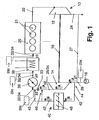
- FIG. 1 shows an exhaust gas turbocharger 10 with a turbine 12 and a compressor 14, Turbine 12 and compressor 14 are arranged on a common shaft 16. From one Internal combustion engine 20 with combustion chambers 21 leads an exhaust gas line 22 to the turbine 12. Exhaust gases are supplied to the turbine via the exhaust gas line 22, which drive the turbine 12. so that over the common shaft 16 and the compressor 14 starts to work. About a derivative 24, the exhaust gases are discharged downstream of the turbine 12.
- the compressor 14 draws air via an upstream intake pipe 26 under the Pressure p1 on. As indicated by the dashed line 27, it is also possible to divert a portion of the exhaust gas by means of a connecting line from the derivative 24 and to mix in the air drawn in via the suction line upstream of the compressor 14. Also, the sucked air from a fuel gas tank 29a, 29b, 29c, 29d be mixed with a fuel gas. This admixture can be both upstream of the 29a Compressor 14, as well as at various locations downstream of 29b, 29c, 29d of the compressor carried out (indicated by dashed lines).
- a compressor line 28 Sucked in air as well as an air exhaust and Air fuel gas mixture or a mixture of air, fuel gas and exhaust gas are gases, therefore continue to be spoken only by gas.
- the sucked gas is over the Compressor 14 out, compressed by this, and fed downstream in a compressor line 28.
- the compressor line 28 is by means of a flange 30 with an intake passage 32 of the internal combustion engine 20 is connected. Together make up compressor line 28 and intake 32, a flow line 34 in which a throttle valve 36 is arranged is.
- the throttle 36 in the compressor line 28 of the exhaust gas turbocharger 10 instead of the intake passage 32nd the internal combustion engine 20 is arranged. Downstream of the throttle 36 is in the here shown example, a charge air cooler 38 is arranged. Downstream of the intercooler 38 is the Intake passage 32 is connected to the combustion chambers 21 of the internal combustion engine 20.
- the exhaust gas turbocharger 10 has an inventive device 40 with a bypass line 42 on the first side 44 with the suction line 26 upstream of the compressor 14 and with its second side 46 downstream of the compressor between the compressor 14 and the throttle valve 36 is connected to the compressor line 28.
- the second side 46 of the bypass line 42 between the compressor 14 and the throttle valve 36 to connect with the intake passage 32 instead of the compressor line 28, as this is indicated by the dashed line 43.
- the bypass line 42, 43 is simple Non-return valves 48 equipped only a flow around the compressor 14 of the upstream side to the downstream side of the compressor 14 allow.
- the check valves 48 open automatically when the ambient pressure p1 gets bigger than that prevailing in the area between compressor 14 and throttle valve 36 Pressure p2. This happens each time the throttle 36 is fully opened, such as in FIG. when starting the engine 20; but above all, it is also very efficient when taking a load from idling, because then the slowly rotating compressor 14 as a throttle acts.
- bypass flow B which is branched off from the main flow A upstream of the compressor 14.
- the bypass flow B derived from the main flow A passes through the bypass line 42, 43 from the upstream side around the compressor 14 to the downstream Side of the compressor 14 and in front of the throttle valve 36 downstream of the Compressor 14 is returned to the main flow A.
- a flow meter 18 is provided, it is advantageous the bypass flow B downstream of the Flow meter 18 from the main flow A in the intake line 26 branch off. On This way you get over the flow meter 18 even with flow around the compressor meaningful data about the mass flow.
- FIG. 2 a part of the compressor side of an exhaust gas turbocharger 10 is shown in section along its Longitudinal axis 51 shown, in which the inventive device 40 in the housing 50 of the exhaust gas turbocharger 10 is integrated.
- a compacting element 52 in the compressor 14 acts the compressor wheel 53, which is arranged with its hub 54 on the shaft 16.
- the blades 56 of the compressor wheel 53 are attached.
- About the intake pipe 26, which communicates with the environment 58, is air - designated as Main flow A - sucked and the compressor wheel 53 and a diffuser 60 in a Spiral housing 62 of the compressor 14 out, which is part of the compressor line 28.
- the air is compressed from the ambient pressure p1 to the pressure p2.
- a connection opening 64 in the spiral housing 62 connects the spiral flow channel in the spiral housing 62 with a cavity 66 in the compressor-side part of the housing 50 of the exhaust gas turbocharger 10.
- the cavity 66 is via a valve opening 68 with the environment 58th connected by means of a in cooperation with the valve opening 64 as a check valve 48 formed flap 70 is closed, as long as the ambient pressure p1 lower is the pressure p2 in the volute 62.
- the flap 70 opens against the force of a spring 72, For example, in the position shown in dashed lines 74, and ambient air flows through the cavity 66 of the housing 50 until the pressures p1 and p2 again the same size or the pressure p2 is again greater than the ambient pressure p1.
- the cavity 66 in the housing 50 thus serves in this case as a bypass line 42 to bypass that element in the compressor 14 over which the sucked gas is compressed air.
- the cavity 66 So serves the bypass of the compressor wheel 52, from the upstream side with Ambient pressure p1 to the downstream side with pressure p2.
- FIG. 3 shows a second example of such in the housing 50 of the exhaust-gas turbocharger 10 integrated bypass line 42 shown.
- the structure is basically the same as in Fig. 2.
- the as Bypass line 42 serving hollow 66 takes place by means of the check valve 48 connected directly to the environment 58 to a conduit 76, which in turn communicates with the environment 58, the suction line 26 and / or e.g. with the fuel gas container 29a and / or the connecting line 27 may be fluidly connected (not shown).
- bypass line 42 integrated in the housing 50 of the exhaust gas turbocharger 10, so instead the simple flap device 70 with spring 72 and other check valves 48 or other mechanisms with the same effect can be used.
- connection opening 64 may be provided in the spiral housing 62 with a corresponding valve.
- the cavity 66 can also be designed as a fluidically optimized channel incorporated in the housing and the check valve (s) then e.g. be designed as ball valves.
- a bypass line which is not integrated into the housing can also be described 42 are used, which is particularly suitable for retrofitting existing equipment particularly suitable.
Claims (10)
- Procédé pour faire fonctionner un turbocompresseur à gaz d'échappement servant à la suralimentation d'un moteur à combustion interne, dans lequel un courant principal d'un gaz est acheminé par le biais d'une conduite d'admission à un compresseur du turbocompresseur à gaz d'échappement, est comprimé dans le compresseur au moyen d'un élément de compression et est conduit par le biais d'une conduite de compresseur dans un conduit d'admission du moteur à combustion interne, la quantité de gaz transportée par le conduit d'admission aux chambres de combustion du moteur à combustion interne étant régulée au moyen d'un papillon disposé entre le compresseur et les chambres de combustion, caractérisé en ce que lorsque dans la région en aval de l'élément de compression (52), il existe une dépression entre l'élément de compression (52) et le papillon (36) par rapport à la pression dans la conduite d'admission (26) en amont de l'élément de compression (52), cette dépression est utilisée pour commander une conduite de dérivation (B) qui part en amont de l'élément de compression (52) depuis l'écoulement principal (A) guidé par le biais de l'élément de compression (52), circule autour de l'élément de compression (52) depuis son côté amont vers son côté aval et, en aval de l'élément de compression (52), en amont du papillon (36), est à nouveau ramenée dans l'écoulement principal (A).
- Procédé selon la revendication 1, caractérisé en ce que l'écoulement de dérivation (B) part en aval d'un débitmètre (18) de l'écoulement principal (A) dans la conduite d'admission (26), et/ou est ramené dans l'écoulement principal (A) dans la région de la conduite de compresseur (28).
- Procédé selon la revendication 1 ou 2, caractérisé en ce que, lorsque les rapports de pression s'inversent et qu'une surpression existe dans la conduite d'admission (26) dans la région entre le papillon (36) et l'élément de compression (52) par rapport à la région en amont de l'élément de compression (52), une circulation de la conduite de dérivation (42, 43) du côté aval vers le côté amont de l'élément de compression (52) est empêchée.
- Procédé selon la revendication 3, caractérisé en ce que l'écoulement à travers la conduite de dérivation (42, 43) du côté aval vers le côté amont de l'élément de compression (52) est empêché au moyen d'au moins un élément de régulation (48), qui autorise un écoulement uniquement du côté amont vers le côté aval du compresseur.
- Dispositif pour faire fonctionner un turbocompresseur à gaz d'échappement, dans lequel un compresseur du turbocompresseur à gaz d'échappement est connecté fluidiquement en amont à une conduite d'admission et en aval à une conduite de compresseur, la conduite de compresseur peut être connectée à un conduit d'admission d'un moteur à combustion interne pour donner une conduite d'écoulement, un papillon étant prévu dans la conduite d'écoulement, comprenant une conduite de dérivation qui peut être connectée sur son premier côté à la conduite d'admission en amont d'un élément de compression du compresseur et sur son deuxième côté à la conduite d'écoulement en aval de l'élément de compression du compresseur, la conduite de dérivation (42, 43) étant connectée dans l'état monté, à la conduite d'écoulement (34, 32, 28) en aval de l'élément de compression (52) du compresseur (14) entre l'élément de compression (52) et le papillon (36), caractérisé en ce qu'il présente au moins un élément de régulation (48) qui est réalisé de telle sorte qu'il autorise uniquement une circulation autour de l'élément de compression (52) de son côté amont vers son côté aval et qui empêche un écoulement du côté aval vers le côté amont de l'élément de compression (52), et en ce que l'élément de régulation (48) est commandé par la pression.
- Dispositif selon la revendication 5, caractérisé en ce que pour la commande de l'élément de régulation (48), on n'utilise que la pression dans la conduite d'admission (26) dans la région en amont de l'élément de compression (52) et la pression dans la région entre l'élément de compression (52) et le papillon (36).
- Dispositif selon l'une quelconque des revendications 5 ou 6, caractérisé en ce que la conduite de dérivation (42, 43) est intégrée dans un carter de turbocompresseur (50).
- Turbocompresseur à gaz d'échappement servant à la suralimentation d'un moteur à combustion interne, dont le compresseur est connecté fluidiquement en amont à une conduite d'admission et en aval à une conduite de compresseur, la conduite de compresseur pouvant être connectée à un conduit d'admission d'un moteur à combustion interne pour donner une conduite d'écoulement, et dans la conduite d'écoulement étant prévu un papillon, comprenant une conduite de dérivation, qui est connectée sur son premier côté à la conduite d'admission en amont du compresseur et qui est connectée à son deuxième côté à la conduite d'écoulement en aval du compresseur, caractérisé en ce que la conduite de dérivation (42, 43) est connectée à la conduite de compresseur (28) entre un élément de compression (52) du compresseur (14) et le papillon (36) et en ce qu'elle présente au moins un élément de régulation (48) qui est réalisé de telle sorte qu'il autorise uniquement une circulation autour de l'élément de compression (52) de son côté amont vers son côté aval et qui empêche un écoulement du côté aval vers le côté amont de l'élément de compression (52), et en ce qu'au moins un élément de régulation est commandé par la pression.
- Turbocompresseur à gaz d'échappement selon la revendication 8, caractérisé en ce que pour la commande de l'élément de régulation commandé par la pression, on n'utilise que les pressions dans la conduite d'admission (26) dans la région en amont de l'élément de compression (52) et dans la région entre l'élément de compression (52) et le papillon (36).
- Moteur à combustion interne comprenant un turbocompresseur à gaz d'échappement, caractérisé en ce que le turbocompresseur à gaz d'échappement (10) est configuré selon l'une quelconque des revendications 8 ou 9.
Priority Applications (6)
| Application Number | Priority Date | Filing Date | Title |
|---|---|---|---|
| EP02405822A EP1400670B1 (fr) | 2002-09-23 | 2002-09-23 | Procédé et dispositif pour controller un turbocompresseur |
| AT02405822T ATE313709T1 (de) | 2002-09-23 | 2002-09-23 | Verfahren und vorrichtung zum betreiben eines abgasturboladers |
| ES02405822T ES2254635T3 (es) | 2002-09-23 | 2002-09-23 | Procedimiento y dispositivo para hacer funcionar un turboalimentador de gas de escape. |
| DE50205356T DE50205356D1 (de) | 2002-09-23 | 2002-09-23 | Verfahren und Vorrichtung zum Betreiben eines Abgasturboladers |
| DK02405822T DK1400670T3 (da) | 2002-09-23 | 2002-09-23 | Fremgangsmåde og anordning til drift af en turbolader til udstödsgas |
| US10/660,498 US20040055299A1 (en) | 2002-09-23 | 2003-09-12 | Method and device for operating an exhaust gas turbocharger |
Applications Claiming Priority (1)
| Application Number | Priority Date | Filing Date | Title |
|---|---|---|---|
| EP02405822A EP1400670B1 (fr) | 2002-09-23 | 2002-09-23 | Procédé et dispositif pour controller un turbocompresseur |
Publications (2)
| Publication Number | Publication Date |
|---|---|
| EP1400670A1 EP1400670A1 (fr) | 2004-03-24 |
| EP1400670B1 true EP1400670B1 (fr) | 2005-12-21 |
Family
ID=31897008
Family Applications (1)
| Application Number | Title | Priority Date | Filing Date |
|---|---|---|---|
| EP02405822A Expired - Lifetime EP1400670B1 (fr) | 2002-09-23 | 2002-09-23 | Procédé et dispositif pour controller un turbocompresseur |
Country Status (6)
| Country | Link |
|---|---|
| US (1) | US20040055299A1 (fr) |
| EP (1) | EP1400670B1 (fr) |
| AT (1) | ATE313709T1 (fr) |
| DE (1) | DE50205356D1 (fr) |
| DK (1) | DK1400670T3 (fr) |
| ES (1) | ES2254635T3 (fr) |
Families Citing this family (12)
| Publication number | Priority date | Publication date | Assignee | Title |
|---|---|---|---|---|
| US7072959B2 (en) * | 2002-01-15 | 2006-07-04 | Cisco Technology, Inc. | Method and apparatus for dynamically assigning a network endpoint to a network region for selecting a proper codec |
| DE102004028271A1 (de) * | 2004-06-09 | 2005-12-29 | Fev Motorentechnik Gmbh | Abgasturbolader für eine Brennkraftmaschine |
| CA2598699A1 (fr) * | 2005-02-24 | 2006-08-31 | Roy A. Periana | Nouveaux systemes catalytiques pour la conversion d'hydrocarbures en produits fonctionnalises |
| EP2079908A1 (fr) * | 2006-11-09 | 2009-07-22 | Borgwarner, Inc. | Turbocompresseur |
| DE102009016522A1 (de) * | 2009-04-08 | 2010-10-14 | Man Diesel & Turbo Se | Abgasturbolader-Anordnung mit integrierter Abblaseklappe, damit ausgerüstetes Antriebssystem und Verfahren zum Betreiben eines solchen Antriebssystems |
| JP2011085043A (ja) * | 2009-10-14 | 2011-04-28 | Ihi Corp | ターボチャージャ及び過給装置 |
| US8640456B2 (en) * | 2011-11-30 | 2014-02-04 | Cummins Intellectual Property, Inc. | Charge air cooler assembly |
| US9382838B2 (en) * | 2012-05-17 | 2016-07-05 | Ford Global Technologies, Llc | Boost reservoir and throttle coordination |
| AT514577B1 (de) | 2013-10-09 | 2015-02-15 | Ge Jenbacher Gmbh & Co Og | Verfahren zum Betreiben einer mit einem Generator gekoppelten Brennkraftmaschine |
| US10288021B2 (en) * | 2015-02-02 | 2019-05-14 | Ford Global Technologies, Llc | Method of controlling aspirator motive flow |
| EP3530918B1 (fr) * | 2018-02-21 | 2021-09-22 | Innio Jenbacher GmbH & Co OG | Dérivation de compresseur lors du démarrage |
| DE102022107550A1 (de) * | 2022-03-30 | 2023-10-05 | CMB.Tech Technology & Development Centre Ltd | Brennkraftmaschine |
Family Cites Families (14)
| Publication number | Priority date | Publication date | Assignee | Title |
|---|---|---|---|---|
| JPS5716232A (en) * | 1980-07-01 | 1982-01-27 | Toyota Motor Corp | Air by-pass system for engine with supercharger |
| JPS5746028A (en) * | 1980-09-05 | 1982-03-16 | Hitachi Ltd | Controller for supercharger of internal combustion engine |
| JPS58117321A (ja) * | 1981-12-31 | 1983-07-12 | Aisin Seiki Co Ltd | タ−ボチヤ−ジヤ制御システム |
| JPS5977059A (ja) * | 1982-10-26 | 1984-05-02 | Nissan Motor Co Ltd | タ−ボチヤ−ジヤ付燃料噴射式内燃機関のエアレギユレ−タ装置 |
| US4774812A (en) * | 1985-04-08 | 1988-10-04 | Mazda Motor Corporation | Turbocharged engine |
| JP2579936B2 (ja) * | 1987-04-02 | 1997-02-12 | マツダ株式会社 | 過給機付エンジンの空燃比制御装置 |
| JPH10246118A (ja) * | 1997-02-28 | 1998-09-14 | Suzuki Motor Corp | エアバイパスバルブの起動制御装置 |
| JP3812138B2 (ja) * | 1998-04-30 | 2006-08-23 | 日産自動車株式会社 | ターボ過給機付エンジンの制御装置 |
| WO2000046533A1 (fr) * | 1999-02-02 | 2000-08-10 | A. Kayser Automotive Systems Gmbh | Dispositif d'adduction de gaz |
| JP2001280145A (ja) * | 2000-03-30 | 2001-10-10 | Nissan Motor Co Ltd | 過給機付きエンジンの制御装置 |
| DE10133669A1 (de) * | 2001-07-11 | 2003-01-30 | Daimler Chrysler Ag | Abgasturbolader in einer Brennkraftmaschine |
| NZ521672A (en) * | 2002-09-30 | 2004-02-27 | John Adrian | Blow-off Valve |
| US6675579B1 (en) * | 2003-02-06 | 2004-01-13 | Ford Global Technologies, Llc | HCCI engine intake/exhaust systems for fast inlet temperature and pressure control with intake pressure boosting |
| EP1462629B1 (fr) * | 2003-03-27 | 2006-06-14 | Nissan Motor Co., Ltd. | Dispositif de suralimentation pour un moteur à combustion interne |
-
2002
- 2002-09-23 ES ES02405822T patent/ES2254635T3/es not_active Expired - Lifetime
- 2002-09-23 EP EP02405822A patent/EP1400670B1/fr not_active Expired - Lifetime
- 2002-09-23 DK DK02405822T patent/DK1400670T3/da active
- 2002-09-23 DE DE50205356T patent/DE50205356D1/de not_active Expired - Lifetime
- 2002-09-23 AT AT02405822T patent/ATE313709T1/de active
-
2003
- 2003-09-12 US US10/660,498 patent/US20040055299A1/en not_active Abandoned
Also Published As
| Publication number | Publication date |
|---|---|
| ES2254635T3 (es) | 2006-06-16 |
| EP1400670A1 (fr) | 2004-03-24 |
| DE50205356D1 (de) | 2006-01-26 |
| ATE313709T1 (de) | 2006-01-15 |
| US20040055299A1 (en) | 2004-03-25 |
| DK1400670T3 (da) | 2006-04-18 |
Similar Documents
| Publication | Publication Date | Title |
|---|---|---|
| DE19955508C1 (de) | Brennkraftmaschine mit einem Abgasturbolader und Verfahren hierzu | |
| EP1543232B1 (fr) | Moteur a combustion interne comportant un compresseur dans la tubulure d'admission | |
| EP1639245B1 (fr) | Moteur a combustion interne comportant un compresseur dans la pipe d'admission et procede correspondant | |
| DE102004035044A1 (de) | Verdichter in einem Abgasturbolader für eine Brennkraftmaschine und Verfahren zum Betrieb eines Verdichters | |
| DE102008048681B4 (de) | Brennkraftmaschine mit zwei Ladern und Verfahren zum Betreiben derselben | |
| EP3141735B1 (fr) | Moteur à combustion interne comprenant un survolteur | |
| EP1316699A2 (fr) | Turbocompresseur pour moteur à combustion interne et méthode de fonctionnement d'un moteur à combustion interne turbocompressé | |
| DE3120739A1 (de) | "turbolader fuer brennkraftmaschinen" | |
| DE102006019780A1 (de) | Abgasturbolader in einer Brennkraftmaschine | |
| WO2009097889A1 (fr) | Système de suralimentation pour moteur à combustion interne et procédé de commande de ce système | |
| DE102005008657A1 (de) | Motorbremsverfahren für eine Brennkraftmaschine mit zwei in Reihe geschalteten Abgasturboladern | |
| EP1400670B1 (fr) | Procédé et dispositif pour controller un turbocompresseur | |
| EP0735253A2 (fr) | Méthode et dispositif pour la suralimentation par registre d'un moteur à combustion interne | |
| DE10343756B4 (de) | Lufteinlasskühlsystem und -verfahren | |
| EP3244035B1 (fr) | Compresseur, turbocompresseur et moteur à combustion interne | |
| DE60309003T2 (de) | Aufgeladener Verbrennungsmotor | |
| DE102005012838A1 (de) | Abgasturbolader in einer Brennkraftmaschine | |
| EP3591185A1 (fr) | Procédé de fonctionnement d'un moteur à combustion interne avec un dispositif de réglage de l'ouverture du compresseur | |
| CH673684A5 (en) | Engine with progressive pressure-charging - has second turbo-charger cut out by air and exhaust stop valves | |
| DE102006015253A1 (de) | Brennkraftmaschine mit zwei hintereinander geschalteten Turbinen im Abgasstrang | |
| DE102006053710A1 (de) | Brennkraftmaschine mit einem Verdichter im Ansaugtrakt | |
| DE112018004444B4 (de) | Verbrennungsmotor mit schnell ansprechendem sekundärem Auslassventil und zugehöriges Verfahren | |
| DE10245388A1 (de) | Brennkraftmaschine mit einem Abgasturbolader und einer Abgasrückführeinrichtung | |
| DE10352712A1 (de) | Mehrstufige Luftversorgungseinrichtung mit Zweistrom-Maschine | |
| DE102018005460B3 (de) | Verbrennungskraftmaschine für ein Kraftfahrzeug, insbesondere für einen Kraftwagen, Verfahren zum Betreiben einer solchen Verbrennungskraftmaschine sowie Kraftfahrzeug mit einer solchen Verbrennungskraftmaschine |
Legal Events
| Date | Code | Title | Description |
|---|---|---|---|
| PUAI | Public reference made under article 153(3) epc to a published international application that has entered the european phase |
Free format text: ORIGINAL CODE: 0009012 |
|
| AK | Designated contracting states |
Kind code of ref document: A1 Designated state(s): AT BE BG CH CY CZ DE DK EE ES FI FR GB GR IE IT LI LU MC NL PT SE SK TR |
|
| AX | Request for extension of the european patent |
Extension state: AL LT LV MK RO SI |
|
| 17P | Request for examination filed |
Effective date: 20040807 |
|
| 17Q | First examination report despatched |
Effective date: 20040910 |
|
| AKX | Designation fees paid |
Designated state(s): AT DE DK ES |
|
| GRAP | Despatch of communication of intention to grant a patent |
Free format text: ORIGINAL CODE: EPIDOSNIGR1 |
|
| GRAS | Grant fee paid |
Free format text: ORIGINAL CODE: EPIDOSNIGR3 |
|
| GRAA | (expected) grant |
Free format text: ORIGINAL CODE: 0009210 |
|
| AK | Designated contracting states |
Kind code of ref document: B1 Designated state(s): AT DE DK ES |
|
| REF | Corresponds to: |
Ref document number: 50205356 Country of ref document: DE Date of ref document: 20060126 Kind code of ref document: P |
|
| REG | Reference to a national code |
Ref country code: DK Ref legal event code: T3 |
|
| REG | Reference to a national code |
Ref country code: ES Ref legal event code: FG2A Ref document number: 2254635 Country of ref document: ES Kind code of ref document: T3 |
|
| PLBE | No opposition filed within time limit |
Free format text: ORIGINAL CODE: 0009261 |
|
| STAA | Information on the status of an ep patent application or granted ep patent |
Free format text: STATUS: NO OPPOSITION FILED WITHIN TIME LIMIT |
|
| 26N | No opposition filed |
Effective date: 20060922 |
|
| PGFP | Annual fee paid to national office [announced via postgrant information from national office to epo] |
Ref country code: DK Payment date: 20110926 Year of fee payment: 10 |
|
| PGFP | Annual fee paid to national office [announced via postgrant information from national office to epo] |
Ref country code: AT Payment date: 20110914 Year of fee payment: 10 Ref country code: DE Payment date: 20110923 Year of fee payment: 10 Ref country code: ES Payment date: 20110926 Year of fee payment: 10 |
|
| REG | Reference to a national code |
Ref country code: AT Ref legal event code: MM01 Ref document number: 313709 Country of ref document: AT Kind code of ref document: T Effective date: 20120923 |
|
| REG | Reference to a national code |
Ref country code: DK Ref legal event code: EBP |
|
| PG25 | Lapsed in a contracting state [announced via postgrant information from national office to epo] |
Ref country code: DE Free format text: LAPSE BECAUSE OF NON-PAYMENT OF DUE FEES Effective date: 20130403 Ref country code: AT Free format text: LAPSE BECAUSE OF NON-PAYMENT OF DUE FEES Effective date: 20120923 |
|
| REG | Reference to a national code |
Ref country code: DE Ref legal event code: R119 Ref document number: 50205356 Country of ref document: DE Effective date: 20130403 |
|
| REG | Reference to a national code |
Ref country code: ES Ref legal event code: FD2A Effective date: 20131021 |
|
| PG25 | Lapsed in a contracting state [announced via postgrant information from national office to epo] |
Ref country code: ES Free format text: LAPSE BECAUSE OF NON-PAYMENT OF DUE FEES Effective date: 20120924 Ref country code: DK Free format text: LAPSE BECAUSE OF NON-PAYMENT OF DUE FEES Effective date: 20121001 |