EP1400472A1 - Transportanlage für Papierrollen, Verfahren zu ihrem Betrieb sowie Fahrzeug - Google Patents
Transportanlage für Papierrollen, Verfahren zu ihrem Betrieb sowie Fahrzeug Download PDFInfo
- Publication number
- EP1400472A1 EP1400472A1 EP02405817A EP02405817A EP1400472A1 EP 1400472 A1 EP1400472 A1 EP 1400472A1 EP 02405817 A EP02405817 A EP 02405817A EP 02405817 A EP02405817 A EP 02405817A EP 1400472 A1 EP1400472 A1 EP 1400472A1
- Authority
- EP
- European Patent Office
- Prior art keywords
- vehicle
- carriage
- track
- roll
- transport system
- Prior art date
- Legal status (The legal status is an assumption and is not a legal conclusion. Google has not performed a legal analysis and makes no representation as to the accuracy of the status listed.)
- Granted
Links
Images




Classifications
-
- B—PERFORMING OPERATIONS; TRANSPORTING
- B65—CONVEYING; PACKING; STORING; HANDLING THIN OR FILAMENTARY MATERIAL
- B65G—TRANSPORT OR STORAGE DEVICES, e.g. CONVEYORS FOR LOADING OR TIPPING, SHOP CONVEYOR SYSTEMS OR PNEUMATIC TUBE CONVEYORS
- B65G1/00—Storing articles, individually or in orderly arrangement, in warehouses or magazines
- B65G1/02—Storage devices
- B65G1/04—Storage devices mechanical
- B65G1/12—Storage devices mechanical with separate article supports or holders movable in a closed circuit to facilitate insertion or removal of articles the articles being books, documents, forms or the like
-
- B—PERFORMING OPERATIONS; TRANSPORTING
- B65—CONVEYING; PACKING; STORING; HANDLING THIN OR FILAMENTARY MATERIAL
- B65H—HANDLING THIN OR FILAMENTARY MATERIAL, e.g. SHEETS, WEBS, CABLES
- B65H19/00—Changing the web roll
- B65H19/10—Changing the web roll in unwinding mechanisms or in connection with unwinding operations
- B65H19/12—Lifting, transporting, or inserting the web roll; Removing empty core
- B65H19/126—Lifting, transporting, or inserting the web roll; Removing empty core with both-ends supporting arrangements
-
- B—PERFORMING OPERATIONS; TRANSPORTING
- B65—CONVEYING; PACKING; STORING; HANDLING THIN OR FILAMENTARY MATERIAL
- B65H—HANDLING THIN OR FILAMENTARY MATERIAL, e.g. SHEETS, WEBS, CABLES
- B65H2301/00—Handling processes for sheets or webs
- B65H2301/40—Type of handling process
- B65H2301/41—Winding, unwinding
- B65H2301/417—Handling or changing web rolls
- B65H2301/418—Changing web roll
- B65H2301/4185—Core or mandrel discharge or removal, also organisation of core removal
- B65H2301/41858—Core or mandrel discharge or removal, also organisation of core removal by collecting cores in container
-
- B—PERFORMING OPERATIONS; TRANSPORTING
- B65—CONVEYING; PACKING; STORING; HANDLING THIN OR FILAMENTARY MATERIAL
- B65H—HANDLING THIN OR FILAMENTARY MATERIAL, e.g. SHEETS, WEBS, CABLES
- B65H2405/00—Parts for holding the handled material
- B65H2405/40—Holders, supports for rolls
- B65H2405/42—Supports for rolls fully removable from the handling machine
- B65H2405/422—Trolley, cart, i.e. support movable on floor
Definitions
- the invention relates to a transport system for feeding from paper reels to at least one reel stand, like her mainly used in printing plants, a process to operate the same as well as a vehicle for use in such a transport system.
- Plants of the first type can be used in whole or in part Conveyor chains must be equipped, the wagons not over plant parts provided with such manually moved become. Equipping with conveyor chains is proportionate consuming. Transfer platforms, possibly also turntables must have separate conveyor chains and corresponding Drives should be provided so that just the automatic Loading the roll stand, which is particularly desirable, because the environment of the roll stands is a danger area represents requires a relatively large amount of effort. at Installations of the second type fall the cost of Drives and controls weigh considerably, before especially if a large number of carriages are used.
- the invention is based on the object to specify the generic transport system at which Effort and costs for both the tracks and for the Wagons are relatively small. This task is accomplished by the features in the characterizing part of claim 1 solved.
- Transport system specified particularly suitable vehicle become. This task is characterized by the characteristics in the indicator of claim 9 solved.
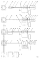
- the transport system comprises (FIG. 1) a Paper roll storage, in particular an intermediate storage 1 Recording of unpacked and provided with glue points, so for the roll change of prepared paper rolls from which a straight feeder track 2 over several turntables 3 leads, on each of which a loading track 4 branches off at right angles to a sliding platform 5 or a sliding lift of a roller stand 6 leads. If the sliding platform 5 in an acquisition position is located, the loading track 4 is aligned on the Feed side of the transfer table 5 with a track section 7 on the same. On the side facing away from the feed side includes one aligned with the loading track 5 Parking track 8 on.
- each of the loading tracks 4 there is a drive-less one Movable carriage 9a, which receive a paper roll 10 can and on another unpowered car 9b, the is usually parked on the parking track 8 is a Sleeve basket 11 used for receiving sleeves Paper rolls arranged.
- a vehicle 12 on the loading track 4 the Track section 7 and the parking track 8 can be moved, which is used both for the paper roll transport Carriage 9a as well as to the carriage carrying the sleeve basket 11 9b can be coupled.
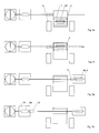
- the vehicle 12 has a frame 13 (FIGS. 2-4) the underside of which is a pair near both ends of wheels 14; 15 is stored.
- the pair of wheels 14 supporting axis is from an electric motor 16 Reduction gear 17 and an angular gear 18, the the underside of the frame 13 are suspended, driven.
- the electric motor 16 is a pantograph 19 and a Power section 20 supplied with a converter and controlled by a control part 21.
- a flag 22 is used Determining the position of the vehicle 12, as below will be explained in more detail.
- Around the middle of the Vehicle 12 is a pair of pressure wheels 23 in the frame stored, which in an unloaded basic position Wheels 14, 15 a little overhang, but against an elastic Restoring force can be pressed down.
- the electromagnetic clutch elements 24 each have (Fig. 3) a winding 26 which one protruding core 27 with a flat contact surface at the end surrounds. If necessary, it lies on an end face Housing of the coupled car 9 on.
- the button 25 includes a pin 28 which from the coupled carriage 9 against the Force of a compression spring 29 in a pushed back Position is held.
- the carriage 9 is formed in a manner known per se a chassis 30 that can be moved under the track and a recess 31 arranged above floor for receiving a Paper roll or a tube basket etc., which by means of a web is connected to the chassis 30.
- she can in this respect that described in EP-A-0 587 015 Cars match.
- the chassis 30 has at both ends to the longitudinal direction normal, from a ferromagnetic Material existing end wall 32 formed end faces on which the coupling elements 24 of the vehicle 12 can attack.
- the track is laid underground and includes (Fig. 4) in itself known two rails 33, which as opposing U-profiles are formed, which via support profiles and sleepers at the bottom of a trench are supported. It is potted with concrete and through on the rails 33 overlying cover plates 34 covered only a narrow one, centrally above the rails 25 leave lying gap 35 free.
- the inside of the bottom Flanges of the rails 33 form treads on which the Wheels 14, 15 run while the pressure wheels 23 are elastic press against the inside of the upper flanges so that the driven wheels 14 pressed against the treads and reliable frictional engagement with the rails 33 to have.
- the diameter of the wheels 14, 15 and the pressure wheels 23 are preferably the same and only slightly smaller than that Distance between the flanges of the rails 33.
- the control of the vehicles 12 can essentially be done by a stationary control unit can be done while that Control part 21 only performs elementary functions.
- the position of the vehicle is monitored by the marker 22 is detected by active sensors on the track. In In many cases it is sufficient if only the presence is present of vehicle 12 at certain stops and others Switching points is detected.
- the Position of the vehicle also constantly from the control unit be tracked, e.g. by calculating the route due to monitoring the wheel revolutions, the Detections only result in new calibrations of the position. In in this case a single sensor may be sufficient, which is passed regularly and then one at a time Triggers new calibration.
- an active sensor can also be provided be, while only markers are attached to the track, that are detected by the sensor.
- the flags can clearly marked or indistinguishable, only on certain points or at regular intervals to be appropriate.
- the detections can be made via the Conductor rails, via radio or a modulated one Infrared beam from the vehicle reported to the control unit become.
- Position monitoring is also conceivable a measuring beam in the track, which with a reflector on Vehicle interacts, but then the cross section of the Vehicle like the car the measuring beam between transmitter and Do not hinder reflector, moreover, requires Position monitoring on the track section 7 of the Transfer platform 5 some additional effort.
- the vehicle 12 may be in certain driving conditions 'hold', 'slow forward', 'fast forward', 'backward slow ',' backwards fast ', where' fast 'e.g. 0.2m / sec can correspond and 'slowly' about a fifth of it. It can in each case by the control unit by a specific switching command to a specific driving state to be switched in until it receives another Shift command remains. Or it can last so long in one State remain as there are periodic commands receives and fall into a basic state like 'hold' when stop the orders.
- the vehicle 12 can normally travel “quickly” be, but when passing a one to be approached Stop point upstream sensor switched to 'slow' so that as soon as the flag 22 is replaced by a another sensor is detected at the breakpoint and switchover to 'hold' is triggered, can stop almost immediately.
- the commands can in turn be sent from the control unit via the Busbars 36, via radio or a modulated Infrared beam are transmitted to the vehicle 12. If the vehicle carries an active sensor, certain can Transitions such as 'slow forward' - 'hold' or 'forward fast' - 'forward slow' also immediately be triggered by signals of the same when it is about a breakpoint or an upstream one Switching point responds.
- the vehicle can also be opened be energized in any other way. It can e.g. carry an energy store, e.g. a battery like that that no permanent energy transfer is required.
- an energy store e.g. a battery like that that no permanent energy transfer is required.
- the two-armed roller stand 6 carries one empty pod or an almost empty pod, i.e. an almost completely expired, separated residual roll and one Roll of paper that is being unwound (not shown).
- On the feed side of the transfer table 5 is near the Turntable 3 of the car 9a with the new, unpacked and with a glue paper roll 10 on a Waiting place of the loading track 4 parked and that Vehicle 12 at a stopping point next to the transfer platform 5, which is in the takeover position.
- the carriage 9b with the sleeve basket 11 stands on the parking track 8.
- the carriage 9b stands with the sleeve basket 11 centered on it Transfer platform (Fig. 5c). Because the track section 7 is too short is to fully accommodate the vehicle 12, the Coupling elements switched off and the vehicle 12 'backwards fast' a short distance to a stop the loading track 4 so that it from Track section 7 is free (Fig. 5d). Now the Sliding platform 5 moved against the roller stand 6 until the Sleeve basket 11 is under the sleeve, which is now from the cones the roll stand 6 is released and in the sleeve basket 11 falls (sleeve 38, Fig. 5e). The sliding platform 5 is in the Move back takeover position (Fig. 5f) and then the Carriage 9b from vehicle 12 back onto parking track 8 pushed (Fig. 5g).
- Vehicle 12 now travels to feed paper roll 10 again 'backwards fast' to a switching point shortly before Stop and then with the coupling elements switched on 'backwards slow' until it hits car 9a, coupled to the same and switched to 'hold' (Fig. 5h).
- Switched to 'fast forward' that drives Vehicle 12 now with the car 9a on the Loading track 4 back to the transfer platform 5 where it is again passes a switching point and, on 'forward slow 'switched to a breakpoint at which the Paper roll 10 is centered on the transfer table 5 (Fig. 5i). If the paper roll 10 is not always exactly centered lies on the carriage 9a or different roll widths are possible, the passage of their front edge or the Front and rear edge through a light barrier detected and another after reaching the breakpoint Compensating shift are carried out.
- the vehicle 12 is then uncoupled and connected to one Stop point on the parking track 8, where it from Track section 7 is free (Fig. 5j). Then will the sliding platform 5 with the carriage 9a towards the roller stand 6 moved and the paper roll 10 between the by the Ejection of the sleeve-free cones clamped (Fig. 5k) and lifted off the carriage 9a. The sliding platform 5 with the car 9a is then moved back into the take-over position (Fig. 51). The vehicle 12 now drives with the switch on Coupling elements 24 'slowly backwards' on the Track section 7 of the scissor lift 5 until it reaches the carriage 9a pushes and couples (Fig. 5m).
- the vehicle drives 12 'backwards fast' over the track section 7 and that Loading track 4 to the waiting area upstream switching point and 'reverse slow' until it reached a stopping point such that the car at the same time 9a occupies the waiting area (FIG. 5n).
- the coupling elements are then turned off and the vehicle 12 on retract its stop next to the transfer platform 5 (Fig. 50). So the initial state is reached again, with the difference that the carriage 9a does not have a paper roll wearing.
- the carriage 9a can then be moved manually and by one wagons loaded with a roll of paper are replaced, which is also pushed manually into the waiting area. If the transport system is equipped accordingly, can the car 9a but also in the waiting area with a new one Paper roll to be loaded, for example by means of a Crane system is brought directly from the interim storage facility.
- the feed to the loading tracks can be done instead of the Access tracks and the turntables also through one sliding platform-like transfer carriage are made, the is movable parallel to the row of roller stands and one across, i.e. parallel to the loading tracks aligned track section at the end of the Holding a trolley at a loading position Coupling element and a sensor are provided, which of the vehicle.
- the one in the loading position on the In this case, the moving carriage will stand on Interim storage using a crane or telescopic arms loaded and then move the transfer carriage until it Track section with a selected loading track aligns, whereupon the vehicle on the track section drives, hitched to the car and it over the Loading track pulls onto the transfer platform.
Landscapes
- Engineering & Computer Science (AREA)
- Mechanical Engineering (AREA)
- Replacement Of Web Rolls (AREA)
- Platform Screen Doors And Railroad Systems (AREA)
- Control Of Position, Course, Altitude, Or Attitude Of Moving Bodies (AREA)
- Handcart (AREA)
Abstract
Description
- Fig. 1
- eine Draufsicht auf eine erfindungsgemässe Transportanlage,
- Fig. 2
- eine Seitenansicht eines erfindungsgemässen Fahrzeugs,
- Fig. 3
- einen Längsschnitt durch einen Endabschnitt eines Fahrzeugs und einen anstossenden Endabschnitt eines an dasselbe gekuppelten Wagens,
- Fig. 4
- eine Vorderansicht des Fahrzeugs nach Fig. 2 sowie einen Schnitt durch ein Geleise, auf dem dasselbe verfahrbar ist und
- Fig. 5a-o
- die Zufuhr einer neuen Papierrolle zu einem Rollenständer mittels der erfindungsgemässen Transportanlage einschliesslich der Entfernung einer Hülse oder Restrolle, die gegen sie ausgewechselt wird. Dabei zeigt
- Fig. 5a
- einen Teil der erfindungsgemässen Transportanlage nach Fig. 1 zu Beginn der Rollenzufuhr,
- Fig. 5b
- den Anlagenteil von Fig. 5a nach einem ersten Schritt der Rollenzufuhr,
- Fig. 5c
- den Anlagenteil von Fig. 5a nach einem zweiten Schritt der Rollenzufuhr,
- Fig. 5d
- den Anlagenteil von Fig. 5a nach einem dritten Schritt der Rollenzufuhr,
- Fig. 5e
- den Anlagenteil von Fig. 5a nach einem vierten Schritt der Rollenzufuhr,
- Fig. 5f
- den Anlagenteil von Fig. 5a nach einem fünften Schritt der Rollenzufuhr,
- Fig. 5g
- den Anlagenteil von Fig. 5a nach einem sechsten Schritt der Rollenzufuhr,
- Fig. 5h
- den Anlagenteil von Fig. 5a nach einem siebenten Schritt der Rollenzufuhr,
- Fig. 5i
- den Anlagenteil von Fig. 5a nach einem achten Schritt der Rollenzufuhr,
- Fig. 5j
- den Anlagenteil von Fig. 5a nach einem neunten Schritt der Rollenzufuhr,
- Fig. 5k
- den Anlagenteil von Fig. 5a nach einem zehnten Schritt der Rollenzufuhr,
- Fig. 5l
- den Anlagenteil von Fig. 5a nach einem elften Schritt der Rollenzufuhr,
- Fig. 5m
- den Anlagenteil von Fig. 5a nach einem zwölften Schritt der Rollenzufuhr,
- Fig. 5n
- den Anlagenteil von Fig. 5a nach einem dreizehnten Schritt der Rollenzufuhr und
- Fig. 5o
- den Anlagenteil von Fig. 5a am Ende der Rollenzufuhr.
- 1
- Zwischenlager
- 2
- Zubringgeleise
- 3
- Drehscheibe
- 4
- Beschickungsgeleise
- 5
- Schiebebühne
- 6
- Rollenständer
- 7
- Geleiseabschnitt
- 8
- Abstellgeleise
- 9, 9a,b
- Wagen
- 10
- Papierrolle
- 11
- Hülsenkorb
- 12
- Fahrzeug
- 13
- Rahmen
- 14, 15
- Räder
- 16
- Elektromotor
- 17
- Untersetzungsgetriebe
- 18
- Winkelgetriebe
- 19
- Stromabnehmer
- 20
- Leistungsteil
- 21
- Steuerteil
- 22
- Merker
- 23
- Anpressräder
- 24
- Kupplungselemente
- 25
- Taster
- 26
- Wicklung
- 27
- Kern
- 28
- Stift
- 29
- Druckfeder
- 30
- Fahrgestell
- 31
- Mulde
- 32
- Stirnwand
- 33
- Schienen
- 34
- Abdeckbleche
- 35
- Spalt
- 36
- Stromschienen
- 37
- Kabelkanal
- 38
- Hülse
Claims (15)
- Transportanlage zur Zuführung von Papierrollen zu mindestens einem Rollenständer (6), mit mindestens einer Schiebühne (5) mit einem Geleiseabschnitt (7) und einem von einer Zufuhrseite zur Schiebebühne (5) führenden Beschickungsgeleise (4), mit welchem der Geleiseabschnitt (7) fluchtet, wenn sich die Schiebebühne (5) in einer Uebernahmeposition befindet sowie mit mindestens einem antriebslosen Wagen (9a) zur Aufnahme einer Papierrolle (10), dadurch gekennzeichnet, dass sie mindestens ein angetriebenes Fahrzeug (12) umfasst, welches auf dem Beschickungsgeleise (4) und dem Geleiseabschnitt (7) verfahrbar ist und das Fahrzeug (12) und der Wagen (9a) jeweils mindestens eine Kupplungseinrichtung aufweisen, mittels welcher das Fahrzeug (12) an den Wagen (9a) ankuppelbar ist.
- Transportanlage nach Anspruch 1, dadurch gekennzeichnet, dass das Beschickungsgeleise (4) unterflur angeordnet ist und das Fahrzeug (12) unterflur auf demselben verfahrbar ist.
- Transportanlage nach Anspruch 1 oder 2, dadurch gekennzeichnet, dass der Geleiseabschnitt (7) durch die Schiebebühne (5) durchgehend ausgebildet ist und auf der der Zufuhrseite abgewandten Seite an die Schiebebühne (5) ein Abstellgeleise (8) anschliesst, das mit dem Beschickungsgeleise (4) fluchtet.
- Transportanlage nach einem der Ansprüche 1 bis 3, dadurch gekennzeichnet, dass sie mehrere Schiebebühnen (5) und parallele Beschickungsgeleise (4) umfasst sowie ein von einem Papierrollenlager zu den Beschickungsgeleisen (4) führendes Zubringgeleise (2), mit welchem die Beschickungsgeleise (4) jeweils durch eine Drehscheibe (3) verbunden sind.
- Verfahren zum Betrieb einer Transportanlage nach einem der Ansprüche 1 bis 4, bei welchem ein mit einer Papierrolle (10) beladener Wagen (9a) von einem Warteplatz über das Beschickungsgeleise (4) auf die Schiebebühne (5), welche sich in der Uebernahmeposition befindet, verfahren und anschliessend zur Uebergabe der Papierrolle (10) an den Rollenständer (6) die Schiebebühne (5) mit dem Wagen (9a) unter den Rollenständer (6) verschoben und die Papierrolle (10) vom Wagen (9a) abgehoben wird und dann die Schiebebühne (5) wieder in die Uebernahmeposition verschoben wird, worauf der Wagen (9a) zurück auf den Warteplatz verfahren wird, dadurch gekennzeichnet, dass zum Verfahren desselben auf die Schiebebühne (5) am derselben zugewandten Ende des Wagens (9a) ein angetriebenes Fahrzeug (12) angekuppelt wird, welches daraufhin den Wagen (9a) auf die Schiebebühne (5) zieht und nach Uebergabe der Papierrolle (10) an den Rollenständer (6) zurück auf den Warteplatz schiebt.
- Verfahren nach Anspruch 5 zum Betrieb einer Transportanlage nach Anspruch 3 oder 4, dadurch gekennzeichnet, dass vor der Uebergabe der Papierrolle (10) an den Rollenständer (6) das Fahrzeug (12) vom Wagen (9a) abgekuppelt und auf das Abstellgeleise (8) verfahren wird.
- Verfahren nach Anspruch 5 zum Betrieb einer Transportanlage nach Anspruch 3 oder 4 oder nach Anspruch 6, dadurch gekennzeichnet, dass vor dem Verfahren des Wagens (9a) vom Warteplatz auf die Schiebebühne (5) das Fahrzeug (12) an einen auf dem Abstellgeleise (8) stehenden mit einem Hülsenkorb (11) beladenen Wagen (9b) angekuppelt wird, welches daraufhin denselben auf die Schiebebühne (5), welche sich in der Uebernahmeposition befindet, zieht und anschliessend zur Uebernahme einer Hülse (38) vom Rollenständer (6) die Schiebebühne (5) mit dem Wagen (9b) unter den Rollenständer (6) verschoben und die Hülse (38) in den Hülsenkorb (11) abgeworfen wird und die Schiebebühne (5) wieder in die Uebernahmeposition verschoben wird, worauf der Wagen (9b) durch das Fahrzeug (12) zurück auf das Abstellgeleise (8) geschoben und das Fahrzeug (12) abgekuppelt wird.
- Verfahren nach Anspruch 7, dadurch gekennzeichnet, dass vor der Uebernahme der Hülse (38) vom Rollenständer (6) das Fahrzeug (12) vom Wagen (9b) abgekuppelt und auf das Beschickungsgeleise (4) verfahren wird.
- Fahrzeug für eine Transportanlage nach einem der Ansprüche 1 bis 4, mit mindestens zwei Paaren von Rädern (14, 15), dadurch gekennzeichnet, dass mindestens ein Paar von Rädern (14) zum Verfahren des Fahrzeugs (12) antreibbar ist und mindestens eine Kupplungseinrichtung vorgesehen ist zur lösbaren Ankupplung des Fahrzeugs (12) an einen Wagen.
- Fahrzeug nach Anspruch 9, dadurch gekennzeichnet, dass die mindestens eine Kupplungseinrichtung als ein- und ausschaltbares elektromagnetisches Kupplungselement (24) ausgebildet ist.
- Fahrzeug nach Anspruch 9 oder 10, dadurch gekennzeichnet, dass die mindestens eine Kupplungseinrichtung (24) pufferartig ausgebildet ist.
- Fahrzeug nach einem der Ansprüche 9 bis 11, dadurch gekennzeichnet, dass es an jedem Ende eine Kupplungseinrichtung aufweist.
- Fahrzeug nach einem der Ansprüche 9 bis 12, dadurch gekennzeichnet, dass jeder Kupplungseinrichtung ein Sensor zugeordnet ist zur Feststellung eines allfälligen angekuppelten Wagens (9).
- Fahrzeug nach Anspruch 13, dadurch gekennzeichnet, dass der Sensor als Taster (25) ausgebildet ist.
- Fahrzeug nach einem der Ansprüche 9 bis 14, dadurch gekennzeichnet, dass es mindestens ein Paar von Anpressrädern (23) aufweist, das im unbelasteten Zustand über die Paare von Rädern (14, 15) hinausragt und gegen eine Rückstellkraft nach unten verschiebbar ist.
Priority Applications (11)
| Application Number | Priority Date | Filing Date | Title |
|---|---|---|---|
| AT02405817T ATE337247T1 (de) | 2002-09-23 | 2002-09-23 | Transportanlage für papierrollen, verfahren zu ihrem betrieb sowie fahrzeug |
| EP02405817A EP1400472B1 (de) | 2002-09-23 | 2002-09-23 | Transportanlage für Papierrollen, Verfahren zu ihrem Betrieb sowie Fahrzeug |
| DE50207942T DE50207942D1 (de) | 2002-09-23 | 2002-09-23 | Transportanlage für Papierrollen, Verfahren zu ihrem Betrieb sowie Fahrzeug |
| ES02405817T ES2269642T3 (es) | 2002-09-23 | 2002-09-23 | Instalacion transportadora de bobinas de papel, procedimiento para su puesta en funcionamiento, asi como vehiculo. |
| CA002428878A CA2428878A1 (en) | 2002-09-23 | 2003-05-16 | Transport installation for paper reels, method for its operation and vehicle |
| US10/441,108 US20040056140A1 (en) | 2002-09-23 | 2003-05-20 | Transport installation for paper reels, method for its operation and vehicle |
| MYPI20031909A MY135546A (en) | 2002-09-23 | 2003-05-23 | Transport installation for paper reels and method for its operation |
| KR1020030033527A KR100541293B1 (ko) | 2002-09-23 | 2003-05-27 | 페이퍼 릴용 이송 설비, 그 작동 방법 및 차량 |
| JP2003156446A JP2004115000A (ja) | 2002-09-23 | 2003-06-02 | ペーパーリールの搬送システム、搬送方法、および運搬装置 |
| TW092117405A TWI226305B (en) | 2002-09-23 | 2003-06-26 | Transport installation for paper reels, method for its operation and vehicle |
| CNB03153466XA CN100347060C (zh) | 2002-09-23 | 2003-08-13 | 纸卷的输送装置、其操作方法和运载工具 |
Applications Claiming Priority (1)
| Application Number | Priority Date | Filing Date | Title |
|---|---|---|---|
| EP02405817A EP1400472B1 (de) | 2002-09-23 | 2002-09-23 | Transportanlage für Papierrollen, Verfahren zu ihrem Betrieb sowie Fahrzeug |
Publications (2)
| Publication Number | Publication Date |
|---|---|
| EP1400472A1 true EP1400472A1 (de) | 2004-03-24 |
| EP1400472B1 EP1400472B1 (de) | 2006-08-23 |
Family
ID=31897007
Family Applications (1)
| Application Number | Title | Priority Date | Filing Date |
|---|---|---|---|
| EP02405817A Expired - Lifetime EP1400472B1 (de) | 2002-09-23 | 2002-09-23 | Transportanlage für Papierrollen, Verfahren zu ihrem Betrieb sowie Fahrzeug |
Country Status (11)
| Country | Link |
|---|---|
| US (1) | US20040056140A1 (de) |
| EP (1) | EP1400472B1 (de) |
| JP (1) | JP2004115000A (de) |
| KR (1) | KR100541293B1 (de) |
| CN (1) | CN100347060C (de) |
| AT (1) | ATE337247T1 (de) |
| CA (1) | CA2428878A1 (de) |
| DE (1) | DE50207942D1 (de) |
| ES (1) | ES2269642T3 (de) |
| MY (1) | MY135546A (de) |
| TW (1) | TWI226305B (de) |
Cited By (6)
| Publication number | Priority date | Publication date | Assignee | Title |
|---|---|---|---|---|
| EP2006228A2 (de) | 2007-06-21 | 2008-12-24 | WIFAG Maschinenfabrik AG | Rollenwechselvorrichtung mit Transportwagensystem |
| EP2030927A3 (de) * | 2007-08-31 | 2009-11-04 | Voith Patent GmbH | Vorrichtung zum Bewegen einer auf einer Maschine zur Herstellung von Faserstoffbahnen hergestellten Abwickelrolle |
| EP2119654A1 (de) * | 2008-05-13 | 2009-11-18 | Goss Contiweb B.V. | Zufuhrstation für eine Druckpresse, entsprechende Druckpresse und Verwendung |
| WO2011095696A1 (en) * | 2010-02-03 | 2011-08-11 | Metso Paper, Inc. | Arrangement for controlling pressure medium |
| DE102011008583A1 (de) * | 2011-01-14 | 2012-07-19 | Manroland Ag | Beladungsanordnung für einen Rollenwechsler einer Rollendruckmaschine und Verfahren zum Betreiben derselben |
| CN102662401A (zh) * | 2012-05-25 | 2012-09-12 | 上海电力学院 | 一种基于电磁感应循迹的导航系统 |
Families Citing this family (17)
| Publication number | Priority date | Publication date | Assignee | Title |
|---|---|---|---|---|
| DE102008009916A1 (de) * | 2008-02-15 | 2009-11-12 | Sms Siemag Aktiengesellschaft | Walzanlage zum Walzen von bandförmigem Walzgut |
| US8047756B2 (en) * | 2008-04-04 | 2011-11-01 | Savant Automation, Inc. | Automatic load transfer device and method for automated material handling systems |
| DE102008049180A1 (de) * | 2008-09-26 | 2010-04-01 | Sms Siemag Aktiengesellschaft | Walzanlage zum Walzen von bandförmigem Walzgut |
| US10266361B2 (en) | 2011-08-31 | 2019-04-23 | Pregis Intellipack Llc | Spindle mechanism for protective packaging device |
| DE102015208122A1 (de) * | 2015-04-30 | 2016-11-03 | Krones Aktiengesellschaft | Verfahren und Vorrichtung zur Zuförderung, Bereitstellung und zum Austausch von Rollen mit Verpackungsmaterial in einer Verpackungsmaschine |
| CN105329658B (zh) * | 2015-09-30 | 2017-10-31 | 金东纸业(江苏)股份有限公司 | 一种自动垫纸装置 |
| CN106938793B (zh) * | 2016-01-04 | 2024-03-19 | 佛山市宝索机械制造有限公司 | 高效的纸卷分配装置 |
| CN108162984B (zh) * | 2017-12-08 | 2023-09-05 | 杭州久智自动化技术有限公司 | 轨道网的基本运行子段 |
| CN108608682A (zh) * | 2018-03-28 | 2018-10-02 | 河南省新斗彩印刷有限公司 | 瓦楞纸板生产线全自动供纸系统 |
| CN108861635A (zh) * | 2018-05-11 | 2018-11-23 | 河南省新斗彩印刷有限公司 | 瓦楞纸板生产线全自动供纸系统的智能控制方法 |
| DE102019201595A1 (de) * | 2019-02-07 | 2020-08-13 | Bhs Intralogistics Gmbh | Übergabesystem |
| CN110001503B (zh) * | 2019-04-25 | 2024-07-16 | 华晓精密工业(苏州)有限公司 | 装夹机构以及搬运装置 |
| CN112551080B (zh) * | 2020-12-24 | 2026-03-20 | 上海寰宇物流科技有限公司 | 一种冷藏集装箱的前后框自动上下料转运系统 |
| CN114538009B (zh) * | 2022-03-25 | 2024-05-31 | 湖南嘉龙环保包装有限公司 | 一种自动接纸用材料输送装置 |
| CN116513826A (zh) * | 2023-05-23 | 2023-08-01 | 无锡理奇智能装备有限公司 | 一种产线配料计量系统 |
| CN116873427B (zh) * | 2023-07-27 | 2025-12-30 | 江苏卫生健康职业学院 | 一种医药用自动存取储存柜 |
| WO2025186749A1 (en) * | 2024-03-07 | 2025-09-12 | Automha S.P.A. | Recovery vehicle for a load-handling vehicle in an automated warehouse, vehicle recovery method |
Citations (6)
| Publication number | Priority date | Publication date | Assignee | Title |
|---|---|---|---|---|
| DE2334141A1 (de) * | 1973-07-05 | 1975-01-23 | Griese Klaus P | Vorrichtung zur ueberfuehrung von brennoder trockenwagen in anlagen der keramischen industrie |
| DE2554962A1 (de) * | 1975-12-06 | 1977-06-16 | Hauhinco Maschf | Rangieranlage |
| GB2181117A (en) * | 1985-09-06 | 1987-04-15 | Wifag Maschf | Method for handling reels in a web-fed rotary printing press |
| US5261331A (en) * | 1989-12-21 | 1993-11-16 | Harsco Corporation | Propulsion device for a train intended for renewal of railway tracks utilizing rail grippers to supply propulsion thrust |
| DE19860475A1 (de) * | 1998-12-28 | 2000-07-06 | Koenig & Bauer Ag | Einrichtung zum Aufnehmen und Transportieren von Papierbahn-Restrollen für eine Rollenrotationsdruckmaschine |
| US6155516A (en) * | 1996-09-16 | 2000-12-05 | Koenig & Bauer Aktiengesellschaft | Method for transporting rolls to a roll changer |
Family Cites Families (9)
| Publication number | Priority date | Publication date | Assignee | Title |
|---|---|---|---|---|
| US3556011A (en) * | 1968-07-11 | 1971-01-19 | Whiting Corp | Railway car handling mechanism |
| FR2137081B1 (de) * | 1971-05-12 | 1976-03-19 | Mills Const Sa | |
| GB2162137B (en) * | 1984-06-18 | 1988-07-20 | Daifuku Kk | Conveying system |
| FR2611557B1 (fr) * | 1987-03-04 | 1994-02-25 | Teissier Etienne | Machine de transfert libre a chariots independants et motorises |
| FI81309C (fi) * | 1989-01-04 | 1990-10-10 | Pesmel Insinoeoeritoimisto | Transportvagn. |
| US5076751A (en) * | 1990-03-23 | 1991-12-31 | Jervis B. Webb Company | Reelroom newsprint roll handling apparatus and method |
| US5115745A (en) * | 1991-02-22 | 1992-05-26 | Jervis B. Webb Company | Power transmitting assembly for reciprocatably moving a shuttle cart |
| US5979334A (en) * | 1995-06-07 | 1999-11-09 | Autran Corp. | System for automated transport of automobile platforms, passenger cabins and other loads |
| US6360670B1 (en) * | 1999-10-01 | 2002-03-26 | Flight Rail Corporation | Magnetically coupled transportation module |
-
2002
- 2002-09-23 DE DE50207942T patent/DE50207942D1/de not_active Expired - Fee Related
- 2002-09-23 AT AT02405817T patent/ATE337247T1/de not_active IP Right Cessation
- 2002-09-23 ES ES02405817T patent/ES2269642T3/es not_active Expired - Lifetime
- 2002-09-23 EP EP02405817A patent/EP1400472B1/de not_active Expired - Lifetime
-
2003
- 2003-05-16 CA CA002428878A patent/CA2428878A1/en not_active Abandoned
- 2003-05-20 US US10/441,108 patent/US20040056140A1/en not_active Abandoned
- 2003-05-23 MY MYPI20031909A patent/MY135546A/en unknown
- 2003-05-27 KR KR1020030033527A patent/KR100541293B1/ko not_active Expired - Fee Related
- 2003-06-02 JP JP2003156446A patent/JP2004115000A/ja active Pending
- 2003-06-26 TW TW092117405A patent/TWI226305B/zh not_active IP Right Cessation
- 2003-08-13 CN CNB03153466XA patent/CN100347060C/zh not_active Expired - Fee Related
Patent Citations (6)
| Publication number | Priority date | Publication date | Assignee | Title |
|---|---|---|---|---|
| DE2334141A1 (de) * | 1973-07-05 | 1975-01-23 | Griese Klaus P | Vorrichtung zur ueberfuehrung von brennoder trockenwagen in anlagen der keramischen industrie |
| DE2554962A1 (de) * | 1975-12-06 | 1977-06-16 | Hauhinco Maschf | Rangieranlage |
| GB2181117A (en) * | 1985-09-06 | 1987-04-15 | Wifag Maschf | Method for handling reels in a web-fed rotary printing press |
| US5261331A (en) * | 1989-12-21 | 1993-11-16 | Harsco Corporation | Propulsion device for a train intended for renewal of railway tracks utilizing rail grippers to supply propulsion thrust |
| US6155516A (en) * | 1996-09-16 | 2000-12-05 | Koenig & Bauer Aktiengesellschaft | Method for transporting rolls to a roll changer |
| DE19860475A1 (de) * | 1998-12-28 | 2000-07-06 | Koenig & Bauer Ag | Einrichtung zum Aufnehmen und Transportieren von Papierbahn-Restrollen für eine Rollenrotationsdruckmaschine |
Cited By (9)
| Publication number | Priority date | Publication date | Assignee | Title |
|---|---|---|---|---|
| EP2006228A2 (de) | 2007-06-21 | 2008-12-24 | WIFAG Maschinenfabrik AG | Rollenwechselvorrichtung mit Transportwagensystem |
| EP2006228A3 (de) * | 2007-06-21 | 2009-10-21 | WIFAG Maschinenfabrik AG | Rollenwechselvorrichtung mit Transportwagensystem |
| EP2030927A3 (de) * | 2007-08-31 | 2009-11-04 | Voith Patent GmbH | Vorrichtung zum Bewegen einer auf einer Maschine zur Herstellung von Faserstoffbahnen hergestellten Abwickelrolle |
| EP2119654A1 (de) * | 2008-05-13 | 2009-11-18 | Goss Contiweb B.V. | Zufuhrstation für eine Druckpresse, entsprechende Druckpresse und Verwendung |
| US8387908B2 (en) | 2008-05-13 | 2013-03-05 | Goss Contiweb B.V. | Feeding station for a printing press, corresponding printing press and method |
| WO2011095696A1 (en) * | 2010-02-03 | 2011-08-11 | Metso Paper, Inc. | Arrangement for controlling pressure medium |
| DE102011008583A1 (de) * | 2011-01-14 | 2012-07-19 | Manroland Ag | Beladungsanordnung für einen Rollenwechsler einer Rollendruckmaschine und Verfahren zum Betreiben derselben |
| CN102662401A (zh) * | 2012-05-25 | 2012-09-12 | 上海电力学院 | 一种基于电磁感应循迹的导航系统 |
| CN102662401B (zh) * | 2012-05-25 | 2014-04-16 | 上海电力学院 | 一种基于电磁感应循迹的导航系统 |
Also Published As
| Publication number | Publication date |
|---|---|
| CN1485259A (zh) | 2004-03-31 |
| KR20040026592A (ko) | 2004-03-31 |
| TW200404728A (en) | 2004-04-01 |
| MY135546A (en) | 2008-05-30 |
| TWI226305B (en) | 2005-01-11 |
| US20040056140A1 (en) | 2004-03-25 |
| JP2004115000A (ja) | 2004-04-15 |
| ES2269642T3 (es) | 2007-04-01 |
| CN100347060C (zh) | 2007-11-07 |
| KR100541293B1 (ko) | 2006-01-10 |
| DE50207942D1 (de) | 2006-10-05 |
| ATE337247T1 (de) | 2006-09-15 |
| EP1400472B1 (de) | 2006-08-23 |
| CA2428878A1 (en) | 2004-03-23 |
Similar Documents
| Publication | Publication Date | Title |
|---|---|---|
| EP1400472B1 (de) | Transportanlage für Papierrollen, Verfahren zu ihrem Betrieb sowie Fahrzeug | |
| EP3490843B1 (de) | Routenzuganhänger und transportsystem sowie transportverfahren | |
| DE2621021C2 (de) | ||
| EP3388295B1 (de) | Verfahren zum betreiben eines transportsystems sowie entsprechendes transportsystem | |
| EP2558384A1 (de) | Lager- und transportsystem für transportbehälter | |
| EP1718552B1 (de) | Vorrichtung zum transport von materialrollen | |
| EP1384814B1 (de) | Speicherwagen mit einer Tasteinrichtung | |
| EP2151402A2 (de) | Logistiksystem | |
| DE60117057T2 (de) | Punkt-zu-punkt-transportsystem | |
| EP1422169B1 (de) | Lagersystem mit schienengebundenen Fahrzeugen zur Aufnahme und Abgabe von Lagergut | |
| DE2130147A1 (de) | Foerdersystem | |
| WO2019197089A1 (de) | Materialrollen-transportwagen | |
| EP4373766A1 (de) | Regalbediensystem, hochregallager, einlagerungsverfahren und auslagerungsverfahren | |
| CH641516A5 (de) | Einrichtung zum betrieb von transportfahrzeugen auf einem gleisfahrzeugverband. | |
| DE19711462A1 (de) | Güterverkehrs- und verteilsystem | |
| EP0360053B1 (de) | Vorrichtung zum Wechseln leerer gegen volle Kannen an einem Spinnautomaten | |
| EP3795419B1 (de) | Routenzuganhänger und routenzug | |
| DE102012216429B4 (de) | Fahrerloses Flurfördersystem | |
| EP3774319A1 (de) | Wellpappeanlage | |
| EP2113478A1 (de) | Vorrichtung zum Transport von Materialrollen | |
| DE69011621T2 (de) | Einrichtung und Verfahren zum Handhaben von Behältern, die auf Eisenbahnwagen transportiert werden. | |
| EP3976448A1 (de) | System umfassend einen routenzug mit mindestens einen routenzuganhänger und mindestens einen von dem routenzuganhänger aufnehmbaren wagen | |
| EP0769407B1 (de) | Mitfahrende Fahrleitung | |
| DE202025101731U1 (de) | Transportsystem für den innerbetrieblichen Materialtransport umfassend einen Routenzug | |
| DE202012004311U1 (de) | Vorrichtung für das bündige Umsetzen großflächiger Plattenunterschiedlicher Bauart auf ein Transportfahrzeug |
Legal Events
| Date | Code | Title | Description |
|---|---|---|---|
| PUAI | Public reference made under article 153(3) epc to a published international application that has entered the european phase |
Free format text: ORIGINAL CODE: 0009012 |
|
| 17P | Request for examination filed |
Effective date: 20030405 |
|
| AK | Designated contracting states |
Kind code of ref document: A1 Designated state(s): AT BE BG CH CY CZ DE DK EE ES FI FR GB GR IE IT LI LU MC NL PT SE SK TR |
|
| AX | Request for extension of the european patent |
Extension state: AL LT LV MK RO SI |
|
| AKX | Designation fees paid |
Designated state(s): AT BE BG CH CY CZ DE DK EE ES FI FR GB GR IE IT LI LU MC NL PT SE SK TR |
|
| GRAP | Despatch of communication of intention to grant a patent |
Free format text: ORIGINAL CODE: EPIDOSNIGR1 |
|
| GRAS | Grant fee paid |
Free format text: ORIGINAL CODE: EPIDOSNIGR3 |
|
| GRAA | (expected) grant |
Free format text: ORIGINAL CODE: 0009210 |
|
| AK | Designated contracting states |
Kind code of ref document: B1 Designated state(s): AT BE BG CH CY CZ DE DK EE ES FI FR GB GR IE IT LI LU MC NL PT SE SK TR |
|
| PG25 | Lapsed in a contracting state [announced via postgrant information from national office to epo] |
Ref country code: IE Free format text: LAPSE BECAUSE OF FAILURE TO SUBMIT A TRANSLATION OF THE DESCRIPTION OR TO PAY THE FEE WITHIN THE PRESCRIBED TIME-LIMIT Effective date: 20060823 Ref country code: SK Free format text: LAPSE BECAUSE OF FAILURE TO SUBMIT A TRANSLATION OF THE DESCRIPTION OR TO PAY THE FEE WITHIN THE PRESCRIBED TIME-LIMIT Effective date: 20060823 Ref country code: CZ Free format text: LAPSE BECAUSE OF FAILURE TO SUBMIT A TRANSLATION OF THE DESCRIPTION OR TO PAY THE FEE WITHIN THE PRESCRIBED TIME-LIMIT Effective date: 20060823 Ref country code: FI Free format text: LAPSE BECAUSE OF FAILURE TO SUBMIT A TRANSLATION OF THE DESCRIPTION OR TO PAY THE FEE WITHIN THE PRESCRIBED TIME-LIMIT Effective date: 20060823 |
|
| REG | Reference to a national code |
Ref country code: GB Ref legal event code: FG4D Free format text: NOT ENGLISH |
|
| REG | Reference to a national code |
Ref country code: CH Ref legal event code: EP |
|
| REG | Reference to a national code |
Ref country code: IE Ref legal event code: FG4D Free format text: LANGUAGE OF EP DOCUMENT: GERMAN |
|
| PG25 | Lapsed in a contracting state [announced via postgrant information from national office to epo] |
Ref country code: LI Free format text: LAPSE BECAUSE OF NON-PAYMENT OF DUE FEES Effective date: 20060930 Ref country code: CH Free format text: LAPSE BECAUSE OF NON-PAYMENT OF DUE FEES Effective date: 20060930 Ref country code: MC Free format text: LAPSE BECAUSE OF NON-PAYMENT OF DUE FEES Effective date: 20060930 |
|
| REF | Corresponds to: |
Ref document number: 50207942 Country of ref document: DE Date of ref document: 20061005 Kind code of ref document: P |
|
| PG25 | Lapsed in a contracting state [announced via postgrant information from national office to epo] |
Ref country code: DK Free format text: LAPSE BECAUSE OF FAILURE TO SUBMIT A TRANSLATION OF THE DESCRIPTION OR TO PAY THE FEE WITHIN THE PRESCRIBED TIME-LIMIT Effective date: 20061123 Ref country code: BG Free format text: LAPSE BECAUSE OF FAILURE TO SUBMIT A TRANSLATION OF THE DESCRIPTION OR TO PAY THE FEE WITHIN THE PRESCRIBED TIME-LIMIT Effective date: 20061123 Ref country code: SE Free format text: LAPSE BECAUSE OF FAILURE TO SUBMIT A TRANSLATION OF THE DESCRIPTION OR TO PAY THE FEE WITHIN THE PRESCRIBED TIME-LIMIT Effective date: 20061123 |
|
| GBT | Gb: translation of ep patent filed (gb section 77(6)(a)/1977) |
Effective date: 20061113 |
|
| PG25 | Lapsed in a contracting state [announced via postgrant information from national office to epo] |
Ref country code: PT Free format text: LAPSE BECAUSE OF FAILURE TO SUBMIT A TRANSLATION OF THE DESCRIPTION OR TO PAY THE FEE WITHIN THE PRESCRIBED TIME-LIMIT Effective date: 20070125 |
|
| REG | Reference to a national code |
Ref country code: IE Ref legal event code: FD4D |
|
| ET | Fr: translation filed | ||
| REG | Reference to a national code |
Ref country code: ES Ref legal event code: FG2A Ref document number: 2269642 Country of ref document: ES Kind code of ref document: T3 |
|
| REG | Reference to a national code |
Ref country code: CH Ref legal event code: PL |
|
| PLBE | No opposition filed within time limit |
Free format text: ORIGINAL CODE: 0009261 |
|
| STAA | Information on the status of an ep patent application or granted ep patent |
Free format text: STATUS: NO OPPOSITION FILED WITHIN TIME LIMIT |
|
| 26N | No opposition filed |
Effective date: 20070524 |
|
| PGFP | Annual fee paid to national office [announced via postgrant information from national office to epo] |
Ref country code: DE Payment date: 20070920 Year of fee payment: 6 |
|
| PGFP | Annual fee paid to national office [announced via postgrant information from national office to epo] |
Ref country code: AT Payment date: 20070912 Year of fee payment: 6 |
|
| PGFP | Annual fee paid to national office [announced via postgrant information from national office to epo] |
Ref country code: GB Payment date: 20070919 Year of fee payment: 6 |
|
| PGFP | Annual fee paid to national office [announced via postgrant information from national office to epo] |
Ref country code: ES Payment date: 20071024 Year of fee payment: 6 Ref country code: IT Payment date: 20070927 Year of fee payment: 6 Ref country code: NL Payment date: 20070903 Year of fee payment: 6 |
|
| PGFP | Annual fee paid to national office [announced via postgrant information from national office to epo] |
Ref country code: BE Payment date: 20071121 Year of fee payment: 6 |
|
| PG25 | Lapsed in a contracting state [announced via postgrant information from national office to epo] |
Ref country code: GR Free format text: LAPSE BECAUSE OF FAILURE TO SUBMIT A TRANSLATION OF THE DESCRIPTION OR TO PAY THE FEE WITHIN THE PRESCRIBED TIME-LIMIT Effective date: 20061124 |
|
| PGFP | Annual fee paid to national office [announced via postgrant information from national office to epo] |
Ref country code: FR Payment date: 20070914 Year of fee payment: 6 |
|
| PG25 | Lapsed in a contracting state [announced via postgrant information from national office to epo] |
Ref country code: EE Free format text: LAPSE BECAUSE OF FAILURE TO SUBMIT A TRANSLATION OF THE DESCRIPTION OR TO PAY THE FEE WITHIN THE PRESCRIBED TIME-LIMIT Effective date: 20060823 |
|
| PG25 | Lapsed in a contracting state [announced via postgrant information from national office to epo] |
Ref country code: TR Free format text: LAPSE BECAUSE OF FAILURE TO SUBMIT A TRANSLATION OF THE DESCRIPTION OR TO PAY THE FEE WITHIN THE PRESCRIBED TIME-LIMIT Effective date: 20060823 Ref country code: LU Free format text: LAPSE BECAUSE OF NON-PAYMENT OF DUE FEES Effective date: 20060923 |
|
| PG25 | Lapsed in a contracting state [announced via postgrant information from national office to epo] |
Ref country code: CY Free format text: LAPSE BECAUSE OF FAILURE TO SUBMIT A TRANSLATION OF THE DESCRIPTION OR TO PAY THE FEE WITHIN THE PRESCRIBED TIME-LIMIT Effective date: 20060823 |
|
| BERE | Be: lapsed |
Owner name: *METSO PAPER A.G. Effective date: 20080930 |
|
| GBPC | Gb: european patent ceased through non-payment of renewal fee |
Effective date: 20080923 |
|
| PG25 | Lapsed in a contracting state [announced via postgrant information from national office to epo] |
Ref country code: NL Free format text: LAPSE BECAUSE OF NON-PAYMENT OF DUE FEES Effective date: 20090401 |
|
| NLV4 | Nl: lapsed or anulled due to non-payment of the annual fee |
Effective date: 20090401 |
|
| REG | Reference to a national code |
Ref country code: FR Ref legal event code: ST Effective date: 20090529 |
|
| PG25 | Lapsed in a contracting state [announced via postgrant information from national office to epo] |
Ref country code: BE Free format text: LAPSE BECAUSE OF NON-PAYMENT OF DUE FEES Effective date: 20080930 |
|
| PG25 | Lapsed in a contracting state [announced via postgrant information from national office to epo] |
Ref country code: IT Free format text: LAPSE BECAUSE OF NON-PAYMENT OF DUE FEES Effective date: 20080923 Ref country code: DE Free format text: LAPSE BECAUSE OF NON-PAYMENT OF DUE FEES Effective date: 20090401 Ref country code: AT Free format text: LAPSE BECAUSE OF NON-PAYMENT OF DUE FEES Effective date: 20080923 |
|
| PG25 | Lapsed in a contracting state [announced via postgrant information from national office to epo] |
Ref country code: FR Free format text: LAPSE BECAUSE OF NON-PAYMENT OF DUE FEES Effective date: 20080930 |
|
| REG | Reference to a national code |
Ref country code: ES Ref legal event code: FD2A Effective date: 20080924 |
|
| PG25 | Lapsed in a contracting state [announced via postgrant information from national office to epo] |
Ref country code: GB Free format text: LAPSE BECAUSE OF NON-PAYMENT OF DUE FEES Effective date: 20080923 |
|
| PG25 | Lapsed in a contracting state [announced via postgrant information from national office to epo] |
Ref country code: ES Free format text: LAPSE BECAUSE OF NON-PAYMENT OF DUE FEES Effective date: 20080924 |