EP1400382A2 - Vorrichtung zur Verteilung von Luft, insbesondere in einer Klimaanlage eines Kraftfahrzeugs - Google Patents
Vorrichtung zur Verteilung von Luft, insbesondere in einer Klimaanlage eines Kraftfahrzeugs Download PDFInfo
- Publication number
- EP1400382A2 EP1400382A2 EP03019716A EP03019716A EP1400382A2 EP 1400382 A2 EP1400382 A2 EP 1400382A2 EP 03019716 A EP03019716 A EP 03019716A EP 03019716 A EP03019716 A EP 03019716A EP 1400382 A2 EP1400382 A2 EP 1400382A2
- Authority
- EP
- European Patent Office
- Prior art keywords
- air
- distributor element
- distributor
- opening
- motor vehicle
- Prior art date
- Legal status (The legal status is an assumption and is not a legal conclusion. Google has not performed a legal analysis and makes no representation as to the accuracy of the status listed.)
- Granted
Links
Images
Classifications
-
- B—PERFORMING OPERATIONS; TRANSPORTING
- B60—VEHICLES IN GENERAL
- B60H—ARRANGEMENTS OF HEATING, COOLING, VENTILATING OR OTHER AIR-TREATING DEVICES SPECIALLY ADAPTED FOR PASSENGER OR GOODS SPACES OF VEHICLES
- B60H1/00—Heating, cooling or ventilating devices
- B60H1/00642—Control systems or circuits; Control members or indication devices for heating, cooling or ventilating devices
- B60H1/00664—Construction or arrangement of damper doors
- B60H1/00671—Damper doors moved by rotation; Grilles
- B60H1/00685—Damper doors moved by rotation; Grilles the door being a rotating disc or cylinder or part thereof
-
- B—PERFORMING OPERATIONS; TRANSPORTING
- B60—VEHICLES IN GENERAL
- B60H—ARRANGEMENTS OF HEATING, COOLING, VENTILATING OR OTHER AIR-TREATING DEVICES SPECIALLY ADAPTED FOR PASSENGER OR GOODS SPACES OF VEHICLES
- B60H1/00—Heating, cooling or ventilating devices
- B60H1/00642—Control systems or circuits; Control members or indication devices for heating, cooling or ventilating devices
- B60H1/00814—Control systems or circuits characterised by their output, for controlling particular components of the heating, cooling or ventilating installation
- B60H1/00821—Control systems or circuits characterised by their output, for controlling particular components of the heating, cooling or ventilating installation the components being ventilating, air admitting or air distributing devices
- B60H1/00835—Damper doors, e.g. position control
-
- B—PERFORMING OPERATIONS; TRANSPORTING
- B60—VEHICLES IN GENERAL
- B60H—ARRANGEMENTS OF HEATING, COOLING, VENTILATING OR OTHER AIR-TREATING DEVICES SPECIALLY ADAPTED FOR PASSENGER OR GOODS SPACES OF VEHICLES
- B60H1/00—Heating, cooling or ventilating devices
- B60H1/00642—Control systems or circuits; Control members or indication devices for heating, cooling or ventilating devices
- B60H1/00664—Construction or arrangement of damper doors
- B60H2001/00707—Details of pivots of damper doors
Definitions
- the invention relates to a device for distributing air, in particular in an air conditioning system of a motor vehicle, according to the preamble of the claim 1.
- WO 01/87654 A1 is a device for distributing air for a Motor vehicle known, in which for controlling the air supply to an air duct system to the different air outlets of footwell ventilation, the Windscreen defrosting and ventilation of the vehicle interior two cup-shaped, dimensionally stable distributor members are provided. At the outer edge the cup-shaped distributor organs is in each case an external toothing provided, wherein the two outer teeth of the distributor elements with each other are engaged and thus change the attitude rotate in opposite directions.
- the air passage in the cup-shaped Distributor organs form cutouts.
- such a device leaves for the distribution of air still wishes open.
- a device for distributing air when the distributor organ, including hereinafter also the storage of the same to be understood, at least has an elastic region, thereby the distributor element at least partially to the inlet of the respective, selected air duct comes into abutment and a seal, in particular in the area of the opening.
- the elastic area can be directly in the region of the opening and / or in the area of the bearing / end face, be provided.
- the distributor body is bell-shaped, frusto-conical or otherwise rotationally symmetrical, but are others Embodiments possible.
- the distributor element is central, in particular in the narrower part of the Distributor organ, rotatably mounted.
- the distributor member has a Foil, which is preferably supported by a frame partially.
- the film is preferably welded to the framework, glued, mechanically joined or otherwise connected.
- the distributor element is a thin-walled plastic injection-molded part, for example polyamide, in particular with a wall thickness of the lateral surface of approx. 1 mm.
- the distributor member has a elastic storage on.
- the elastic storage ensures optimal adaptation of the distributor member to the inlet of the respective selected Air duct.
- the distributor member has an elastic region in the vicinity of Storage, wherein the elastic region preferably by one or a plurality of openings is formed in the end face.
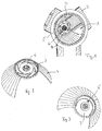
- Fig. 1 and 2 show a first embodiment, a distributor member 1 a Air conditioning system of a motor vehicle, which air with an air duct system three air ducts 2 corresponding air outlets, in this case the footwell ventilation, Windscreen defrosting and ventilation of the vehicle interior, as needed.
- the distributor element 1 is in one Type housing rotatably arranged, in which also the entrances of the air ducts 2 are integrated.
- the distributor element 1 has a frusto-conical shape with an opening 3 in its lateral surface 4.
- the opening 3 is about a One third of the entire lateral surface 4 a.
- the embodiment of the opening 3 corresponds essentially to that of the entries in the air ducts 2.
- the end face 6 of the distributor element 1 has approximately six triangular openings 7, which serve that the lateral surface 4 not necessarily completely concentric with the axis of rotation must be aligned, but can invest in the housing. to Optimization of the system to the housing is the lateral surface 4 in the area the opening 3 formed slotted at the end face 6.
- the coupling of individual distributor organs is by means of gears, for example by means of gears, friction wheels, belt drive, possible, the gears not directly with the Verteilerorganen and not directly connected have to be.
- the drive can, for example, directly by hand or by means of a suitably controlled electric servomotor.
- Fig. 3 second embodiment is substantially with the first embodiment described above, however the end face 6 'a single, crescent-shaped opening 7' for optimization the system to the housing.
Landscapes
- Physics & Mathematics (AREA)
- Thermal Sciences (AREA)
- Engineering & Computer Science (AREA)
- Mechanical Engineering (AREA)
- Air-Conditioning For Vehicles (AREA)
- Air-Flow Control Members (AREA)
Abstract
Description
- Fig. 1
- ein erstes Ausführungsbeispiel im eingebauten Zustand,
- Fig. 2
- das Verteilerorgan Fig. 1 aus einer anderen Perspektive, und
- Fig. 3
- ein zweites Ausführungsbeispiel.
Claims (11)
- Vorrichtung zur Verteilung von Luft, insbesondere in einer Klimaanlage eines Kraftfahrzeugs, auf ein Luftkanalsystem mit mehreren Luftkanälen (2), welche Luft zu verschiedenen Luftauslässen leiten, mit einem drehbar in einem Gehäuse angeordneten Verteilerorgan (1), das durch Drehung einzelne Luftkanäle (2) des Luftkanalsystems mittels einer im Verteilerorgan (1) angeordneten Öffnung (3) freigibt, dadurch gekennzeichnet, dass das Verteilerorgan (1) zumindest einen elastischen Bereich aufweist.
- Vorrichtung nach Anspruch 1, dadurch gekennzeichnet, dass das Verteilerorgan (1) mit einem Teil im Bereich der Öffnung (2) zumindest bei durchströmender Luft in Anlage an das Gehäuse ist.
- Vorrichtung nach Anspruch 1 oder 2, dadurch gekennzeichnet, dass das Verteilerorgan (1) glockenförmig oder kegelstumpfförmig ausgebildet ist.
- Vorrichtung nach einem der vorhergehenden Ansprüche, dadurch gekennzeichnet, dass das Verteilerorgan (1) zentral, insbesondere im engeren Teil des Verteilerorgans (1), drehbar gelagert ist.
- Vorrichtung nach einem der vorhergehenden Ansprüche, dadurch gekennzeichnet, dass das Verteilerorgan (1) eine Folie aufweist.
- Vorrichtung nach Anspruch 5, dadurch gekennzeichnet, dass das Verteilerorgan (1) ein die Folie stützendes Gerüst aufweist.
- Vorrichtung nach Anspruch 6, dadurch gekennzeichnet, dass die Folie mit dem Gerüst verbunden ist.
- Vorrichtung nach einem der vorhergehenden Ansprüche, dadurch gekennzeichnet, dass das Verteilerorgan (1) ein dünnwandiges Kunststoff-Spritzgussteil ist.
- Vorrichtung nach einem der vorhergehenden Ansprüche, dadurch gekennzeichnet, dass das Verteilerorgan (1) eine elastische Lagerung aufweist.
- Vorrichtung nach einem der vorhergehenden Ansprüche, dadurch gekennzeichnet, dass das Verteilerorgan (1) einen elastischen Bereich in der Nähe der Lagerung aufweist.
- Vorrichtung nach Anspruch 10, dadurch gekennzeichnet, dass der elastische Bereich durch eine oder mehrere Öffnungen (7; 7') im Bereich einer Stirnfläche (6; 6') gebildet ist.
Applications Claiming Priority (2)
| Application Number | Priority Date | Filing Date | Title |
|---|---|---|---|
| DE2002143262 DE10243262A1 (de) | 2002-09-17 | 2002-09-17 | Vorrichtung zur Verteilung von Luft, insbesondere in einer Klimaanlage eines Kraftfahrzeuges |
| DE10243262 | 2002-09-17 |
Publications (3)
| Publication Number | Publication Date |
|---|---|
| EP1400382A2 true EP1400382A2 (de) | 2004-03-24 |
| EP1400382A3 EP1400382A3 (de) | 2004-05-19 |
| EP1400382B1 EP1400382B1 (de) | 2008-04-09 |
Family
ID=31896141
Family Applications (1)
| Application Number | Title | Priority Date | Filing Date |
|---|---|---|---|
| EP20030019716 Expired - Lifetime EP1400382B1 (de) | 2002-09-17 | 2003-08-29 | Vorrichtung zur Verteilung von Luft, insbesondere in einer Klimaanlage eines Kraftfahrzeugs |
Country Status (2)
| Country | Link |
|---|---|
| EP (1) | EP1400382B1 (de) |
| DE (2) | DE10243262A1 (de) |
Families Citing this family (1)
| Publication number | Priority date | Publication date | Assignee | Title |
|---|---|---|---|---|
| DE102004054838A1 (de) * | 2004-11-12 | 2006-05-24 | Behr Gmbh & Co. Kg | Steuerorgan |
Citations (1)
| Publication number | Priority date | Publication date | Assignee | Title |
|---|---|---|---|---|
| WO2001087654A1 (en) | 2000-05-17 | 2001-11-22 | Llanelli Radiators Limited | Automotive air distribution apparatus |
Family Cites Families (9)
| Publication number | Priority date | Publication date | Assignee | Title |
|---|---|---|---|---|
| DE3805168A1 (de) * | 1988-02-19 | 1989-08-31 | Ford Werke Ag | Verteileinrichtung fuer heiz- und belueftungsanlagen von kraftfahrzeugen |
| DE3820525A1 (de) * | 1988-06-16 | 1989-12-21 | Opel Adam Ag | Luftverteiler |
| DE19808676A1 (de) * | 1998-03-02 | 1999-09-09 | Valeo Klimasysteme Gmbh | Verteilerklappe |
| FR2780133B1 (fr) * | 1998-06-23 | 2000-08-11 | Valeo Climatisation | Obturateur pour conduite de section circulaire, notamment pour systeme de climatisation de vehicule automobile |
| DE19837338C1 (de) * | 1998-08-18 | 1999-09-23 | Mc Micro Compact Car Ag | Steuerorgan für eine Luftverteilungsvorrichtung für Fahrgastzellen |
| US6296562B1 (en) * | 1998-09-08 | 2001-10-02 | Denso Corporation | Air passage switching device and air conditioning apparatus having the same |
| FR2785854B1 (fr) * | 1998-11-12 | 2001-11-16 | Valeo Climatisation | Appareil de chauffage-climatisation et/ou de climatisation comportant un ou plusieurs volets commandes par un dispositif de commande |
| JP4300340B2 (ja) * | 2000-02-14 | 2009-07-22 | 株式会社デンソー | 通風路切替用ドア |
| JP2002012016A (ja) * | 2000-06-29 | 2002-01-15 | Denso Corp | 内外気切替装置 |
-
2002
- 2002-09-17 DE DE2002143262 patent/DE10243262A1/de not_active Withdrawn
-
2003
- 2003-08-29 EP EP20030019716 patent/EP1400382B1/de not_active Expired - Lifetime
- 2003-08-29 DE DE50309567T patent/DE50309567D1/de not_active Expired - Lifetime
Patent Citations (1)
| Publication number | Priority date | Publication date | Assignee | Title |
|---|---|---|---|---|
| WO2001087654A1 (en) | 2000-05-17 | 2001-11-22 | Llanelli Radiators Limited | Automotive air distribution apparatus |
Also Published As
| Publication number | Publication date |
|---|---|
| EP1400382A3 (de) | 2004-05-19 |
| EP1400382B1 (de) | 2008-04-09 |
| DE10243262A1 (de) | 2004-03-25 |
| DE50309567D1 (de) | 2008-05-21 |
Similar Documents
| Publication | Publication Date | Title |
|---|---|---|
| DE3144899C2 (de) | ||
| DE102017115012B3 (de) | Belüftungskanal für eine Lüftungsvorrichtung eines Kraftfahrzeugs | |
| EP1800918B1 (de) | Luftausströmer mit Drallströmung | |
| EP3041696B1 (de) | System mit einer steuereinheit | |
| EP1783029A1 (de) | Vorrichtung für ein Lenksystem, insbesondere eines Kraftfahrzeugs | |
| EP1634735B1 (de) | Modulare Kraftfahrzeugklimaanlage | |
| DE102008018762A1 (de) | Betätigungsvorrichtung für ein Luftstromsteuerelement in einem Luftausströmer | |
| EP1961594A2 (de) | Luftkanal, insbesondere für ein Kraftfahrzeug | |
| EP1400382B1 (de) | Vorrichtung zur Verteilung von Luft, insbesondere in einer Klimaanlage eines Kraftfahrzeugs | |
| DE19816013A1 (de) | Luftstromverteiler für einen Kraftfahrzeuginnenraum | |
| EP1761405B1 (de) | Klimaanlage, insbesondere kraftfahrzeug-klimaanlage | |
| DE2424938C2 (de) | Anordnung von Baugruppen einer Klimaanlage in einem Kraftfahrzeug | |
| EP1348582B1 (de) | Heizungs- oder Klimaanlage für ein Kraftfahrzeug | |
| EP2390123A1 (de) | Anlage zur Steuerung wenigstens zweier Luftströme | |
| DE102006000804A1 (de) | Anordnung einer Kraftfahrzeug-Klimaanlage in einem Kraftfahrzeug | |
| EP1407903B1 (de) | Heizungs- oder Klimaanlage für ein Kraftfahrzeug mit einer Vorrichtung zur Regelung der Luftzufuhr | |
| EP0927107B1 (de) | Heizungs- und/oder klimaeinrichtung | |
| EP1522435B1 (de) | Vorrichtung zum Verschliessen und Freigeben von Luftdurchtritts-Öffnungen und Klimaanlage mit einer derartigen Vorrichtung | |
| EP1738941A1 (de) | Kraftfahrzeug-Klimaanlage | |
| DE60103719T2 (de) | Luftverteilungsvorrichtung für fahrzeuge | |
| EP1641641B1 (de) | Belüftungsvorrichtung, insbesondere für eine heizung oder klimaanlage eines kraftfahrzeugs | |
| EP1479545B1 (de) | Klimaanlage, insbesondere für Fahrzeuge sowie Verfahren zur Klimatisierung | |
| DE2403316A1 (de) | Steuervorrichtung fuer klimaanlagen | |
| DE10258955A1 (de) | Bedieneinrichtung für eine Fahrzeugklimaanlage | |
| WO2019096572A1 (de) | Einstellbare lenkradbelüftung |
Legal Events
| Date | Code | Title | Description |
|---|---|---|---|
| PUAI | Public reference made under article 153(3) epc to a published international application that has entered the european phase |
Free format text: ORIGINAL CODE: 0009012 |
|
| AK | Designated contracting states |
Kind code of ref document: A2 Designated state(s): AT BE BG CH CY CZ DE DK EE ES FI FR GB GR HU IE IT LI LU MC NL PT RO SE SI SK TR |
|
| AX | Request for extension of the european patent |
Extension state: AL LT LV MK |
|
| PUAL | Search report despatched |
Free format text: ORIGINAL CODE: 0009013 |
|
| AK | Designated contracting states |
Kind code of ref document: A3 Designated state(s): AT BE BG CH CY CZ DE DK EE ES FI FR GB GR HU IE IT LI LU MC NL PT RO SE SI SK TR |
|
| AX | Request for extension of the european patent |
Extension state: AL LT LV MK |
|
| RAP1 | Party data changed (applicant data changed or rights of an application transferred) |
Owner name: BEHR GMBH & CO. KG |
|
| 17P | Request for examination filed |
Effective date: 20041119 |
|
| AKX | Designation fees paid |
Designated state(s): DE ES FR GB IT |
|
| 17Q | First examination report despatched |
Effective date: 20050223 |
|
| 17Q | First examination report despatched |
Effective date: 20050223 |
|
| 17Q | First examination report despatched |
Effective date: 20050223 |
|
| GRAP | Despatch of communication of intention to grant a patent |
Free format text: ORIGINAL CODE: EPIDOSNIGR1 |
|
| GRAS | Grant fee paid |
Free format text: ORIGINAL CODE: EPIDOSNIGR3 |
|
| GRAA | (expected) grant |
Free format text: ORIGINAL CODE: 0009210 |
|
| AK | Designated contracting states |
Kind code of ref document: B1 Designated state(s): DE ES FR GB IT |
|
| REG | Reference to a national code |
Ref country code: GB Ref legal event code: FG4D Free format text: NOT ENGLISH |
|
| REF | Corresponds to: |
Ref document number: 50309567 Country of ref document: DE Date of ref document: 20080521 Kind code of ref document: P |
|
| PG25 | Lapsed in a contracting state [announced via postgrant information from national office to epo] |
Ref country code: ES Free format text: LAPSE BECAUSE OF FAILURE TO SUBMIT A TRANSLATION OF THE DESCRIPTION OR TO PAY THE FEE WITHIN THE PRESCRIBED TIME-LIMIT Effective date: 20080720 |
|
| ET | Fr: translation filed | ||
| PLBE | No opposition filed within time limit |
Free format text: ORIGINAL CODE: 0009261 |
|
| STAA | Information on the status of an ep patent application or granted ep patent |
Free format text: STATUS: NO OPPOSITION FILED WITHIN TIME LIMIT |
|
| 26N | No opposition filed |
Effective date: 20090112 |
|
| GBPC | Gb: european patent ceased through non-payment of renewal fee |
Effective date: 20080829 |
|
| PG25 | Lapsed in a contracting state [announced via postgrant information from national office to epo] |
Ref country code: IT Free format text: LAPSE BECAUSE OF FAILURE TO SUBMIT A TRANSLATION OF THE DESCRIPTION OR TO PAY THE FEE WITHIN THE PRESCRIBED TIME-LIMIT Effective date: 20080409 |
|
| PG25 | Lapsed in a contracting state [announced via postgrant information from national office to epo] |
Ref country code: GB Free format text: LAPSE BECAUSE OF NON-PAYMENT OF DUE FEES Effective date: 20080829 |
|
| PGFP | Annual fee paid to national office [announced via postgrant information from national office to epo] |
Ref country code: FR Payment date: 20110830 Year of fee payment: 9 |
|
| REG | Reference to a national code |
Ref country code: FR Ref legal event code: ST Effective date: 20130430 |
|
| PG25 | Lapsed in a contracting state [announced via postgrant information from national office to epo] |
Ref country code: FR Free format text: LAPSE BECAUSE OF NON-PAYMENT OF DUE FEES Effective date: 20120831 |
|
| REG | Reference to a national code |
Ref country code: DE Ref legal event code: R082 Ref document number: 50309567 Country of ref document: DE Representative=s name: GRAUEL, ANDREAS, DIPL.-PHYS. DR. RER. NAT., DE |
|
| REG | Reference to a national code |
Ref country code: DE Ref legal event code: R081 Ref document number: 50309567 Country of ref document: DE Owner name: MAHLE INTERNATIONAL GMBH, DE Free format text: FORMER OWNER: BEHR GMBH & CO. KG, 70469 STUTTGART, DE Effective date: 20150304 Ref country code: DE Ref legal event code: R082 Ref document number: 50309567 Country of ref document: DE Representative=s name: GRAUEL, ANDREAS, DIPL.-PHYS. DR. RER. NAT., DE Effective date: 20150304 |
|
| PGFP | Annual fee paid to national office [announced via postgrant information from national office to epo] |
Ref country code: DE Payment date: 20180831 Year of fee payment: 16 |
|
| REG | Reference to a national code |
Ref country code: DE Ref legal event code: R119 Ref document number: 50309567 Country of ref document: DE |
|
| PG25 | Lapsed in a contracting state [announced via postgrant information from national office to epo] |
Ref country code: DE Free format text: LAPSE BECAUSE OF NON-PAYMENT OF DUE FEES Effective date: 20200303 |