EP1400290A1 - Maschinelle Biegevorrichtung sowie maschinelle Anordnung mit einer derartigen Biegevorrichtung - Google Patents
Maschinelle Biegevorrichtung sowie maschinelle Anordnung mit einer derartigen Biegevorrichtung Download PDFInfo
- Publication number
- EP1400290A1 EP1400290A1 EP02021107A EP02021107A EP1400290A1 EP 1400290 A1 EP1400290 A1 EP 1400290A1 EP 02021107 A EP02021107 A EP 02021107A EP 02021107 A EP02021107 A EP 02021107A EP 1400290 A1 EP1400290 A1 EP 1400290A1
- Authority
- EP
- European Patent Office
- Prior art keywords
- bending
- drive
- workpiece
- hold
- tool
- Prior art date
- Legal status (The legal status is an assumption and is not a legal conclusion. Google has not performed a legal analysis and makes no representation as to the accuracy of the status listed.)
- Granted
Links
- 238000005452 bending Methods 0.000 title claims abstract description 162
- 230000008878 coupling Effects 0.000 claims description 14
- 238000010168 coupling process Methods 0.000 claims description 14
- 238000005859 coupling reaction Methods 0.000 claims description 14
- 238000003754 machining Methods 0.000 claims description 10
- 230000009471 action Effects 0.000 claims description 5
- 238000000926 separation method Methods 0.000 claims description 3
- 230000004913 activation Effects 0.000 description 4
- 230000008901 benefit Effects 0.000 description 2
- 238000010276 construction Methods 0.000 description 2
- 238000004519 manufacturing process Methods 0.000 description 2
- 238000000034 method Methods 0.000 description 2
- 230000008569 process Effects 0.000 description 2
- 230000008859 change Effects 0.000 description 1
- 230000009849 deactivation Effects 0.000 description 1
- 230000001419 dependent effect Effects 0.000 description 1
- 230000000694 effects Effects 0.000 description 1
- 230000000977 initiatory effect Effects 0.000 description 1
- 238000003780 insertion Methods 0.000 description 1
- 230000037431 insertion Effects 0.000 description 1
- 238000003698 laser cutting Methods 0.000 description 1
- 239000002184 metal Substances 0.000 description 1
- 238000004080 punching Methods 0.000 description 1
- XLYOFNOQVPJJNP-UHFFFAOYSA-N water Substances O XLYOFNOQVPJJNP-UHFFFAOYSA-N 0.000 description 1
Images




Classifications
-
- B—PERFORMING OPERATIONS; TRANSPORTING
- B21—MECHANICAL METAL-WORKING WITHOUT ESSENTIALLY REMOVING MATERIAL; PUNCHING METAL
- B21D—WORKING OR PROCESSING OF SHEET METAL OR METAL TUBES, RODS OR PROFILES WITHOUT ESSENTIALLY REMOVING MATERIAL; PUNCHING METAL
- B21D5/00—Bending sheet metal along straight lines, e.g. to form simple curves
- B21D5/04—Bending sheet metal along straight lines, e.g. to form simple curves on brakes making use of clamping means on one side of the work
- B21D5/042—With a rotational movement of the bending blade
Definitions
- the invention relates to a mechanical bending device for Bending plate-like workpieces, in particular sheets, with at least one bending tool, the at least one having a movable tool part by means of a bending drive, wherein the workpiece under the action of the moving Tool part is bendable along a bending line and the movable Tool part in the direction of the bending line consecutive Tool parts segments includes.
- the invention relates to Furthermore, a machine arrangement with one described above Bender.
- At least one tool part segment used which can be either drive-connected with the bending drive is. Always only those tool part segments are under the action of the workpiece to be deformed to actually move that for creating the desired bend needed. The remaining tool part segments can remain in rest position. For each bending process is thus the right bending tool available, without that to this Purpose to perform a tool change would be.
- Bending tool a swivel bending tool with demand-driven Biegewangensegmenten provided.
- inventive Using a swivel bending tool offers the advantage that during workpiece machining only the bent Workpiece leg leaves its starting position. The rest Workpiece can during the machining process - unlike For example, during die bending - maintained its initial position.
- Claim 7 not only under bending admission of the workpiece to be deformed movable tool part but also an associated with this tool part Downholder divided into segments.
- the hold-down segments can optionally be drive-connected with a hold-down drive become.
- a connection with the associated drive is produced for those hold-down and Biegewangensegmente, which in the workpiece machining with each other interact.
- the workpiece is only in that area of the hold-down or hold-down segments in which the desired bend to create is.
- hold-down segments can from the workpiece be spaced. This possibility is especially of Advantage, if at the workpiece a bend near one already existing bend is to create. The admission is limited of the workpiece with hold - down segments on the Workpiece area of the additional bend, so will an undesirable Deformation of the existing bend by Hold-down segments avoided.
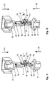
- a bending machine 1 has a C-shaped machine frame 2 with an upper frame leg 3 and a lower frame legs 4.
- a conventional coordinate guide 5 is housed in the throat of the bending machine 1 between the upper frame leg 3 and the lower frame leg 4.
- a workpiece to be machined in the form of a sheet 6 is at the coordinate guide 5 by means not shown Spannpratzen held and by appropriate movement of the Coordinate guide 5 movable in the horizontal plane of the sheet.
- the coordinate guide 5 In its movement by means of the coordinate guide 5 that rests Sheet 6 on a workpiece table 7 of conventional design, which at the Top of the lower frame leg 4 is attached.
- the bending tool is shown 9 about a pivoting bending tool with a bending cheek 14, a Downholder 15 and a workpiece support 16.
- the bending cheek 14 is composed of five bending beam segments 17, the hold-down 15 composed of five hold-down segments 18. Both the Biegewangensegmente 17 and the hold-down segments 18th are in the direction of the bending cheek 14 in cooperation lined up with the hold-15 bending line 11 strung together.
- the bending beam segments 17 are designed as a pivot lever and each have a bending arm 19 and a drive arm 20. They are pivotable about a pivot axis 21 on a bending cheek holder 22 of the bending station 8 stored.
- the drive arms 20 are each supported by their free ends on a control track 23, which in turn provided on a control 24 is.
- the controls 24 are on the bending cheek holder 22 guided linearly displaceable.
- About coupling parts 25 can the controls 24 with a piston 26 of a bending drive 27 are drive connected.
- Each control 24 is a individual coupling part 25 assigned.
- the coupling parts 25 can by means not shown actuators individually between the controls 24 and the piston 26 of the bending drive 27 are inserted or disengaged.
- the controls 24 and the piston 26 of the bending drive 27 also over a coupling part be coupled, which in the direction of Pivot axis 21 between the controls 24 and the piston 26 is inserted and whose length is dimensioned such that depending on the insertion position between one or more, maximum all controls 24 on the one hand and the piston 26 on the other can be arranged.
- the clutch the controls 24 and the piston 26 a wave-like Provide component whose axial direction parallel to the Swivel axis 21 runs and in this direction to each other having the following shaft sections, the different controls 24 are assigned and in the circumferential direction of the shaft form mutually offset radial projections, wherein in Dependence on the rotational position of the shaft with respect to her Axis a different number of shaft sections effective is and therefore a different number of Controls 24 via radial shaft projections with the piston 26 is drive connected.
- Each of the hold-down segments 18 is assigned a coupling part 28.
- adjusting device can be the coupling parts 28 individually between the hold-down segments 18 and a piston 29 a hold-down drive 30 on or disengage.
- the Hold-down segments 18 are in the direction of movement of the piston 29 guided linearly movable on a hold-down support 31.
- the coupling parts 25 by structurally different components for the production a drive connection between the piston 29 of the Hold-down drive 30 and the hold-down segments 18 replaced be.
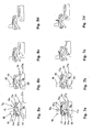
- FIG. 1 The initial situation before the beginning of the bending processing of the Sheet 6 is shown in FIG.
- the dashed line indicated Plate 6 rests on the workpiece support 16.
- the bending cheek 14 or the bending beam segments 17 take their starting position one.
- the hold-down 15 and the hold-down segments 18 are withdrawn relative to the sheet 6.
- the coupling parts 25, 28 are disengaged. There is therefore no drive connection between the bending beam segments 17 and the bending drive 27 still a drive connection between the hold-down segments 18 and the hold-down drive 30.
- the hold-down drive 30 is pressed, the previously activated, i. with the Hold-down drive 30 drive-connected hold-down segments 18 on the plate 6 from.
- the activated hold-down segments 18 with their projecting Ends in that area of the sheet 6 to the support, in which the Homelandkantende flat tab 13 to the rest of the sheet 6 connects ( Figure 5). Due to the means of Niederhalterantriebes 30 applied contact pressure is the plate 6 between the effective hold-down segments 18 and the workpiece support 16 fixed secured against any movement.
- a bending tool shown in FIGS. 7a to 7d and 8a to 8d 9a differs from the bending tool 9 according to FIG Figures 2 to 6 substantially with respect to the activation and actuation of a bending cheek 14a. So serves for activation and deactivation of pivoting lever-type bending beam segments 17a a switching device 34 in the form of an actuating cylinder. there each bending beam segment 17a is a separate adjusting device 34 assigned.
- Biegewangensegmente 17a which in the subsequent workpiece machining are to be used, by means of the switching device 34 on a drive arm 20a in a receptacle 35 at a Driver 36 of a bending drive 27a engaged. Will the Driver 36 then from its initial position according to FIG 7a shifted to its end position according to Figure 7d, so takes he the drive arm 20a of the or the engaged bending beam segments 17a with. As a result, the respective bending cheek segments pivot 17a about its pivot axis 21 and deform the Sheet 6 by means of a bending arm 19a in the desired manner. Biegewangensegmente 17a, in the processing of the sheet.
- a double tool 37 shown in FIG. 9 comprises two each other in construction and operation corresponding bending tools 9, which are arranged rotated by 180 ° from each other. On one and the same side of the sheet to be machined 6 lie Therefore, each one hold-down 15 of the one and a bending cheek 14 of the other bending tool 9. Due to the given philosophicales can at the bending tools 9 bends with each other opposite directions are created. In FIG. 9 indicated is a downwardly bent tab of the sheet. 6
- Clutch parts 25, 28 are optional on both sides of the sheet 6 for activation of a bending cheek 14 or for activation a hold-down 15 usable.
- a hydraulic drive functions, depending on which of the bending tool parts activated is as a bending drive 27 with piston 26 or as hold-down drive 30 with piston 29.
- the bending station 8 is integrated in one mechanical arrangement 38 for processing the sheet 6, in addition a machine separator 39 for separating Processing the sheet 6 includes.
- the separator 39 In the example shown, this is a punching device. Without further thought, for example, are also a Water, a plasma and / or a laser cutting device.
- the separator 39 are first at the level Sheet metal 6 tabs cut free on three sides. Subsequently is the sheet 6 by means of the coordinate guide 5 with respect to Bending station 8 positioned such that by means of the bending station 8 folded the flat tabs in the manner shown can be.
- the machine functions are in all of the above Machining CNC controlled.
Landscapes
- Engineering & Computer Science (AREA)
- Mechanical Engineering (AREA)
- Bending Of Plates, Rods, And Pipes (AREA)
- Wire Processing (AREA)
Abstract
Description
- Figur 1
- eine Biegemaschine bei der biegenden Bearbeitung eines Bleches,
- Figuren 2 bis 6
- den Ablauf eines Biegevorganges anhand der sich dabei ergebenden Betriebszustände eines an der Biegemaschine gemäß Figur 1 einsetzbaren Biegewerkzeuges erster Bauart,
- Figuren 7a bis 7d und 8a bis 8d
- Darstellungen zu der Funktionsweise eines an der Biegemaschine gemäß Figur 1 einsetzbaren Biegewerkzeuges zweiter Bauart,
- Figur 9
- ein an der Biegemaschine gemäß Figur 1 einsetzbares Doppelwerkzeug und
- Figur 10
- eine maschinelle Anordnung zum Bearbeiten von Blechen mit einer Biege- sowie mit einer Trennstation.
Claims (10)
- Maschinelle Biegevorrichtung zum Biegen von plattenartigen Werkstücken, insbesondere von Blechen (6), mit zumindest einem Biegewerkzeug (9, 9a), das wenigstens einen mittels eines Biegeantriebs (27, 27a) bewegbaren Werkzeugteil aufweist, wobei das Werkstück unter Beaufschlagung mittels des bewegten Werkzeugteils entlang einer Biegelinie (11) biegbar ist und der bewegbare Werkzeugteil in Richtung der Biegelinie (11) aufeinanderfolgende Werkzeugteilsegmente umfasst, dadurch gekennzeichnet, dass wenigstens ein Werkzeugteilsegment wahlweise mit dem Biegeantrieb (27, 27a) antriebsverbindbar ist.
- Maschinelle Biegevorrichtung nach Anspruch 1, dadurch gekennzeichnet, dass als Biegewerkzeug (9, 9a) ein Schwenkbiegewerkzeug vorgesehen ist mit einem bewegbaren Werkzeugteil in Form einer um eine in Richtung der Biegelinie (11) verlaufende Schwenkachse (21) schwenkbaren Biegewange (14, 14a) und dass die Biegewange (14, 14a) Werkzeugteilsegmente in Form von Biegewangensegmenten (17, 17a) umfasst, von denen wenigstens eines wahlweise mit dem Biegeantrieb (27, 27a) antriebsverbindbar und bei hergestellter Antriebsverbindung unter biegender Beaufschlagung des Werkstücks um die Schwenkachse (21) schwenkbar ist.
- Maschinelle Biegevorrichtung nach einem der vorhergehenden Ansprüche, dadurch gekennzeichnet, dass wenigstens ein Biegewangensegment (17, 17a) als zweiarmiger Schwenkhebel ausgebildet ist mit einem an der einen Seite der Schwenkachse (21) vorgesehenen Biegearm (19, 19a) zur biegenden Beaufschlagung des Werkstücks sowie mit einem an der anderen Seite der Schwenkachse (21) vorgesehenen Antriebsarm (20, 20a), zur wahlweisen Herstellung der Antriebsverbindung mit dem Biegeantrieb (27, 27a).
- Maschinelle Biegevorrichtung nach einem der vorhergehenden Ansprüche, dadurch gekennzeichnet, dass wenigstens ein Schwenkhebel mittels einer Schalteinrichtung (34) antriebsarmseitig wahlweise in eine Aufnahme (35) an einem Mitnehmer (36) des Biegeantriebes (27a) einrückbar oder aus dieser Aufnahme (35) ausrückbar ist, wobei die Antriebsverbindung zwischen dem Schwenkhebel und dem Biegeantrieb (27a) bei eingerücktem Zustand hergestellt und bei ausgerücktem Zustand getrennt ist.
- Maschinelle Biegevorrichtung nach einem der vorhergehenden Ansprüche, dadurch gekennzeichnet, dass zwischen wenigstens einem Schwenkhebel und dem Biegeantrieb (27) ein Steuerelement (24) mit einer Steuerbahn (23) vorgesehen ist, wobei der Schwenkhebel antriebsarmseitig an der Steuerbahn (23) des Steuerelementes (24) abgestützt ist und dieses biegeantriebsseitig mittels einer Schalteinrichtung wahlweise mit dem Biegeantrieb (27) antriebsverbindbar ist, wobei der Schwenkhebel bei hergestellter Antriebsverbindung zwischen dem Steuerelement (24) und dem Biegeantrieb (27) von dem Steuerelement (24) über dessen Steuerbahn (23) antriebsarmseitig beaufschlagt und dadurch unter biegender Beaufschlagung des Werkstücks um die Schwenkachse (21) schwenkbar ist.
- Maschinelle Biegevorrichtung nach einem der vorhergehenden Ansprüche, dadurch gekennzeichnet, dass die Schalteinrichtung zur wahlweisen Antriebsverbindung von Steuerelement (24) und Biegeantrieb (27) wenigstens ein wahlweise zwischen dem Steuerelement (24) und dem Biegeantrieb (27) ein- oder ausrückbares Kupplungsteil (25) aufweist, wobei die Antriebsverbindung zwischen dem Steuerelement (24) und dem Biegeantrieb (27) bei eingerücktem Kupplungsteil (25) hergestellt und bei ausgerücktem Kupplungsteil (25) getrennt ist.
- Maschinelle Biegevorrichtung nach einem der vorhergehenden Ansprüche, dadurch gekennzeichnet, dass das als Schwenkbiegewerkzeug ausgebildete Biegewerkzeug (9, 9a) einen sich entlang der Biegelinie (11) erstreckenden Niederhalter (15) aufweist, mittels dessen das Werkstück in Querrichtung seiner flächigen Erstreckung beaufschlagbar und dadurch zwischen dem Niederhalter (15) und einer Werkstückauflage (16) an der dem Niederhalter (15) gegenüberliegenden Werkstückseite fixierbar ist und dass der Niederhalter (15) in Richtung der Biegelinie (11) aufeinanderfolgende Niederhaltersegmente (18) umfasst, von denen wenigstens eines wahlweise mit einem Niederhalterantrieb (30) antriebsverbindbar und durch Herstellung der Antriebsverbindung in eine das Werkstück beaufschlagende Position überführbar ist, wobei beim Biegen des Werkstückes miteinander zusammenwirkende Niederhaltersegmente (18) und Biegewangensegmente (17, 17a) zeitgleich mit dem Niederhalterantrieb (30) oder mit dem Biegeantrieb (27, 27a) antriebsverbunden sind.
- Maschinelle Biegevorrichtung nach einem der vorhergehenden Ansprüche, dadurch gekennzeichnet, dass zumindest zwei Biegewerkzeuge (9) in Form von Schwenkbiegewerkzeugen vorgesehen sind, von denen jedes eine schwenkbare Biegewange (14) mit wenigstens einem wahlweise mit dem Biegeantrieb (27) antriebsverbindbaren Biegewangensegment (17) sowie einen Niederhalter (15) aufweist, wobei jeweils die Biegewange (14) des einen und der Niederhalter (15) des anderen Biegewerkzeuges (9) an ein und derselben Seite des Werkstückes angeordnet sind.
- Maschinelle Biegevorrichtung nach einem der vorhergehenden Ansprüche, dadurch gekennzeichnet, dass wenigstens an einer Seite des Werkstücks der Niederhalter (15) einen Niederhalterantrieb (30) aufweist und der Biegeantrieb (27) des einen und der Niederhalterantrieb (30) des anderen Biegewerkzeuges (9) zumindest ein gemeinsames Antriebselement aufweisen.
- Maschinelle Anordnung zum Bearbeiten von plattenartigen Werkstücken, insbesondere von Blechen (6), dadurch gekennzeichnet, dass wenigstens eine maschinelle Biegevorrichtung (8) nach einem der Ansprüche 1 bis 9 und außerdem wenigstens eine maschinelle Trennvorrichtung (39) zur trennenden Werkstückbearbeitung vorgesehen sind, wobei an der maschinellen Biegevorrichtung (8) mittels der maschinellen Trennvorrichtung (39) trennend bearbeitete Werkstückteile biegend bearbeitbar sind.
Priority Applications (5)
| Application Number | Priority Date | Filing Date | Title |
|---|---|---|---|
| DE50208077T DE50208077D1 (de) | 2002-09-23 | 2002-09-23 | Maschinelle Biegevorrichtung sowie maschinelle Anordnung mit einer derartigen Biegevorrichtung |
| EP02021107A EP1400290B1 (de) | 2002-09-23 | 2002-09-23 | Maschinelle Biegevorrichtung sowie maschinelle Anordnung mit einer derartigen Biegevorrichtung |
| AT02021107T ATE338591T1 (de) | 2002-09-23 | 2002-09-23 | Maschinelle biegevorrichtung sowie maschinelle anordnung mit einer derartigen biegevorrichtung |
| US10/669,039 US6955071B2 (en) | 2002-09-23 | 2003-09-23 | Mechanical bending apparatus |
| JP2003331416A JP4541671B2 (ja) | 2002-09-23 | 2003-09-24 | 機械的な曲げ装置及び該曲げ装置を備えた機械装置 |
Applications Claiming Priority (1)
| Application Number | Priority Date | Filing Date | Title |
|---|---|---|---|
| EP02021107A EP1400290B1 (de) | 2002-09-23 | 2002-09-23 | Maschinelle Biegevorrichtung sowie maschinelle Anordnung mit einer derartigen Biegevorrichtung |
Publications (2)
| Publication Number | Publication Date |
|---|---|
| EP1400290A1 true EP1400290A1 (de) | 2004-03-24 |
| EP1400290B1 EP1400290B1 (de) | 2006-09-06 |
Family
ID=31896898
Family Applications (1)
| Application Number | Title | Priority Date | Filing Date |
|---|---|---|---|
| EP02021107A Expired - Lifetime EP1400290B1 (de) | 2002-09-23 | 2002-09-23 | Maschinelle Biegevorrichtung sowie maschinelle Anordnung mit einer derartigen Biegevorrichtung |
Country Status (5)
| Country | Link |
|---|---|
| US (1) | US6955071B2 (de) |
| EP (1) | EP1400290B1 (de) |
| JP (1) | JP4541671B2 (de) |
| AT (1) | ATE338591T1 (de) |
| DE (1) | DE50208077D1 (de) |
Cited By (1)
| Publication number | Priority date | Publication date | Assignee | Title |
|---|---|---|---|---|
| CN113927085A (zh) * | 2021-10-28 | 2022-01-14 | 怀化市产商品质量监督检验所 | 一种金属材料加工裁断装置 |
Families Citing this family (2)
| Publication number | Priority date | Publication date | Assignee | Title |
|---|---|---|---|---|
| CN105013888B (zh) * | 2015-07-29 | 2017-10-27 | 成都市松川金属材料有限公司 | 一种具有横向辅助施压的折弯机 |
| DE102019123308A1 (de) * | 2019-08-30 | 2021-03-04 | Universität Siegen | Vorrichtung und Verfahren zum Schwenkbiegen eines Werkstückes |
Citations (3)
| Publication number | Priority date | Publication date | Assignee | Title |
|---|---|---|---|---|
| GB2032308A (en) * | 1978-10-18 | 1980-05-08 | Folwell J | Sheet metal folding machine |
| DE4222357A1 (de) * | 1992-07-08 | 1994-03-24 | Hermann Schwan | Vorrichtung zum Schwenkbiegen von Blechen |
| WO1996024445A1 (en) * | 1995-02-06 | 1996-08-15 | Amada Company, Ltd. | Bending apparatus for metal sheets |
Family Cites Families (8)
| Publication number | Priority date | Publication date | Assignee | Title |
|---|---|---|---|---|
| US929818A (en) * | 1909-03-29 | 1909-08-03 | Victor Benedek | Sheet-metal brake. |
| US4112731A (en) * | 1977-01-24 | 1978-09-12 | Manufacturers Systems, Inc. | Light gauge sheet metal forming machine |
| US5067340A (en) * | 1988-05-05 | 1991-11-26 | Macgregor Donald C | Precision press brake |
| US5630336A (en) * | 1992-07-17 | 1997-05-20 | Jorgenson; Jerry N. | Bending brake |
| JPH08224618A (ja) * | 1995-02-22 | 1996-09-03 | Amada Co Ltd | 折曲げ加工機におけるカウンタ式ソロツールの交換方法およびその装置と下部金型のスラスト受け装置 |
| JPH08318320A (ja) * | 1995-05-25 | 1996-12-03 | Amada Co Ltd | 折曲げ加工機 |
| DE19640124A1 (de) * | 1996-09-28 | 1998-04-09 | Reinhardt Gmbh Maschbau | Biegemaschine |
| US5927135A (en) * | 1996-09-28 | 1999-07-27 | Reinhardt Maschinenbau Gmbh | Bending machine |
-
2002
- 2002-09-23 EP EP02021107A patent/EP1400290B1/de not_active Expired - Lifetime
- 2002-09-23 AT AT02021107T patent/ATE338591T1/de not_active IP Right Cessation
- 2002-09-23 DE DE50208077T patent/DE50208077D1/de not_active Expired - Lifetime
-
2003
- 2003-09-23 US US10/669,039 patent/US6955071B2/en not_active Expired - Lifetime
- 2003-09-24 JP JP2003331416A patent/JP4541671B2/ja not_active Expired - Fee Related
Patent Citations (3)
| Publication number | Priority date | Publication date | Assignee | Title |
|---|---|---|---|---|
| GB2032308A (en) * | 1978-10-18 | 1980-05-08 | Folwell J | Sheet metal folding machine |
| DE4222357A1 (de) * | 1992-07-08 | 1994-03-24 | Hermann Schwan | Vorrichtung zum Schwenkbiegen von Blechen |
| WO1996024445A1 (en) * | 1995-02-06 | 1996-08-15 | Amada Company, Ltd. | Bending apparatus for metal sheets |
Cited By (1)
| Publication number | Priority date | Publication date | Assignee | Title |
|---|---|---|---|---|
| CN113927085A (zh) * | 2021-10-28 | 2022-01-14 | 怀化市产商品质量监督检验所 | 一种金属材料加工裁断装置 |
Also Published As
| Publication number | Publication date |
|---|---|
| EP1400290B1 (de) | 2006-09-06 |
| JP4541671B2 (ja) | 2010-09-08 |
| US20040194531A1 (en) | 2004-10-07 |
| DE50208077D1 (de) | 2006-10-19 |
| JP2004130389A (ja) | 2004-04-30 |
| ATE338591T1 (de) | 2006-09-15 |
| US6955071B2 (en) | 2005-10-18 |
Similar Documents
| Publication | Publication Date | Title |
|---|---|---|
| EP2008736B1 (de) | Werkzeugmaschine und Verfahren zum Ausschleusen eines Werkstückteils | |
| DE102007051894A1 (de) | Freigabemechanismus und mit diesem versehenen Richtvorrichtung | |
| DE2822476A1 (de) | Einrichtung zum schneiden laenglichen profilmaterials, insbesondere von rohrmaterial | |
| DE69206153T2 (de) | Presse. | |
| WO2018055190A1 (de) | Verfahren; werkzeugmaschine und schlitzwerkzeug zum mehrhubig fortschreitenden schlitzen von plattenförmigen werkstücken | |
| EP1317974B1 (de) | Verfahren und Maschine zum mehrhubig fortschreitenden Schlitzen von plattenartigen Werkstücken, insbesondere von Blechen | |
| EP3231585A1 (de) | Vorichtung zum ultraschallschweissen | |
| EP1759820B1 (de) | Vorrichtung zum dreiseitigen Beschnitt von Produkten | |
| WO2018055180A1 (de) | Werkzeug und werkzeugmaschine sowie verfahren zur bearbeitung von plattenförmigen werkstücken | |
| DE69804227T2 (de) | Abkantpresse zur herstellung u-förmiger abkantungen an den kanten eines tafelblehes | |
| EP1400290B1 (de) | Maschinelle Biegevorrichtung sowie maschinelle Anordnung mit einer derartigen Biegevorrichtung | |
| DE69507627T2 (de) | Abkantpresse zur herstellung u-foermiger abkantungen an den vier kanten eines tafelbleches | |
| DE102015217887A1 (de) | Werkzeug für eine Stanzmaschine zum Umformen von Abschnitten eines plattenförmigen Werkstücks und Verfahren dazu | |
| EP1495816A1 (de) | Biegewerkzeug mit einstellbaren Werkstückwiderlagersegmenten sowie Biegemaschine mit einem derartigen Biegewerkzeug | |
| DE102016120139B4 (de) | Verfahren, Werkzeugmaschine und Schlitzwerkzeug zum mehrhubig fortschreitenden Schlitzen von plattenförmigen Werkstücken | |
| EP1238723A2 (de) | Verfahren zum Abkanten von Blechen und Vorrichtung zur Durchführung des Verfahrens | |
| DE510655C (de) | Maschine zur Herstellung von Pappschachteln | |
| DE69024585T2 (de) | Winkelschermaschine speziell zum Schneiden von Metallplatten in Stücke von verschiedener Grösse | |
| DE102016119457A1 (de) | Werkzeug und Werkzeugmaschine sowie Verfahren zur Bearbeitung von plattenförmigen Werkstücken | |
| DE69504895T2 (de) | Zusatzbearbeitungseinrichtung, insbesondere zum teilweise Biegen und Schneiden in einer Abkantpresse | |
| EP0714720B1 (de) | Bearbeitungsmaschine mit Stanzeinrichtung und Einrichtung zur rollenden Werkstückbearbeitung | |
| EP1584385B1 (de) | Biegewerkzeug zum Biegen von Werkstücken, insbesondere von Blechen sowie Biegemaschine mit einem derartigen Biegewerkzeug | |
| DE3206681A1 (de) | Hydraulisch angetriebene schneidemaschine fuer papierbogen od. dgl. | |
| EP2726227B1 (de) | Biegepresse mit einer falzvorrichtung und verfahren zur durchführung einer falzung | |
| DE19845599A1 (de) | Vorrichtung und Verfahren zum Herstellen von Platinen |
Legal Events
| Date | Code | Title | Description |
|---|---|---|---|
| PUAI | Public reference made under article 153(3) epc to a published international application that has entered the european phase |
Free format text: ORIGINAL CODE: 0009012 |
|
| AK | Designated contracting states |
Kind code of ref document: A1 Designated state(s): AT BE BG CH CY CZ DE DK EE ES FI FR GB GR IE IT LI LU MC NL PT SE SK TR |
|
| AX | Request for extension of the european patent |
Extension state: AL LT LV MK RO SI |
|
| 17P | Request for examination filed |
Effective date: 20040917 |
|
| AKX | Designation fees paid |
Designated state(s): AT BE BG CH CY CZ DE DK EE ES FI FR GB GR IE IT LI LU MC NL PT SE SK TR |
|
| 17Q | First examination report despatched |
Effective date: 20041215 |
|
| GRAP | Despatch of communication of intention to grant a patent |
Free format text: ORIGINAL CODE: EPIDOSNIGR1 |
|
| GRAS | Grant fee paid |
Free format text: ORIGINAL CODE: EPIDOSNIGR3 |
|
| GRAA | (expected) grant |
Free format text: ORIGINAL CODE: 0009210 |
|
| AK | Designated contracting states |
Kind code of ref document: B1 Designated state(s): AT BE BG CH CY CZ DE DK EE ES FI FR GB GR IE IT LI LU MC NL PT SE SK TR |
|
| PG25 | Lapsed in a contracting state [announced via postgrant information from national office to epo] |
Ref country code: CZ Free format text: LAPSE BECAUSE OF FAILURE TO SUBMIT A TRANSLATION OF THE DESCRIPTION OR TO PAY THE FEE WITHIN THE PRESCRIBED TIME-LIMIT Effective date: 20060906 Ref country code: SK Free format text: LAPSE BECAUSE OF FAILURE TO SUBMIT A TRANSLATION OF THE DESCRIPTION OR TO PAY THE FEE WITHIN THE PRESCRIBED TIME-LIMIT Effective date: 20060906 Ref country code: FI Free format text: LAPSE BECAUSE OF FAILURE TO SUBMIT A TRANSLATION OF THE DESCRIPTION OR TO PAY THE FEE WITHIN THE PRESCRIBED TIME-LIMIT Effective date: 20060906 Ref country code: IE Free format text: LAPSE BECAUSE OF FAILURE TO SUBMIT A TRANSLATION OF THE DESCRIPTION OR TO PAY THE FEE WITHIN THE PRESCRIBED TIME-LIMIT Effective date: 20060906 Ref country code: NL Free format text: LAPSE BECAUSE OF FAILURE TO SUBMIT A TRANSLATION OF THE DESCRIPTION OR TO PAY THE FEE WITHIN THE PRESCRIBED TIME-LIMIT Effective date: 20060906 |
|
| REG | Reference to a national code |
Ref country code: GB Ref legal event code: FG4D Free format text: NOT ENGLISH |
|
| REG | Reference to a national code |
Ref country code: CH Ref legal event code: EP |
|
| PG25 | Lapsed in a contracting state [announced via postgrant information from national office to epo] |
Ref country code: BE Free format text: LAPSE BECAUSE OF NON-PAYMENT OF DUE FEES Effective date: 20060930 Ref country code: MC Free format text: LAPSE BECAUSE OF NON-PAYMENT OF DUE FEES Effective date: 20060930 |
|
| REG | Reference to a national code |
Ref country code: IE Ref legal event code: FG4D Free format text: LANGUAGE OF EP DOCUMENT: GERMAN |
|
| REF | Corresponds to: |
Ref document number: 50208077 Country of ref document: DE Date of ref document: 20061019 Kind code of ref document: P |
|
| PG25 | Lapsed in a contracting state [announced via postgrant information from national office to epo] |
Ref country code: BG Free format text: LAPSE BECAUSE OF FAILURE TO SUBMIT A TRANSLATION OF THE DESCRIPTION OR TO PAY THE FEE WITHIN THE PRESCRIBED TIME-LIMIT Effective date: 20061206 Ref country code: DK Free format text: LAPSE BECAUSE OF FAILURE TO SUBMIT A TRANSLATION OF THE DESCRIPTION OR TO PAY THE FEE WITHIN THE PRESCRIBED TIME-LIMIT Effective date: 20061206 Ref country code: SE Free format text: LAPSE BECAUSE OF FAILURE TO SUBMIT A TRANSLATION OF THE DESCRIPTION OR TO PAY THE FEE WITHIN THE PRESCRIBED TIME-LIMIT Effective date: 20061206 |
|
| PG25 | Lapsed in a contracting state [announced via postgrant information from national office to epo] |
Ref country code: ES Free format text: LAPSE BECAUSE OF FAILURE TO SUBMIT A TRANSLATION OF THE DESCRIPTION OR TO PAY THE FEE WITHIN THE PRESCRIBED TIME-LIMIT Effective date: 20061217 |
|
| GBT | Gb: translation of ep patent filed (gb section 77(6)(a)/1977) |
Effective date: 20061211 |
|
| PG25 | Lapsed in a contracting state [announced via postgrant information from national office to epo] |
Ref country code: PT Free format text: LAPSE BECAUSE OF FAILURE TO SUBMIT A TRANSLATION OF THE DESCRIPTION OR TO PAY THE FEE WITHIN THE PRESCRIBED TIME-LIMIT Effective date: 20070219 |
|
| NLV1 | Nl: lapsed or annulled due to failure to fulfill the requirements of art. 29p and 29m of the patents act | ||
| ET | Fr: translation filed | ||
| REG | Reference to a national code |
Ref country code: IE Ref legal event code: FD4D |
|
| PLBE | No opposition filed within time limit |
Free format text: ORIGINAL CODE: 0009261 |
|
| STAA | Information on the status of an ep patent application or granted ep patent |
Free format text: STATUS: NO OPPOSITION FILED WITHIN TIME LIMIT |
|
| 26N | No opposition filed |
Effective date: 20070607 |
|
| BERE | Be: lapsed |
Owner name: TRUMPF WERKZEUGMASCHINEN G.M.B.H. + CO. KG Effective date: 20060930 |
|
| PG25 | Lapsed in a contracting state [announced via postgrant information from national office to epo] |
Ref country code: GR Free format text: LAPSE BECAUSE OF FAILURE TO SUBMIT A TRANSLATION OF THE DESCRIPTION OR TO PAY THE FEE WITHIN THE PRESCRIBED TIME-LIMIT Effective date: 20061207 |
|
| PG25 | Lapsed in a contracting state [announced via postgrant information from national office to epo] |
Ref country code: EE Free format text: LAPSE BECAUSE OF FAILURE TO SUBMIT A TRANSLATION OF THE DESCRIPTION OR TO PAY THE FEE WITHIN THE PRESCRIBED TIME-LIMIT Effective date: 20060906 |
|
| PG25 | Lapsed in a contracting state [announced via postgrant information from national office to epo] |
Ref country code: LU Free format text: LAPSE BECAUSE OF NON-PAYMENT OF DUE FEES Effective date: 20060923 Ref country code: TR Free format text: LAPSE BECAUSE OF FAILURE TO SUBMIT A TRANSLATION OF THE DESCRIPTION OR TO PAY THE FEE WITHIN THE PRESCRIBED TIME-LIMIT Effective date: 20060906 |
|
| PG25 | Lapsed in a contracting state [announced via postgrant information from national office to epo] |
Ref country code: CY Free format text: LAPSE BECAUSE OF FAILURE TO SUBMIT A TRANSLATION OF THE DESCRIPTION OR TO PAY THE FEE WITHIN THE PRESCRIBED TIME-LIMIT Effective date: 20060906 |
|
| PGFP | Annual fee paid to national office [announced via postgrant information from national office to epo] |
Ref country code: AT Payment date: 20080820 Year of fee payment: 7 |
|
| PGFP | Annual fee paid to national office [announced via postgrant information from national office to epo] |
Ref country code: GB Payment date: 20080915 Year of fee payment: 7 |
|
| PGFP | Annual fee paid to national office [announced via postgrant information from national office to epo] |
Ref country code: CH Payment date: 20081002 Year of fee payment: 7 |
|
| REG | Reference to a national code |
Ref country code: CH Ref legal event code: PL |
|
| GBPC | Gb: european patent ceased through non-payment of renewal fee |
Effective date: 20090923 |
|
| PG25 | Lapsed in a contracting state [announced via postgrant information from national office to epo] |
Ref country code: AT Free format text: LAPSE BECAUSE OF NON-PAYMENT OF DUE FEES Effective date: 20090923 |
|
| PG25 | Lapsed in a contracting state [announced via postgrant information from national office to epo] |
Ref country code: CH Free format text: LAPSE BECAUSE OF NON-PAYMENT OF DUE FEES Effective date: 20090930 Ref country code: LI Free format text: LAPSE BECAUSE OF NON-PAYMENT OF DUE FEES Effective date: 20090930 |
|
| PG25 | Lapsed in a contracting state [announced via postgrant information from national office to epo] |
Ref country code: GB Free format text: LAPSE BECAUSE OF NON-PAYMENT OF DUE FEES Effective date: 20090923 |
|
| REG | Reference to a national code |
Ref country code: FR Ref legal event code: PLFP Year of fee payment: 15 |
|
| REG | Reference to a national code |
Ref country code: FR Ref legal event code: PLFP Year of fee payment: 16 |
|
| REG | Reference to a national code |
Ref country code: FR Ref legal event code: PLFP Year of fee payment: 17 |
|
| PGFP | Annual fee paid to national office [announced via postgrant information from national office to epo] |
Ref country code: FR Payment date: 20210921 Year of fee payment: 20 Ref country code: IT Payment date: 20210922 Year of fee payment: 20 |
|
| PGFP | Annual fee paid to national office [announced via postgrant information from national office to epo] |
Ref country code: DE Payment date: 20210920 Year of fee payment: 20 |
|
| REG | Reference to a national code |
Ref country code: DE Ref legal event code: R071 Ref document number: 50208077 Country of ref document: DE |