EP1399239B1 - Mit russabbrennung arbeitender partikelfilter für dieselmotoren - Google Patents
Mit russabbrennung arbeitender partikelfilter für dieselmotoren Download PDFInfo
- Publication number
- EP1399239B1 EP1399239B1 EP02762292A EP02762292A EP1399239B1 EP 1399239 B1 EP1399239 B1 EP 1399239B1 EP 02762292 A EP02762292 A EP 02762292A EP 02762292 A EP02762292 A EP 02762292A EP 1399239 B1 EP1399239 B1 EP 1399239B1
- Authority
- EP
- European Patent Office
- Prior art keywords
- filter
- particulate
- heating
- operates
- burn
- Prior art date
- Legal status (The legal status is an assumption and is not a legal conclusion. Google has not performed a legal analysis and makes no representation as to the accuracy of the status listed.)
- Expired - Lifetime
Links
Images

Classifications
-
- F—MECHANICAL ENGINEERING; LIGHTING; HEATING; WEAPONS; BLASTING
- F01—MACHINES OR ENGINES IN GENERAL; ENGINE PLANTS IN GENERAL; STEAM ENGINES
- F01N—GAS-FLOW SILENCERS OR EXHAUST APPARATUS FOR MACHINES OR ENGINES IN GENERAL; GAS-FLOW SILENCERS OR EXHAUST APPARATUS FOR INTERNAL-COMBUSTION ENGINES
- F01N3/00—Exhaust or silencing apparatus having means for purifying, rendering innocuous, or otherwise treating exhaust
- F01N3/02—Exhaust or silencing apparatus having means for purifying, rendering innocuous, or otherwise treating exhaust for cooling, or for removing solid constituents of, exhaust
- F01N3/021—Exhaust or silencing apparatus having means for purifying, rendering innocuous, or otherwise treating exhaust for cooling, or for removing solid constituents of, exhaust by means of filters
- F01N3/023—Exhaust or silencing apparatus having means for purifying, rendering innocuous, or otherwise treating exhaust for cooling, or for removing solid constituents of, exhaust by means of filters using means for regenerating the filters, e.g. by burning trapped particles
- F01N3/027—Exhaust or silencing apparatus having means for purifying, rendering innocuous, or otherwise treating exhaust for cooling, or for removing solid constituents of, exhaust by means of filters using means for regenerating the filters, e.g. by burning trapped particles using electric or magnetic heating means
-
- B—PERFORMING OPERATIONS; TRANSPORTING
- B01—PHYSICAL OR CHEMICAL PROCESSES OR APPARATUS IN GENERAL
- B01D—SEPARATION
- B01D39/00—Filtering material for liquid or gaseous fluids
- B01D39/10—Filter screens essentially made of metal
- B01D39/12—Filter screens essentially made of metal of wire gauze; of knitted wire; of expanded metal
-
- B—PERFORMING OPERATIONS; TRANSPORTING
- B01—PHYSICAL OR CHEMICAL PROCESSES OR APPARATUS IN GENERAL
- B01D—SEPARATION
- B01D39/00—Filtering material for liquid or gaseous fluids
- B01D39/14—Other self-supporting filtering material ; Other filtering material
- B01D39/20—Other self-supporting filtering material ; Other filtering material of inorganic material, e.g. asbestos paper, metallic filtering material of non-woven wires
- B01D39/2027—Metallic material
-
- B—PERFORMING OPERATIONS; TRANSPORTING
- B01—PHYSICAL OR CHEMICAL PROCESSES OR APPARATUS IN GENERAL
- B01D—SEPARATION
- B01D46/00—Filters or filtering processes specially modified for separating dispersed particles from gases or vapours
- B01D46/10—Particle separators, e.g. dust precipitators, using filter plates, sheets or pads having plane surfaces
-
- B—PERFORMING OPERATIONS; TRANSPORTING
- B01—PHYSICAL OR CHEMICAL PROCESSES OR APPARATUS IN GENERAL
- B01D—SEPARATION
- B01D46/00—Filters or filtering processes specially modified for separating dispersed particles from gases or vapours
- B01D46/24—Particle separators, e.g. dust precipitators, using rigid hollow filter bodies
- B01D46/2403—Particle separators, e.g. dust precipitators, using rigid hollow filter bodies characterised by the physical shape or structure of the filtering element
- B01D46/2411—Filter cartridges
-
- B—PERFORMING OPERATIONS; TRANSPORTING
- B01—PHYSICAL OR CHEMICAL PROCESSES OR APPARATUS IN GENERAL
- B01D—SEPARATION
- B01D46/00—Filters or filtering processes specially modified for separating dispersed particles from gases or vapours
- B01D46/52—Particle separators, e.g. dust precipitators, using filters embodying folded corrugated or wound sheet material
- B01D46/521—Particle separators, e.g. dust precipitators, using filters embodying folded corrugated or wound sheet material using folded, pleated material
- B01D46/523—Particle separators, e.g. dust precipitators, using filters embodying folded corrugated or wound sheet material using folded, pleated material with means for maintaining spacing between the pleats or folds
-
- B—PERFORMING OPERATIONS; TRANSPORTING
- B01—PHYSICAL OR CHEMICAL PROCESSES OR APPARATUS IN GENERAL
- B01D—SEPARATION
- B01D46/00—Filters or filtering processes specially modified for separating dispersed particles from gases or vapours
- B01D46/66—Regeneration of the filtering material or filter elements inside the filter
- B01D46/80—Chemical processes for the removal of the retained particles, e.g. by burning
- B01D46/84—Chemical processes for the removal of the retained particles, e.g. by burning by heating only
-
- F—MECHANICAL ENGINEERING; LIGHTING; HEATING; WEAPONS; BLASTING
- F01—MACHINES OR ENGINES IN GENERAL; ENGINE PLANTS IN GENERAL; STEAM ENGINES
- F01N—GAS-FLOW SILENCERS OR EXHAUST APPARATUS FOR MACHINES OR ENGINES IN GENERAL; GAS-FLOW SILENCERS OR EXHAUST APPARATUS FOR INTERNAL-COMBUSTION ENGINES
- F01N3/00—Exhaust or silencing apparatus having means for purifying, rendering innocuous, or otherwise treating exhaust
- F01N3/02—Exhaust or silencing apparatus having means for purifying, rendering innocuous, or otherwise treating exhaust for cooling, or for removing solid constituents of, exhaust
- F01N3/021—Exhaust or silencing apparatus having means for purifying, rendering innocuous, or otherwise treating exhaust for cooling, or for removing solid constituents of, exhaust by means of filters
- F01N3/022—Exhaust or silencing apparatus having means for purifying, rendering innocuous, or otherwise treating exhaust for cooling, or for removing solid constituents of, exhaust by means of filters characterised by specially adapted filtering structure, e.g. honeycomb, mesh or fibrous
-
- B—PERFORMING OPERATIONS; TRANSPORTING
- B01—PHYSICAL OR CHEMICAL PROCESSES OR APPARATUS IN GENERAL
- B01D—SEPARATION
- B01D2279/00—Filters adapted for separating dispersed particles from gases or vapours specially modified for specific uses
- B01D2279/30—Filters adapted for separating dispersed particles from gases or vapours specially modified for specific uses for treatment of exhaust gases from IC Engines
-
- F—MECHANICAL ENGINEERING; LIGHTING; HEATING; WEAPONS; BLASTING
- F01—MACHINES OR ENGINES IN GENERAL; ENGINE PLANTS IN GENERAL; STEAM ENGINES
- F01N—GAS-FLOW SILENCERS OR EXHAUST APPARATUS FOR MACHINES OR ENGINES IN GENERAL; GAS-FLOW SILENCERS OR EXHAUST APPARATUS FOR INTERNAL-COMBUSTION ENGINES
- F01N2330/00—Structure of catalyst support or particle filter
- F01N2330/14—Sintered material
-
- Y—GENERAL TAGGING OF NEW TECHNOLOGICAL DEVELOPMENTS; GENERAL TAGGING OF CROSS-SECTIONAL TECHNOLOGIES SPANNING OVER SEVERAL SECTIONS OF THE IPC; TECHNICAL SUBJECTS COVERED BY FORMER USPC CROSS-REFERENCE ART COLLECTIONS [XRACs] AND DIGESTS
- Y10—TECHNICAL SUBJECTS COVERED BY FORMER USPC
- Y10S—TECHNICAL SUBJECTS COVERED BY FORMER USPC CROSS-REFERENCE ART COLLECTIONS [XRACs] AND DIGESTS
- Y10S55/00—Gas separation
- Y10S55/10—Residue burned
-
- Y—GENERAL TAGGING OF NEW TECHNOLOGICAL DEVELOPMENTS; GENERAL TAGGING OF CROSS-SECTIONAL TECHNOLOGIES SPANNING OVER SEVERAL SECTIONS OF THE IPC; TECHNICAL SUBJECTS COVERED BY FORMER USPC CROSS-REFERENCE ART COLLECTIONS [XRACs] AND DIGESTS
- Y10—TECHNICAL SUBJECTS COVERED BY FORMER USPC
- Y10S—TECHNICAL SUBJECTS COVERED BY FORMER USPC CROSS-REFERENCE ART COLLECTIONS [XRACs] AND DIGESTS
- Y10S55/00—Gas separation
- Y10S55/30—Exhaust treatment
Definitions
- the invention relates to a working with Rußabbrennung particulate filter for diesel engines according to the preamble of the claim 1.
- the inlet and outlet opening cross sections of the channels are located each in a plane, and the inlet opening cross-sections the inlet channels acted upon with raw gas determine one Entry level, from which a sector from an upstream upstream, continuously circulating radiant heater as a heat source is covered.
- the radiant heater is behind an upstream side provided shielding to the entrance level a small Has clearance, so that, regardless of in the shield provided small passages, the of the shield each covered area than for the exhaust stream largely unavailable, decommissioned Filter area is to be seen, in which only the Rußabbrennung he follows.
- the continuous heating requires a corresponding Energy demand.
- the rotation of the radiant heater is in consideration the environmental conditions with considerable mechanical effort connected, and conditioned by the of the shield respectively covered filter area, regardless of the soot occupancy, in each case only a part of the total filter area for the Filter function available.
- Particulate filters of this type are in practical use and are sufficient
- the functional requirements are due to the constructive Design in conjunction with use of a burner but consuming and space-intensive, so that in particular the Use in exhaust systems of passenger cars limits are.
- dust filters for industrial purposes from DE 36 37 516 C1 known. These are designed like bag filters their tubular filter body, from the outside with raw gas flowed on, raw gas side are closed and pure gas side have open, end-side outflow openings. In the area of this Outflow openings are the tubular filter body a dividing wall delimiting the exhaust gas side from the raw gas side attached.
- the individual filter bodies are made in cross section triangular-shaped filter bags built in the direction their longitudinal extent against the raw gas side and in radial Taper towards wedge-shaped and closed in these directions are.
- the forming the clean gas outlet openings Pocket openings are located in the area of the partition at the the individual filter bodies are attached.
- To clean the standing arranged dust filter is a Jacobstromteil adopted provided by the raw gas side of the filter walls the filter body deposited dust blown off in the bottom Part of the filter housing collected and a dust discharge can be deducted.
- the invention is based on the object, working with Rußabbrennung Further develop particulate filters for diesel engines that the benefits of sintered metallic filter surfaces for particle separation and regeneration by burning off of soot can be used, with minimized energy consumption, high degree of combustion and advantageous, economical Manufacturing conditions.
- the non-contact electrical heating and the structural requirements improved, be it in terms of flexibility in the arrangement, the space requirements, with regard to the warranty a trouble-free long-term operation as well as the electrical operating safety.
- the freedom of design and the cost of the filter body positively influenced as an independent of the heat source manufacturing, if necessary a modular design is possible, especially the thermally extreme loads when burning off the soot from the filter surfaces and on the filter surfaces in their effects on the electric heating source and its structural design can be reduced.
- the invention thus provides a solution that at Reduced effort a reduction in heating energy requirements allows and also also very cheap options for the effective use of other, the Rußabbrennung promotional Measures opened since the non-contact introduction the heat output for the design and placement of the heat source, also with regard to required safety measures, such as insulation, provides benefits.
- the electrical, non-contact heating provides special Advantages associated with filter bodies made of wedge-shaped Filter bags are constructed, with respect to their opening cross-section are facing a common plane, so the Raw gas against the closed, wedge-shaped filter ends infiltrates and the sintered metallic filter surfaces exhibiting.filter bags quasi iglous oppose the raw gas, that along the filter surfaces into through the wedge pockets enters limited counter spaces, catches and overflows in these the filter surfaces in the direction of the respective filter pocket opening flows.
- the filter pockets at triangular cross-section their frontal opening with their through the legs formed side surfaces both in the longitudinal direction as well in the high direction of the triangular cross-section like a blade converge, can filter body with large filter surfaces with regular circumferential contour, be it circular contour or oval contour, as well as build up with irregular contours to let. Especially with the mentioned circular or oval, or these shapes approximate contours exist very favorable conditions.
- the filter bags are assigned and its filter bags wedge-shaped towards the common center as well wedge-shaped in longitudinal extension, d. H. axially against the raw gas side extend, the raw gas side is electrically non-contact Heating in against the pocket level expiring, relative to the center outer longitudinal region of the filter bags, and preferably at concentration of the heating power on a sector of the container comprising several filter bags Filter body. Primarily, the heating of the back surfaces takes place the filter bags.
- the heating power in connection with the intended, non-contact action of the heating source, it is expedient to limit the heating power to an area-wide ignition zone, namely at specific heating powers in the order of 20-100 kW / m 2 , in particular of approximately 60 kW / m 2 , wherein the surface of the ignition zone may preferably correspond approximately to the area of the back region of the applied filter pockets in the applied longitudinal region thereof. Based on the total filter area, this means a specific heating power in the order of 0.8-1.6 kW / m 2 .
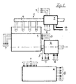
- FIG. 1 In the schematic illustration of FIG. 1 is as an internal combustion engine a diesel engine 1 shown in the drive train, a transmission unit 2 is downstream, and having an exhaust line 3, in the exhaust pipe 4 as a Rußabbrennfilter working Particle filter 5 is arranged. Further, a control device 6 illustrates this as a control and computer unit can be formed and in which, as indicated by the arrows, from the diesel engine 1, the transmission unit 2 and the Particle filter 5 detected measurement and control signals in control commands for the operation of engine 1, transmission unit 2, particle filter 5 and other not shown here elements of a not shown vehicle to be implemented, which in turn On the input side can be linked to the controller 6. The signals supplied to the control unit 6 are through the Arrows 7, the signals emitted by the control unit 6 by arrows 8 illustrates.
- the control unit 6 To the detected by the control unit 6 signals Among other things, it also includes a driven side Speed signal 9.
- the transmission unit 2 and the particulate filter 5 shown drive unit in particular still one in the exhaust system 3 lying exhaust gas turbocharger be integrated, and for example also a starter unit in the form of a starter-generator unit, the generator side depending on the Operating conditions of the vehicle is driven, in particular for example, in braking mode to the braking energy in implement electrical energy, as shown in the context of Solution according to the invention with electrical heating of the particulate filter as an additional consumer in elevated Dimensions needed.
- the relevant electrical connections of the particulate filter are symbolically indicated by +/-.
- the driving behavior can be controlled via the control unit 6 the driver of a respective vehicle characterizing Driving data and possibly also, in particular in connection with route guidance and traffic guidance systems, route profiles and to process data describing the traffic flow and in Implement control signals, such as in control signals for special gearshift programs as well as in the operation of the Particulate filter for soot combustion in coordination with the engine Operation controlling programs.
- This can be, for example also determine and implement control variables that the Rußabbrennung taking into account the amounts covered by past periods Control operating states.
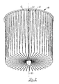
- the filter body 10 (Fig. 2) of filter bags 11 is constructed, which in triangular contour in at least one, preferably two wedge blades leak, which perpendicular to each other, adjoining edges associated with the filter bag 11.
- Fig. 2 the filter body 10 of filter bags 11 is constructed, which in triangular contour in at least one, preferably two wedge blades leak, which perpendicular to each other, adjoining edges associated with the filter bag 11.
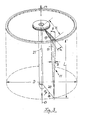
- the filter body 10 associated filter housing, against the filter body 10 in the embodiment via a peripheral edge 12 is supported, based on the raw gas inlet (arrow 13) and the clean gas side outflow (Arrow 14), in the region of the parting line, in particular the separation level assigned between the raw gas and clean gas side lies, wherein in the region of this parting plane, the pocket openings 15 of the filter bags 11 are, as shown in Fig. 3 erkenhbar.
- Fig. 2 shows that the filter body 10 from a Variety of filter bags 11 is constructed, with next to the illustrated rotationally symmetrical shape and oval shapes as well as partially retracted filter body shapes can be realized, the latter, for example, by different Sizes of the filter bags 11.
- the filter pockets 11 preferably have one with through openings provided support structure, for example, and preferably Expanded metal on which the porous, metallic filter surface is sintered.
- support structure for example, and preferably Expanded metal on which the porous, metallic filter surface is sintered.
- This may prove useful in particular surfaces of the support structure, so for example nodal surfaces of the expanded metal as loading areas for the or to provide the Schustrahler forming the heat source, so that these surfaces can form reflection surfaces in which Area a particularly intense heating of the soot coating takes place.
- corresponding areas for example by a roughened surface texture, also a experience particularly intense heating, so they 'glow points' from which the soot combustion progresses.
- a filter body 10 given that of about 50 (fifty) adjoining Filter bags 11 is constructed so that for this, based on the rotationally symmetrical structure, a radial outwardly opening wedge angle ⁇ - see Fig. 3 - of about 7 ° results.
- the axial pocket length is denoted by L and corresponds in the embodiment about twice the height H of Filter bag 11 or from the pocket opening 15. From this results itself a against the pocket opening 15 opening wedge angle ⁇ of about 3 to 4 °.
- the given in the pocket opening 15 Wedge back width B, and thus the width of the rear wall 17th the filter bag 11 in the region of the pocket opening 15 is approximately at the eighth part of the height H of the filter bag 11.
- particle filters operating with sootburning prove to be particularly useful in a configuration in which the filter pockets 11 are grouped around a center and are rotationally symmetric or oval in approach, the wedge-shaped filter pockets 11 wedge back widths B between 5 to 12 mm, preferably between 6 to 8 mm.
- This is particularly in connection with dimensions in which a filter body 10 is formed of filter pockets 11 with wedge back widths between 5 and 12 mm, in particular 6 to 8 mm, wherein the number n of the filter pockets 11 to the diameter D in mm of the filter body 10 in the range of 0.26 x D ⁇ n ⁇ 0.52 x D lies.
- a wedge angle ⁇ opening against the pocket opening 15 proves to be expedient, for which the following applies: 1 ° ⁇ ⁇ 4.5 °, and this in particular in conjunction with wedge filter pockets in which the wedge-back width B in FIG Area of the filter pocket opening 15 to the filter pocket length L in the following ratio: 10 ⁇ L / B ⁇ 80, especially 10 ⁇ L / B ⁇ 60.
- a determination of the total filter area F in relation to the maximum air mass m flowing over the filter body 10 proves to be expedient, for which the following applies: 200 ⁇ m / F ⁇ 350, wherein the air mass m in kg / h and the filter surface F in m 2 is detected.
- Such a is laid out particulate filter proves for charged vehicle diesel engines with a displacement of about 2,000 cm 3, a maximum mass air flow rate of 450 kg / h and a filter area of 1.7 m 2 to be particularly suitable, with about 60 filter bags 11 are provided, whose Length L is 250 mm, with a Wedge back width B of about 7 mm and a height H of about 60 mm.
- the filter bags 11 connected to a filter body 10 having a closed Core, so that the raw gas side flow can only be done axially and radially from the outside.
- embodiments are also included in the scope of the invention open core, for example, when supporting the filter bags in the dividing plane between raw gas side and clean gas side radial inside and outside, and with raw gas side support only radially outward, so that regardless of the radially inner junction the filter bags 11 also a certain flow resulting from the radially inner core region.
- the filter bags 11 also recognize that this opposite to her the triangular-shaped pocket opening 15th containing end face in a wedge-shaped end face 18 converge, and that also the back wall 17 opposite Long side quasi forms a wedge edge, in the the side walls 20 converge.
- the filter bag 11 In view on the side walls 20, the filter bag 11 has a rectangular shape.
- FIGS. 4, 6, 8 and 10 each show a view of a side wall 20, only their against the opening plane of the filter bags 11 expiring partial length is shown.
- This one Part length corresponding length range of the filter bag 11 in Fig. 2 is symbolized by the arrow 21.
- this length range of the filter bag 11 about half Length L of the filter bag or is less than half Length L of the filter bag 11.
- FIGS. 5, 7, 9 and 11 each symbolize the top view between two adjacent filter bags 11 and show greatly simplifies the location of the particular as a radiator non-contact on the respective side walls 20 and the rear walls 17 acting heating elements 22, in the embodiment 4 and 5 by heating rods 23, in particular Flatness rods 23 are formed.
- the heating elements 23 are, for Illustrating, in an indicated housing 24 of the particulate filter 5, so that the power supply from outside the housing 24 and thus can be protected, as by the lines 25 symbolizes.
- the heating rods 23 protrude respectively limited in the adjacent filter bags 11 Counter space 26 inside, which is in accordance with the wedge shape of Filter bags 11, in the opposite direction, d. H.
- FIGS. 6 and 7 A corresponding embodiment is also shown in FIGS. 6 and 7, being provided here as a heating element 22, a heating coil 28 is, with otherwise the same structure as in Figs. 4 and 5, respectively the local description.
- Figs. 8 and 9 illustrate further embodiments of heating elements 22, wherein a heating element in the form of a surface radiator 29 is provided which extends in the longitudinal direction of the filter bags 11 extends in the trapped by these counter space 26, wherein for the sake of simplicity, here too a radial energy supply is provided via lines 30, if necessary with a corresponding radial support. Not shown is that also a longitudinally extending Holder is within the scope of the invention.
- a heating source 22 as a radial Spotlight 31, in contrast to the surface 29th is not in the counter space 26, or immersed in this, but the circumference of the filter body 10, in particular the rear wall 17 is arranged opposite a filter bag 11 and for the rear wall 17 substantially the irradiated area forms, where also the arrangement shown with respect to the length L of the respective filter bag 11 is only illustrative whose purpose is that the heating to ignite the Soot in particular in the expiring on the filter bags 15 Longitudinal region of the filter body 10 takes place.
- FIG. 10 A corresponding circumferential loading preferably with associated with the region of the rear wall of the filter bags 11, this opposite and oriented to this heat source 22 shows FIG. 10, wherein the heating source 22 in this case each formed by a rod-shaped radiator 33, in In contrast to the embodiment of the radiator 31 in FIGS. 8 and 9, which is designed as a point-like heat source, for example in analogy to a point-like heating source formed by a laser. Illustrated in both FIGS. 8 and 9 as well as in the Fig.
- a reflector 34 may be assigned to the bundling of the respective radiation, at the same time to shield the housing 24, and optionally also in an embodiment, which is not shown here is, as a guide body for the inflowing against the filter pockets 11 Raw gas, the formation of this guide both the protection of the heat source 22 against the direct admission Serve with soot particles, as well as the focus formation with regard to the soot loading of the filter bag in the irradiation area the respective heat source 22.
- Activated is the respective heat source 22 in the inventive Solution preferred only for a short time, about for a period of up to 3 minutes, and then there is the further Rußabbrennung by progression of an incandescent or flame front in the Soot.
- the addressed, ignition and / or separation promoting measures to vote on the firing period or period of the firing, in particular, the burning over such measures ultimately also be controlled.
- the combustion be superimposed on promotional measures, such as the heating of the raw gases on the measures already mentioned internal engine kind or also the increase of the oxygen portion through additional air supply.
- promotional measures such as the heating of the raw gases on the measures already mentioned internal engine kind or also the increase of the oxygen portion through additional air supply.
- In appropriate Way is a bias in the opposite direction to the slowdown or to terminate the respective burning process possible, also in this regard combinations of the individual measures, those in the claims, as in some cases in the previous Description in detail are possible, possible and are appropriate.
- the total area acted upon by radiation area the total filter area is according to the invention 0.5 to 30%, in particular at 0.5 to 10% of the total filter surface, so that the total by electrical heating introduced, the Soot igniting energy only on a small to very small part of the filter surface acts, with correspondingly high Power density with low energy consumption.
- the back walls 17 of a portion of the filter bags 11 as irradiated Serve areas and in this case the total by Radiation hit area fraction only at 0.1 to 10%, especially at up to 4% of all through the back walls 17 Filter pockets 11 of the filter body 10 formed circumferentially Filter surface is located.
Landscapes
- Chemical & Material Sciences (AREA)
- Engineering & Computer Science (AREA)
- Chemical Kinetics & Catalysis (AREA)
- Combustion & Propulsion (AREA)
- Mechanical Engineering (AREA)
- General Engineering & Computer Science (AREA)
- Geometry (AREA)
- Physics & Mathematics (AREA)
- Life Sciences & Earth Sciences (AREA)
- Geology (AREA)
- Textile Engineering (AREA)
- Filtering Of Dispersed Particles In Gases (AREA)
- Processes For Solid Components From Exhaust (AREA)
- Filtering Materials (AREA)
Applications Claiming Priority (7)
| Application Number | Priority Date | Filing Date | Title |
|---|---|---|---|
| DE10128936A DE10128936A1 (de) | 2001-06-18 | 2001-06-18 | Partikelfilter, insbesondere für Abgase von Dieselbrennkraftmaschinen |
| DE10128936 | 2001-06-18 | ||
| DE10128938 | 2001-06-18 | ||
| DE10128938A DE10128938A1 (de) | 2001-06-18 | 2001-06-18 | Verfahren zum Abtrennen von Rußpartikeln in Partikelfiltern, und Partikelfilter hierzu |
| DE10223452A DE10223452A1 (de) | 2002-05-25 | 2002-05-25 | Partikelfilter für Abgase von Brennkraftmaschinen |
| DE10223452 | 2002-05-25 | ||
| PCT/EP2002/006724 WO2002102493A2 (de) | 2001-06-18 | 2002-06-18 | Mit russabbrennung arbeitender partikelfilter für dieselmotoren |
Publications (2)
| Publication Number | Publication Date |
|---|---|
| EP1399239A2 EP1399239A2 (de) | 2004-03-24 |
| EP1399239B1 true EP1399239B1 (de) | 2005-03-16 |
Family
ID=27214474
Family Applications (1)
| Application Number | Title | Priority Date | Filing Date |
|---|---|---|---|
| EP02762292A Expired - Lifetime EP1399239B1 (de) | 2001-06-18 | 2002-06-18 | Mit russabbrennung arbeitender partikelfilter für dieselmotoren |
Country Status (7)
| Country | Link |
|---|---|
| US (1) | US7029510B2 (enExample) |
| EP (1) | EP1399239B1 (enExample) |
| JP (1) | JP4060858B2 (enExample) |
| BR (1) | BR0210472B1 (enExample) |
| DE (1) | DE50202490D1 (enExample) |
| ES (1) | ES2240790T3 (enExample) |
| WO (1) | WO2002102493A2 (enExample) |
Families Citing this family (9)
| Publication number | Priority date | Publication date | Assignee | Title |
|---|---|---|---|---|
| DE10328188A1 (de) * | 2003-06-24 | 2005-01-13 | Robert Bosch Gmbh | Partikelfilter, insbesondere für Abgase von Brennkraftmaschinen |
| US20100170211A1 (en) * | 2007-04-11 | 2010-07-08 | Mann+Hummel Gmbh | Intake Air Cleaner |
| US7950222B2 (en) * | 2007-07-27 | 2011-05-31 | Cummins, Inc. | System and method for cleaning combustion soot from exhaust gas treatment sensors |
| US8083839B2 (en) * | 2007-09-13 | 2011-12-27 | GM Global Technology Operations LLC | Radiant zone heated particulate filter |
| US8444729B2 (en) * | 2007-11-26 | 2013-05-21 | Caterpillar Inc. | Electrically regenerated exhaust particulate filter having non-axial regeneration flame propagation |
| US7981174B2 (en) * | 2007-11-26 | 2011-07-19 | Caterpillar Inc. | Electrically regenerated exhaust particulate filter for an engine system and operating strategy therefor |
| DE102008014528A1 (de) * | 2008-03-15 | 2009-09-17 | Hjs Fahrzeugtechnik Gmbh & Co. Kg | Verfahren zum Bestimmen des Beladungszustandes eines in den Abgasstrang einer Brennkraftmaschine eingeschalteten Partikelfilters sowie Einrichtung zum Reduzieren der Partikelemission einer Brennkraftmaschine |
| US9371754B2 (en) * | 2009-03-12 | 2016-06-21 | Caterpillar Inc. | Diesel particulate filter regeneration control and method |
| DE102010013990A1 (de) | 2010-04-07 | 2011-10-13 | Emitec Gesellschaft Für Emissionstechnologie Mbh | Verfahren und Abgasbehandlungsvorrichtung zur Regeneration einer Abgasreinigungskomponente |
Family Cites Families (29)
| Publication number | Priority date | Publication date | Assignee | Title |
|---|---|---|---|---|
| DE7529340U (de) * | 1975-09-17 | 1976-02-19 | Freudenberg Carl Fa , 6940 Weinheim | Gasfilterelement |
| CH608976A5 (enExample) | 1976-06-04 | 1979-02-15 | Luwa Ag | |
| US4359864A (en) * | 1981-02-05 | 1982-11-23 | Caterpillar Tractor Co. | Burn-out type cleaning means for particulate filter of engine exhaust system |
| JPS5937224A (ja) * | 1982-08-24 | 1984-02-29 | Ngk Spark Plug Co Ltd | 可燃性微粒子除去用フイルタ装置 |
| US4562039A (en) | 1984-06-27 | 1985-12-31 | Pall Corporation | Porous metal article and method of making |
| US4641496A (en) * | 1984-12-17 | 1987-02-10 | Ford Motor Company | Continuous rotary regeneration system for a particulate trap |
| DE3608801A1 (de) | 1986-03-15 | 1987-09-17 | Fev Forsch Energietech Verbr | Verfahren und vorrichtung zur regeneration von partikelfiltersystemen |
| DE3637516C1 (en) * | 1986-11-04 | 1988-04-14 | Intensiv Filter Gmbh | Filter elements for dust filters |
| DE3723544A1 (de) | 1987-07-16 | 1989-01-26 | Man Technologie Gmbh | Elektrostatischer filter zum reinigen von gasen |
| JPH0353041Y2 (enExample) | 1987-08-31 | 1991-11-19 | ||
| DE3821143A1 (de) | 1987-09-04 | 1989-03-16 | Mann & Hummel Filter | Verfahren und vorrichtung zum abbrennen von auf einem abgasfilter abgeschiedenem russ |
| DE3807539A1 (de) | 1988-03-08 | 1989-09-21 | Peter Voelskow | Russfilter |
| DE3838589C1 (enExample) * | 1988-11-14 | 1989-12-28 | Voest-Alpine Automotive Ges.M.B.H., Linz, At | |
| DE9010910U1 (de) | 1990-07-23 | 1990-10-25 | Electrostar Schöttle GmbH & Co, 7313 Reichenbach | Rohrartiger Filter |
| JPH04179818A (ja) | 1990-11-14 | 1992-06-26 | Nippon Soken Inc | 排気ガス微粒子浄化装置 |
| US5259190A (en) * | 1991-08-01 | 1993-11-09 | Corning Incorporated | Heated cellular structures |
| DE4223277C2 (de) | 1992-07-15 | 2001-07-19 | Linde Ag | Verfahren und Vorrichtung zur Partikelentfernung aus Abgasen von Brennkraftmaschinen |
| DE4243990A1 (de) | 1992-12-23 | 1994-07-07 | Magnet Motor Gmbh | Kraftfahrzeug, insbesondere Stadtbus, mit Dieselmotor/Generator-Einheit |
| DE4403450C1 (de) | 1994-02-04 | 1995-04-06 | Freudenberg Carl Fa | Wechselrahmen |
| EP0707139B1 (en) * | 1994-10-13 | 2000-01-19 | Sumitomo Electric Industries, Ltd. | Particulate trap |
| DE19503067C2 (de) | 1995-02-01 | 1997-07-10 | Mtu Friedrichshafen Gmbh | Abgasfilter zur Beseitigung von Partikeln aus dem Abgas eines Dieselmotors |
| JPH08229330A (ja) * | 1995-02-28 | 1996-09-10 | Sumitomo Electric Ind Ltd | ディーゼルエンジン用パティキュレートトラップ |
| DE19520146C1 (de) | 1995-06-01 | 1996-06-27 | Braun Ag | Verfahren zur Herstellung von porösen Körpern und ihre Verwendung |
| JPH09187614A (ja) * | 1996-01-12 | 1997-07-22 | Toyoda Spinning & Weaving Co Ltd | フィルタエレメント |
| US5782941A (en) * | 1996-09-23 | 1998-07-21 | Sumitomo Electric Industries, Ltd. | Particulate trap for diesel engine |
| JPH10121941A (ja) * | 1996-10-18 | 1998-05-12 | Sumitomo Electric Ind Ltd | 排気ガス浄化装置 |
| JPH10176519A (ja) | 1996-12-18 | 1998-06-30 | Sumitomo Electric Ind Ltd | ディーゼルエンジン用パティキュレートトラップ |
| DE19810738C1 (de) | 1998-03-12 | 1999-04-22 | Hjs Fahrzeugtechnik Gmbh & Co | Einrichtung zum Reinigen von Abgasen eines Dieselmotors |
| DE19855092B4 (de) | 1998-11-28 | 2007-11-29 | Volkswagen Ag | Vorrichtung und Verfahren zum Reinigen des Abgases einer Brennkraftmaschine |
-
2002
- 2002-06-18 JP JP2004553539A patent/JP4060858B2/ja not_active Expired - Fee Related
- 2002-06-18 DE DE50202490T patent/DE50202490D1/de not_active Expired - Lifetime
- 2002-06-18 ES ES02762292T patent/ES2240790T3/es not_active Expired - Lifetime
- 2002-06-18 EP EP02762292A patent/EP1399239B1/de not_active Expired - Lifetime
- 2002-06-18 BR BRPI0210472-5A patent/BR0210472B1/pt not_active IP Right Cessation
- 2002-06-18 WO PCT/EP2002/006724 patent/WO2002102493A2/de not_active Ceased
-
2003
- 2003-12-18 US US10/739,786 patent/US7029510B2/en not_active Expired - Lifetime
Also Published As
| Publication number | Publication date |
|---|---|
| DE50202490D1 (de) | 2005-04-21 |
| BR0210472B1 (pt) | 2010-06-01 |
| WO2002102493A2 (de) | 2002-12-27 |
| WO2002102493A8 (de) | 2003-12-31 |
| US20040128960A1 (en) | 2004-07-08 |
| ES2240790T3 (es) | 2005-10-16 |
| JP2005520098A (ja) | 2005-07-07 |
| BR0210472A (pt) | 2004-08-10 |
| US7029510B2 (en) | 2006-04-18 |
| WO2002102493A3 (de) | 2003-05-01 |
| EP1399239A2 (de) | 2004-03-24 |
| JP4060858B2 (ja) | 2008-03-12 |
Similar Documents
| Publication | Publication Date | Title |
|---|---|---|
| EP1212521B1 (de) | Vorrichtung mit heizelement zur abgasreinigung | |
| DE69701649T2 (de) | Abgasreiniger | |
| EP2014883B1 (de) | Vorrichtung zur Reinigung von Abgasen | |
| DE3874924T2 (de) | Diesel-abgas-partikelfilter. | |
| EP1801372B1 (de) | Partikelfilteranordnung und Verfahren zum Filtern von Abgasen | |
| DE3734197C2 (enExample) | ||
| DE69428380T2 (de) | Honigwabenheizgerät | |
| EP0892887A1 (de) | Hitzebeständiger und regenerierbarer filterkörper mit strömungswegen | |
| DE3403564A1 (de) | Filtriereinrichtung zum entfernen oxidierbarer partikel aus dem abgas eines dieselmotors | |
| EP2557288A1 (de) | Vorrichtung und Verfahren zur Abgasreinigung für Verbrennungskraftmaschinen | |
| EP1399239B1 (de) | Mit russabbrennung arbeitender partikelfilter für dieselmotoren | |
| DE4035971A1 (de) | Beheizbare katalysatoranordnung fuer die abgasreinigung von verbrennungsmotoren | |
| DE69325188T2 (de) | Katalytische abgasreinigungsvorrichtung und katalytisches verfahren zur abgasreinigung | |
| DE3919343A1 (de) | Dieselrussfilter mit sich bei teillast verringerndem aktivem querschnitt | |
| DE60125204T2 (de) | Verfahren und vorrichtung zur behandlung eines gasstroms | |
| DE19835565A1 (de) | Vorrichtung zur Nachbehandlung von Motorabgasen eines Dieselmotors | |
| EP2166203A1 (de) | Vorrichtung zur Reinigung eines Abgasstroms einer Brennkraftmaschine eines Kraftfahrzeuges, insbesondere eines Nutzfahrzeuges | |
| DE19855092B4 (de) | Vorrichtung und Verfahren zum Reinigen des Abgases einer Brennkraftmaschine | |
| EP1304455B1 (de) | Partikelfilter zum Reinigen von motorischen Abgasen | |
| CH678751A5 (enExample) | ||
| EP0442318B1 (de) | Durch Abbrennen regenerierbarer Partikelfilter für die Abgase von Brennkraftmaschinen | |
| EP0638776A1 (de) | Verfahren zur Verringerung der Geruchs - und Schadstoffemission bei Heizgeräten für Fahrzeuge und Anordnung zur Durchführung des Verfahrens | |
| WO2000008310A1 (de) | Vorrichtung und verfahren zur nachbehandlung der motorabgase einer brennkraftmaschine | |
| DE102023106514A1 (de) | Elektrisches Widerstands-Heizeinheit sowie damit ausgestattetes Rauchgas-Behandlungsmodul | |
| DE102006041284B4 (de) | Verfahren und Vorrichtung zum thermischen Regenerieren von durchströmten Parikelfiltern |
Legal Events
| Date | Code | Title | Description |
|---|---|---|---|
| PUAI | Public reference made under article 153(3) epc to a published international application that has entered the european phase |
Free format text: ORIGINAL CODE: 0009012 |
|
| 17P | Request for examination filed |
Effective date: 20040116 |
|
| AK | Designated contracting states |
Kind code of ref document: A2 Designated state(s): AT BE CH CY DE DK ES FI FR GB GR IE IT LI LU MC NL PT SE TR |
|
| GRAP | Despatch of communication of intention to grant a patent |
Free format text: ORIGINAL CODE: EPIDOSNIGR1 |
|
| GRAS | Grant fee paid |
Free format text: ORIGINAL CODE: EPIDOSNIGR3 |
|
| GRAA | (expected) grant |
Free format text: ORIGINAL CODE: 0009210 |
|
| AK | Designated contracting states |
Kind code of ref document: B1 Designated state(s): DE ES FR GB IT |
|
| REG | Reference to a national code |
Ref country code: GB Ref legal event code: FG4D Free format text: NOT ENGLISH |
|
| REG | Reference to a national code |
Ref country code: IE Ref legal event code: FG4D Free format text: GERMAN |
|
| REF | Corresponds to: |
Ref document number: 50202490 Country of ref document: DE Date of ref document: 20050421 Kind code of ref document: P |
|
| GBT | Gb: translation of ep patent filed (gb section 77(6)(a)/1977) |
Effective date: 20050519 |
|
| REG | Reference to a national code |
Ref country code: ES Ref legal event code: FG2A Ref document number: 2240790 Country of ref document: ES Kind code of ref document: T3 |
|
| PLBE | No opposition filed within time limit |
Free format text: ORIGINAL CODE: 0009261 |
|
| STAA | Information on the status of an ep patent application or granted ep patent |
Free format text: STATUS: NO OPPOSITION FILED WITHIN TIME LIMIT |
|
| ET | Fr: translation filed | ||
| 26N | No opposition filed |
Effective date: 20051219 |
|
| REG | Reference to a national code |
Ref country code: DE Ref legal event code: R081 Ref document number: 50202490 Country of ref document: DE Owner name: HJS EMISSION TECHNOLOGY GMBH & CO. KG, DE Free format text: FORMER OWNER: HJS FAHRZEUGTECHNIK GMBH & CO, 58706 MENDEN, DE Effective date: 20110201 |
|
| REG | Reference to a national code |
Ref country code: FR Ref legal event code: PLFP Year of fee payment: 14 |
|
| REG | Reference to a national code |
Ref country code: FR Ref legal event code: PLFP Year of fee payment: 15 |
|
| REG | Reference to a national code |
Ref country code: FR Ref legal event code: PLFP Year of fee payment: 16 |
|
| REG | Reference to a national code |
Ref country code: FR Ref legal event code: PLFP Year of fee payment: 17 |
|
| PGFP | Annual fee paid to national office [announced via postgrant information from national office to epo] |
Ref country code: FR Payment date: 20180622 Year of fee payment: 17 |
|
| PGFP | Annual fee paid to national office [announced via postgrant information from national office to epo] |
Ref country code: GB Payment date: 20180403 Year of fee payment: 17 Ref country code: ES Payment date: 20180720 Year of fee payment: 17 Ref country code: IT Payment date: 20180629 Year of fee payment: 17 Ref country code: DE Payment date: 20180625 Year of fee payment: 17 |
|
| REG | Reference to a national code |
Ref country code: DE Ref legal event code: R119 Ref document number: 50202490 Country of ref document: DE |
|
| GBPC | Gb: european patent ceased through non-payment of renewal fee |
Effective date: 20190618 |
|
| PG25 | Lapsed in a contracting state [announced via postgrant information from national office to epo] |
Ref country code: DE Free format text: LAPSE BECAUSE OF NON-PAYMENT OF DUE FEES Effective date: 20200101 Ref country code: IT Free format text: LAPSE BECAUSE OF NON-PAYMENT OF DUE FEES Effective date: 20190618 Ref country code: GB Free format text: LAPSE BECAUSE OF NON-PAYMENT OF DUE FEES Effective date: 20190618 |
|
| PG25 | Lapsed in a contracting state [announced via postgrant information from national office to epo] |
Ref country code: FR Free format text: LAPSE BECAUSE OF NON-PAYMENT OF DUE FEES Effective date: 20190630 |
|
| REG | Reference to a national code |
Ref country code: ES Ref legal event code: FD2A Effective date: 20201028 |
|
| PG25 | Lapsed in a contracting state [announced via postgrant information from national office to epo] |
Ref country code: ES Free format text: LAPSE BECAUSE OF NON-PAYMENT OF DUE FEES Effective date: 20190619 |