EP1398567A2 - Cowl for smoke extraction - Google Patents
Cowl for smoke extraction Download PDFInfo
- Publication number
- EP1398567A2 EP1398567A2 EP03077912A EP03077912A EP1398567A2 EP 1398567 A2 EP1398567 A2 EP 1398567A2 EP 03077912 A EP03077912 A EP 03077912A EP 03077912 A EP03077912 A EP 03077912A EP 1398567 A2 EP1398567 A2 EP 1398567A2
- Authority
- EP
- European Patent Office
- Prior art keywords
- static vacuum
- vacuum cleaner
- cleaner device
- bands
- internal
- Prior art date
- Legal status (The legal status is an assumption and is not a legal conclusion. Google has not performed a legal analysis and makes no representation as to the accuracy of the status listed.)
- Withdrawn
Links
Images


Classifications
-
- F—MECHANICAL ENGINEERING; LIGHTING; HEATING; WEAPONS; BLASTING
- F23—COMBUSTION APPARATUS; COMBUSTION PROCESSES
- F23L—SUPPLYING AIR OR NON-COMBUSTIBLE LIQUIDS OR GASES TO COMBUSTION APPARATUS IN GENERAL ; VALVES OR DAMPERS SPECIALLY ADAPTED FOR CONTROLLING AIR SUPPLY OR DRAUGHT IN COMBUSTION APPARATUS; INDUCING DRAUGHT IN COMBUSTION APPARATUS; TOPS FOR CHIMNEYS OR VENTILATING SHAFTS; TERMINALS FOR FLUES
- F23L17/00—Inducing draught; Tops for chimneys or ventilating shafts; Terminals for flues
- F23L17/02—Tops for chimneys or ventilating shafts; Terminals for flues
- F23L17/12—Devices for fastening the top or terminal to chimney, shaft, or flue
-
- F—MECHANICAL ENGINEERING; LIGHTING; HEATING; WEAPONS; BLASTING
- F23—COMBUSTION APPARATUS; COMBUSTION PROCESSES
- F23J—REMOVAL OR TREATMENT OF COMBUSTION PRODUCTS OR COMBUSTION RESIDUES; FLUES
- F23J2213/00—Chimneys or flues
- F23J2213/30—Specific materials
- F23J2213/303—Specific materials metallic
Definitions
- the present invention relates to the technical sector of devices allowing or improving the extraction of ambient air from all types of rooms and combustible gases from all types of chimneys, stoves, boilers and this in a nonlimiting way including the septic tanks.
- each stage itself comprises at least two bands crossed at 90 °.
- a chimney extractor described in the document FR n ° 2231279 comprising stepped bands and crossing on a support nestable on the end part of a chimney flue.
- the strips define openings for the passage of smoke.
- the bands are flat.
- the support is equipped with elastically deformable fixing means.
- Static vacuums known from the prior art generally have parts involving complex manufacturing and use a complex and heavy structure. It is necessary to facilitate the installation of the devices, their implementation and to facilitate their handling. The manufacture of these systems must also be simplified while respecting the wish to limit the mechanical stresses (forces, vibrations, movement). Most of the known systems are especially ineffective in terms of "depression height", that is to say in terms of power or suction capacity. Note that in this area, each millimeter of depression gained represents significant progress.
- Table 1 below represents a control report of a gas boiler dated 09/10/02 showing a depression of only 0.06HPa, which corresponds to a depression representing only 10 -5 of the normal atmospheric pressure of 1030 HPa.
- Optimizing the millions of possible geometries is therefore a parameter that can create very small but qualitatively surprising quantitative effects, which can make the difference between good and bad print.
- the present invention relates to a device of the aforementioned type, the design was carried out in order to obtain a significant gain in height or vacuum column compared to known systems, including apparently similar geometry.
- This new design is based on a distinctly Venturi-type effect improved over the Venturi effect used in systems known in the art regardless of the wind direction.
- the present invention relates to a static vacuum device adaptable to any type of duct or bushel and allowing or improving the extraction of ambient air of all types of rooms and combustible gases of all types of fireplaces, stoves, boilers and this without limitation including septic tanks.
- the design of said static vacuum device according to the invention presents many advantages such as non-backdrafting of gases evacuated, improving the chimney draft and stabilizing the draft allowing more regular combustion and therefore saving energy.
- the design of said device also makes it possible to avoid entry volatiles inside the chimneys and ensures a watertightness of rain.
- Said static vacuum device comprises at least one "active element” (1), comprising external lateral bands (2), at least one "medium internal "(3), capable of creating a Venturi-type effect improved in cooperation with said active element (1) and a connecting piece (4), adaptable to all types of new or renovated bushels (BO) and intended to connect the assembly formed by said active element (1) and said internal means (3) to said bushel (BO), and to bring the gas to be extracted or "gaseous fluid" (FG) into the interior of said internal means (3), and from there to the exterior (EXT) via the element active (1).
- active element comprising external lateral bands (2), at least one "medium internal "(3), capable of creating a Venturi-type effect improved in cooperation with said active element (1) and a connecting piece (4), adaptable to all types of new or renovated bushels (BO) and intended to connect the assembly formed by said active element (1) and said internal means (3) to said bushel (BO), and to bring the gas to be extracted or "gaseous fluid" (FG) into the interior of said internal means
- the present invention relates to a static vacuum device mounted on all types of chimneys and allowing to ventilate all types of premises including so-called "at risk” premises.
- Said static vacuum device comprises at least one "active element” (1) composed of 2, 4, or 6 (or more) external side bands (2), at least an "internal means” (3) capable of creating a Venturi-type effect improved by cooperation with said external lateral bands (2) and a piece of fitting (4) or support allowing the adaptation of said vacuum device static on any type of bushel (square or round geometry, sheathed or no, this without limitation) and intended to cause the gas to be extracted or "fluid gaseous "(FG) in the interior of said internal means (3), and from there to the exterior (EXT) via the active element (1).
- active element composed of 2, 4, or 6 (or more) external side bands (2)
- an "internal means” (3) capable of creating a Venturi-type effect improved by cooperation with said external lateral bands (2) and a piece of fitting (4) or support allowing the adaptation of said vacuum device static on any type of bushel (square or round geometry, sheathed or no, this without limitation) and intended to cause the gas to be extracted or "fluid
- the present invention allows the extraction of ambient air (FG) contained in the interior of any type of room (as non-limiting examples, we we can quote a workshop, a bathroom, a cellar, a cabin boat ...) as well as smoke or combustion gases from chimneys, stoves, of boiler, this in a nonlimiting way (“interior gaseous fluid (FG)”) y including septic tanks and allowing their effective discharge to the outside even in adverse weather conditions.
- FG ambient air
- Said "active element" (1) of said device is composed of 2, 4, or 6 (or more) outer side bands (2), preferably 4, intersecting in a preferred option in a top (5) and thus creating an interior volume (Vl) and able to provide substantially vertical O1 openings therebetween adapted to connect the outside air (AE) and the fluid gaseous (FG) from the inside, coming from the inside of said internal means (3), to ensure the extraction of this fluid and its rejection in the outside air using a Venturi-type effect.
- Said side bands (2) connect the top (5) of said device to the periphery of the connecting piece or support (4), the top (5) of the device static being formed by the plane central intersection zone of the bands outer side (2).
- Said "internal means” (3) capable of creating a Venturi-type effect by cooperation with the outer lateral bands (2) comprises at least one element (6,7) partially opened by at least one O2 opening in its upper part and extending vertically the connecting piece (4) from so as to bring the gaseous fluid (FG) into a zone called zone intermediate (Zl) of the interior volume (Vl) delimited by the lateral bands exterior (2).
- a depression is created at the level of at least one of said openings O2 of said internal means (3) cooperating with said openings O1 of the active element (1) allowing the extraction of the fluid gas (FG) and its release into the outside air according to a Venturi-type effect improved.
- FIG. 1 very schematically represents the means and the characteristics of the device according to the invention.
- said static vacuum device comprises an "active element” (1) composed of external lateral bands (2), an “internal means” (3) capable of creating an effect Venturi type in cooperation with said outer side bands in an intermediate zone (Zl) and a connecting piece (4) or support allowing the adaptation of said static vacuum device to any type of bushel (of square or round geometry, sheathed or not, this not for limiting).
- the outer lateral bands (2) are capable of creating O1 openings capable of cooperating, in the intermediate zone (Zl), with the O2 openings of the internal means (3), forming a Venturi system improved between said openings O1 and O2.
- the active element (1) is composed of 4 external side bands (2) arranged at 90 ° to each other others.
- said means capable of creating a Venturi effect by cooperation with said external lateral bands (2) is a system with crossed interior bands (6), preferably 4 bands, intersecting preferably to each other at 90 °, able to create O2 openings substantially vertical at the intermediate zone (Zl) and positioned to cooperate with the outer side bands (2) of the active element (1).
- Said crossed interior side bands (6) are fixed on the periphery of the connecting piece (4) so that extend it to bring the gaseous fluid (FG) from the inside in the intermediate zone (Zl) of the interior volume Vl delimited by the bands outer side (2).
- said internal crossed bands (6) constituting the internal means form a system angularly offset from the system formed by the outer side bands (2).
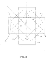
- the best mode is a system of 4 outer side bands (2) crossed at 90 ° from each other, and a system of 4 crossed bands interior (6), this second internal system being angularly offset by 45 ° compared to the first external system ( Figure 3).
- the means capable of creating a Venturi-type effect in cooperation with the external lateral bands (2) is a turret of internal square geometry (7) constituting the internal means and vertically extending the piece of fitting (4), open at the top and comprising at least one opening lateral O2 substantially vertical at the intermediate zone (Zl) of geometry such that an increase in area of the opening exists between the base of the opening and the top of the opening.
- This O2 opening can have, by way of example, without limitation, a triangle or trapezoid shape or analogues, "point down".
- said opening of said turret of square geometry (7) can be of triangular geometry pierced holes and "tip down" respecting an open surface capable of ensuring the Venturi effect.
- the latter option has the advantage of being effective against the birds.
- the square turret (7) has a lateral opening 02 in "V" cut at the top of each side of the turret.
- the support or connecting piece (4) is provided at its lower end with a square piece (10) adapted to the plug and having a hole (11) of variable diameter in its center allowing the guidance and positioning of a casing by compared to the device according to the invention.
- Said O2 openings of said internal means in the form of a square turret (7) are able to cooperate with the openings O1 formed by the strips lateral lateral (2) at the intermediate zone (Zl).
- said "internal means" (3) comprises possibly a second internal means allowing to fluidize the extraction gaseous fluid.
- Said fluidization means (8) can be a suitable aerodynamic profile to decrease the pressure drop of the gaseous fluid and increase the column of depression.
- This second internal means (8) cooperates with said first internal means (3) capable of creating a Venturi effect in cooperation with the active element (1).
- said fluidization means can be, without limitation, an inverted cone, an inverted pyramid with a base square or polygonal, "tip down", and the like.
- the fluidization means (8) with the square geometry turret (7) is fixed by its base on the flat central intersection area or "vertex" (5) of the lateral bands outside, and its pointed lower part then enters the part superior of the first internal means (in this case preferably, said "square turret” (7)) substantially up to the level of the intermediate zone (ZI).
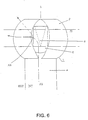
- FIG. 6 combines the fluidification means (8) with the creation means of Venturi in the form of interior crossed side bands (6).
- Said means of fluidization (8) with aerodynamic profile is fixed by its base on the area plane central intersection of the interior lateral bands, and its part the more pointed is found substantially at the intermediate zone (Zl).
- substantially vertical is meant throughout the present application y understood the claims, that the openings O1 and O2 are mainly open at the intermediate zone (Zl) (even if their (s) end (s) in the vertical direction is / are above and / or below the intermediate zone (Zl)), and that the general direction of these openings is vertical.
- O1 globally forms an oval
- its major axis is vertical.
- O2 is a triangle
- its point is at the bottom and the corresponding base is at the top
- the ends upper and lower may be outside the intermediate zone (Zl).
- the connecting piece (4) of the device static vacuum can be adjustable in height by using all adjustment means such as for example, without limitation, systems telescopic sleeves fitting into each other, sliding systems, ring and sleeve systems and all analogs having the same function.
- the fluidization means (8) of the flow of the gaseous fluid can also be adjustable by any means to adjust its vertical positioning relative to the top (5) such as for example, without limitation, a screw located at its base, or any analogous means having the same function, and which can be adjusted from from the top (5) of the device.
- the means (3) capable of creating an effect of Venturi in cooperation with the outer side bands (2) could be replaced by a molded plastic bulb, the point of which softening would be greater than 300 ° C, having at least one system substantially vertical side slits having the function of O2 openings.
- the connecting piece (4) or else called support can be round or square geometry, or square geometry in its upper part and round geometry in its part lower, this without limitation.
- the outer lateral bands (2) in the case of a connecting piece (4) or square geometry support can form at their fixings at the periphery of said connecting piece or support, fins (9) providing a stop for translational movement vertical allowing their fixing and the adaptation of the device in any type of bushel.
- the outer lateral bands (2) forming said "active element" (1) are the same width over their entire length.
- the crossed interior bands (6) are the same width than the outer side bands (2).
- the width of the side bands (2) is around 29% minimum and around 33% maximum width of the square turret (7).
- the active element of the present invention has a height of 2/5 of the total height of the device full.
- the part located between the lower end of the active element (1) and the upper part of the bushel is 1/5 of the total height and the part recessed of the device between the lower end and the upper end of the bushel represents 2/5 of the height.
- the fluidizing means (8) of aerodynamic shape has a diameter at its base or a base diagonal in the case a square base which represents 2/3 of the diameter of the active element (1), and its height is of the order of twice the radius of curvature of the strips outer side (2).
- the square turret (7) and its extension by the part square of support in the plug must have a minimum height of three times the dimension on the bushel side, breaking down as follows: 2/5 inside the bushel, 1/5 from the stop of the bushel at the bottom of the active element (1) and 2/5 for the height of the active element (1).
- the connecting piece (4) has a roller burnishing allowing its nesting as well as its maintenance in all types of bushels.
- all the elements making up the vacuum device of the present invention are spot welded and are made of stainless material and generally in all types of materials compatible with the envisaged application, in particular in stainless steel, plastics of sufficient softening point and the like and assembled by all types of assembly means.
- the shape of the support pieces of the system of the present invention is less complex manufacturing compared to systems known to date, and avoids the addition of a spacer by a spot welding process.
- the invention also covers all the embodiments and all the applications that will be directly accessible to those skilled in the art at the reading of this request, of his own knowledge.
- a prototype device according to the invention was subjected to a test of comparative performance with devices certified according to standard NF P50-413.
- Said certified devices are grouped into class A and class B.
- Class A represents a device with the lowest heights of depression, thus exhibiting poor smoke extraction.
- Class B represents a device with very good heights of depression, therefore exhibiting very good smoke extraction.
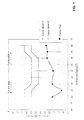
- Figure 7 shows the performance graph resulting from this test comparative.
- the curves obtained reflect the heights of depression for each of the categories. Generally speaking, the higher the depression factor is negative, the better the extraction.
- the first curve is obtained with reference to class A devices
- the second curve is obtained with reference to class B devices
- the third curve is obtained with a prototype device according to the present invention.
- the performance graph thus obtained shows that the device according to the invention is clearly more efficient than all the devices certified according to standard NF P50-413.
Landscapes
- Engineering & Computer Science (AREA)
- Chemical & Material Sciences (AREA)
- Combustion & Propulsion (AREA)
- Mechanical Engineering (AREA)
- General Engineering & Computer Science (AREA)
- Jet Pumps And Other Pumps (AREA)
- Working Measures On Existing Buildindgs (AREA)
Abstract
Description
La présente invention concerne le secteur technique des dispositifs permettant ou améliorant l'extraction de l'air ambiant de tous types de salles et des gaz combustibles de tous types de cheminées, poêles, chaudières et ceci de manière non limitative y compris les fosses septiques.The present invention relates to the technical sector of devices allowing or improving the extraction of ambient air from all types of rooms and combustible gases from all types of chimneys, stoves, boilers and this in a nonlimiting way including the septic tanks.
On connaít un extracteur pour cheminée décrit dans le document FR n°1556262 comprenant des bandes en tôles cintrées et étagées de manière à constituer un premier étage intérieur et un second étage extérieur concentriques, associées à un support emboítable sur la partie terminale libre d'un conduit de cheminée. Selon l'une des nombreuses versions décrites sans préférence, chaque étage comprend lui-même au moins deux bandes croisées à 90°.We know a chimney extractor described in the document FR n ° 1556262 comprising strips of curved and stepped sheets to constitute an interior first stage and an exterior second stage concentric, associated with a nestable support on the free terminal part a chimney flue. According to one of the many versions described without preference, each stage itself comprises at least two bands crossed at 90 °.
On connaít également un extracteur pour cheminée décrit dans le document FR n°2231279 comprenant des bandes étagées et se croisant sur un support emboítable sur la partie terminale d'un conduit de cheminée. Les bandes définissent des ouvertures pour le passage de la fumée. Dans la zone de croisement, les bandes sont planes. Le support est équipé de moyens de fixation élastiquement déformables. We also know a chimney extractor described in the document FR n ° 2231279 comprising stepped bands and crossing on a support nestable on the end part of a chimney flue. The strips define openings for the passage of smoke. In the crossing zone, the bands are flat. The support is equipped with elastically deformable fixing means.
Les aspirateurs statiques connus de l'art antérieur possèdent généralement
des pièces impliquant une fabrication complexe et mettent en oeuvre une
structure complexe et lourde.
Il est nécessaire de faciliter la pose des dispositifs, leur mise en oeuvre et de
faciliter leur manutention.
La fabrication de ces systèmes doit également être simplifiée tout en
respectant le souhait de limiter les contraintes mécaniques (efforts, vibrations,
mouvement).
La plupart des systèmes connus sont surtout peu efficaces en termes de
"hauteur de dépression" c'est-à-dire en termes de puissance ou de capacité
d'aspiration.
On notera que dans ce domaine, chaque millimètre de dépression gagné
représente un progrès important. Le tableau 1 ci-dessous représente un
rapport de contrôle d'une chaudière à gaz daté du 10/09/02 montrant une
dépression de seulement 0,06HPa, ce qui correspond à une dépression
représentant seulement 10-5 de la pression atmosphérique normale de 1030
HPa. L'optimisation des millions de géométries possibles est donc un
paramètre pouvant créer des effets quantitatifs très faibles mais
qualitativement surprenants, pouvant faire la différence entre un bon et un
mauvais tirage.
gaz liqu. propane
Mesuré selon le Règlement Fédéral sur la Protection des Emissions
It is necessary to facilitate the installation of the devices, their implementation and to facilitate their handling.
The manufacture of these systems must also be simplified while respecting the wish to limit the mechanical stresses (forces, vibrations, movement).
Most of the known systems are especially ineffective in terms of "depression height", that is to say in terms of power or suction capacity.
Note that in this area, each millimeter of depression gained represents significant progress. Table 1 below represents a control report of a gas boiler dated 09/10/02 showing a depression of only 0.06HPa, which corresponds to a depression representing only 10 -5 of the normal atmospheric pressure of 1030 HPa. Optimizing the millions of possible geometries is therefore a parameter that can create very small but qualitatively surprising quantitative effects, which can make the difference between good and bad print.
gas liqu. propane
Measured according to the Federal Emission Protection Regulations
La présente invention concerne un dispositif du type précité, dont la conception a été effectuée afin d'obtenir un gain significatif en hauteur ou colonne de dépression par rapport aux systèmes connus, y compris de géométrie apparemment voisine.The present invention relates to a device of the aforementioned type, the design was carried out in order to obtain a significant gain in height or vacuum column compared to known systems, including apparently similar geometry.
Cette nouvelle conception repose sur un effet de type Venturi nettement amélioré par rapport à l'effet Venturi utilisé dans les systèmes connus de l'art antérieur, et ce, quelle que soit la direction du vent.This new design is based on a distinctly Venturi-type effect improved over the Venturi effect used in systems known in the art regardless of the wind direction.
La présente invention concerne un dispositif aspirateur statique adaptable à tout type de conduit ou boisseau et permettant ou améliorant l'extraction de l'air ambiant de tous types de salles et des gaz combustibles de tous types de cheminées, poêles, chaudières et ceci de manière non limitative y compris les fosses septiques.The present invention relates to a static vacuum device adaptable to any type of duct or bushel and allowing or improving the extraction of ambient air of all types of rooms and combustible gases of all types of fireplaces, stoves, boilers and this without limitation including septic tanks.
La conception dudit dispositif aspirateur statique selon l'invention présente de nombreux avantages tels que le non-refoulement par le vent des gaz évacués, l'amélioration du tirage de la cheminée ainsi que la stabilisation du tirage permettant une combustion plus régulière et donc une économie d'énergie. La conception dudit dispositif permet également d'éviter l'entrée des volatiles à l'intérieur des cheminées et assure une étanchéité à l'eau de pluie.The design of said static vacuum device according to the invention presents many advantages such as non-backdrafting of gases evacuated, improving the chimney draft and stabilizing the draft allowing more regular combustion and therefore saving energy. The design of said device also makes it possible to avoid entry volatiles inside the chimneys and ensures a watertightness of rain.
Ledit dispositif aspirateur statique comprend au moins un "élément actif' (1), comportant des bandes latérales extérieures (2), au moins un "moyen interne" (3), apte à créer un effet de type Venturi amélioré en coopération avec ledit élément actif (1) et une pièce de raccord (4), adaptable à tous types de boisseaux neufs ou rénovés (BO) et destinée à raccorder l'ensemble formé par ledit élément actif (1) et ledit moyen interne (3) audit boisseau (BO), et à amener le gaz à extraire ou 'fluide gazeux" (FG) dans l'intérieur dudit moyen interne (3), et de là vers l'extérieur (EXT) via l'élément actif (1).Said static vacuum device comprises at least one "active element" (1), comprising external lateral bands (2), at least one "medium internal "(3), capable of creating a Venturi-type effect improved in cooperation with said active element (1) and a connecting piece (4), adaptable to all types of new or renovated bushels (BO) and intended to connect the assembly formed by said active element (1) and said internal means (3) to said bushel (BO), and to bring the gas to be extracted or "gaseous fluid" (FG) into the interior of said internal means (3), and from there to the exterior (EXT) via the element active (1).
Ledit dispositif et son principe de fonctionnement seront mieux compris à la lecture de la description qui va suivre. Said device and its operating principle will be better understood on reading of the description which will follow.
La présente invention concerne un dispositif aspirateur statique se montant sur tous types de cheminées et permettant de ventiler tous types de locaux y compris les locaux dits "à risques".The present invention relates to a static vacuum device mounted on all types of chimneys and allowing to ventilate all types of premises including so-called "at risk" premises.
Ledit dispositif aspirateur statique comprend au moins un "élément actif' (1) composé de 2, 4, ou 6 (ou plus) bandes latérales extérieures (2), au moins un "moyen interne"(3) apte à créer un effet de type Venturi amélioré en coopération avec lesdites bandes latérales extérieures (2) et une pièce de raccord (4) ou support permettant l'adaptation dudit dispositif aspirateur statique sur tout type de boisseau (de géométrie carrée ou ronde, gainé ou non, ceci à titre non limitatif) et destinée à amener le gaz à extraire ou "fluide gazeux" (FG) dans l'intérieur dudit moyen interne (3), et de là vers l'extérieur (EXT) via l'élément actif (1).Said static vacuum device comprises at least one "active element" (1) composed of 2, 4, or 6 (or more) external side bands (2), at least an "internal means" (3) capable of creating a Venturi-type effect improved by cooperation with said external lateral bands (2) and a piece of fitting (4) or support allowing the adaptation of said vacuum device static on any type of bushel (square or round geometry, sheathed or no, this without limitation) and intended to cause the gas to be extracted or "fluid gaseous "(FG) in the interior of said internal means (3), and from there to the exterior (EXT) via the active element (1).
La présente invention permet l'extraction de l'air ambiant (FG) contenu à l'intérieur de tout type de salle (comme exemples non limitatifs, nous pouvons citer un atelier, une salle de bain, une cave, une cabine de bateau...) ainsi que la fumée ou gaz de combustion de cheminée, de poêle, de chaudière, ceci de manière non limitative (''fluide gazeux (FG) intérieur") y compris les fosses septiques et permettant leur rejet efficace vers l'extérieur même en conditions atmosphériques défavorables.The present invention allows the extraction of ambient air (FG) contained in the interior of any type of room (as non-limiting examples, we we can quote a workshop, a bathroom, a cellar, a cabin boat ...) as well as smoke or combustion gases from chimneys, stoves, of boiler, this in a nonlimiting way ("interior gaseous fluid (FG)") y including septic tanks and allowing their effective discharge to the outside even in adverse weather conditions.
Ledit "élément actif" (1) dudit dispositif est composé de 2, 4, ou 6 (ou plus) bandes latérales extérieures (2), de préférence 4, se croisant selon une option préférée en un sommet (5) et créant ainsi un volume intérieur (Vl) et aptes à ménager entre elles des ouvertures O1 sensiblement verticales adaptées pour mettre en communication l'air extérieur (AE) et le fluide gazeux (FG) de l'intérieur, provenant de l'intérieur dudit moyen interne (3), afin d'assurer l'extraction de ce fluide et son rejet dans l'air extérieur à l'aide d'un effet de type Venturi.Said "active element" (1) of said device is composed of 2, 4, or 6 (or more) outer side bands (2), preferably 4, intersecting in a preferred option in a top (5) and thus creating an interior volume (Vl) and able to provide substantially vertical O1 openings therebetween adapted to connect the outside air (AE) and the fluid gaseous (FG) from the inside, coming from the inside of said internal means (3), to ensure the extraction of this fluid and its rejection in the outside air using a Venturi-type effect.
Lesdites bandes latérales (2) relient le sommet (5) dudit dispositif à la périphérie de la pièce de raccord ou support (4), le sommet (5) du dispositif statique étant formé par la zone d'intersection centrale plane des bandes latérales extérieures (2).Said side bands (2) connect the top (5) of said device to the periphery of the connecting piece or support (4), the top (5) of the device static being formed by the plane central intersection zone of the bands outer side (2).
Ledit "moyen interne" (3) apte à créer un effet de type Venturi en coopération avec les bandes latérales extérieures (2) comporte au moins un élément (6,7) partiellement ouvert par au moins une ouverture O2 dans sa partie supérieure et prolongeant verticalement la pièce de raccord (4) de manière à amener le fluide gazeux (FG) dans une zone dite zone intermédiaire (Zl) du volume intérieur (Vl) délimité par les bandes latérales extérieures (2).Said "internal means" (3) capable of creating a Venturi-type effect by cooperation with the outer lateral bands (2) comprises at least one element (6,7) partially opened by at least one O2 opening in its upper part and extending vertically the connecting piece (4) from so as to bring the gaseous fluid (FG) into a zone called zone intermediate (Zl) of the interior volume (Vl) delimited by the lateral bands exterior (2).
Quelle que soit la direction du vent, une dépression se crée au niveau d'au moins une desdites ouvertures O2 dudit moyen interne (3) coopérant avec lesdites ouvertures O1 de l'élément actif (1) permettant l'extraction du fluide gazeux (FG) et son rejet dans l'air extérieur selon un effet de type Venturi amélioré.Whatever the wind direction, a depression is created at the level of at least one of said openings O2 of said internal means (3) cooperating with said openings O1 of the active element (1) allowing the extraction of the fluid gas (FG) and its release into the outside air according to a Venturi-type effect improved.
D'autres caractéristiques et avantages de la présente invention seront mieux
compris à la lecture de la description qui va suivre, et en se référant aux
dessins annexés sur lesquels:
La figure 1 représente de manière très schématique les moyens et les caractéristiques du dispositif selon l'invention. On voit sur la figure 1 que ledit dispositif aspirateur statique comprend un "élément actif" (1) composé de bandes latérales extérieures (2), un "moyen interne" (3) apte à créer un effet de type Venturi en coopération avec lesdites bandes latérales extérieures dans une zone intermédiaire (Zl) et une pièce de raccord (4) ou support permettant l'adaptation dudit dispositif aspirateur statique sur tout type de boisseau (de géométrie carrée ou ronde, gainé ou non, ceci à titre non limitatif).FIG. 1 very schematically represents the means and the characteristics of the device according to the invention. We see in Figure 1 that said static vacuum device comprises an "active element" (1) composed of external lateral bands (2), an "internal means" (3) capable of creating an effect Venturi type in cooperation with said outer side bands in an intermediate zone (Zl) and a connecting piece (4) or support allowing the adaptation of said static vacuum device to any type of bushel (of square or round geometry, sheathed or not, this not for limiting).
On voit que les bandes latérales extérieures (2) sont aptes à créer des ouvertures O1 capables de coopérer, dans la zone intermédiaire (Zl), avec les ouvertures O2 du moyen interne (3), en formant un système Venturi amélioré entre lesdites ouvertures O1 et O2. It can be seen that the outer lateral bands (2) are capable of creating O1 openings capable of cooperating, in the intermediate zone (Zl), with the O2 openings of the internal means (3), forming a Venturi system improved between said openings O1 and O2.
Selon un mode de réalisation préféré et non limitatif, l'élément actif (1) est composé de 4 bandes latérales extérieures (2) disposées à 90 ° les unes des autres.According to a preferred and nonlimiting embodiment, the active element (1) is composed of 4 external side bands (2) arranged at 90 ° to each other others.
De manière préférée, ledit moyen apte à créer un effet de Venturi en coopération avec lesdites bandes latérales extérieures(2), est un système à bandes intérieures croisées (6), de préférence 4 bandes, se croisant de préférence l'une à l'autre à 90°, aptes à créer des ouvertures O2 sensiblement verticales au niveau de la zone intermédiaire (Zl) et positionnées de manière à coopérer avec les bandes latérales extérieures (2) de l'élément actif (1). Lesdites bandes latérales intérieures (6) croisées sont fixées sur la périphérie de la pièce de raccord (4) de manière à prolonger cette dernière afin d'amener le fluide gazeux (FG) de l'intérieur dans la zone intermédiaire (Zl) du volume intérieur Vl délimité par les bandes latérales extérieures (2).Preferably, said means capable of creating a Venturi effect by cooperation with said external lateral bands (2), is a system with crossed interior bands (6), preferably 4 bands, intersecting preferably to each other at 90 °, able to create O2 openings substantially vertical at the intermediate zone (Zl) and positioned to cooperate with the outer side bands (2) of the active element (1). Said crossed interior side bands (6) are fixed on the periphery of the connecting piece (4) so that extend it to bring the gaseous fluid (FG) from the inside in the intermediate zone (Zl) of the interior volume Vl delimited by the bands outer side (2).
Selon un autre mode de réalisation préféré représenté par les figures 2 et 3, lesdites bandes croisées intérieures (6) constituant le moyen interne forment un système décalé angulairement par rapport au système formé par les bandes latérales extérieures (2).According to another preferred embodiment represented by FIGS. 2 and 3, said internal crossed bands (6) constituting the internal means form a system angularly offset from the system formed by the outer side bands (2).
Le meilleur mode est un système de 4 bandes latérales extérieures (2) croisées à 90° l'une de l'autre, et un système de 4 bandes croisées intérieures (6), ce second système interne étant décalé angulairement de 45° par rapport au premier système extérieur (figure 3).The best mode is a system of 4 outer side bands (2) crossed at 90 ° from each other, and a system of 4 crossed bands interior (6), this second internal system being angularly offset by 45 ° compared to the first external system (Figure 3).
Selon un autre mode de réalisation préféré représenté par les figures 4 et 5, le moyen apte à créer un effet de type Venturi en coopération avec les bandes latérales extérieures (2), est une tourelle de géométrie carrée interne (7) constituant le moyen interne et prolongeant verticalement la pièce de raccord (4), ouverte au sommet et comprenant au moins une ouverture latérale O2 sensiblement verticale au niveau de la zone intermédiaire (Zl) de géométrie telle qu'une augmentation de surface de l'ouverture existe entre la base de l'ouverture et le haut de l'ouverture. Cette ouverture O2 peut avoir, à titre d'exemple, non limitatif, une forme de triangle ou de trapèze ou analogues, "pointe en bas".According to another preferred embodiment represented by FIGS. 4 and 5, the means capable of creating a Venturi-type effect in cooperation with the external lateral bands (2), is a turret of internal square geometry (7) constituting the internal means and vertically extending the piece of fitting (4), open at the top and comprising at least one opening lateral O2 substantially vertical at the intermediate zone (Zl) of geometry such that an increase in area of the opening exists between the base of the opening and the top of the opening. This O2 opening can have, by way of example, without limitation, a triangle or trapezoid shape or analogues, "point down".
Selon un autre mode de réalisation, non limitatif, ladite ouverture de ladite tourelle de géométrie carrée (7) peut être de géométrie triangulaire percée de trous et "pointe en bas" en respectant une surface ouverte apte à assurer l'effet de Venturi. Cette dernière option a pour avantage d'être efficace contre les volatiles.According to another nonlimiting embodiment, said opening of said turret of square geometry (7) can be of triangular geometry pierced holes and "tip down" respecting an open surface capable of ensuring the Venturi effect. The latter option has the advantage of being effective against the birds.
De préférence, la tourelle carrée (7) comporte une ouverture latérale 02 en
"V" découpée dans la partie supérieure de chaque face de la tourelle.Preferably, the square turret (7) has a
Selon un mode de réalisation préféré représenté en figure 4, le support ou pièce de raccord (4) est muni en son extrémité inférieure d'une pièce carrée (10) adaptée au boisseau et présentant un trou (11) de diamètre variable en son centre permettant le guidage et le positionnement d'un tubage par rapport au dispositif selon l'invention.According to a preferred embodiment represented in FIG. 4, the support or connecting piece (4) is provided at its lower end with a square piece (10) adapted to the plug and having a hole (11) of variable diameter in its center allowing the guidance and positioning of a casing by compared to the device according to the invention.
Lesdites ouvertures O2 dudit moyen interne sous forme de tourelle carrée (7) sont aptes à coopérer avec les ouvertures O1 formées par les bandes latérales extérieures (2) au niveau de la zone intermédiaire (Zl).Said O2 openings of said internal means in the form of a square turret (7) are able to cooperate with the openings O1 formed by the strips lateral lateral (2) at the intermediate zone (Zl).
Selon un mode de réalisation préféré, ledit "moyen interne" (3) comprend éventuellement un second moyen interne permettant de fluidifier l'extraction du fluide gazeux.According to a preferred embodiment, said "internal means" (3) comprises possibly a second internal means allowing to fluidize the extraction gaseous fluid.
Ledit moyen de fluidification (8) peut être un profil aérodynamique adapté pour diminuer les pertes de charge du fluide gazeux et augmenter la colonne de dépression. Ce second moyen interne (8) coopère avec ledit premier moyen interne (3) apte à créer un effet de Venturi en coopération avec l'élément actif (1).Said fluidization means (8) can be a suitable aerodynamic profile to decrease the pressure drop of the gaseous fluid and increase the column of depression. This second internal means (8) cooperates with said first internal means (3) capable of creating a Venturi effect in cooperation with the active element (1).
Selon un autre mode de réalisation préféré, ledit moyen de fluidification peut être, à titre non limitatif, un cône inversé, une pyramide inversée à base carrée ou à base polygonale, "pointe en bas", et analogues. According to another preferred embodiment, said fluidization means can be, without limitation, an inverted cone, an inverted pyramid with a base square or polygonal, "tip down", and the like.
Selon un autre mode de réalisation préféré et selon la figure 5, on combine le moyen de fluidification (8) avec la tourelle de géométrie carrée (7). Ledit moyen de fluidification (8) à profil aérodynamique est fixé par sa base sur la zone d'intersection centrale plane ou "sommet" (5) des bandes latérales extérieures, et sa partie inférieure pointue pénètre alors dans la partie supérieure du premier moyen interne (dans ce cas de préférence, ladite "tourelle carrée" (7) ) sensiblement jusqu'au niveau de la zone intermédiaire (ZI).According to another preferred embodiment and according to FIG. 5, the fluidization means (8) with the square geometry turret (7). said fluidizing means (8) with aerodynamic profile is fixed by its base on the flat central intersection area or "vertex" (5) of the lateral bands outside, and its pointed lower part then enters the part superior of the first internal means (in this case preferably, said "square turret" (7)) substantially up to the level of the intermediate zone (ZI).
Selon un autre mode de réalisation ici préféré représenté en figure 6, on combine le moyen de fluidification (8) avec le moyen de création de Venturi sous forme de bandes latérales croisées intérieures (6). Ledit moyen de fluidification (8) à profil aérodynamique est fixé par sa base sur la zone d'intersection centrale plane des bandes latérales intérieures, et sa partie la plus pointue se trouve sensiblement au niveau de la zone intermédiaire (Zl).According to another preferred embodiment shown here in FIG. 6, combines the fluidification means (8) with the creation means of Venturi in the form of interior crossed side bands (6). Said means of fluidization (8) with aerodynamic profile is fixed by its base on the area plane central intersection of the interior lateral bands, and its part the more pointed is found substantially at the intermediate zone (Zl).
L'homme de métier aura compris que l'invention vise à créer une mise en
contact du fluide gazeux (FG) à extraire, avec l'air extérieur, dans la zone
intermédiaire (Zl) par coopération de type Venturi entre
Par "sensiblement verticales" on entend dans toute la présente demande y compris les revendications, que les ouvertures O1 et O2 sont principalement ouvertes au niveau de la zone intermédiaire (Zl) (même si leur(s) extrémité(s) dans le sens vertical est/sont au-dessus et/ou en-dessous de la zone intermédiaire (Zl)), et que la direction générale de ces ouvertures est verticale. Par exemple, si O1 forme globalement un ovale, son grand axe est vertical. Par exemple encore, si O2 est un triangle, sa pointe est en bas et la base correspondante est en haut Dans les deux cas, les extrémités supérieures et inférieures peuvent être hors de la zone intermédiaire (Zl).By "substantially vertical" is meant throughout the present application y understood the claims, that the openings O1 and O2 are mainly open at the intermediate zone (Zl) (even if their (s) end (s) in the vertical direction is / are above and / or below the intermediate zone (Zl)), and that the general direction of these openings is vertical. For example, if O1 globally forms an oval, its major axis is vertical. For example again, if O2 is a triangle, its point is at the bottom and the corresponding base is at the top In both cases, the ends upper and lower may be outside the intermediate zone (Zl).
Selon un autre mode de réalisation, la pièce de raccord (4) du dispositif aspirateur statique peut être réglable en hauteur par utilisation de tous moyens de réglage tels que par exemples, à titre non limitatif, des systèmes téléscopiques à manchons s'emboítant les uns dans les autres, des systèmes de coulissement, des systèmes de bagues et de manchons et tous analogues présentant la même fonction.According to another embodiment, the connecting piece (4) of the device static vacuum can be adjustable in height by using all adjustment means such as for example, without limitation, systems telescopic sleeves fitting into each other, sliding systems, ring and sleeve systems and all analogs having the same function.
Selon un autre mode de réalisation, le moyen de fluidification (8) de l'écoulement du fluide gazeux peut être également réglable par tout moyen permettant de régler son positionnement vertical par rapport au sommet (5) comme par exemple, à titre non limitatif, une vis située à sa base, ou tout moyen analogue présentant la même fonction, et pouvant être réglé à partir du sommet (5) du dispositif.According to another embodiment, the fluidization means (8) of the flow of the gaseous fluid can also be adjustable by any means to adjust its vertical positioning relative to the top (5) such as for example, without limitation, a screw located at its base, or any analogous means having the same function, and which can be adjusted from from the top (5) of the device.
Selon un autre mode de réalisation, le moyen (3) apte à créer un effet de Venturi en coopération avec les bandes latérales extérieures (2) pourrait être remplacé par un bulbe moulé en matière plastique, dont le point de ramollissement serait supérieur à 300 °C, possédant au moins un système de fentes latérales sensiblement verticales présentant la fonction des ouvertures O2.According to another embodiment, the means (3) capable of creating an effect of Venturi in cooperation with the outer side bands (2) could be replaced by a molded plastic bulb, the point of which softening would be greater than 300 ° C, having at least one system substantially vertical side slits having the function of O2 openings.
Selon un autre mode de réalisation, la pièce de raccord (4) ou encore appelée support peut être de géométrie ronde ou carrée, ou encore de géométrie carrée en sa partie supérieure et de géométrie ronde en sa partie inférieure, ceci à titre non limitatif.According to another embodiment, the connecting piece (4) or else called support can be round or square geometry, or square geometry in its upper part and round geometry in its part lower, this without limitation.
Selon un autre mode de réalisation, les bandes latérales extérieures (2) dans le cas d'une pièce de raccord (4) ou support de géométrie carrée peuvent former au niveau de leurs fixations à la périphérie de ladite pièce de raccord ou support, des ailettes (9) assurant une butée de mouvement de translation verticale permettant leur fixation et l'adaptation du dispositif dans tout type de boisseau.According to another embodiment, the outer lateral bands (2) in the case of a connecting piece (4) or square geometry support can form at their fixings at the periphery of said connecting piece or support, fins (9) providing a stop for translational movement vertical allowing their fixing and the adaptation of the device in any type of bushel.
De manière générale, les bandes latérales extérieures (2) formant ledit "élément actif" (1) sont de même largeur sur toute leur longueur.Generally, the outer lateral bands (2) forming said "active element" (1) are the same width over their entire length.
Selon un mode de réalisation préféré où le moyen interne comprend des bandes croisées (6), les bandes intérieures croisées (6) sont de même largeur que les bandes latérales extérieures (2).According to a preferred embodiment where the internal means comprises crossed bands (6), the crossed interior bands (6) are the same width than the outer side bands (2).
Selon un autre mode de réalisation préféré où le moyen interne est sous forme d'une tourelle carrée (7), la largeur des bandes latérales (2) est de l'ordre de 29% au minimum et de l'ordre de 33% au maximum de la largeur de la tourelle carrée (7).According to another preferred embodiment where the internal means is under shape of a square turret (7), the width of the side bands (2) is around 29% minimum and around 33% maximum width of the square turret (7).
Selon encore un mode de réalisation préféré, l'élément actif de la présente invention présente une hauteur de 2/5 de la hauteur totale du dispositif complet. La partie située entre l'extrémité inférieure de l'élément actif (1) et la partie supérieure du boisseau est de 1/5 de la hauteur totale et la partie encastrée du dispositif entre l'extrémité inférieure et l'extrémité supérieure du boisseau représente 2/5 de la hauteur.According to yet another preferred embodiment, the active element of the present invention has a height of 2/5 of the total height of the device full. The part located between the lower end of the active element (1) and the upper part of the bushel is 1/5 of the total height and the part recessed of the device between the lower end and the upper end of the bushel represents 2/5 of the height.
De manière préférée, le moyen de fluidification (8) de forme aérodynamique a un diamètre au niveau de sa base ou une diagonale de base dans le cas d'une base carrée qui représente les 2/3 du diamètre de l'élément actif (1), et sa hauteur est de l'ordre de deux fois le rayon de courbure des bandes latérales extérieures (2). Preferably, the fluidizing means (8) of aerodynamic shape has a diameter at its base or a base diagonal in the case a square base which represents 2/3 of the diameter of the active element (1), and its height is of the order of twice the radius of curvature of the strips outer side (2).
De manière préférée, la tourelle carrée (7) et son prolongement par la pièce carrée de support dans le boisseau doit avoir une hauteur minimum de trois fois la cote du côté du boisseau en se décomposant de la manière suivante: 2/5 à l'intérieur du boisseau, 1/5 depuis l'arrête du boisseau au bas de l'élément actif (1) et 2/5 pour la hauteur de l'élément actif (1).Preferably, the square turret (7) and its extension by the part square of support in the plug must have a minimum height of three times the dimension on the bushel side, breaking down as follows: 2/5 inside the bushel, 1/5 from the stop of the bushel at the bottom of the active element (1) and 2/5 for the height of the active element (1).
De manière préférée également la pièce de raccord (4) présente un galetage permettant son emboítement ainsi que son maintien dans tous types de boisseaux.Preferably also the connecting piece (4) has a roller burnishing allowing its nesting as well as its maintenance in all types of bushels.
De manière générale, tous les éléments composant le dispositif aspirateur statique de la présente invention sont soudés par point et sont fabriqués en matière inoxydable et de manière générale en tous types de matériaux compatibles avec l'application envisagée, notamment en acier inoxydable, matières plastiques de point de ramollissement suffisant et analogues et assemblés par tous types de moyens d'assemblage.In general, all the elements making up the vacuum device of the present invention are spot welded and are made of stainless material and generally in all types of materials compatible with the envisaged application, in particular in stainless steel, plastics of sufficient softening point and the like and assembled by all types of assembly means.
La forme des pièces d'appui du système de la présente invention est de fabrication moins complexe par rapport aux systèmes connus à ce jour, et évite l'adjonction d'une entretoise par un procédé de soudure par points.The shape of the support pieces of the system of the present invention is less complex manufacturing compared to systems known to date, and avoids the addition of a spacer by a spot welding process.
Malgré la simplification selon l'invention de la structure du dispositif aspirateur statique, toute désolidarisation des pièces due aux efforts extérieurs (vent, vibrations...) est évitée et on assure même un rendement supérieur par rapport à l'art antérieur.Despite the simplification according to the invention of the structure of the vacuum device static, any separation of the parts due to external forces (wind, vibrations ...) is avoided and even higher performance is ensured by compared to the prior art.
L'invention couvre également tous les modes de réalisation et toutes les applications qui seront directement accessibles à l'homme de métier à la lecture de la présente demande, de ses connaissances propres. The invention also covers all the embodiments and all the applications that will be directly accessible to those skilled in the art at the reading of this request, of his own knowledge.
Après essais, il s'avère que la combinaison de "l'élément actif" (1) formé de 4 bandes latérales extérieures (2) croisées à 90° et du "moyen interne" sous forme d'une tourelle carrée (7) possédant des ouvertures (O2) triangulaires donne des résultats supérieurs de 13 à 18% par rapport aux dispositifs fonctionnels antérieurs. La combinaison de "l'élément actif" (1) formé de 4 bandes latérales extérieures (2) croisées à 90° et du "moyen interne" sous forme de bandes intérieures croisées (6) donne des résultats supérieurs de 13 à 14% (on a sensiblement la même amélioration avec une adaptation ronde ou carrée) reflétant ainsi une meilleure colonne de dépression par rapport aux systèmes connus de l'art antérieur.After testing, it turns out that the combination of "active element" (1) formed of 4 external lateral bands (2) crossed at 90 ° and "internal means" under shape of a square turret (7) having triangular openings (O2) gives results that are 13 to 18% better than the devices previous functional. The combination of "active element" (1) formed of 4 external lateral bands (2) crossed at 90 ° and "internal means" under shape of crossed interior bands (6) gives superior results of 13 to 14% (we have substantially the same improvement with an adaptation round or square) thus reflecting a better vacuum column by compared to known systems of the prior art.
Egalement après essais, il s'avère que la combinaison de deux desdits moyens internes, dont ledit moyen à profil aérodynamique, de préférence ici un cône, permet une amélioration surprenante de la colonne de dépression de plus de 25% par rapport aux systèmes connus de l'art antérieur.Also after testing, it turns out that the combination of two of said internal means, including said aerodynamic profile means, preferably here a cone, allows a surprising improvement of the vacuum column more than 25% compared to known systems of the prior art.
Un dispositif prototype selon l'invention a été soumis à un test de performance comparatif avec des appareils certifiés selon la norme NF P50-413.A prototype device according to the invention was subjected to a test of comparative performance with devices certified according to standard NF P50-413.
Lesdits appareils certifiés sont regroupés en classe A et classe B.Said certified devices are grouped into class A and class B.
La classe A représente un appareil présentant les plus basses hauteurs de dépression, présentant ainsi une mauvaise extraction de fumées.Class A represents a device with the lowest heights of depression, thus exhibiting poor smoke extraction.
La classe B représente un appareil présentant de très bonnes hauteurs de dépression, présentant donc une très bonne extraction de fumées.Class B represents a device with very good heights of depression, therefore exhibiting very good smoke extraction.
La figure 7 représente le graphique de performance résultant de ce test comparatif. Les courbes obtenues reflètent les hauteurs de dépression pour chacune des catégories. De manière générale, plus le facteur de dépression est négatif, meilleure est l'extraction.Figure 7 shows the performance graph resulting from this test comparative. The curves obtained reflect the heights of depression for each of the categories. Generally speaking, the higher the depression factor is negative, the better the extraction.
La première courbe est obtenue en référence aux appareils de classe A, la deuxième courbe est obtenue en référence aux appareils de classe B et la troisième courbe est obtenue avec un dispositif prototype selon la présente invention.The first curve is obtained with reference to class A devices, the second curve is obtained with reference to class B devices and the third curve is obtained with a prototype device according to the present invention.
La comparaison des trois courbes montre que ledit dispositif prototype de la présente invention permet d'obtenir un meilleur facteur de dépression, c'est-à-dire un facteur de dépression négatif très bas par rapport à celui obtenu avec la classe B.The comparison of the three curves shows that said prototype device of the present invention makes it possible to obtain a better depression factor, that is to say a very low negative depression factor compared to that obtained with class B.
Le graphe de performance ainsi obtenu montre que le dispositif selon l'invention est nettement plus performant que l'ensemble des appareils certifiés selon la norme NF P50-413.The performance graph thus obtained shows that the device according to the invention is clearly more efficient than all the devices certified according to standard NF P50-413.
Claims (42)
Applications Claiming Priority (2)
| Application Number | Priority Date | Filing Date | Title |
|---|---|---|---|
| FR0211464A FR2844580B1 (en) | 2002-09-12 | 2002-09-12 | STATIC VACUUM DEVICE FOR EXTRACTING SMOKE |
| FR0211464 | 2002-09-12 |
Publications (2)
| Publication Number | Publication Date |
|---|---|
| EP1398567A2 true EP1398567A2 (en) | 2004-03-17 |
| EP1398567A3 EP1398567A3 (en) | 2004-04-21 |
Family
ID=31726068
Family Applications (1)
| Application Number | Title | Priority Date | Filing Date |
|---|---|---|---|
| EP03077912A Withdrawn EP1398567A3 (en) | 2002-09-12 | 2003-09-12 | Cowl for smoke extraction |
Country Status (2)
| Country | Link |
|---|---|
| EP (1) | EP1398567A3 (en) |
| FR (1) | FR2844580B1 (en) |
Cited By (2)
| Publication number | Priority date | Publication date | Assignee | Title |
|---|---|---|---|---|
| EP2369232A1 (en) * | 2010-03-23 | 2011-09-28 | Gilles Heissat | Device for protecting a smoke exhaust conduit against wind and/or rain, and corresponding cover |
| DE102010061527A1 (en) * | 2010-12-23 | 2012-06-28 | Peter Grelak | Chimney top cover for smoke outlet, has smoke outlet opening and portion that are bent from single material, where material is selected from stainless steel, and portion is attached on surface of chimney through attaching unit |
Citations (8)
| Publication number | Priority date | Publication date | Assignee | Title |
|---|---|---|---|---|
| GB477374A (en) * | 1936-06-29 | 1937-12-29 | John Blain Hunt | Improvements in or relating to air or smoke inducers |
| GB806319A (en) * | 1956-05-15 | 1958-12-23 | Oswald Dorrington Niblett | Improvements in or relating to ventilator and chimney cowls |
| FR1553122A (en) * | 1967-12-01 | 1969-01-10 | ||
| FR1556262A (en) * | 1967-11-27 | 1969-02-07 | ||
| US3523500A (en) * | 1968-10-14 | 1970-08-11 | Edward J Artis | Stationary chimney vacuum cap |
| US3826181A (en) * | 1972-06-09 | 1974-07-30 | G Schrade | Attachment for ventilating shafts or the like |
| FR2231279A5 (en) * | 1973-05-23 | 1974-12-20 | Rouquet Jean | Chimney cowl formed of crossed metal bands - ends of bands are attached to tube and bands are in contact in crossing zone |
| US4325291A (en) * | 1980-02-19 | 1982-04-20 | Improved Consumers Products, Inc. | Chimney cap and securement |
-
2002
- 2002-09-12 FR FR0211464A patent/FR2844580B1/en not_active Expired - Fee Related
-
2003
- 2003-09-12 EP EP03077912A patent/EP1398567A3/en not_active Withdrawn
Patent Citations (8)
| Publication number | Priority date | Publication date | Assignee | Title |
|---|---|---|---|---|
| GB477374A (en) * | 1936-06-29 | 1937-12-29 | John Blain Hunt | Improvements in or relating to air or smoke inducers |
| GB806319A (en) * | 1956-05-15 | 1958-12-23 | Oswald Dorrington Niblett | Improvements in or relating to ventilator and chimney cowls |
| FR1556262A (en) * | 1967-11-27 | 1969-02-07 | ||
| FR1553122A (en) * | 1967-12-01 | 1969-01-10 | ||
| US3523500A (en) * | 1968-10-14 | 1970-08-11 | Edward J Artis | Stationary chimney vacuum cap |
| US3826181A (en) * | 1972-06-09 | 1974-07-30 | G Schrade | Attachment for ventilating shafts or the like |
| FR2231279A5 (en) * | 1973-05-23 | 1974-12-20 | Rouquet Jean | Chimney cowl formed of crossed metal bands - ends of bands are attached to tube and bands are in contact in crossing zone |
| US4325291A (en) * | 1980-02-19 | 1982-04-20 | Improved Consumers Products, Inc. | Chimney cap and securement |
Cited By (3)
| Publication number | Priority date | Publication date | Assignee | Title |
|---|---|---|---|---|
| EP2369232A1 (en) * | 2010-03-23 | 2011-09-28 | Gilles Heissat | Device for protecting a smoke exhaust conduit against wind and/or rain, and corresponding cover |
| FR2958011A1 (en) * | 2010-03-23 | 2011-09-30 | Gilles Heissat | DEVICE FOR PROTECTING A WIND EXHAUST DUCT AGAINST THE EFFECTS OF WIND AND / OR RAIN, AND CORRESPONDING HAT |
| DE102010061527A1 (en) * | 2010-12-23 | 2012-06-28 | Peter Grelak | Chimney top cover for smoke outlet, has smoke outlet opening and portion that are bent from single material, where material is selected from stainless steel, and portion is attached on surface of chimney through attaching unit |
Also Published As
| Publication number | Publication date |
|---|---|
| FR2844580A1 (en) | 2004-03-19 |
| FR2844580B1 (en) | 2005-07-08 |
| EP1398567A3 (en) | 2004-04-21 |
Similar Documents
| Publication | Publication Date | Title |
|---|---|---|
| EP0641972B1 (en) | Static dynamic device for gaseous fluid removal | |
| EP1398567A2 (en) | Cowl for smoke extraction | |
| EP0972991B1 (en) | Static/dynamic gas extraction device | |
| FR2766014A1 (en) | LEAD ACID ACCUMULATOR, AND CLOSING AND FILTRATION ELEMENTS FOR SUCH AN ACCUMULATOR | |
| FR2658271A1 (en) | Device for sucking in and discharging gases or fumes and installation comprising a plurality of such devices | |
| FR2951809A1 (en) | Equipment for assuring passage of smoke evacuation pipe connected to e.g. mural condensation boiler in collective dwelling, has ventilation structure provided with passage for circulating air towards chimney flue liner | |
| EP0641973B1 (en) | Device for gaseous fluid removal | |
| EP0434577A1 (en) | Exhaust outlet with gas cleaner | |
| EP1520002A1 (en) | Device for lighting a fire | |
| EP0100692B1 (en) | Coupling for chimney pipes | |
| EP3372127A1 (en) | Cooking appliance with supply ramp | |
| EP0656513B1 (en) | Self regulating, non-return air inlet with acoustic roll, installation provided with such an air inlet | |
| EP1450101A1 (en) | Terminal duct for balanced flue | |
| EP0118647A1 (en) | Valve for a flushing tank | |
| FR2543265A1 (en) | Modular fireplace-protection device taking part in the extraction of the fumes and used as damper | |
| FR2855842A1 (en) | EXTREME HIGH AIR PERFORMANCE SMOKE EXTRACT SPECIFICALLY SUITABLE FOR CONSTRUCTION OR BUILDING ROOF VENTS | |
| FR3016430B1 (en) | STATIC EXTRACTOR FOR AIR EXHAUST OR AERATION DUCT | |
| FR2846073A1 (en) | Anti-flowback static smoke extractor comprises annular base, with curved upper face extended upwards by cylindrical flange, surmounted by cowl to delimit Venturi passage | |
| EP0421841A1 (en) | Apparatus for air circulation and installation containing such an apparatus | |
| FR2665050A1 (en) | Device for heating the ambient air around any crops | |
| FR2936299A1 (en) | PULSATORY BOILER WITH FLAP VALVE | |
| EP0878664A1 (en) | Gas injection device for inducing draught in a gaseous fluid transport system | |
| FR2890433A1 (en) | Windborne exhaust fan for gas or smoke evacuation conduit, has mobile part comprising walls and made of single metallic piece, where each wall is shaped and two adjacent walls are positioned such that openings are situated in radial plane | |
| BE628061A (en) | ||
| FR2814534A1 (en) | Wood stove for hot water production has front door for loading fuel, smoke exhaust pipe with damper and water tank in upper part of hearth |
Legal Events
| Date | Code | Title | Description |
|---|---|---|---|
| PUAI | Public reference made under article 153(3) epc to a published international application that has entered the european phase |
Free format text: ORIGINAL CODE: 0009012 |
|
| PUAL | Search report despatched |
Free format text: ORIGINAL CODE: 0009013 |
|
| AK | Designated contracting states |
Kind code of ref document: A2 Designated state(s): AT BE BG CH CY CZ DE DK EE ES FI FR GB GR HU IE IT LI LU MC NL PT RO SE SI SK TR |
|
| AX | Request for extension of the european patent |
Extension state: AL LT LV MK |
|
| AK | Designated contracting states |
Kind code of ref document: A3 Designated state(s): AT BE BG CH CY CZ DE DK EE ES FI FR GB GR HU IE IT LI LU MC NL PT RO SE SI SK TR |
|
| AX | Request for extension of the european patent |
Extension state: AL LT LV MK |
|
| RIC1 | Information provided on ipc code assigned before grant |
Ipc: 7F 23L 17/12 B Ipc: 7F 23L 17/02 A |
|
| AKX | Designation fees paid | ||
| REG | Reference to a national code |
Ref country code: DE Ref legal event code: 8566 |
|
| STAA | Information on the status of an ep patent application or granted ep patent |
Free format text: STATUS: THE APPLICATION IS DEEMED TO BE WITHDRAWN |
|
| 18D | Application deemed to be withdrawn |
Effective date: 20041022 |