EP1398567A2 - Schornsteinaufsatz zur Rauchgasabsaugung - Google Patents
Schornsteinaufsatz zur Rauchgasabsaugung Download PDFInfo
- Publication number
- EP1398567A2 EP1398567A2 EP03077912A EP03077912A EP1398567A2 EP 1398567 A2 EP1398567 A2 EP 1398567A2 EP 03077912 A EP03077912 A EP 03077912A EP 03077912 A EP03077912 A EP 03077912A EP 1398567 A2 EP1398567 A2 EP 1398567A2
- Authority
- EP
- European Patent Office
- Prior art keywords
- static vacuum
- vacuum cleaner
- cleaner device
- bands
- internal
- Prior art date
- Legal status (The legal status is an assumption and is not a legal conclusion. Google has not performed a legal analysis and makes no representation as to the accuracy of the status listed.)
- Withdrawn
Links
Images


Classifications
-
- F—MECHANICAL ENGINEERING; LIGHTING; HEATING; WEAPONS; BLASTING
- F23—COMBUSTION APPARATUS; COMBUSTION PROCESSES
- F23L—SUPPLYING AIR OR NON-COMBUSTIBLE LIQUIDS OR GASES TO COMBUSTION APPARATUS IN GENERAL ; VALVES OR DAMPERS SPECIALLY ADAPTED FOR CONTROLLING AIR SUPPLY OR DRAUGHT IN COMBUSTION APPARATUS; INDUCING DRAUGHT IN COMBUSTION APPARATUS; TOPS FOR CHIMNEYS OR VENTILATING SHAFTS; TERMINALS FOR FLUES
- F23L17/00—Inducing draught; Tops for chimneys or ventilating shafts; Terminals for flues
- F23L17/02—Tops for chimneys or ventilating shafts; Terminals for flues
- F23L17/12—Devices for fastening the top or terminal to chimney, shaft, or flue
-
- F—MECHANICAL ENGINEERING; LIGHTING; HEATING; WEAPONS; BLASTING
- F23—COMBUSTION APPARATUS; COMBUSTION PROCESSES
- F23J—REMOVAL OR TREATMENT OF COMBUSTION PRODUCTS OR COMBUSTION RESIDUES; FLUES
- F23J2213/00—Chimneys or flues
- F23J2213/30—Specific materials
- F23J2213/303—Specific materials metallic
Definitions
- the present invention relates to the technical sector of devices allowing or improving the extraction of ambient air from all types of rooms and combustible gases from all types of chimneys, stoves, boilers and this in a nonlimiting way including the septic tanks.
- each stage itself comprises at least two bands crossed at 90 °.
- a chimney extractor described in the document FR n ° 2231279 comprising stepped bands and crossing on a support nestable on the end part of a chimney flue.
- the strips define openings for the passage of smoke.
- the bands are flat.
- the support is equipped with elastically deformable fixing means.
- Static vacuums known from the prior art generally have parts involving complex manufacturing and use a complex and heavy structure. It is necessary to facilitate the installation of the devices, their implementation and to facilitate their handling. The manufacture of these systems must also be simplified while respecting the wish to limit the mechanical stresses (forces, vibrations, movement). Most of the known systems are especially ineffective in terms of "depression height", that is to say in terms of power or suction capacity. Note that in this area, each millimeter of depression gained represents significant progress.
- Table 1 below represents a control report of a gas boiler dated 09/10/02 showing a depression of only 0.06HPa, which corresponds to a depression representing only 10 -5 of the normal atmospheric pressure of 1030 HPa.
- Optimizing the millions of possible geometries is therefore a parameter that can create very small but qualitatively surprising quantitative effects, which can make the difference between good and bad print.
- the present invention relates to a device of the aforementioned type, the design was carried out in order to obtain a significant gain in height or vacuum column compared to known systems, including apparently similar geometry.
- This new design is based on a distinctly Venturi-type effect improved over the Venturi effect used in systems known in the art regardless of the wind direction.
- the present invention relates to a static vacuum device adaptable to any type of duct or bushel and allowing or improving the extraction of ambient air of all types of rooms and combustible gases of all types of fireplaces, stoves, boilers and this without limitation including septic tanks.
- the design of said static vacuum device according to the invention presents many advantages such as non-backdrafting of gases evacuated, improving the chimney draft and stabilizing the draft allowing more regular combustion and therefore saving energy.
- the design of said device also makes it possible to avoid entry volatiles inside the chimneys and ensures a watertightness of rain.
- Said static vacuum device comprises at least one "active element” (1), comprising external lateral bands (2), at least one "medium internal "(3), capable of creating a Venturi-type effect improved in cooperation with said active element (1) and a connecting piece (4), adaptable to all types of new or renovated bushels (BO) and intended to connect the assembly formed by said active element (1) and said internal means (3) to said bushel (BO), and to bring the gas to be extracted or "gaseous fluid" (FG) into the interior of said internal means (3), and from there to the exterior (EXT) via the element active (1).
- active element comprising external lateral bands (2), at least one "medium internal "(3), capable of creating a Venturi-type effect improved in cooperation with said active element (1) and a connecting piece (4), adaptable to all types of new or renovated bushels (BO) and intended to connect the assembly formed by said active element (1) and said internal means (3) to said bushel (BO), and to bring the gas to be extracted or "gaseous fluid" (FG) into the interior of said internal means
- the present invention relates to a static vacuum device mounted on all types of chimneys and allowing to ventilate all types of premises including so-called "at risk” premises.
- Said static vacuum device comprises at least one "active element” (1) composed of 2, 4, or 6 (or more) external side bands (2), at least an "internal means” (3) capable of creating a Venturi-type effect improved by cooperation with said external lateral bands (2) and a piece of fitting (4) or support allowing the adaptation of said vacuum device static on any type of bushel (square or round geometry, sheathed or no, this without limitation) and intended to cause the gas to be extracted or "fluid gaseous "(FG) in the interior of said internal means (3), and from there to the exterior (EXT) via the active element (1).
- active element composed of 2, 4, or 6 (or more) external side bands (2)
- an "internal means” (3) capable of creating a Venturi-type effect improved by cooperation with said external lateral bands (2) and a piece of fitting (4) or support allowing the adaptation of said vacuum device static on any type of bushel (square or round geometry, sheathed or no, this without limitation) and intended to cause the gas to be extracted or "fluid
- the present invention allows the extraction of ambient air (FG) contained in the interior of any type of room (as non-limiting examples, we we can quote a workshop, a bathroom, a cellar, a cabin boat ...) as well as smoke or combustion gases from chimneys, stoves, of boiler, this in a nonlimiting way (“interior gaseous fluid (FG)”) y including septic tanks and allowing their effective discharge to the outside even in adverse weather conditions.
- FG ambient air
- Said "active element" (1) of said device is composed of 2, 4, or 6 (or more) outer side bands (2), preferably 4, intersecting in a preferred option in a top (5) and thus creating an interior volume (Vl) and able to provide substantially vertical O1 openings therebetween adapted to connect the outside air (AE) and the fluid gaseous (FG) from the inside, coming from the inside of said internal means (3), to ensure the extraction of this fluid and its rejection in the outside air using a Venturi-type effect.
- Said side bands (2) connect the top (5) of said device to the periphery of the connecting piece or support (4), the top (5) of the device static being formed by the plane central intersection zone of the bands outer side (2).
- Said "internal means” (3) capable of creating a Venturi-type effect by cooperation with the outer lateral bands (2) comprises at least one element (6,7) partially opened by at least one O2 opening in its upper part and extending vertically the connecting piece (4) from so as to bring the gaseous fluid (FG) into a zone called zone intermediate (Zl) of the interior volume (Vl) delimited by the lateral bands exterior (2).
- a depression is created at the level of at least one of said openings O2 of said internal means (3) cooperating with said openings O1 of the active element (1) allowing the extraction of the fluid gas (FG) and its release into the outside air according to a Venturi-type effect improved.
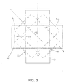
- FIG. 1 very schematically represents the means and the characteristics of the device according to the invention.
- said static vacuum device comprises an "active element” (1) composed of external lateral bands (2), an “internal means” (3) capable of creating an effect Venturi type in cooperation with said outer side bands in an intermediate zone (Zl) and a connecting piece (4) or support allowing the adaptation of said static vacuum device to any type of bushel (of square or round geometry, sheathed or not, this not for limiting).
- the outer lateral bands (2) are capable of creating O1 openings capable of cooperating, in the intermediate zone (Zl), with the O2 openings of the internal means (3), forming a Venturi system improved between said openings O1 and O2.
- the active element (1) is composed of 4 external side bands (2) arranged at 90 ° to each other others.
- said means capable of creating a Venturi effect by cooperation with said external lateral bands (2) is a system with crossed interior bands (6), preferably 4 bands, intersecting preferably to each other at 90 °, able to create O2 openings substantially vertical at the intermediate zone (Zl) and positioned to cooperate with the outer side bands (2) of the active element (1).
- Said crossed interior side bands (6) are fixed on the periphery of the connecting piece (4) so that extend it to bring the gaseous fluid (FG) from the inside in the intermediate zone (Zl) of the interior volume Vl delimited by the bands outer side (2).
- said internal crossed bands (6) constituting the internal means form a system angularly offset from the system formed by the outer side bands (2).
- the best mode is a system of 4 outer side bands (2) crossed at 90 ° from each other, and a system of 4 crossed bands interior (6), this second internal system being angularly offset by 45 ° compared to the first external system ( Figure 3).
- the means capable of creating a Venturi-type effect in cooperation with the external lateral bands (2) is a turret of internal square geometry (7) constituting the internal means and vertically extending the piece of fitting (4), open at the top and comprising at least one opening lateral O2 substantially vertical at the intermediate zone (Zl) of geometry such that an increase in area of the opening exists between the base of the opening and the top of the opening.
- This O2 opening can have, by way of example, without limitation, a triangle or trapezoid shape or analogues, "point down".
- said opening of said turret of square geometry (7) can be of triangular geometry pierced holes and "tip down" respecting an open surface capable of ensuring the Venturi effect.
- the latter option has the advantage of being effective against the birds.
- the square turret (7) has a lateral opening 02 in "V" cut at the top of each side of the turret.
- the support or connecting piece (4) is provided at its lower end with a square piece (10) adapted to the plug and having a hole (11) of variable diameter in its center allowing the guidance and positioning of a casing by compared to the device according to the invention.
- Said O2 openings of said internal means in the form of a square turret (7) are able to cooperate with the openings O1 formed by the strips lateral lateral (2) at the intermediate zone (Zl).
- said "internal means" (3) comprises possibly a second internal means allowing to fluidize the extraction gaseous fluid.
- Said fluidization means (8) can be a suitable aerodynamic profile to decrease the pressure drop of the gaseous fluid and increase the column of depression.
- This second internal means (8) cooperates with said first internal means (3) capable of creating a Venturi effect in cooperation with the active element (1).
- said fluidization means can be, without limitation, an inverted cone, an inverted pyramid with a base square or polygonal, "tip down", and the like.
- the fluidization means (8) with the square geometry turret (7) is fixed by its base on the flat central intersection area or "vertex" (5) of the lateral bands outside, and its pointed lower part then enters the part superior of the first internal means (in this case preferably, said "square turret” (7)) substantially up to the level of the intermediate zone (ZI).
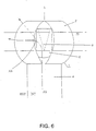
- FIG. 6 combines the fluidification means (8) with the creation means of Venturi in the form of interior crossed side bands (6).
- Said means of fluidization (8) with aerodynamic profile is fixed by its base on the area plane central intersection of the interior lateral bands, and its part the more pointed is found substantially at the intermediate zone (Zl).
- substantially vertical is meant throughout the present application y understood the claims, that the openings O1 and O2 are mainly open at the intermediate zone (Zl) (even if their (s) end (s) in the vertical direction is / are above and / or below the intermediate zone (Zl)), and that the general direction of these openings is vertical.
- O1 globally forms an oval
- its major axis is vertical.
- O2 is a triangle
- its point is at the bottom and the corresponding base is at the top
- the ends upper and lower may be outside the intermediate zone (Zl).
- the connecting piece (4) of the device static vacuum can be adjustable in height by using all adjustment means such as for example, without limitation, systems telescopic sleeves fitting into each other, sliding systems, ring and sleeve systems and all analogs having the same function.
- the fluidization means (8) of the flow of the gaseous fluid can also be adjustable by any means to adjust its vertical positioning relative to the top (5) such as for example, without limitation, a screw located at its base, or any analogous means having the same function, and which can be adjusted from from the top (5) of the device.
- the means (3) capable of creating an effect of Venturi in cooperation with the outer side bands (2) could be replaced by a molded plastic bulb, the point of which softening would be greater than 300 ° C, having at least one system substantially vertical side slits having the function of O2 openings.
- the connecting piece (4) or else called support can be round or square geometry, or square geometry in its upper part and round geometry in its part lower, this without limitation.
- the outer lateral bands (2) in the case of a connecting piece (4) or square geometry support can form at their fixings at the periphery of said connecting piece or support, fins (9) providing a stop for translational movement vertical allowing their fixing and the adaptation of the device in any type of bushel.
- the outer lateral bands (2) forming said "active element" (1) are the same width over their entire length.
- the crossed interior bands (6) are the same width than the outer side bands (2).
- the width of the side bands (2) is around 29% minimum and around 33% maximum width of the square turret (7).
- the active element of the present invention has a height of 2/5 of the total height of the device full.
- the part located between the lower end of the active element (1) and the upper part of the bushel is 1/5 of the total height and the part recessed of the device between the lower end and the upper end of the bushel represents 2/5 of the height.
- the fluidizing means (8) of aerodynamic shape has a diameter at its base or a base diagonal in the case a square base which represents 2/3 of the diameter of the active element (1), and its height is of the order of twice the radius of curvature of the strips outer side (2).
- the square turret (7) and its extension by the part square of support in the plug must have a minimum height of three times the dimension on the bushel side, breaking down as follows: 2/5 inside the bushel, 1/5 from the stop of the bushel at the bottom of the active element (1) and 2/5 for the height of the active element (1).
- the connecting piece (4) has a roller burnishing allowing its nesting as well as its maintenance in all types of bushels.
- all the elements making up the vacuum device of the present invention are spot welded and are made of stainless material and generally in all types of materials compatible with the envisaged application, in particular in stainless steel, plastics of sufficient softening point and the like and assembled by all types of assembly means.
- the shape of the support pieces of the system of the present invention is less complex manufacturing compared to systems known to date, and avoids the addition of a spacer by a spot welding process.
- the invention also covers all the embodiments and all the applications that will be directly accessible to those skilled in the art at the reading of this request, of his own knowledge.
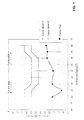
- a prototype device according to the invention was subjected to a test of comparative performance with devices certified according to standard NF P50-413.
- Said certified devices are grouped into class A and class B.
- Class A represents a device with the lowest heights of depression, thus exhibiting poor smoke extraction.
- Class B represents a device with very good heights of depression, therefore exhibiting very good smoke extraction.
- Figure 7 shows the performance graph resulting from this test comparative.
- the curves obtained reflect the heights of depression for each of the categories. Generally speaking, the higher the depression factor is negative, the better the extraction.
- the first curve is obtained with reference to class A devices
- the second curve is obtained with reference to class B devices
- the third curve is obtained with a prototype device according to the present invention.
- the performance graph thus obtained shows that the device according to the invention is clearly more efficient than all the devices certified according to standard NF P50-413.
Landscapes
- Engineering & Computer Science (AREA)
- Chemical & Material Sciences (AREA)
- Combustion & Propulsion (AREA)
- Mechanical Engineering (AREA)
- General Engineering & Computer Science (AREA)
- Jet Pumps And Other Pumps (AREA)
- Working Measures On Existing Buildindgs (AREA)
Applications Claiming Priority (2)
| Application Number | Priority Date | Filing Date | Title |
|---|---|---|---|
| FR0211464A FR2844580B1 (fr) | 2002-09-12 | 2002-09-12 | Dispositif aspirateur statique pour extraction de fumees |
| FR0211464 | 2002-09-12 |
Publications (2)
| Publication Number | Publication Date |
|---|---|
| EP1398567A2 true EP1398567A2 (de) | 2004-03-17 |
| EP1398567A3 EP1398567A3 (de) | 2004-04-21 |
Family
ID=31726068
Family Applications (1)
| Application Number | Title | Priority Date | Filing Date |
|---|---|---|---|
| EP03077912A Withdrawn EP1398567A3 (de) | 2002-09-12 | 2003-09-12 | Schornsteinaufsatz zur Rauchgasabsaugung |
Country Status (2)
| Country | Link |
|---|---|
| EP (1) | EP1398567A3 (de) |
| FR (1) | FR2844580B1 (de) |
Cited By (2)
| Publication number | Priority date | Publication date | Assignee | Title |
|---|---|---|---|---|
| EP2369232A1 (de) * | 2010-03-23 | 2011-09-28 | Gilles Heissat | Vorrichtung zum Schutz eines Abgaskanals gegen Wind und/oder Regen, und Abdeckung dafür |
| DE102010061527A1 (de) * | 2010-12-23 | 2012-06-28 | Peter Grelak | Schornsteinabdeckung |
Family Cites Families (8)
| Publication number | Priority date | Publication date | Assignee | Title |
|---|---|---|---|---|
| GB477374A (en) * | 1936-06-29 | 1937-12-29 | John Blain Hunt | Improvements in or relating to air or smoke inducers |
| GB806319A (en) * | 1956-05-15 | 1958-12-23 | Oswald Dorrington Niblett | Improvements in or relating to ventilator and chimney cowls |
| FR1556262A (de) | 1967-11-27 | 1969-02-07 | ||
| FR1553122A (de) * | 1967-12-01 | 1969-01-10 | ||
| US3523500A (en) * | 1968-10-14 | 1970-08-11 | Edward J Artis | Stationary chimney vacuum cap |
| US3826181A (en) * | 1972-06-09 | 1974-07-30 | G Schrade | Attachment for ventilating shafts or the like |
| FR2231279A5 (en) | 1973-05-23 | 1974-12-20 | Rouquet Jean | Chimney cowl formed of crossed metal bands - ends of bands are attached to tube and bands are in contact in crossing zone |
| US4325291A (en) * | 1980-02-19 | 1982-04-20 | Improved Consumers Products, Inc. | Chimney cap and securement |
-
2002
- 2002-09-12 FR FR0211464A patent/FR2844580B1/fr not_active Expired - Fee Related
-
2003
- 2003-09-12 EP EP03077912A patent/EP1398567A3/de not_active Withdrawn
Cited By (3)
| Publication number | Priority date | Publication date | Assignee | Title |
|---|---|---|---|---|
| EP2369232A1 (de) * | 2010-03-23 | 2011-09-28 | Gilles Heissat | Vorrichtung zum Schutz eines Abgaskanals gegen Wind und/oder Regen, und Abdeckung dafür |
| FR2958011A1 (fr) * | 2010-03-23 | 2011-09-30 | Gilles Heissat | Dispositif de protection d'un conduit d'evacuation de fumees contre les effets du vent et/ou de la pluie, et chapeau correspondant |
| DE102010061527A1 (de) * | 2010-12-23 | 2012-06-28 | Peter Grelak | Schornsteinabdeckung |
Also Published As
| Publication number | Publication date |
|---|---|
| EP1398567A3 (de) | 2004-04-21 |
| FR2844580A1 (fr) | 2004-03-19 |
| FR2844580B1 (fr) | 2005-07-08 |
Similar Documents
| Publication | Publication Date | Title |
|---|---|---|
| EP0641972B1 (de) | Statische, dynamische Gasabfuhreinrichtung | |
| EP0972991B1 (de) | Statische/dynamische Vorrichtung zum Absaugen von Gasen | |
| FR2875858A1 (fr) | Ensemble compose d'un module de puisage et d'un accessoire, inserable dans un reservoir de carburant de vehicule automobile | |
| FR2766014A1 (fr) | Accumulateur acide au plomb, et elements de fermeture et de filtration pour un tel accumulateur | |
| EP1398567A2 (de) | Schornsteinaufsatz zur Rauchgasabsaugung | |
| FR2658271A1 (fr) | Dispositif pour l'aspiration et le rejet de gaz ou fumees et installation comportant une pluralite de tels dispositifs. | |
| FR2951809A1 (fr) | Equipement pour le passage d'un conduit d'evacuation de fumee connecte a une chaudiere, au travers d'une lumiere d'un boisseau de cheminee maconne | |
| EP0100692B1 (de) | Verbindungsvorrichtung für Kaminrohre | |
| EP0641973A1 (de) | Gasabfuhreinrichtung | |
| EP0434577A1 (de) | Auspuffanlage mit Abgasreiniger | |
| EP0656513B1 (de) | Selbstregelnder, rückstromsperrender Lufteinlass versehen mit einer akustischen Rolle, Installation versehen mit einem derartigen Lufteinlass | |
| FR2806460A1 (fr) | Soupape d'aeration comportant un capuchon de protection | |
| FR3008482A1 (fr) | Perfectionnement aux installations de chauffage avec conduit d' evacuation de fumee muni d'une arrivee d'air comburant | |
| EP1450101A1 (de) | Endrohr für ein kombiniertes Luft-Abgasrohr | |
| EP1064167B1 (de) | Entlüftungsvorrichtung für den kraftstofftank eines kraftfahrzeuges | |
| FR2859271A1 (fr) | Dispositif aspirateur statique a venturi oriente par un element de type girouette pour extraction de fumees | |
| FR2543265A1 (fr) | Dispositif modulaire de protection de cheminee participant a l'extraction des fumees et utilise comme registre | |
| FR2855842A1 (fr) | Exutoire de fumees a haute performance aeraulique, specifiquement adapte pour des voutes de toitures de constructions ou de batiments | |
| FR2758177A1 (fr) | Aspirateur statique antirefouleur | |
| EP0663991A1 (de) | Vorrichtung und anlage zur abfallverbrennung. | |
| FR3016430B1 (fr) | Extracteur statique pour conduit d’evacuation d’air ou d’aeration | |
| EP1413827A1 (de) | Antirefluxiver, statischer Rauchgasabsauger | |
| EP0421841A1 (de) | Einrichtung zur Luftführung und Anlage, die eine derartige Einrichtung enthält | |
| FR2842585A1 (fr) | Dispositif d'extraction de gaz stato-mecanique | |
| EP0878664A1 (de) | Gasinjektionsvorrichtung zur Zugerzeugung in einer Gastransportanlage |
Legal Events
| Date | Code | Title | Description |
|---|---|---|---|
| PUAI | Public reference made under article 153(3) epc to a published international application that has entered the european phase |
Free format text: ORIGINAL CODE: 0009012 |
|
| PUAL | Search report despatched |
Free format text: ORIGINAL CODE: 0009013 |
|
| AK | Designated contracting states |
Kind code of ref document: A2 Designated state(s): AT BE BG CH CY CZ DE DK EE ES FI FR GB GR HU IE IT LI LU MC NL PT RO SE SI SK TR |
|
| AX | Request for extension of the european patent |
Extension state: AL LT LV MK |
|
| AK | Designated contracting states |
Kind code of ref document: A3 Designated state(s): AT BE BG CH CY CZ DE DK EE ES FI FR GB GR HU IE IT LI LU MC NL PT RO SE SI SK TR |
|
| AX | Request for extension of the european patent |
Extension state: AL LT LV MK |
|
| RIC1 | Information provided on ipc code assigned before grant |
Ipc: 7F 23L 17/12 B Ipc: 7F 23L 17/02 A |
|
| AKX | Designation fees paid | ||
| REG | Reference to a national code |
Ref country code: DE Ref legal event code: 8566 |
|
| STAA | Information on the status of an ep patent application or granted ep patent |
Free format text: STATUS: THE APPLICATION IS DEEMED TO BE WITHDRAWN |
|
| 18D | Application deemed to be withdrawn |
Effective date: 20041022 |