EP1396392A1 - Gassack mit Fangbändern - Google Patents
Gassack mit Fangbändern Download PDFInfo
- Publication number
- EP1396392A1 EP1396392A1 EP03016630A EP03016630A EP1396392A1 EP 1396392 A1 EP1396392 A1 EP 1396392A1 EP 03016630 A EP03016630 A EP 03016630A EP 03016630 A EP03016630 A EP 03016630A EP 1396392 A1 EP1396392 A1 EP 1396392A1
- Authority
- EP
- European Patent Office
- Prior art keywords
- connecting ring
- gas bag
- seam
- tethers
- airbag
- Prior art date
- Legal status (The legal status is an assumption and is not a legal conclusion. Google has not performed a legal analysis and makes no representation as to the accuracy of the status listed.)
- Granted
Links
Images


Classifications
-
- B—PERFORMING OPERATIONS; TRANSPORTING
- B60—VEHICLES IN GENERAL
- B60R—VEHICLES, VEHICLE FITTINGS, OR VEHICLE PARTS, NOT OTHERWISE PROVIDED FOR
- B60R21/00—Arrangements or fittings on vehicles for protecting or preventing injuries to occupants or pedestrians in case of accidents or other traffic risks
- B60R21/02—Occupant safety arrangements or fittings, e.g. crash pads
- B60R21/16—Inflatable occupant restraints or confinements designed to inflate upon impact or impending impact, e.g. air bags
- B60R21/23—Inflatable members
- B60R21/231—Inflatable members characterised by their shape, construction or spatial configuration
- B60R21/233—Inflatable members characterised by their shape, construction or spatial configuration comprising a plurality of individual compartments; comprising two or more bag-like members, one within the other
-
- B—PERFORMING OPERATIONS; TRANSPORTING
- B60—VEHICLES IN GENERAL
- B60R—VEHICLES, VEHICLE FITTINGS, OR VEHICLE PARTS, NOT OTHERWISE PROVIDED FOR
- B60R21/00—Arrangements or fittings on vehicles for protecting or preventing injuries to occupants or pedestrians in case of accidents or other traffic risks
- B60R21/02—Occupant safety arrangements or fittings, e.g. crash pads
- B60R21/16—Inflatable occupant restraints or confinements designed to inflate upon impact or impending impact, e.g. air bags
- B60R21/23—Inflatable members
- B60R21/231—Inflatable members characterised by their shape, construction or spatial configuration
- B60R21/2334—Expansion control features
- B60R21/2338—Tethers
-
- B—PERFORMING OPERATIONS; TRANSPORTING
- B60—VEHICLES IN GENERAL
- B60R—VEHICLES, VEHICLE FITTINGS, OR VEHICLE PARTS, NOT OTHERWISE PROVIDED FOR
- B60R21/00—Arrangements or fittings on vehicles for protecting or preventing injuries to occupants or pedestrians in case of accidents or other traffic risks
- B60R21/02—Occupant safety arrangements or fittings, e.g. crash pads
- B60R21/16—Inflatable occupant restraints or confinements designed to inflate upon impact or impending impact, e.g. air bags
- B60R21/23—Inflatable members
- B60R21/231—Inflatable members characterised by their shape, construction or spatial configuration
- B60R21/2334—Expansion control features
- B60R21/2338—Tethers
- B60R2021/23382—Internal tether means
-
- B—PERFORMING OPERATIONS; TRANSPORTING
- B60—VEHICLES IN GENERAL
- B60R—VEHICLES, VEHICLE FITTINGS, OR VEHICLE PARTS, NOT OTHERWISE PROVIDED FOR
- B60R21/00—Arrangements or fittings on vehicles for protecting or preventing injuries to occupants or pedestrians in case of accidents or other traffic risks
- B60R21/02—Occupant safety arrangements or fittings, e.g. crash pads
- B60R21/16—Inflatable occupant restraints or confinements designed to inflate upon impact or impending impact, e.g. air bags
- B60R21/23—Inflatable members
- B60R21/235—Inflatable members characterised by their material
- B60R2021/23571—Inflatable members characterised by their material characterised by connections between panels
- B60R2021/23576—Sewing
Definitions
- the invention relates to an airbag, comprising a gas bag wall comprising a top part and the top with an opposite portion of the gas bag wall connecting tethers emanating from a connecting ring, wherein between the connecting ring and the upper part at least one reinforcing layer is provided.
- the arrangement of tethers in the gas bag is a proven means to the Determine deployment behavior and the inflated shape of the gas bag.
- reinforcing layers are used, the attachment of the tethers and the reinforcing layers to the Gas bag wall is usually done over seams.
- the invention provides a way to the force application and force distribution to optimize in the gas bag wall.
- the recording of Forces can also take place in a time staggering, whereby those of the or the first sutures recorded vertical tensile stresses in the first phase the deployment of the airbag and that of the second seam (s) received horizontal tensile stresses at a later stage of deployment be recorded.
- a connecting ring By providing a connecting ring, the one Having recess in the center, also the area of the gas bag wall, where the tethers are attached, are held relatively flexible, which for a more even introduction of force into the gas bag wall than with a disc-shaped connecting element. In addition, so can the material requirement for the gas bag and reduce the volume of the folded gas bag.
- the first seam is radially inward of the transition the tethers is arranged to the connecting ring, because so the Connection ring can be particularly well attached to the gas bag wall.
- the second seam is preferably arranged radially outside the connecting ring. It has been shown that such a good force application can be achieved.
- the reinforcing layer is preferred disc-shaped, so has no central cutout.
- Both the connecting ring and the tethers and the reinforcing layer can consist of pieces of fabric.
- the connecting ring and the tethers are integrally connected, by being formed by a one-piece fabric piece.
- the gas bag has a circular cross-section, and the Connecting ring is located in the center of the circle, so that the introduction of force symmetrical as possible (based on a plan view of the gas bag). A uniform force is supported when the tethers symmetrical and star-shaped are arranged on the connecting ring.
- Figure 1 shows an airbag 10, which is bounded by a gas bag wall 12, in Viewing from the interior of the airbag 10 on the upper part 14. Das das Upper part 14 opposite lower part with the injection mouth is not shown. The upper part 14 is the area of the gas bag 10 with which the occupant is in contact comes.
- Upper part 14 and lower part of the gas bag 10 are additionally by tethers 16, which extend through the interior of the airbag 10.
- the tethers 16 are provided with a closed circumferential connecting ring 18, which has a recess 20 in its interior.
- connecting ring 18 and tethers 16 together as a one-piece fabric layer executed, but they can also be made of several Be composed of sections.
- the connecting ring 18 is on the inside of the airbag 10 with the Upper part 14 connected to fix the tethers 16 on the wall 12, wherein between the connecting ring 18 and the gas bag upper part 14, a reinforcing layer 22nd is arranged.
- the reinforcing layer is preferably also a fabric layer and has a disk-like shape, so has no recess. It can also several reinforcing layers may be provided.
- the not connected to the connecting ring 18 ends of the tethers 16 are known, e.g. attached to the lower part of the gas bag.
- First seams 24 in the example shown here three seams, connect the connecting ring 18, the reinforcing layer 22 and the upper part 14 of the Gas bags 10 firmly together.
- a second one Seam 26 Radially outward of the first seams 24 is a second one Seam 26 is provided, which only the reinforcing layer 22 with the upper part 14 of the Connect gas bags.
- the number of seams is not on the one shown here Example given limited.
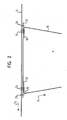
- the second seam 26 is located radially outside the connecting ring 18. It is also radially outward of a point 28 at the a tether 16 merges into the connecting ring 18 and substantially with coincides the point at which the tether 16 from the connecting ring 18 in Interior of the airbag 10 kinks.
- Both the first seams 24 and the second seam 26 are here designed such that that they the connecting ring 18 and the reinforcing layer 22 circumferentially completely circle around. While the first seams 24 in the middle of the connecting ring 18, the second seams 26 are at the edge in this example the reinforcing layer 22 is arranged.
- the first and second seams 24, 26 serve to accommodate various forces.
- the first seams 24 mainly absorb vertically acting forces F 1 , which are transmitted from the tethers 16 to the gas bag wall 12.
- the second seams 26 mainly absorb horizontal forces F 2 , which are caused by the internal pressure p of the gas bag 10.
- the connecting ring is 18 preferably designed annular and, based on the cross section of the gas bag 10, arranged in the middle of the gas bag 10.
- the idea of the invention is also applicable to other types of airbag, wherein the shape of the connecting ring can be adapted to the shape of the gas bag.
- the arrangement of the seams and the tethers on the connecting ring are here shown only as an example.
- the optimal training can be done by a specialist be determined according to the given requirements.
Landscapes
- Engineering & Computer Science (AREA)
- Mechanical Engineering (AREA)
- Air Bags (AREA)
Abstract
Description
- Figur 1 eine schematische Ansicht eines erfindungsgemäßen Gassacks;
- Figur 2 eine schematische Schnittansicht eines erfindungsgemäßen Gassacks;
- Figur 3 eine schematische Ansicht der Krafteinleitung in die Gassackwand bei einem erfindungsgemäßen Gassack; und
- Figur 4 eine schematische Ansicht der Krafteinleitung in die Gassackwand gemäß dem Stand der Technik.
Claims (7)
- Gassack, mit einer ein Oberteil (14) umfassenden Gassackwand (12) und das Oberteil (14) mit einem gegenüberliegenden Abschnitt der Gassackwand (12) verbindenden Fangbändern (16), die von einem Verbindungsring (18) ausgehen,
wobei zwischen dem Verbindungsring (18) und dem Oberteil (14) wenigstens eine Verstärkungslage (22) vorgesehen ist und
wobei wenigstens eine erste Naht (24) vorgesehen ist, die den Verbindungsring (18) und die Verstärkungslage (22) an dem Oberteil (14) befestigt, und
wenigstens eine zweite Naht (26) vorgesehen ist, die nur die Verstärkungslage (22) an dem Oberteil (14) befestigt, wobei die zweite Naht (26) radial außerhalb der ersten Naht (24) angeordnet ist. - Gassack nach Anspruch 1, dadurch gekennzeichnet, daß die erste Naht (24) radial einwärts des Übergangs (28) der Fangbänder (16) zum Verbindungsring (18) angeordnet ist.
- Gassack nach einem der vorhergehenden Ansprüche, dadurch gekennzeichnet, daß die zweite Naht (26) radial außerhalb des Verbindungsrings (18) angeordnet ist.
- Gassack nach einem der vorhergehenden Ansprüche, dadurch gekennzeichnet, daß die Verstärkungslage (22) scheibenförmig ist.
- Gassack nach einem der vorhergehenden Ansprüche, dadurch gekennzeichnet, daß der Verbindungsring (18) und die Fangbänder (16) einstückig verbunden und durch ein gemeinsames Gewebestück gebildet sind.
- Gassack nach einem der vorhergehenden Ansprüche, dadurch gekennzeichnet, daß der Verbindungsring (18), die Fangbänder (16) und die Verstärkungslage (22) aus Gewebestücken bestehen.
- Gassack nach einem der vorhergehenden Ansprüche, dadurch gekennzeichnet, daß der Gassack (10) einen kreisförmigen Querschnitt aufweist und daß sich der Verbindungsring (18) im Zentrum des Kreises befindet.
Applications Claiming Priority (2)
| Application Number | Priority Date | Filing Date | Title |
|---|---|---|---|
| DE20213651U | 2002-09-04 | ||
| DE20213651U DE20213651U1 (de) | 2002-09-04 | 2002-09-04 | Gassack mit Fangbändern |
Publications (2)
| Publication Number | Publication Date |
|---|---|
| EP1396392A1 true EP1396392A1 (de) | 2004-03-10 |
| EP1396392B1 EP1396392B1 (de) | 2006-08-23 |
Family
ID=7974753
Family Applications (1)
| Application Number | Title | Priority Date | Filing Date |
|---|---|---|---|
| EP03016630A Expired - Lifetime EP1396392B1 (de) | 2002-09-04 | 2003-07-30 | Gassack mit Fangbändern |
Country Status (4)
| Country | Link |
|---|---|
| US (1) | US7090249B2 (de) |
| EP (1) | EP1396392B1 (de) |
| DE (2) | DE20213651U1 (de) |
| ES (1) | ES2269877T3 (de) |
Families Citing this family (4)
| Publication number | Priority date | Publication date | Assignee | Title |
|---|---|---|---|---|
| JP4407336B2 (ja) * | 2004-03-24 | 2010-02-03 | 豊田合成株式会社 | エアバッグ装置 |
| US7377548B2 (en) * | 2005-05-06 | 2008-05-27 | Tk Holdings Inc. | Adaptive depth airbag |
| DE102013012017B4 (de) * | 2013-07-19 | 2019-04-18 | Autoliv Development Ab | Airbag |
| DE202019100348U1 (de) * | 2019-01-22 | 2020-04-23 | Dalphi Metal Espana, S.A. | Gassack für ein Fahrzeuginsassen-Rückhaltesystem |
Citations (4)
| Publication number | Priority date | Publication date | Assignee | Title |
|---|---|---|---|---|
| US4934734A (en) * | 1989-03-27 | 1990-06-19 | Juichiro Takada | Inflatable air bag for protection of a vehicle occupant |
| GB2261855A (en) * | 1991-11-30 | 1993-06-02 | Airbags Int Ltd | Limiting strap assembly for a vehicle air bag |
| EP0611683A1 (de) * | 1992-09-14 | 1994-08-24 | Teijin Limited | Luftsack mit verstärkungsgurten |
| JPH06286541A (ja) * | 1993-03-30 | 1994-10-11 | Takata Kk | エアバッグ |
Family Cites Families (9)
| Publication number | Priority date | Publication date | Assignee | Title |
|---|---|---|---|---|
| US5545A (en) * | 1848-05-02 | Improvement in machinery for separating gold | ||
| US2001001A (en) * | 1932-11-23 | 1935-05-14 | Thelen Rolf | Reversible circulation internal fan kiln |
| JP2514725B2 (ja) | 1989-12-08 | 1996-07-10 | タカタ 株式会社 | 車輌用エアバッグ |
| JPH0651460B2 (ja) * | 1990-06-22 | 1994-07-06 | 池田物産株式会社 | 吊りベルト付きエアバッグ装置 |
| US5478114A (en) * | 1994-06-15 | 1995-12-26 | Trw Vehicle Safety Systems Inc. | Air bag tether assembly |
| JP3541471B2 (ja) * | 1995-01-23 | 2004-07-14 | タカタ株式会社 | エアバッグ取付構造 |
| JPH10157546A (ja) * | 1996-11-29 | 1998-06-16 | Takata Kk | 運転席用エアバッグ |
| JPH10166978A (ja) | 1996-12-06 | 1998-06-23 | Toyo Tire & Rubber Co Ltd | 車両用エアバッグ |
| US6733037B1 (en) * | 2000-11-13 | 2004-05-11 | Milliken & Company | Multi-segment air bag tether construction |
-
2002
- 2002-09-04 DE DE20213651U patent/DE20213651U1/de not_active Expired - Lifetime
-
2003
- 2003-07-30 DE DE50304719T patent/DE50304719D1/de not_active Expired - Lifetime
- 2003-07-30 EP EP03016630A patent/EP1396392B1/de not_active Expired - Lifetime
- 2003-07-30 ES ES03016630T patent/ES2269877T3/es not_active Expired - Lifetime
- 2003-08-28 US US10/650,639 patent/US7090249B2/en not_active Expired - Lifetime
Patent Citations (4)
| Publication number | Priority date | Publication date | Assignee | Title |
|---|---|---|---|---|
| US4934734A (en) * | 1989-03-27 | 1990-06-19 | Juichiro Takada | Inflatable air bag for protection of a vehicle occupant |
| GB2261855A (en) * | 1991-11-30 | 1993-06-02 | Airbags Int Ltd | Limiting strap assembly for a vehicle air bag |
| EP0611683A1 (de) * | 1992-09-14 | 1994-08-24 | Teijin Limited | Luftsack mit verstärkungsgurten |
| JPH06286541A (ja) * | 1993-03-30 | 1994-10-11 | Takata Kk | エアバッグ |
Non-Patent Citations (1)
| Title |
|---|
| PATENT ABSTRACTS OF JAPAN vol. 1995, no. 01 28 February 1995 (1995-02-28) * |
Also Published As
| Publication number | Publication date |
|---|---|
| US7090249B2 (en) | 2006-08-15 |
| DE20213651U1 (de) | 2003-01-16 |
| EP1396392B1 (de) | 2006-08-23 |
| ES2269877T3 (es) | 2007-04-01 |
| US20040041384A1 (en) | 2004-03-04 |
| DE50304719D1 (de) | 2006-10-05 |
Similar Documents
| Publication | Publication Date | Title |
|---|---|---|
| EP1511658B1 (de) | Mehrteiliger gassackzuschnitt für einen gassack einer insassenschutzeinrichtung für kraftfahrzeuge und verfahren zur herstellung eines gassackes aus dem gassackzuschnitt | |
| EP1219508B1 (de) | Gassackmodul | |
| EP1231116B1 (de) | Gassack-Modul | |
| EP1231115B1 (de) | Gassack-Modul | |
| DE4315142C2 (de) | Gassack für ein Kraftfahrzeug | |
| DE102009018159A1 (de) | Gassackmodul mit einem eine adaptive Ventilationsöffnung aufweisenden Gassack | |
| DE112004001700T5 (de) | Verbesserungen an oder in Zusammenhang mit einem Gasdeflektor | |
| DE60205797T2 (de) | Gassack-Vorrichtung | |
| DE2522453A1 (de) | Aufblasbares bauwerk | |
| DE69824158T2 (de) | Verbesserung an oder bezüglich einer luftsackanordnung | |
| DE4204758A1 (de) | Filtereinsatz, verfahren zu seiner herstellung und verwendung des filtereinsatzes | |
| EP1467898B1 (de) | Airbagmodul für kraftfahrzeuge | |
| EP1396392B1 (de) | Gassack mit Fangbändern | |
| DE20022019U1 (de) | Gassack-Rückhalteeinrichtung | |
| DE202004006655U1 (de) | Gassack | |
| EP2419305B1 (de) | Gassackanordnung für ein fahrzeuginsassen-rückhaltesystem und verfahren zum herstellen einer gassackanordnung | |
| EP1167128A2 (de) | Luftsack | |
| DE60103849T2 (de) | Rad für ein motorfahrzeug | |
| EP1531095A1 (de) | Gassack | |
| DE102013012017B4 (de) | Airbag | |
| DE102009018168A1 (de) | Gassackmodul für ein Fahrzeuginsassen-Rückhaltesystem und Verfahren zu dessen Herstellung | |
| WO2023241840A1 (de) | Gassack eines fahrzeuginsassen-rückhaltesystems | |
| DE102006031117B4 (de) | Verfahren zum Zusammenbau einer Airbag-Baugruppe und Airbag-Baugruppe | |
| DE10065461C2 (de) | Beifahrerairbagmodul | |
| EP1757493A1 (de) | Gassack für ein Fahrzeuginsassen- Rückhaltesystem |
Legal Events
| Date | Code | Title | Description |
|---|---|---|---|
| PUAI | Public reference made under article 153(3) epc to a published international application that has entered the european phase |
Free format text: ORIGINAL CODE: 0009012 |
|
| AK | Designated contracting states |
Kind code of ref document: A1 Designated state(s): AT BE BG CH CY CZ DE DK EE ES FI FR GB GR HU IE IT LI LU MC NL PT RO SE SI SK TR |
|
| AX | Request for extension of the european patent |
Extension state: AL LT LV MK |
|
| 17P | Request for examination filed |
Effective date: 20040805 |
|
| AKX | Designation fees paid |
Designated state(s): DE ES FR GB IT |
|
| 17Q | First examination report despatched |
Effective date: 20050316 |
|
| GRAP | Despatch of communication of intention to grant a patent |
Free format text: ORIGINAL CODE: EPIDOSNIGR1 |
|
| GRAS | Grant fee paid |
Free format text: ORIGINAL CODE: EPIDOSNIGR3 |
|
| GRAA | (expected) grant |
Free format text: ORIGINAL CODE: 0009210 |
|
| REG | Reference to a national code |
Ref country code: DE Ref legal event code: R081 Ref document number: 50304719 Country of ref document: DE Owner name: ZF AUTOMOTIVE SAFETY GERMANY GMBH, DE Free format text: FORMER OWNER: TRW AUTOMOTIVE SAFETY SYSTEMS GMBH & CO. KG, 63743 ASCHAFFENBURG, DE |
|
| AK | Designated contracting states |
Kind code of ref document: B1 Designated state(s): DE ES FR GB IT |
|
| PG25 | Lapsed in a contracting state [announced via postgrant information from national office to epo] |
Ref country code: IT Free format text: LAPSE BECAUSE OF FAILURE TO SUBMIT A TRANSLATION OF THE DESCRIPTION OR TO PAY THE FEE WITHIN THE PRESCRIBED TIME-LIMIT;WARNING: LAPSES OF ITALIAN PATENTS WITH EFFECTIVE DATE BEFORE 2007 MAY HAVE OCCURRED AT ANY TIME BEFORE 2007. THE CORRECT EFFECTIVE DATE MAY BE DIFFERENT FROM THE ONE RECORDED. Effective date: 20060823 Ref country code: GB Free format text: LAPSE BECAUSE OF FAILURE TO SUBMIT A TRANSLATION OF THE DESCRIPTION OR TO PAY THE FEE WITHIN THE PRESCRIBED TIME-LIMIT Effective date: 20060823 |
|
| REG | Reference to a national code |
Ref country code: GB Ref legal event code: FG4D Free format text: NOT ENGLISH |
|
| REF | Corresponds to: |
Ref document number: 50304719 Country of ref document: DE Date of ref document: 20061005 Kind code of ref document: P |
|
| REG | Reference to a national code |
Ref country code: DE Ref legal event code: R096 Ref document number: 50304719 Country of ref document: DE Effective date: 20061005 |
|
| GBV | Gb: ep patent (uk) treated as always having been void in accordance with gb section 77(7)/1977 [no translation filed] |
Effective date: 20060823 |
|
| ET | Fr: translation filed | ||
| REG | Reference to a national code |
Ref country code: ES Ref legal event code: FG2A Ref document number: 2269877 Country of ref document: ES Kind code of ref document: T3 |
|
| PLBE | No opposition filed within time limit |
Free format text: ORIGINAL CODE: 0009261 |
|
| STAA | Information on the status of an ep patent application or granted ep patent |
Free format text: STATUS: NO OPPOSITION FILED WITHIN TIME LIMIT |
|
| 26N | No opposition filed |
Effective date: 20070524 |
|
| REG | Reference to a national code |
Ref country code: DE Ref legal event code: R097 Ref document number: 50304719 Country of ref document: DE Effective date: 20070524 |
|
| PGFP | Annual fee paid to national office [announced via postgrant information from national office to epo] |
Ref country code: ES Payment date: 20080708 Year of fee payment: 6 |
|
| PGFP | Annual fee paid to national office [announced via postgrant information from national office to epo] |
Ref country code: IT Payment date: 20080724 Year of fee payment: 6 |
|
| REG | Reference to a national code |
Ref country code: ES Ref legal event code: FD2A Effective date: 20090731 |
|
| PG25 | Lapsed in a contracting state [announced via postgrant information from national office to epo] |
Ref country code: ES Free format text: LAPSE BECAUSE OF NON-PAYMENT OF DUE FEES Effective date: 20090731 |
|
| PG25 | Lapsed in a contracting state [announced via postgrant information from national office to epo] |
Ref country code: IT Free format text: LAPSE BECAUSE OF NON-PAYMENT OF DUE FEES Effective date: 20090730 |
|
| REG | Reference to a national code |
Ref country code: FR Ref legal event code: PLFP Year of fee payment: 14 |
|
| REG | Reference to a national code |
Ref country code: FR Ref legal event code: PLFP Year of fee payment: 15 |
|
| REG | Reference to a national code |
Ref country code: FR Ref legal event code: PLFP Year of fee payment: 16 |
|
| PGFP | Annual fee paid to national office [announced via postgrant information from national office to epo] |
Ref country code: FR Payment date: 20190725 Year of fee payment: 17 |
|
| REG | Reference to a national code |
Ref country code: DE Ref legal event code: R081 Ref document number: 50304719 Country of ref document: DE Owner name: ZF AUTOMOTIVE SAFETY GERMANY GMBH, DE Free format text: FORMER OWNER: TRW AUTOMOTIVE SAFETY SYSTEMS GMBH, 63743 ASCHAFFENBURG, DE Ref country code: DE Ref legal event code: R082 Ref document number: 50304719 Country of ref document: DE Representative=s name: PRINZ & PARTNER MBB PATENTANWAELTE RECHTSANWAE, DE |
|
| PG25 | Lapsed in a contracting state [announced via postgrant information from national office to epo] |
Ref country code: FR Free format text: LAPSE BECAUSE OF NON-PAYMENT OF DUE FEES Effective date: 20200731 |
|
| PGFP | Annual fee paid to national office [announced via postgrant information from national office to epo] |
Ref country code: DE Payment date: 20220731 Year of fee payment: 20 |
|
| REG | Reference to a national code |
Ref country code: DE Ref legal event code: R071 Ref document number: 50304719 Country of ref document: DE |
|
| P01 | Opt-out of the competence of the unified patent court (upc) registered |
Effective date: 20230628 |