EP1395753B1 - Pompe haute pression pour un systeme de carburant d'un moteur a combustion interne - Google Patents
Pompe haute pression pour un systeme de carburant d'un moteur a combustion interne Download PDFInfo
- Publication number
- EP1395753B1 EP1395753B1 EP02747167A EP02747167A EP1395753B1 EP 1395753 B1 EP1395753 B1 EP 1395753B1 EP 02747167 A EP02747167 A EP 02747167A EP 02747167 A EP02747167 A EP 02747167A EP 1395753 B1 EP1395753 B1 EP 1395753B1
- Authority
- EP
- European Patent Office
- Prior art keywords
- piston
- bearing
- fluid connection
- shaft
- fuel
- Prior art date
- Legal status (The legal status is an assumption and is not a legal conclusion. Google has not performed a legal analysis and makes no representation as to the accuracy of the status listed.)
- Expired - Lifetime
Links
Images


Classifications
-
- F—MECHANICAL ENGINEERING; LIGHTING; HEATING; WEAPONS; BLASTING
- F02—COMBUSTION ENGINES; HOT-GAS OR COMBUSTION-PRODUCT ENGINE PLANTS
- F02M—SUPPLYING COMBUSTION ENGINES IN GENERAL WITH COMBUSTIBLE MIXTURES OR CONSTITUENTS THEREOF
- F02M63/00—Other fuel-injection apparatus having pertinent characteristics not provided for in groups F02M39/00 - F02M57/00 or F02M67/00; Details, component parts, or accessories of fuel-injection apparatus, not provided for in, or of interest apart from, the apparatus of groups F02M39/00 - F02M61/00 or F02M67/00; Combination of fuel pump with other devices, e.g. lubricating oil pump
- F02M63/02—Fuel-injection apparatus having several injectors fed by a common pumping element, or having several pumping elements feeding a common injector; Fuel-injection apparatus having provisions for cutting-out pumps, pumping elements, or injectors; Fuel-injection apparatus having provisions for variably interconnecting pumping elements and injectors alternatively
- F02M63/0225—Fuel-injection apparatus having a common rail feeding several injectors ; Means for varying pressure in common rails; Pumps feeding common rails
-
- F—MECHANICAL ENGINEERING; LIGHTING; HEATING; WEAPONS; BLASTING
- F02—COMBUSTION ENGINES; HOT-GAS OR COMBUSTION-PRODUCT ENGINE PLANTS
- F02M—SUPPLYING COMBUSTION ENGINES IN GENERAL WITH COMBUSTIBLE MIXTURES OR CONSTITUENTS THEREOF
- F02M59/00—Pumps specially adapted for fuel-injection and not provided for in groups F02M39/00 -F02M57/00, e.g. rotary cylinder-block type of pumps
- F02M59/02—Pumps specially adapted for fuel-injection and not provided for in groups F02M39/00 -F02M57/00, e.g. rotary cylinder-block type of pumps of reciprocating-piston or reciprocating-cylinder type
- F02M59/04—Pumps specially adapted for fuel-injection and not provided for in groups F02M39/00 -F02M57/00, e.g. rotary cylinder-block type of pumps of reciprocating-piston or reciprocating-cylinder type characterised by special arrangement of cylinders with respect to piston-driving shaft, e.g. arranged parallel to that shaft or swash-plate type pumps
- F02M59/06—Pumps specially adapted for fuel-injection and not provided for in groups F02M39/00 -F02M57/00, e.g. rotary cylinder-block type of pumps of reciprocating-piston or reciprocating-cylinder type characterised by special arrangement of cylinders with respect to piston-driving shaft, e.g. arranged parallel to that shaft or swash-plate type pumps with cylinders arranged radially to driving shaft, e.g. in V or star arrangement
-
- F—MECHANICAL ENGINEERING; LIGHTING; HEATING; WEAPONS; BLASTING
- F02—COMBUSTION ENGINES; HOT-GAS OR COMBUSTION-PRODUCT ENGINE PLANTS
- F02M—SUPPLYING COMBUSTION ENGINES IN GENERAL WITH COMBUSTIBLE MIXTURES OR CONSTITUENTS THEREOF
- F02M59/00—Pumps specially adapted for fuel-injection and not provided for in groups F02M39/00 -F02M57/00, e.g. rotary cylinder-block type of pumps
- F02M59/02—Pumps specially adapted for fuel-injection and not provided for in groups F02M39/00 -F02M57/00, e.g. rotary cylinder-block type of pumps of reciprocating-piston or reciprocating-cylinder type
- F02M59/10—Pumps specially adapted for fuel-injection and not provided for in groups F02M39/00 -F02M57/00, e.g. rotary cylinder-block type of pumps of reciprocating-piston or reciprocating-cylinder type characterised by the piston-drive
- F02M59/102—Mechanical drive, e.g. tappets or cams
-
- F—MECHANICAL ENGINEERING; LIGHTING; HEATING; WEAPONS; BLASTING
- F04—POSITIVE - DISPLACEMENT MACHINES FOR LIQUIDS; PUMPS FOR LIQUIDS OR ELASTIC FLUIDS
- F04B—POSITIVE-DISPLACEMENT MACHINES FOR LIQUIDS; PUMPS
- F04B1/00—Multi-cylinder machines or pumps characterised by number or arrangement of cylinders
- F04B1/04—Multi-cylinder machines or pumps characterised by number or arrangement of cylinders having cylinders in star- or fan-arrangement
- F04B1/0404—Details or component parts
- F04B1/0413—Cams
-
- F—MECHANICAL ENGINEERING; LIGHTING; HEATING; WEAPONS; BLASTING
- F04—POSITIVE - DISPLACEMENT MACHINES FOR LIQUIDS; PUMPS FOR LIQUIDS OR ELASTIC FLUIDS
- F04B—POSITIVE-DISPLACEMENT MACHINES FOR LIQUIDS; PUMPS
- F04B49/00—Control, e.g. of pump delivery, or pump pressure of, or safety measures for, machines, pumps, or pumping installations, not otherwise provided for, or of interest apart from, groups F04B1/00 - F04B47/00
- F04B49/22—Control, e.g. of pump delivery, or pump pressure of, or safety measures for, machines, pumps, or pumping installations, not otherwise provided for, or of interest apart from, groups F04B1/00 - F04B47/00 by means of valves
-
- F—MECHANICAL ENGINEERING; LIGHTING; HEATING; WEAPONS; BLASTING
- F04—POSITIVE - DISPLACEMENT MACHINES FOR LIQUIDS; PUMPS FOR LIQUIDS OR ELASTIC FLUIDS
- F04B—POSITIVE-DISPLACEMENT MACHINES FOR LIQUIDS; PUMPS
- F04B53/00—Component parts, details or accessories not provided for in, or of interest apart from, groups F04B1/00 - F04B23/00 or F04B39/00 - F04B47/00
- F04B53/18—Lubricating
-
- F—MECHANICAL ENGINEERING; LIGHTING; HEATING; WEAPONS; BLASTING
- F02—COMBUSTION ENGINES; HOT-GAS OR COMBUSTION-PRODUCT ENGINE PLANTS
- F02M—SUPPLYING COMBUSTION ENGINES IN GENERAL WITH COMBUSTIBLE MIXTURES OR CONSTITUENTS THEREOF
- F02M2200/00—Details of fuel-injection apparatus, not otherwise provided for
- F02M2200/31—Fuel-injection apparatus having hydraulic pressure fluctuations damping elements
- F02M2200/315—Fuel-injection apparatus having hydraulic pressure fluctuations damping elements for damping fuel pressure fluctuations
-
- F—MECHANICAL ENGINEERING; LIGHTING; HEATING; WEAPONS; BLASTING
- F02—COMBUSTION ENGINES; HOT-GAS OR COMBUSTION-PRODUCT ENGINE PLANTS
- F02M—SUPPLYING COMBUSTION ENGINES IN GENERAL WITH COMBUSTIBLE MIXTURES OR CONSTITUENTS THEREOF
- F02M59/00—Pumps specially adapted for fuel-injection and not provided for in groups F02M39/00 -F02M57/00, e.g. rotary cylinder-block type of pumps
- F02M59/02—Pumps specially adapted for fuel-injection and not provided for in groups F02M39/00 -F02M57/00, e.g. rotary cylinder-block type of pumps of reciprocating-piston or reciprocating-cylinder type
Definitions
- the present invention initially relates to a piston pump, in particular a high pressure pump for a fuel system of an internal combustion engine, with a housing, with at least one piston defining a working space, with a drive shaft which is held in the housing via at least one shaft bearing and which has at least one crank portion , And with a piston bearing, via which the piston is supported at least indirectly on the crank portion of the drive shaft, wherein between relatively movable parts of at least one of the bearings, a hydrostatic bearing is present, which is connected via a fluid connection to the working space.
- Such a piston pump is known as a radial piston pump from DE 197 05 205 A1.
- a race is placed on the eccentric portion of a drive shaft. This has a flat contact surface on which a sliding shoe of an axially reciprocating piston rests. Between the contact surface of the race and the shoe a relief chamber is present, which via axial holes in the shoe and in the piston with a from the Piston limited work space is connected.
- the piston performs a delivery stroke, the pressure in the working chamber increases, which is transmitted through the bore in the piston on the discharge chamber and in this way leads to a reduction in the contact force between the shoe and race.
- the discharge chamber so a hydrostatic bearing is created. As a result, the friction and wear between the shoe and race is reduced.
- the present invention therefore has the object, a piston pump of the type mentioned in such a way that it has a better efficiency.
- the period during which fluid flows from the working space into the hydrostatic bearing can be limited to the necessary extent.
- the leakage amount of fluid during operation of the piston pump is reduced, without the friction between relatively movable parts of a bearing of the piston pump would be increased to an undesirable extent.
- the efficiency of the piston pump is increased, without the life of the piston pump is limited.
- any time points can be selected at which the hydrostatic bearing is connected to the working space or to which the connection is interrupted. This allows a reduction in the amount of fluid used for hydrostatic storage.
- the switching valve is the quantity control valve of the piston pump.
- the outlet of the piston pump is usually short-circuited with its inlet toward the end of a delivery stroke, thus limiting the amount of fluid actually delivered.
- hardly any fluid is lost for the hydrostatic bearing, because for that only that fluid is used, which is not to reach the actual outlet of the piston pump anyway to limit the flow rate, but is returned to its inlet.
- the piston pump according to the invention then builds when the device, which can interrupt the fluid connection temporarily, is housed in the piston. But it is also possible to accommodate them in the housing of the piston pump. In this case, the device is more accessible for maintenance purposes, for example.
- the hydrostatic bearing may comprise a chamber which is limited in the azimuthal direction. As a result, the volume of the chamber and thus ultimately the required amount of fluid for the formation of a hydrostatic bearing is reduced.
- the piston pump according to the invention can be designed as a single and multi-cylinder piston pump.
- the angular range over which the chamber extends in the azimuthal direction is preferably less than 360 ° / 2x number of pistons.
- the length and also the width of the chamber creates the optimum hydrostatic bearing for the individual application.
- the fluid connection is connected to a pressure damper.
- This can be used as compression volume, bellows, diaphragm accumulator or similar. be executed.
- a pressure damper By such a pressure damper, the time profile of the fluid flow, which flows from the working space to the chamber, can be designed.
- the device which can temporarily interrupt the fluid connection is the quantity control valve of the piston pump. When this quantity control valve is opened towards the end of the delivery stroke, there is a sudden pressure increase in the fluid connection and thus also in the chamber. By such a pressure damper, this pressure increase can be somewhat flattened.
- the fluid connection to the chamber in the shaft bearing may include a flow channel in the housing, an annular groove in a bearing shell or shaft connected thereto, a radial bore in the shaft connected to the annular groove, an axial bore in the shaft connected thereto and one connected thereto include radial bore in the shaft, which opens into the chamber in the shaft bearing.
- Such holes are easy to incorporate, which facilitates the production of the fluid connection.
- the invention also relates to a fuel system for an internal combustion engine, comprising a fuel tank, a fuel pump which delivers into a fuel rail, and at least one fuel injector connected to the fuel rail and the fuel directly into the combustion chamber of an internal combustion engine injects.
- the invention proposes that the fuel pump is formed in the above manner.
- part of the invention is also an internal combustion engine with at least one combustion chamber, in which the fuel is injected directly.
- an internal combustion engine is advantageously provided with a fuel system of the above type.
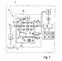
- a fuel system as a whole carries the reference numeral 10. It is part of an internal combustion engine 11 comprises a fuel reservoir 12, from which an electric fuel pump 14 conveys the fuel into a fuel line 16. This leads to an inlet 18 of a generally designated 20 high-pressure fuel pump, which is driven by a crankshaft, not shown, of the internal combustion engine 11.
- a fuel reservoir 12 from which an electric fuel pump 14 conveys the fuel into a fuel line 16.
- a crankshaft not shown
- a fuel line (not numbered) leads to a fuel rail 24, commonly referred to as a "rail".
- a fuel rail 24 To the fuel rail 24 a plurality of fuel injectors 26 are connected. These are high-pressure injectors or injectors. The latter are attached to the engine block (not shown) of an internal combustion engine (not shown) and inject the fuel directly into combustion chambers 28 a.
- the pressure in the fuel rail 24 is detected by a pressure sensor 30, which supplies a corresponding signal to a control and regulating device 32. This, in turn, is on the output side in a manner to be shown in more detail the high-pressure fuel pump 20 is connected.
- the high-pressure fuel pump 20 is a radial piston pump with three radially arranged cylinders. In principle, the high pressure fuel pump 20 is constructed as follows:
- a flow channel 34 leads via a check valve 36 to a branch point 38.
- the check valve 36 opens inwards and thus keeps pressure surges away from the fuel line 16 and the electric fuel pump 14.
- flow channels branch off to the individual cylinders 40a, 40b and 40c.
- the cylinders 40a-40c are constructed identically. For reasons of illustration, the reference numerals are entered only for one cylinder.
- Each cylinder 40a-40c has on the input side via a check valve 42, a pump unit 44 and a check valve 46 arranged downstream of the pump unit 44. Downstream of the check valves 46, the flow channels of the individual cylinders 40a-40c again come together at a collection point 48. From there, a flow channel 50 leads via a further check valve 52 to the outlet 22 of the high-pressure fuel pump 20.
- a flow channel 54 branches off from the flow channel 50, in which a switching valve 56 is arranged.
- This is an electrically operated two / two-way valve, which is open in its rest position 58 and is closed in its actuated position 60.
- the switching valve 56 is controlled by the control and regulating device 32.
- the flow channel 54 leads from the switching valve 56 to a hydrostatic bearing 62, which is explained in detail below.
- a pressure damper 66 Downstream of the switching valve 56 branches off from the flow channel 54 from a flow channel 64, which ultimately between the Check valve 36 and the branch point 38 opens into the flow channel 34.
- a pressure damper 66 In the flow channel 64, a pressure damper 66 is arranged, which in the present case is a spring / piston accumulator. However, the design of the pressure damper 66 as a compression volume, bellows, diaphragm accumulator, etc. is also possible. Upstream of the pressure damper 66 there is a first flow restrictor 68 in the flow channel 64, and downstream of the pressure damper 66 a further flow restrictor 70.
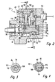
- FIGS. 2-4 The exact configuration of the high-pressure fuel pump 20 can be seen in FIGS. 2-4. It should be noted that in this sectional plane, only one cylinder 40 is shown and individual channels, etc. are not visible.
- the high-pressure fuel pump 20 includes a housing 72.
- a blind hole-like recess 74 is present, the longitudinal axis in Fig. 2 is horizontal.
- a further recess 76 is introduced into the housing 72, which extends vertically in Fig. 2 and from the upper edge of the housing 72 extends into the horizontal recess 74 into it.
- a drive shaft 78 is received in the horizontal recess 74. This is connected to the crankshaft (not shown) of the internal combustion engine.
- the drive shaft 78 is mounted in the region of its two longitudinal ends in each case by a bearing in the housing 72.
- the left-hand bearing in FIG. 2 bears the reference numeral 80.
- the horizontal recess 74 is sealed to the outside by a shaft seal 82.
- the right end of the drive shaft 78 is mounted in a hollow cylindrical bearing shell 84, which forms a shaft bearing.
- the drive shaft 78 Approximately in its axial center, the drive shaft 78 has an eccentric portion 86, on which a race 88 is placed.
- the vertical recess 76 is at the top by a Lid 90 closed.
- a guide sleeve 92 is inserted in the recess 76.
- a piston 94 is guided axially displaceable.
- a foot 96 is welded at the bottom in Fig. 2 end of the piston 94.
- a compression spring 98 is tensioned. By this the foot 96 and thus ultimately the piston 94 is acted upon against the race 88.
- the race 88 thus forms for the piston 94 relative to the drive shaft 78, a piston bearing (without reference numerals).
- a working space 100 is formed. In these opens in Fig. 2 coming from the left that flow channel in which the check valve 42 is arranged. In Fig. 2 to the right of the working space 100 that flow channel runs in which the check valve 46 is arranged. Neither the branching point 38 nor the collecting point 48 are visible in the sectional plane shown in FIG.
- the working space 100 and the piston 94 are part of the pumping unit 44 of the illustrated cylinder 40.
- the hydrostatic bearing 62 is constructed as follows:
- the flow channel 54 leads to the horizontal recess 74. Via a bore 102 in the bearing shell 84, the flow channel 54 is continued up to an annular groove 104 on the inside of the bearing shell 84. At the same axial height as the annular groove 104, a radial bore 106 is introduced into the drive shaft 78, which opens into an axial bore 108 in the drive shaft 78. This continues into the eccentric portion 86 of the drive shaft 78 continues.
- a radial bore 110 leads outwardly to a recess (without reference numeral) on the outer circumferential surface of the drive shaft 78.
- This recess extends, as can be seen in Fig. 3, in azimuthal Direction over an angular range of approximately 60 ° (in Figure 3, for purposes of illustration, only the shaft 78 and the bearing shell 84 are shown; in an embodiment, not shown, the angle is less than 60 °).
- a chamber 112 is formed, in the manner to be explained, a hydrostatic counterforce is generated to the forces resulting from the piston 94.
- the high pressure fuel pump 20 operates as follows:
- the control and regulating device 32 then controls the switching valve 56 so that this opens.
- the fluid communication between the working space 100 and the chambers 112 and 116 of the hydrostatic bearing 62 open.
- This increases the pressure in the chambers 112 and 116, creating a hydrostatic counterforce between the bearing shell 84 and the drive shaft 78 (shaft bearing) and on the other hand between the race 88 and drive shaft 78 (piston bearing) in the desired direction.
- the switching valve 56 is closed again by the control and regulating device 32, whereby the fluid connection between the working chamber 100 and the two chambers 112 and 116 is interrupted again.
- closing the switching valve 56 does not immediately stop the hydrostatic drag generated in the chambers 112 and 116. On the one hand, it takes a certain amount of time until the fluid has flowed away on the one hand through the gap between the drive shaft 78 and the bearing shell 84 and on the other hand between the drive shaft 78 and the race 88.
- the pressure damper 66 acts as a pressure accumulator, which still promotes a certain amount of fluid into the chambers 112 and 116 even when the switching valve 56 is closed.
- the time course of the hydrostatic counterforce generated by the pressure build-up in the chambers 112 and 116 is adjusted on the one hand by the width and the azimuthal angular extent of the chambers 112 and 116 and on the other hand by the properties of the pressure damper 66 and the two flow restrictors 68 and 70.
- the azimuthal angular extent of the chambers 112 and 116 is, as already mentioned, a maximum of 60 °, in each case in a multi-cylinder pump a maximum of 360 ° / 2 x number of cylinders, with three cylinders here so 60 °. This angular extension results from the following considerations:
- the force vector resulting from the pressure load of the pistons of the cylinders 40a to 40c in the present three-cylinder high-pressure pump 20 varies in a range of approximately 60 °, depending The beginning of the area is again offset by about 60 ° in the direction of rotation (arrow 121 in FIGS. 4 and 5) to a co-rotating axis 122 pointing in the eccentric direction. Within the said angular range of the force vector rotates synchronously with the drive shaft 78 about its longitudinal axis.
- the discharge is effected by the hydrostatic force on the piston bearing (race 88 and shaft 78) in the region of the chamber 116 and the shaft bearing (bearing shell 84 and shaft 78) offset by 180 ° in the region of the chamber 112th
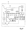
- FIGS. 6 and 7 show a second exemplary embodiment of a high-pressure fuel pump 20.
- Such parts, elements and regions, which have equivalent functions to parts, elements and regions already described above bear the same reference numerals and are not explained again in detail.
- an axially extending groove 120 is still present in the inside of the bearing shell 84. This leads from the space present on the right of the bearing shell 84 to the space left in the recess 74 from the bearing shell 84.
- the groove 120 prevents pressure from building up over the leakage between the drive shaft 78 and the bearing shell 84 at the front end, which is unacceptably high could cause axial forces on the drive shaft 78.
- the left of the bearing shell 84 existing space of the horizontal recess 74 is connected in a manner not shown here with the inlet 18 of the high-pressure fuel pump 20.
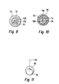
- FIG. 8 shows a further exemplary embodiment of a high-pressure fuel pump. Again, bear such components and areas whose function is equivalent to corresponding components and areas of the preceding figures, the same reference numerals and are not explained again in detail.
- FIG. 8 shows a 1-cylinder piston pump 20 shown.
- the chamber 116 is formed in a range of about 60 ° on both sides of the eccentric axis 122. So it has approximately twice the angular extent as the corresponding chamber in the previous embodiments. Further, it is arranged offset from the previous embodiments by 90 ° counter to the direction of rotation of the drive shaft 78.
- the chamber 112 is offset from the chamber 116 by 180 °, that is arranged with its central axis opposite to the eccentric axis 122.
- the force vector acts in this 1-cylinder fuel pump 20 only in the direction of the cylinder axis, which coincides with the eccentric axis 122 as shown in FIG. 11 at top dead center.
Landscapes
- Engineering & Computer Science (AREA)
- Mechanical Engineering (AREA)
- General Engineering & Computer Science (AREA)
- Chemical & Material Sciences (AREA)
- Combustion & Propulsion (AREA)
- Reciprocating Pumps (AREA)
- Details Of Reciprocating Pumps (AREA)
Claims (12)
- Pompe à piston, notamment pompe haute pression (20) pour un système de carburant (10) d'un moteur à combustion interne, dotée d'un boîtier (72), d'au moins un piston (94) délimitant une chambre de travail (100), d'un arbre d'entraînement (78) maintenu dans le boîtier (72) par au moins un palier d'arbre et présentant au moins un segment de vilebrequin (86), et d'un palier de piston grâce auquel le piston (94) s'appuie au moins indirectement sur le segment de vilebrequin (86) de l'arbre (78), un palier hydrostatique (62) raccordé à la chambre de travail (100) par une communication fluidique étant disponible entre des pièces mobiles les unes par rapport aux autres d'au moins l'un des paliers, avec dans la communication fluidique entre la chambre de travail (100) et le palier hydrostatique (62) un dispositif (56 ; 118) pouvant parfois interrompre la communication fluidique,
caractérisée en ce que
le dispositif pouvant parfois interrompre la communication fluidique comprend une soupape de commutation (56). - Pompe à piston (20) selon la revendication 1,
caractérisée ce que
la soupape de commutation est le régulateur de débit (56) de la pompe à piston. - Pompe à piston (20) selon l'une quelconque des revendications 1 ou 2,
caractérisée ce que
le dispositif pouvant parfois interrompre la communication fluidique est placé dans le piston (94). - Pompe à piston (20) selon l'une quelconque des revendications précédentes,
caractérisée ce que
le dispositif (56 ; 118) pouvant parfois interrompre la communication fluidique est placé dans le boîtier (72). - Pompe à piston (20) selon l'une quelconque des revendications précédentes,
caractérisée ce qu'
au moins un palier hydrostatique (62) est disponible dans le palier de piston et dans le palier d'arbre. - Pompe à piston (20) selon l'une quelconque des revendications précédentes,
caractérisée ce que
le palier hydrostatique (62) comprend au moins une chambre (112, 116) délimitée dans la direction azimutale. - Pompe à piston (20) selon la revendication 8,
caractérisée ce qu'
elle présente plusieurs pistons (94) répartis radialement, la zone angulaire sur laquelle s'étend la chambre (112, 116) dans la direction azimutale est inférieure ou égale à 360° / 2 x le nombre de pistons (94) et cette zone est décalée d'environ 60° dans la direction de rotation par rapport à un axe (122) tournant en direction de l'excentrique. - Pompe à piston (20) selon l'une quelconque des revendications précédentes,
caractérisée ce que
la communication fluidique est reliée à un amortisseur de pression (66). - Pompe à piston (20) selon la revendication 8, selon l'une quelconque des revendications précédentes,
caractérisée ce qu'
au moins un étranglement d'écoulement (68) est prévu entre la communication fluidique et l'amortisseur de pression (66). - Pompe à piston (20) selon l'une quelconque des revendications 6 à 9,
caractérisée ce que
la communication fluidique à la chambre (112) dans le palier d'arbre comprend un canal d'écoulement (54) dans le boîtier (72), une rainure annulaire (104) reliée à ce boîtier dans une coquille de coussinet (84) ou dans l'arbre, un alésage radial (106) relié à la rainure annulaire (104) dans l'arbre (78), un alésage axial (108) relié à celui-ci dans l'arbre (78) et un alésage radial (110) relié à celui-ci dans l'arbre (78) qui débouche dans la chambre (112) dans le palier d'arbre. - Pompe à piston (20) selon la revendication 10,
caractérisée ce que
la communication fluidique à la chambre (116) dans le palier de piston comprend un alésage radial (114) partant de l'alésage axial (108) dans l'arbre (78) et débouchant dans la chambre (116) dans le palier de piston. - Système de carburant (10) pour un moteur à combustion interne (11), doté d'un réservoir de carburant (12), d'une pompe à carburant (20) assurant le transport dans une conduite collectrice de carburant (24) et d'au moins un dispositif d'injection de carburant (26) raccordé à la conduite collectrice de carburant (24) et injectant le carburant directement dans la chambre de combustion (28) du moteur à combustion interne (11),
caractérisé en ce que
la pompe à carburant haute pression (20) est conçue selon l'une quelconque des revendications 1 à 11.
Applications Claiming Priority (5)
| Application Number | Priority Date | Filing Date | Title |
|---|---|---|---|
| DE10125784 | 2001-05-26 | ||
| DE10125784 | 2001-05-26 | ||
| DE10213625A DE10213625A1 (de) | 2001-05-26 | 2002-03-27 | Kolbenpumpe, insbesondere Hochdruckpumpe für ein Kraftstoffsystem einer Brennkraftmaschine, sowie Kraftstoffsystem und Brennkraftmaschine |
| DE10213625 | 2002-03-27 | ||
| PCT/DE2002/001888 WO2002097268A1 (fr) | 2001-05-26 | 2002-05-24 | Pompe haute pression pour un systeme de carburant d'un moteur a combustion interne |
Publications (2)
| Publication Number | Publication Date |
|---|---|
| EP1395753A1 EP1395753A1 (fr) | 2004-03-10 |
| EP1395753B1 true EP1395753B1 (fr) | 2006-08-23 |
Family
ID=26009411
Family Applications (1)
| Application Number | Title | Priority Date | Filing Date |
|---|---|---|---|
| EP02747167A Expired - Lifetime EP1395753B1 (fr) | 2001-05-26 | 2002-05-24 | Pompe haute pression pour un systeme de carburant d'un moteur a combustion interne |
Country Status (4)
| Country | Link |
|---|---|
| US (1) | US6889665B2 (fr) |
| EP (1) | EP1395753B1 (fr) |
| DE (1) | DE50207940D1 (fr) |
| WO (1) | WO2002097268A1 (fr) |
Families Citing this family (11)
| Publication number | Priority date | Publication date | Assignee | Title |
|---|---|---|---|---|
| AU2003281906A1 (en) * | 2003-02-11 | 2004-09-06 | Ganser-Hydromag Ag | High pressure pump |
| KR100992818B1 (ko) | 2004-12-17 | 2010-11-08 | 현대자동차주식회사 | 엔진의 크랭크 오프셋 장치 |
| US20060159572A1 (en) * | 2005-01-18 | 2006-07-20 | Malcolm Higgins | Pilot injection pump |
| DE102005027851A1 (de) * | 2005-06-16 | 2006-12-21 | Robert Bosch Gmbh | Kraftstoffeinspritzsystem für eine Brennkraftmaschine |
| JP4415929B2 (ja) | 2005-11-16 | 2010-02-17 | 株式会社日立製作所 | 高圧燃料供給ポンプ |
| FR2903456B1 (fr) * | 2006-07-07 | 2008-10-17 | Siemens Automotive Hydraulics | Pompe transfert a plusieurs pistons |
| SE530565C2 (sv) * | 2006-11-10 | 2008-07-08 | Scania Cv Ab | Bränslepumpanordning |
| DE102011089399A1 (de) * | 2011-12-21 | 2013-06-27 | Robert Bosch Gmbh | Pumpe, insbesondere Kraftstoffhochdruckpumpe für eine Kraftstoffeinspritzeinrichtung |
| US20130312706A1 (en) * | 2012-05-23 | 2013-11-28 | Christopher J. Salvador | Fuel system having flow-disruption reducer |
| JP6162078B2 (ja) * | 2014-06-17 | 2017-07-12 | 愛三工業株式会社 | 燃料供給装置 |
| JP6369194B2 (ja) * | 2014-07-23 | 2018-08-08 | 株式会社ジェイテクト | 電動ポンプユニット |
Family Cites Families (16)
| Publication number | Priority date | Publication date | Assignee | Title |
|---|---|---|---|---|
| DE1653388B2 (de) | 1967-10-21 | 1975-04-24 | Robert Bosch Gmbh, 7000 Stuttgart | Hydraulische Arbeitsmaschine |
| NL7015670A (fr) * | 1970-10-07 | 1972-04-11 | ||
| DE2141282A1 (de) * | 1971-08-18 | 1973-03-01 | Bosch Gmbh Robert | Hydrostatisches getriebe mit innerer leistungsverzweigung |
| US3828657A (en) * | 1972-06-29 | 1974-08-13 | Fmc Corp | Piston for swash plate pump |
| US3975993A (en) * | 1974-04-22 | 1976-08-24 | Commercial Shearing, Inc. | Piston-rod unit for hydraulic machines |
| US4581980A (en) * | 1984-05-23 | 1986-04-15 | Brueninghaus Hydraulik Gmbh | Hydrostatic axial piston machine with swivelling inclined disc |
| US5634777A (en) * | 1990-06-29 | 1997-06-03 | Albertin; Marc S. | Radial piston fluid machine and/or adjustable rotor |
| DK137393D0 (da) | 1993-12-08 | 1993-12-08 | Danfoss As | Hydraulisk stempelmaskine |
| US5931644A (en) * | 1995-03-30 | 1999-08-03 | Caterpillar Inc. | Precision demand axial piston pump with spring bias means for reducing cavitation |
| DE19705205A1 (de) * | 1997-02-12 | 1998-08-13 | Bosch Gmbh Robert | Kolbenpumpe |
| JP3849825B2 (ja) * | 1997-10-20 | 2006-11-22 | カヤバ工業株式会社 | アキシャルピストンポンプ |
| DE19920168A1 (de) | 1998-05-16 | 1999-11-18 | Luk Automobiltech Gmbh & Co Kg | Radialkolbenpumpe |
| JP2000186649A (ja) * | 1998-12-24 | 2000-07-04 | Isuzu Motors Ltd | 吐出量可変制御型高圧燃料ポンプ |
| DE19900564C2 (de) | 1999-01-09 | 2003-09-18 | Bosch Gmbh Robert | Common-Rail-System |
| US6866025B1 (en) | 1999-11-18 | 2005-03-15 | Siemens Vdo Automotive Corp. | High pressure fuel pump delivery control by piston deactivation |
| US6460510B1 (en) * | 2000-05-30 | 2002-10-08 | Robert H. Breeden | Pump assembly and method |
-
2002
- 2002-05-24 WO PCT/DE2002/001888 patent/WO2002097268A1/fr active IP Right Grant
- 2002-05-24 US US10/333,715 patent/US6889665B2/en not_active Expired - Fee Related
- 2002-05-24 DE DE50207940T patent/DE50207940D1/de not_active Expired - Lifetime
- 2002-05-24 EP EP02747167A patent/EP1395753B1/fr not_active Expired - Lifetime
Also Published As
| Publication number | Publication date |
|---|---|
| US20040047746A1 (en) | 2004-03-11 |
| EP1395753A1 (fr) | 2004-03-10 |
| WO2002097268A1 (fr) | 2002-12-05 |
| DE50207940D1 (de) | 2006-10-05 |
| US6889665B2 (en) | 2005-05-10 |
Similar Documents
| Publication | Publication Date | Title |
|---|---|---|
| DE102004013307B4 (de) | Kraftstoffhochdruckpumpe mit einem Druckbegrenzungsventil | |
| DE102009006909B4 (de) | Axialkolbenmaschine mit reduzierter Stelldruckpulsation | |
| EP1201913B1 (fr) | Pompe de combustible haute pression à débit variable | |
| DE69724695T2 (de) | Radialkolbenpumpe | |
| DE10139054C1 (de) | Verfahren, Computerprogramm, Steuer- und/oder Regelgerät sowie Kraftstoffsystem für eine Brennkraftmaschine, insbesondere mit Direkteinspritzung | |
| EP2670971A2 (fr) | Unité pompe pour une pompe haute pression | |
| EP1395753B1 (fr) | Pompe haute pression pour un systeme de carburant d'un moteur a combustion interne | |
| DE10118884A1 (de) | Hochdruck-Kraftstoffpumpe für ein Kraftstoffsystem einer direkteinspritzenden Brennkraftmaschine, Kraftstoffsystem sowie Brennkraftmaschine | |
| EP1403509B1 (fr) | Dispositif de limitation de pression et système de combustible avec tel dispositif de limitation de pression | |
| DE10350018A1 (de) | Anschlussplatte für eine Axialkolbenpumpe | |
| EP1118771B1 (fr) | Dispositif de régulation de puissance | |
| EP1561028B1 (fr) | Pompe haute pression d'alimentation en carburant comprenant un clapet a bille dans l'admission basse pression | |
| DE112018005595T5 (de) | Kraftstoffzuführpumpe | |
| WO2002081920A1 (fr) | Pompe d'injection a un piston pour systeme d'injection de carburant par accumulation de pression | |
| DE10139055A1 (de) | Verfahren, Computerprogramm, Steuer- und/oder Regelgerät sowie Kraftstoffsystem für eine Brennkraftmaschine | |
| DE10213625A1 (de) | Kolbenpumpe, insbesondere Hochdruckpumpe für ein Kraftstoffsystem einer Brennkraftmaschine, sowie Kraftstoffsystem und Brennkraftmaschine | |
| DE102012215671A1 (de) | Kraftstoffzufuhrpumpe | |
| WO1992008051A1 (fr) | Pompe a pistons, notamment pompe a pistons radiaux | |
| EP1394403B1 (fr) | Système de combustible pour un moteur à combustion interne | |
| AT521269B1 (de) | Hydraulisches Steuerventil für eine längenverstellbare Pleuelstange mit zwei Steuerdruckräumen | |
| EP0757173A2 (fr) | Système d'injection de combustible | |
| DE10138362A1 (de) | Einstempel-Einspritzpumpe für ein Common-Rail-Kraftstoffeinspritzsystem | |
| WO2018077542A1 (fr) | Pompe d'alimentation, en particulier pour carburants cryogéniques | |
| DE10229395A1 (de) | Verdrängermaschine, insbesondere Radialkolbenpumpe in einem Kraftstoffsystem einer Brennkraftmaschine, sowie hydraulisches System | |
| DE10210300B4 (de) | Pumpenelement für eine Hochdruckpumpe und Hochdruckpumpe mit steuerbarer Fördermenge |
Legal Events
| Date | Code | Title | Description |
|---|---|---|---|
| PUAI | Public reference made under article 153(3) epc to a published international application that has entered the european phase |
Free format text: ORIGINAL CODE: 0009012 |
|
| 17P | Request for examination filed |
Effective date: 20031229 |
|
| AK | Designated contracting states |
Kind code of ref document: A1 Designated state(s): AT BE CH CY DE DK ES FI FR GB GR IE IT LI LU MC NL PT SE TR |
|
| 17Q | First examination report despatched |
Effective date: 20050511 |
|
| GRAP | Despatch of communication of intention to grant a patent |
Free format text: ORIGINAL CODE: EPIDOSNIGR1 |
|
| GRAS | Grant fee paid |
Free format text: ORIGINAL CODE: EPIDOSNIGR3 |
|
| GRAA | (expected) grant |
Free format text: ORIGINAL CODE: 0009210 |
|
| AK | Designated contracting states |
Kind code of ref document: B1 Designated state(s): DE FR GB IT TR |
|
| PG25 | Lapsed in a contracting state [announced via postgrant information from national office to epo] |
Ref country code: IT Free format text: LAPSE BECAUSE OF FAILURE TO SUBMIT A TRANSLATION OF THE DESCRIPTION OR TO PAY THE FEE WITHIN THE PRESCRIBED TIME-LIMIT;WARNING: LAPSES OF ITALIAN PATENTS WITH EFFECTIVE DATE BEFORE 2007 MAY HAVE OCCURRED AT ANY TIME BEFORE 2007. THE CORRECT EFFECTIVE DATE MAY BE DIFFERENT FROM THE ONE RECORDED. Effective date: 20060823 Ref country code: GB Free format text: LAPSE BECAUSE OF FAILURE TO SUBMIT A TRANSLATION OF THE DESCRIPTION OR TO PAY THE FEE WITHIN THE PRESCRIBED TIME-LIMIT Effective date: 20060823 |
|
| REG | Reference to a national code |
Ref country code: GB Ref legal event code: FG4D Free format text: NOT ENGLISH |
|
| REF | Corresponds to: |
Ref document number: 50207940 Country of ref document: DE Date of ref document: 20061005 Kind code of ref document: P |
|
| GBV | Gb: ep patent (uk) treated as always having been void in accordance with gb section 77(7)/1977 [no translation filed] |
Effective date: 20060823 |
|
| EN | Fr: translation not filed | ||
| PLBE | No opposition filed within time limit |
Free format text: ORIGINAL CODE: 0009261 |
|
| STAA | Information on the status of an ep patent application or granted ep patent |
Free format text: STATUS: NO OPPOSITION FILED WITHIN TIME LIMIT |
|
| 26N | No opposition filed |
Effective date: 20070524 |
|
| PG25 | Lapsed in a contracting state [announced via postgrant information from national office to epo] |
Ref country code: FR Free format text: LAPSE BECAUSE OF FAILURE TO SUBMIT A TRANSLATION OF THE DESCRIPTION OR TO PAY THE FEE WITHIN THE PRESCRIBED TIME-LIMIT Effective date: 20070511 |
|
| PG25 | Lapsed in a contracting state [announced via postgrant information from national office to epo] |
Ref country code: FR Free format text: LAPSE BECAUSE OF FAILURE TO SUBMIT A TRANSLATION OF THE DESCRIPTION OR TO PAY THE FEE WITHIN THE PRESCRIBED TIME-LIMIT Effective date: 20060823 |
|
| PG25 | Lapsed in a contracting state [announced via postgrant information from national office to epo] |
Ref country code: TR Free format text: LAPSE BECAUSE OF FAILURE TO SUBMIT A TRANSLATION OF THE DESCRIPTION OR TO PAY THE FEE WITHIN THE PRESCRIBED TIME-LIMIT Effective date: 20060823 |
|
| PGFP | Annual fee paid to national office [announced via postgrant information from national office to epo] |
Ref country code: DE Payment date: 20110726 Year of fee payment: 10 |
|
| REG | Reference to a national code |
Ref country code: DE Ref legal event code: R119 Ref document number: 50207940 Country of ref document: DE Effective date: 20121201 |
|
| PG25 | Lapsed in a contracting state [announced via postgrant information from national office to epo] |
Ref country code: DE Free format text: LAPSE BECAUSE OF NON-PAYMENT OF DUE FEES Effective date: 20121201 |