EP1393943A1 - Schiebehimmel für ein Kfz-Schiebe- oder Kfz-Schiebehebedach - Google Patents
Schiebehimmel für ein Kfz-Schiebe- oder Kfz-Schiebehebedach Download PDFInfo
- Publication number
- EP1393943A1 EP1393943A1 EP03017639A EP03017639A EP1393943A1 EP 1393943 A1 EP1393943 A1 EP 1393943A1 EP 03017639 A EP03017639 A EP 03017639A EP 03017639 A EP03017639 A EP 03017639A EP 1393943 A1 EP1393943 A1 EP 1393943A1
- Authority
- EP
- European Patent Office
- Prior art keywords
- receiving groove
- sliding
- edge
- opening edge
- opening
- Prior art date
- Legal status (The legal status is an assumption and is not a legal conclusion. Google has not performed a legal analysis and makes no representation as to the accuracy of the status listed.)
- Granted
Links
Images


Classifications
-
- B—PERFORMING OPERATIONS; TRANSPORTING
- B60—VEHICLES IN GENERAL
- B60J—WINDOWS, WINDSCREENS, NON-FIXED ROOFS, DOORS, OR SIMILAR DEVICES FOR VEHICLES; REMOVABLE EXTERNAL PROTECTIVE COVERINGS SPECIALLY ADAPTED FOR VEHICLES
- B60J7/00—Non-fixed roofs; Roofs with movable panels, e.g. rotary sunroofs
- B60J7/0007—Non-fixed roofs; Roofs with movable panels, e.g. rotary sunroofs moveable head-liners, screens, curtains or blinds for ceilings
- B60J7/003—Non-fixed roofs; Roofs with movable panels, e.g. rotary sunroofs moveable head-liners, screens, curtains or blinds for ceilings one or more sliding rigid plate or lammellae
Definitions
- the invention relates to a sliding roof for a motor vehicle sliding or - Sliding / lifting roof, with a plate-shaped headliner with at least an opening and a ventilation strip protruding through the opening, the at its rear edge a receiving groove for receiving the opening edge of the heavenly body.
- sliding headliner is for example from DE 35 27 839 C1 or known from DE 198 10 505 C1.
- Sliding headliners are known in all Sunroof designs including the so-called sunroofs used and serve the inside of the lid when the roof is closed cover. But they also have the task of at least partially open lid to reduce the incidence of light and the ventilation of the Regulate vehicle interior. Because the sliding headlining is in the visible Area of the vehicle interior, it is on the inside with respect to its Surface quality, at least in its coloring, the rest Vehicle headlining usually adjusted. For example, it consists of a plastic film on the inside or a textile that has foam on the back can.
- a ventilation bar which usually represents a one-piece plastic injection molded part, in one or several openings in the heavenly body.
- the vent bar has in addition, usually a recessed grip with which the sliding headliner from Occupants can be detected and moved along a roof-side guide.
- Breather bar and headliner must have a low bending stiffness be excluded that the opening edge then from the receiving groove is pushed out if the occupant presses too hard on the ventilation strip or pulls, which could even lead to a vent and Heavenly bodies are separated from each other.
- the heavenly body more rigid in the area of the opening edge train by, for example, a perforated sheet embedded in the heavenly body becomes. However, this increases manufacturing costs, weight and costs of the sliding sky.
- the invention creates a sliding headliner that is simple, inexpensive Way a relative movement between the heavenly body and the vent bar in the Area of the receiving groove largely or completely prevented.
- This will be at achieved a sliding headliner of the type mentioned in that in addition to the receiving groove at least one locking connection at the rear edge of the Breather bar is provided, the outward movement of the opening edge counteracts from the receiving groove.
- an additional fuse is provided in the area of the receiving groove, namely in Form of a snap connection.
- the locking connection is not through the receiving groove formed, but represents a separate section of the vent bar.
- the opening edge surrounds the vent bar on its entire circumference.
- one or more latching hooks are in one piece on the vent bar, integrally formed in particular on the upper web of the receiving groove. The latching hook or latches then engage in a corresponding counter structure in the foamed section of the heavenly body.
- the latching hook or latches move according to the preferred one Embodiment when snapping into a plane that is substantially parallel to Is plane that is defined by the receiving groove, i.e. parallel to the plane in which the opening edge is inserted into the receiving groove.
- vent bar increases due to the construction according to the invention the bending stiffness of the sliding headliner by better combining the two parts be connected so that none in the area of the vent bar Reinforcement insert is more necessary in the heavenly body.
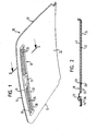
- Figure 1 is the sliding headlining of a motor vehicle sliding or sliding / lifting roof 10 shown below a cover for closing a roof cutout is guided longitudinally. This is done in that the side edges 12 can be received in guide rails, not shown.
- the sliding headliner 10 consists essentially of two parts, namely a large, plate-shaped heavenly body 14 and one near the front Edge 16 of the heavenly body 14, vent bar 18 connected to it, which is preferably made from one part.
- the heavenly body 14 has one or a plurality of openings 20 running along the edge 16 which are formed by one Opening edge 22 of the heavenly body are limited.
- the vent bar 18 is connected and protruding in the region of the opening edge 22 with the headliner 14 through the opening 20.
- the vent bar 18 has one in the middle molded-in recessed grip 24 on which the occupant engages and the sliding headliner can move.
- slot-shaped ventilation openings 26 in the vent bar 18 formed.
- the vent bar 18 has 30 on its rear edge preferably over the entire length of the rear edge 30, one in cross section U-shaped receiving groove 32, which is particularly good in FIGS. 3 to 6 is recognizable.
- the receiving groove 32 is by an upper and a lower Web 34 and 36 defined, which are integrally formed on the vent bar 18 are.
- the lower web 36 runs around the entire outer edge of the Breather bar 18 around and abuts the bottom of the opening edge 22.
- the heavenly body 14 consists of a film or a textile 40 and one PU layer 42.
- the opening edge 22 runs the opening edge 22, its inner portion protrudes into the receiving groove 32.
- the embodiments have in common that one piece on the upper web 34th Snap hooks are formed, which only when the opening edge 22 penetrates into the Snap the receiving groove 32 into a corresponding geometry in the heavenly body 14.
- the snap connections serve to move the opening edge out 22 counteract from the receiving groove 32, especially if the occupant after gripping the recess 24, the ventilation bar 18 upwards presses or pulls down.
- Figures 3A and 3B show two locking hooks 50, the hook-shaped, free Ends facing each other and which extend beyond the upper web 34 in an insertion level (M) defined by the receiving groove 32 for Extend opening edge 22.
- M insertion level
- R-shaped recesses 52 are provided, which in Insert direction R have an undercut in which the free end of the Hooks 50 snaps.
- Large-area tab 54 is formed on the upper web 34, which on the top of the opening edge 22 presses.
- the effect Hook 50 that the opening edge 22 is not in the direction X from the receiving groove 32nd can be moved out.
- the hooks 50 even prevent any movement of heavenly body 14 and vent bar 18 in the direction X.
- the effect of Snap hook 50 is also so advantageous because it snaps into one Move plane E, which is parallel to that formed by the receiving groove 32 Insert plane M and runs perpendicular to the application of force by the occupant.
- the plane E is the horizontal section plane, i.e. the drawing plane according to the figure 3B.
- FIGS. 4A and 4B there is a U-shaped section provided in the upper web 34, which forms a latching hook 50 'with an approximately complementarily formed section 60 at the opening edge 22 locked.
- FIGS. 5A and 5B essentially corresponds that shown in Figures 4A and 4B, wherein the O-shaped locking hook 50 "a has complementary recess 52 "in the thickened part of the opening edge 22.
- the recess 52 surrounds a hook-shaped, upward-facing Extension 62 on the edge 22, which slides into the interior of the locking hook 50 "when the Opening edge 22 has been inserted into the receiving groove 32.
- FIGS. 6A and 6B corresponds in FIG essential of the embodiment shown in Figures 3A and 3B, with the Difference that the recesses 52 "'in the thinner, inner portion of the Opening edge 22 lie and preferably as through openings are trained.
- the hooks 50 "' are formed in the upper web 34 and stand not laterally in front of this, as can be seen in FIG. 3A. This also applies to the tab 54 "'. However, the locking hook 50"' have a greater thickness than that upper web 34 and the flap 54 "', as in the horizontal section according to FIG. 6B see is.
- the vent bar 18 is installed in the opening 20 in that with reference to FIG. 2, the ventilation strip 18 from the front into the opening 20 is inserted until the opening edge 22 has penetrated into the receiving groove 32 is and the locking connections are closed. Then the Vent bar 18 pivoted upward in the area of its front edge 70, formed on the vent bar 70 locking lugs 72, which is also a Form locking connection, have reached the top of the heavenly body 14.
- the sliding headlining receives a relative overall high rigidity, so that no reinforcing inserts in the heavenly body 14 its front, transverse edge 16 and embedded at the opening edge 22 Need to become.
Landscapes
- Engineering & Computer Science (AREA)
- Mechanical Engineering (AREA)
- Vehicle Interior And Exterior Ornaments, Soundproofing, And Insulation (AREA)
- Air-Conditioning For Vehicles (AREA)
- Air-Flow Control Members (AREA)
Abstract
Description
- Figur 1 eine perspektivische Unteransicht des erfindungsgemäßen Schiebehimmels,
- Figur 2 eine Längsschnittansicht durch den Schiebehimmel nach Figur 1,
- Figuren 3A bis 6A perspektivische Ansichten vier verschiedener Ausführungsformen der Rastverbindung im Bereich des hinteren Randes der Entlüftungsleiste und
- Figuren 3B bis 6B Schnittansichten durch die Abschnitte der Entlüftungsleiste und des Himmelkörpers, die in den Figuren 3a bis 6a dargestellt sind.
- 10
- Schiebehimmel
- 12
- Seitenränder
- 14
- Himmelkörper
- 16
- Rand
- 18
- Entlüftungsleiste
- 20
- Öffnungen
- 22
- Öffnungsrand
- 24
- Griffmulde
- 26
- Entlüftungsöffnungen
- 3 0
- Rand
- 32
- Aufnahmenut
- 34
- oberer Steg
- 36
- unterer Steg
- 40
- Textil
- 42
- PU-Schicht
- 50-50'"
- Rasthaken
- 52-52"'
- Ausnehmungen
- 54-54"'
- Lappen
- 60
- Abschnitt
- 62
- Fortsatz
- 70
- Rand
- 72
- Rastnase
Claims (6)
- Schiebehimmel für ein Kfz-Schiebe- oder -Schiebehebedach, mit einem plattenförmigen Himmelkörer (14) mit wenigstens einer Öffnung (20) und einer durch die Öffnung hindurchragenden Entlüftungsleiste (18), die an ihrem hinteren Rand (30) eine Aufnahmenut (32) zur Aufnahme des Öffnungsrandes (22) des Himmelkörpers (14) hat,
dadurch gekennzeichnet, daß
zusätzlich zur Aufnahmenut (32) noch wenigstens eine Rastverbindung am hinteren Rand (30) der Entlüftungsleiste (18) vorgesehen ist, die einem Herausbewegen des Öffnungsrandes (22) aus der Aufnahmenut (32) entgegenwirkt. - Schiebehimmel nach Anspruch 1, dadurch gekennzeichnet, daß wenigstens ein Rasthaken (50; 50'; 50"; 50"') einstückig an der Entlüftungsleiste (18) angeformt ist.
- Schiebehimmel nach Anspruch 1 oder 2, dadurch gekennzeichnet, daß wenigstens ein Rasthaken (50; 50'; 50"; 50"') an einem oberen Steg (34) der Aufnahmenut (32) einstückig angeformt ist.
- Schiebehimmel nach einem der vorhergehenden Ansprüche, dadurch gekennzeichnet, daß sich Rasthaken (50; 50"') beim Einrasten in den Himmelkörper (14) in einer Ebene (E) bewegen, die im wesentlichen parallel zu einer durch die Aufnahmenut (32) definierten Einsteckebene (M) verläuft.
- Schiebehimmel nach einem der vorhergehenden Ansprüche, dadurch gekennzeichnet, daß Rasthaken (50; 50'; 50"; 50"') und der Öffnungsrand (22) so ausgebildet sind, daß die Verrastung erst nach Eindringen des Öffnungsrandes (22) in die Aufnahmenut (32) erfolgt.
- Schiebehimmel nach einem der vorhergehenden Ansprüche, dadurch gekennzeichnet, daß der Himmelkörper (14) an seinem vorderen, quer verlaufenden Rand (16) und am Öffnungsrand (22) keine Verstärkungseinlage hat.
Applications Claiming Priority (2)
| Application Number | Priority Date | Filing Date | Title |
|---|---|---|---|
| DE10240390 | 2002-09-02 | ||
| DE2002140390 DE10240390A1 (de) | 2002-09-02 | 2002-09-02 | Schiebehimmel für ein Kfz-Schiebe- oder -Schiebehebedach |
Publications (2)
| Publication Number | Publication Date |
|---|---|
| EP1393943A1 true EP1393943A1 (de) | 2004-03-03 |
| EP1393943B1 EP1393943B1 (de) | 2006-08-09 |
Family
ID=31197568
Family Applications (1)
| Application Number | Title | Priority Date | Filing Date |
|---|---|---|---|
| EP20030017639 Expired - Lifetime EP1393943B1 (de) | 2002-09-02 | 2003-08-12 | Schiebehimmel für ein Kfz-Schiebe- oder Kfz-Schiebehebedach |
Country Status (4)
| Country | Link |
|---|---|
| EP (1) | EP1393943B1 (de) |
| DE (2) | DE10240390A1 (de) |
| ES (1) | ES2269883T3 (de) |
| MX (1) | MXPA03007819A (de) |
Cited By (3)
| Publication number | Priority date | Publication date | Assignee | Title |
|---|---|---|---|---|
| EP1506887A1 (de) * | 2003-08-14 | 2005-02-16 | Webasto AG | Schiebehimmel für ein Schiebedach eines Kraftfahrzeugs |
| CN102650310A (zh) * | 2011-02-25 | 2012-08-29 | 韦巴斯托股份公司 | 保持装置,制造保持装置的方法及用于机动车的把手标准部件 |
| CN102939220A (zh) * | 2010-01-18 | 2013-02-20 | 佛吉亚汽车外饰有限责任公司 | 纵梁挡板在机动车的纵梁上的固定结构 |
Families Citing this family (1)
| Publication number | Priority date | Publication date | Assignee | Title |
|---|---|---|---|---|
| DE202014006302U1 (de) | 2014-09-05 | 2014-09-16 | Magna Exteriors Gmbh | Befestigung einer Kunststoffverkleidung an einer Tragstruktur eines Kraftfahrzeuges |
Citations (3)
| Publication number | Priority date | Publication date | Assignee | Title |
|---|---|---|---|---|
| DE3527839C1 (de) * | 1985-08-02 | 1986-10-30 | Rockwell Golde Gmbh, 6000 Frankfurt | Schiebehimmel fuer ein Schiebedach fuer Kraftfahrzeuge |
| DE4326547C1 (de) * | 1993-08-07 | 1994-09-15 | Webasto Karosseriesysteme | Befestigungsvorrichtung für einen Himmel |
| DE19821358A1 (de) * | 1997-05-22 | 1998-11-26 | Volkswagen Ag | Lüfterleiste für einen einem beweglichen Glasdach an einem Fahrzeug zugeordneten verschiebbaren Sonnenschutz |
-
2002
- 2002-09-02 DE DE2002140390 patent/DE10240390A1/de not_active Withdrawn
-
2003
- 2003-08-12 DE DE50304551T patent/DE50304551D1/de not_active Expired - Lifetime
- 2003-08-12 ES ES03017639T patent/ES2269883T3/es not_active Expired - Lifetime
- 2003-08-12 EP EP20030017639 patent/EP1393943B1/de not_active Expired - Lifetime
- 2003-08-29 MX MXPA03007819 patent/MXPA03007819A/es active IP Right Grant
Patent Citations (3)
| Publication number | Priority date | Publication date | Assignee | Title |
|---|---|---|---|---|
| DE3527839C1 (de) * | 1985-08-02 | 1986-10-30 | Rockwell Golde Gmbh, 6000 Frankfurt | Schiebehimmel fuer ein Schiebedach fuer Kraftfahrzeuge |
| DE4326547C1 (de) * | 1993-08-07 | 1994-09-15 | Webasto Karosseriesysteme | Befestigungsvorrichtung für einen Himmel |
| DE19821358A1 (de) * | 1997-05-22 | 1998-11-26 | Volkswagen Ag | Lüfterleiste für einen einem beweglichen Glasdach an einem Fahrzeug zugeordneten verschiebbaren Sonnenschutz |
Cited By (6)
| Publication number | Priority date | Publication date | Assignee | Title |
|---|---|---|---|---|
| EP1506887A1 (de) * | 2003-08-14 | 2005-02-16 | Webasto AG | Schiebehimmel für ein Schiebedach eines Kraftfahrzeugs |
| CN102939220A (zh) * | 2010-01-18 | 2013-02-20 | 佛吉亚汽车外饰有限责任公司 | 纵梁挡板在机动车的纵梁上的固定结构 |
| CN102939220B (zh) * | 2010-01-18 | 2015-04-08 | 佛吉亚汽车外饰有限责任公司 | 用于将纵梁挡板固定在机动车的纵梁上的固定结构 |
| CN102650310A (zh) * | 2011-02-25 | 2012-08-29 | 韦巴斯托股份公司 | 保持装置,制造保持装置的方法及用于机动车的把手标准部件 |
| DE102011012406A1 (de) * | 2011-02-25 | 2012-08-30 | Webasto Ag | Halterung, Verfahren zur Herstellung einer Halterung und Griffleiste für ein Fahrzeug |
| CN102650310B (zh) * | 2011-02-25 | 2018-07-10 | 韦巴斯托股份公司 | 保持装置,制造保持装置的方法及用于机动车的把手条 |
Also Published As
| Publication number | Publication date |
|---|---|
| DE50304551D1 (de) | 2006-09-21 |
| EP1393943B1 (de) | 2006-08-09 |
| MXPA03007819A (es) | 2004-12-03 |
| ES2269883T3 (es) | 2007-04-01 |
| DE10240390A1 (de) | 2004-03-11 |
Similar Documents
| Publication | Publication Date | Title |
|---|---|---|
| EP2285612B1 (de) | Profilelement zum verbinden einer fahrzeugscheibe mit einem wasserkasten | |
| DE19746724C1 (de) | Kraftfahrzeugtür mit einer lösbar befestigten Türaußenwandung | |
| DE102016007854B4 (de) | Aufnahmevorrichtung mit Rollo | |
| EP1790514B1 (de) | Türmodulträger | |
| EP1088749A2 (de) | Fahrzeugdach | |
| DE102012003258A1 (de) | Rückluftsperre zur Entlüftung des Innenraums eines Kraftfahrzeugs | |
| EP3374218A1 (de) | Fensterheberbaugruppe mit aneinander clipsbaren führungselementen für ein flächenbündiges scheibenkonzept und montageverfahren | |
| DE3001430A1 (de) | Kofferraumabdeckung fuer kraftfahrzeuge | |
| EP2134915B1 (de) | Führungsschienenanordnung und mitnehmer für kraftfahrzeug-fensterheber sowie verfahren zu deren herstellung | |
| EP3661777B1 (de) | Rolloanordnung mit führungsbändern für rollobahn | |
| DE102012022899A1 (de) | Verbindungselement zur Abstützung eines Stoßfängers eines Kraftfahrzeuges gegenüber einem Montageträger, Baueinheit mit einem solchen Verbindungselement sowie Verfahren zur Herstellung eines Verbindungselements | |
| DE102005056662B4 (de) | Einrichtung zum Befestigen eines Dachgepäckträgers | |
| DE10131829A1 (de) | Gleitfähige Sonnenblende für ein Sonnendach eines Kraftfahrzeuges | |
| DE102005020700B3 (de) | Staubehälteranordnung | |
| EP1393943B1 (de) | Schiebehimmel für ein Kfz-Schiebe- oder Kfz-Schiebehebedach | |
| DE102004038901B3 (de) | Rastkörper zur Befestigung eines Zierstabs | |
| DE10163203C5 (de) | Rolloanordnung für ein Kraftfahrzeug-Seitentürfenster | |
| DE102017000276A1 (de) | Kraftfahrzeugtür mit Türrahmen | |
| DE20218549U1 (de) | Schiebehimmel für ein Kfz-Schiebe- oder Schiebehebedach | |
| EP1219483B1 (de) | Schachtleiste für eine Fahrzeugtüre | |
| DE3024619A1 (de) | Hardtop fuer einen gelaendewagen | |
| DE102019102665A1 (de) | Einzelschuss-Extrusion eines Glaslaufkanals | |
| EP3248837B1 (de) | Kofferaufbau eines nutzfahrzeugs mit ladungssicherungsschiene | |
| DE102007002857B4 (de) | Rolloanordnung mit Führungselement | |
| DE102004007887B4 (de) | Dämpfungsleiste und Rahmen, insbesondere für einen Schiebedachhimmel, Verfahren zum Herstellen einer Dämpfungsleiste bzw. eines Rahmens, insbesondere für einen Schiebedachhimmel |
Legal Events
| Date | Code | Title | Description |
|---|---|---|---|
| PUAI | Public reference made under article 153(3) epc to a published international application that has entered the european phase |
Free format text: ORIGINAL CODE: 0009012 |
|
| AK | Designated contracting states |
Kind code of ref document: A1 Designated state(s): AT BE BG CH CY CZ DE DK EE ES FI FR GB GR HU IE IT LI LU MC NL PT RO SE SI SK TR |
|
| AX | Request for extension of the european patent |
Extension state: AL LT LV MK |
|
| 17P | Request for examination filed |
Effective date: 20040419 |
|
| 17Q | First examination report despatched |
Effective date: 20040513 |
|
| AKX | Designation fees paid |
Designated state(s): CZ DE ES |
|
| GRAP | Despatch of communication of intention to grant a patent |
Free format text: ORIGINAL CODE: EPIDOSNIGR1 |
|
| GRAS | Grant fee paid |
Free format text: ORIGINAL CODE: EPIDOSNIGR3 |
|
| GRAA | (expected) grant |
Free format text: ORIGINAL CODE: 0009210 |
|
| AK | Designated contracting states |
Kind code of ref document: B1 Designated state(s): CZ DE ES |
|
| REF | Corresponds to: |
Ref document number: 50304551 Country of ref document: DE Date of ref document: 20060921 Kind code of ref document: P |
|
| REG | Reference to a national code |
Ref country code: ES Ref legal event code: FG2A Ref document number: 2269883 Country of ref document: ES Kind code of ref document: T3 |
|
| PLBE | No opposition filed within time limit |
Free format text: ORIGINAL CODE: 0009261 |
|
| STAA | Information on the status of an ep patent application or granted ep patent |
Free format text: STATUS: NO OPPOSITION FILED WITHIN TIME LIMIT |
|
| 26N | No opposition filed |
Effective date: 20070510 |
|
| PGFP | Annual fee paid to national office [announced via postgrant information from national office to epo] |
Ref country code: ES Payment date: 20070926 Year of fee payment: 5 |
|
| REG | Reference to a national code |
Ref country code: ES Ref legal event code: FD2A Effective date: 20080813 |
|
| PGFP | Annual fee paid to national office [announced via postgrant information from national office to epo] |
Ref country code: CZ Payment date: 20090728 Year of fee payment: 7 Ref country code: DE Payment date: 20090806 Year of fee payment: 7 |
|
| PG25 | Lapsed in a contracting state [announced via postgrant information from national office to epo] |
Ref country code: ES Free format text: LAPSE BECAUSE OF NON-PAYMENT OF DUE FEES Effective date: 20080813 |
|
| PG25 | Lapsed in a contracting state [announced via postgrant information from national office to epo] |
Ref country code: CZ Free format text: LAPSE BECAUSE OF NON-PAYMENT OF DUE FEES Effective date: 20100812 |
|
| REG | Reference to a national code |
Ref country code: DE Ref legal event code: R119 Ref document number: 50304551 Country of ref document: DE Effective date: 20110301 |
|
| PG25 | Lapsed in a contracting state [announced via postgrant information from national office to epo] |
Ref country code: DE Free format text: LAPSE BECAUSE OF NON-PAYMENT OF DUE FEES Effective date: 20110301 |